

Page 1
RDS110
Smart Thermostat
User Guide
A6V10877569_en--_a
2017-09-08
Building Technologies
Page 2

Siemens
A6V10877569_en--_a
Building Technologies
2017-09-08
2 | 54
Table of Contents
1 About this User guide .................................................................................. 5
1.1 Revision history ............................................................................................... 5
1.2 Reference documents ..................................................................................... 5
1.3 Before you start ............................................................................................... 5
2 Summary ..................................................................................................... 7
2.1 Brief description ............................................................................................... 7
2.2 Inbox items ...................................................................................................... 7
2.3 Equipment combinations ................................................................................. 7
3 Mounting and installation ........................................................................... 10
4 Getting started with your thermostat........................................................... 13
4.1 Setup wizard .................................................................................................. 13
4.2 Thermostat display overview ......................................................................... 14
4.3 Home screen icon overview .......................................................................... 16
5 Presence detection .................................................................................... 17
5.1 Presence detection using the built-in PIR sensor ......................................... 17
5.2 Approach detection ....................................................................................... 18
6 Operating your thermostat from the hardware unit ..................................... 20
6.1 Temperature control ...................................................................................... 20
6.2 Operating modes ........................................................................................... 21
6.2.1 Operating modes that allow for manual switchover ....................... 21
6.2.2 Operating modes in a scheduler .................................................... 22
6.3 WLAN connection .......................................................................................... 22
6.4 Screen lock protection ................................................................................... 24
6.4.1 Locking the home screen ............................................................... 24
6.4.2 Creating an administrator password .............................................. 24
6.5 Turning on/off the supply of domestic hot water ........................................... 25
6.6 Basic settings ................................................................................................ 25
6.6.1 Turning on/off the touch sound ...................................................... 26
6.6.2 Changing the display language ..................................................... 26
6.6.3 Naming a room .............................................................................. 26
6.7 Advanced settings ......................................................................................... 26
6.7.1 Changing a time zone .................................................................... 27
6.7.2 Managing application settings ....................................................... 27
6.7.3 Changing system setup ................................................................. 35
6.7.4 Checking the basic information about your thermostat ................. 37
6.8 Software updates .......................................................................................... 37
7 Green leaf indication .................................................................................. 38
8 Air quality display ....................................................................................... 39
9 Operating the thermostat from the mobile app ........................................... 40
9.1 Downloading the app ..................................................................................... 40
9.2 Account creation and pairing ......................................................................... 40
Page 3

3 | 54
Siemens
A6V10877569_en--_a
Building Technologies
2017-09-08
9.3 Managing the information about your thermostat remotely .......................... 41
9.4 Widget overview ............................................................................................ 41
9.4.1 Temperature control widget overview ............................................ 42
9.4.2 Domestic hot water widget overview ............................................. 43
9.5 Temperature control ...................................................................................... 44
9.6 Turning on/off the supply of domestic hot water ........................................... 44
9.7 Switching between Away and At home ......................................................... 44
9.8 Setting schedulers ......................................................................................... 45
9.9 Switching between heating and OFF modes ................................................ 46
10 Disassembly and disposal ......................................................................... 47
11 Appendices ............................................................................................... 48
11.1 Frequently asked questions .......................................................................... 48
11.1.1 What should I do if I forget the screen lock code?......................... 48
11.1.2 What if two users change the same setting at the same time? ..... 48
11.1.3 Will the thermostat work if the connection to the cloud is lost? ..... 48
11.1.4 Why does the scheduled Eco mode change to Comfort? ............. 48
11.1.5 Why does the thermostat switch to the OFF mode after I’ve
assigned another input for X1 or X2? ........................................................... 49
11.1.6 What is the difference between Administrated WLAN and Private
WLAN? 49
11.1.7 What if the WLAN network is down during software updates? ...... 50
11.1.8 Can I change the Green leaf settings? .......................................... 50
11.1.9 Can I change the air quality measurement standard? ................... 50
11.1.10 Where can I check the current time on the thermostat? ................ 50
11.1.11 Can the thermostat display the time correctly if there is no WLAN
connection? ................................................................................................... 50
11.1.12 Can I set the time manually? ......................................................... 50
11.1.13 Why is the time displayed incorrectly even though the thermostat is
added to a WLAN network? .......................................................................... 51
11.1.14 How does the built-in PIR sensor work? ........................................ 51
11.1.15 What does the Pump/valve kick function mean? ........................... 51
11.1.16 I've registered an account but cannot log in. ................................. 51
11.1.17 I've signed up but have not received a confirmation email. ........... 51
11.1.18 Can I create more than one user account in the mobile app? ....... 51
11.1.19 What should I do if I forget my account’s password? .................... 51
11.2 Technical specifications ................................................................................ 51
11.3 Cyber security disclaimer .............................................................................. 52
11.4 Limited warranty ............................................................................................ 52
Index ................................................................................................................. 53
Page 4

Page 5
About this User guide
Revision history
1
5 | 54
Siemens
A6V10877569_en--_a
Building Technologies
2017-09-08
Edition
Date
Changes
Section
Pages
1
August.
2017
First version.
All
Ref.
Document title
Document number
[1]
Mounting instructions
A6V10733796
[2]
Quick guide
A6V10733808
[3]
Data sheet
A6V10807602
Trademarks
Legal owner
App Store®
Apple Inc.
Google Play™
Google Inc.
Wi-Fi®
Wi-Fi Alliance
Trademarks
Copyright
Quality assurance
Conventions for text
marking
1 About this User guide
1.1 Revision history
1.2 Reference documents
You can download the above documents from
http://siemens.com/bt/download by
searching the document numbers listed above.
1.3 Before you start
The table below lists the third-party trademarks used in this document and their
legal owners. The use of trademarks is subject to international and domestic
provisions of the law.
All product names listed in the table are registered (®) or not registered (™)
trademarks of the owner listed in the table. We forgo the labeling (e.g. using the
symbols ® and ™) of trademarks for the purposes of legibility based on the
reference in this section.
This document may be duplicated and distributed only with the express permission
of Siemens.
These documents were prepared with great care.
● The content of all documents is checked at regular intervals.
● All necessary corrections are included in subsequent versions.
● Documents are automatically amended as a consequence of modifications and
corrections to the products described.
Please make sure that you are aware of the latest document revision date.
If you find any lack of clarity while using this document, or if you have any criticisms
or suggestions, please contact your local point of contact (POC) at the nearest
branch office. Addresses for Siemens RCs are available at
www.siemens.com/sbt.
Markups
Special markups are shown in this document as follows:
Page 6
About this User guide
Before you start
1
6 | 54
Siemens
A6V10877569_en--_a
Building Technologies
2017-09-08
⊳
Specifies the requirements that must be met before performing this
procedure.
1.
2.
Procedures must be performed in the specified order.
[ X]
Reference to a page number
>
Relation sign and for identification between steps in a sequence,
e.g.,
Menu bar > Help > Help topics.
WARNING
This is the symbol for hazard. It warns you of Risks of injury. Comply with all
measures designated by this symbol to prevent injury or death.
NOTICE
This symbol identifies an important notice that you should be aware of when you
are using the product.
The 'i' symbol identifies supplementary information and tips for an easier way of
working.
Document use/ request to
the reader
Symbol identifications
Before using products from Siemens Industry, Inc., it is important that you read the
documents supplied with or ordered at the same time as the products (equipment,
applications, tools, and so on) carefully and in full.
Before you get started, make sure you have an internet connection, a valid Email
address and a smartphone in hand.
Additional information on products and applications is available:
● At your Siemens branch office
www.siemens.com/sbt or at your system
suppliers.
● From the support team in the headquarters
fieldsupport-
zug.ch.sbt@siemens.com if no local POC is available.
Siemens assumes no liability to the extent allowed under the law for any losses
resulting from a failure to comply with the aforementioned points or for the
improper compliance of the same.
Page 7
Summary
Brief description
2
7 | 54
Siemens
A6V10877569_en--_a
Building Technologies
2017-09-08
Items
Quantity
Thermostat (front and rear)
1
Metallic mounting plate
1
Set of screws and plastic insert
1
Quick guide
1
Mounting instructions
1
Activation code sticker
1
Wiring sticker
1
Type of unit
Product no.
LGNi1000
at 0 °C
Pt1000
at 0 °C
NTC
10k at
25 °C
DC 0…10
V
Datasheet
*
Room temperature sensors
- Wall-mounted
QAA24
x 1721
QAA2012
x 1745
QAA2030
x 1745
QAA2061
x 1749
QAA2061D2)
x 1749
- Flushmounted1)
AQR2531AN
W
x 1408
AQR2532N
NW
x 1411
- Concealed
QAA64
(vandalproof)
x 1722
Outdoor temperature sensors
QAC22
x 1811
QAC2012
x 1811
2 Summary
2.1 Brief description
Smart Thermostat RDS110 is designed to control your heating system in
apartments, single family homes, dormitories and other residential-type as well as
light commercial spaces. Apart from traditional operations performed directly on the
hardware unit, remote operations that use a mobile app are also allowed for your
convenience.
2.2 Inbox items
2.3 Equipment combinations
Remote sensors
Page 8
Summary
Equipment combinations
2
8 | 54
Siemens
A6V10877569_en--_a
Building Technologies
2017-09-08
Type of unit
Product no.
LGNi1000
at 0 °C
Pt1000
at 0 °C
NTC
10k at
25 °C
DC 0…10
V
Datasheet
*
QAC2030
x 1811
QAC3161
x 1814
Cable temperature sensors
QAP21.3
x 1832
QAP22
x 1831
QAP21.3/80
00
x 1832
QAP2012.15
0
x 1831
QAP1030.20
0
x 1831
Room humidity sensors
- Wall-mounted
QFA2000
x 1857
- Wall-mounted
including
temperature
QFA2020
x (T)
x (r.h.)
1857
QFA2060
x (T+r.h.)
1857
QFA2060D2)
x (T+r.h.)
1857
- Flushmounted1)
including
temperature
AQR2534AN
W
+
AQR2540Nx
x (T)
x (r.h.)
1410
AQR2535N
NW
+
AQR2540Nx
x (T+r.h.)
1410
Type of unit
Product no.
Datasheet*
Electromotoric actuator
SFA21/18
4863
SUA21/3
A6V10446174
* The documents can be downloaded from
http://siemens.com/bt/download by
specifying the product number as shown in the above table.
1) Requires a mounting plate and/or design frames.
2) With digital display.
Actuators
Page 9
Summary
Equipment combinations
2
9 | 54
Siemens
A6V10877569_en--_a
Building Technologies
2017-09-08
Type of unit
Product no.
Datasheet*
Electrothermal actuator (for
radiator valves) AC 230 V,
NO
STA23..
4884
Electrothermal actuator (for
radiator valves) AC 24 V,
NO
STA73..
4884
Electrothermal actuator
AC 230 V (for small valves
2.5 mm), NC
STP23..
4884
Electrothermal actuator
AC 24 V (for small valves
2.5 mm), NC
STP73..
4884
Type of unit
Product no.
Datasheet*
White decoration frame and
metallic mounting plate for
installation on rectangular conduit
box (10 sets)
ARG100.01
S55772-T102
A6V1119064
0
Accessory
* The documents can be downloaded from
specifying the product number as shown in the above table.
http://siemens.com/bt/download by
Page 10
Mounting and installation
3
10 | 54
Siemens
A6V10877569_en--_a
Building Technologies
2017-09-08
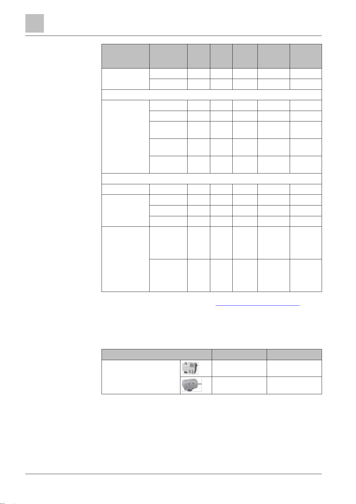
Mounting
Installing your thermostat
3 Mounting and installation
● The thermostat is suitable for wall mounting.
● The recommended height is 1.50 m above the floor.
● Do not mount the thermostat in recesses, shelves, behind curtains or doors, or
above or near heat sources.
● Avoid direct solar radiation and drafts.
● Seal the conduit box or the installation tube if any, as air currents can affect
sensor readings.
● Adhere to allowed ambient conditions.
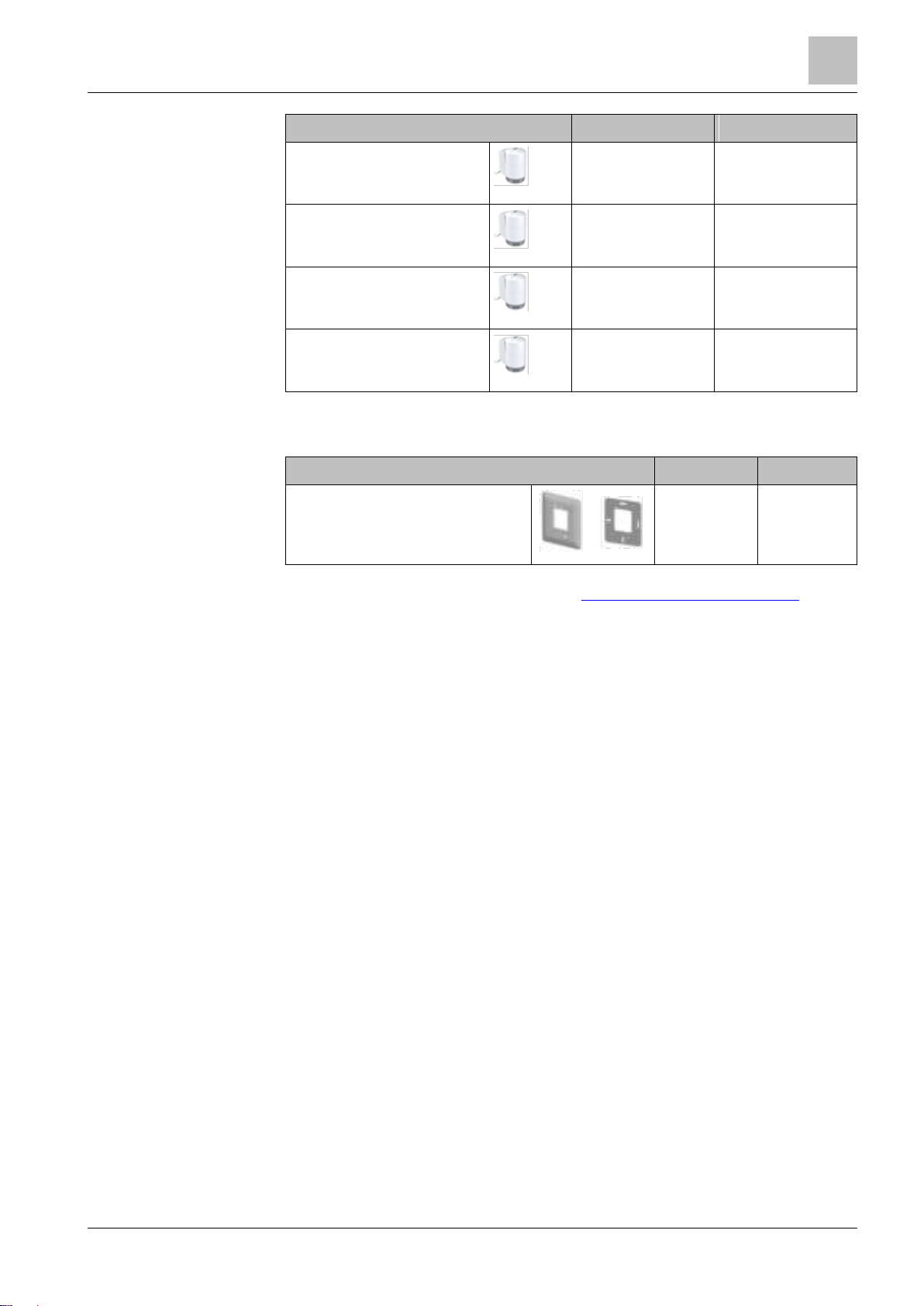
1. Switch off power to your heating system by using either your home’s breaker
box or the system’s power switch.
2. Remove the cover of your old thermostat.
3. Label the wires according to your old thermostat terminal designations, using
the stickers provided together with the thermostat. It is also helpful if you take a
picture of the current wire connections for reference later on.
Page 11
Mounting and installation
3
11 | 54
Siemens
A6V10877569_en--_a
Building Technologies
2017-09-08
4. Disconnect all the labeled wires and then remove your old thermostat.
NOTICE! Do not throw your old thermostat in the trash if it contains mercury in
a sealed tube. You can contact a thermostat recycling organization, for
example, www.thermostat-recycle.org, for safe disposal of your old thermostat.
5. Check whether you need to have more wires connected to the power unit to be
installed. If yes, prepare the wires and label them accordingly. Normally, at
least three wires are needed for the thermostat to work meaningfully. It is
strongly recommended that you turn to installers for wire connection.
6. Seal the conduit box or the installation tube to prevent entrance of cold or warm
air and ensure the correctness of temperature readings by the internal sensor.
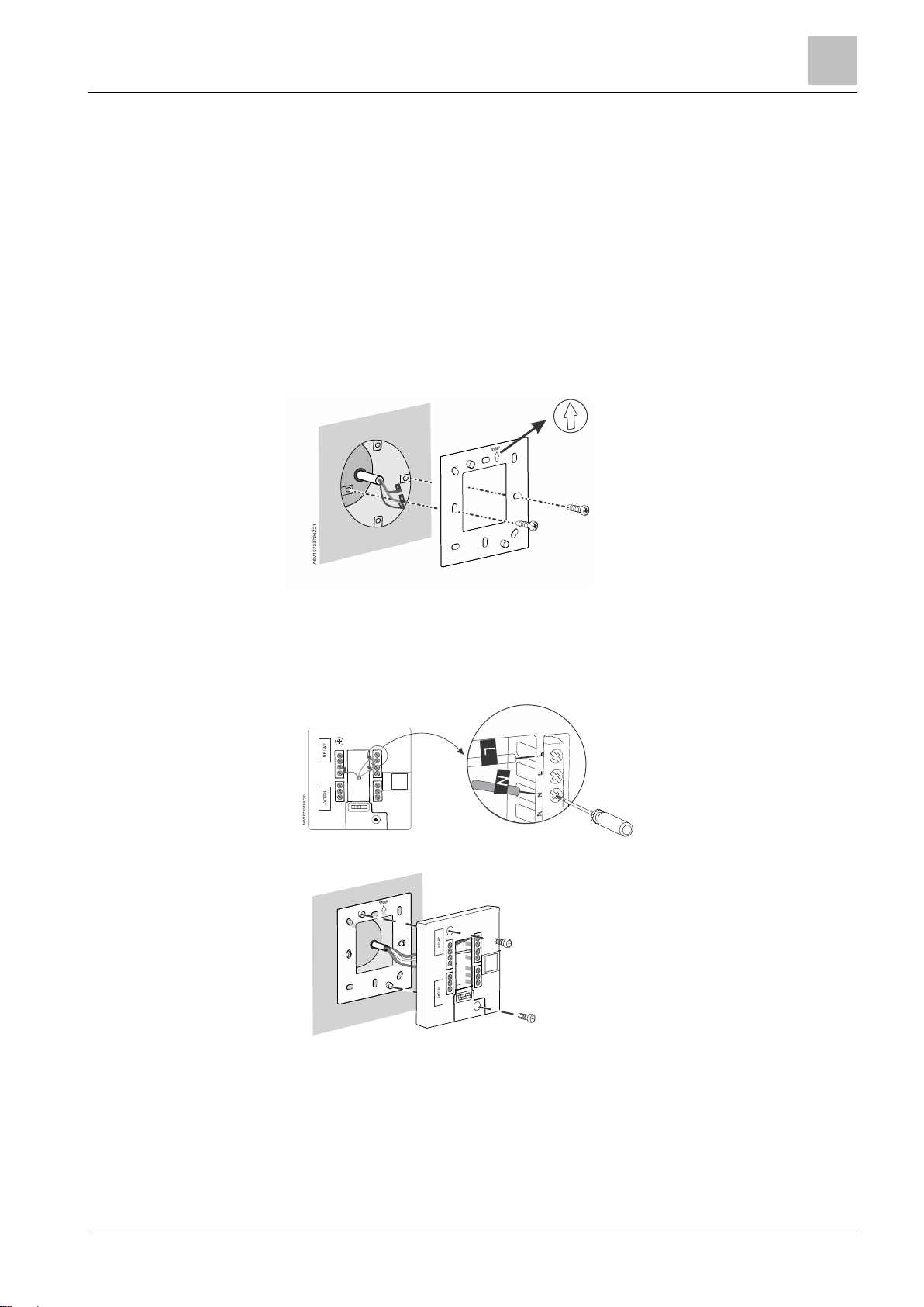
7. Screw the mounting plate tightly on the conduit box using a screwdriver,
making sure that the mounting plate is placed correctly (the part with the
upward arrow is placed on the top).
8. Connect the labeled wires to the terminal tightly according to your thermostat
terminal designations (you may also refer to the picture you take in Step3), and
then fix all the inserted wires by screwing down the screws. Note that the wiring
for your application might be different from the schematic drawing shown
below.
9. Screw the power unit on the mounting plate tightly.
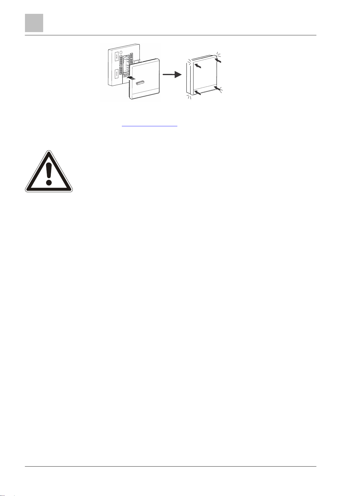
10. Attach the front module horizontally, making sure that each side of the front
module fully aligns with that of the power unit, and then press each corner of
the front module until you hear a click sound.
Page 12
Mounting and installation
3
12 | 54
Siemens
A6V10877569_en--_a
Building Technologies
2017-09-08
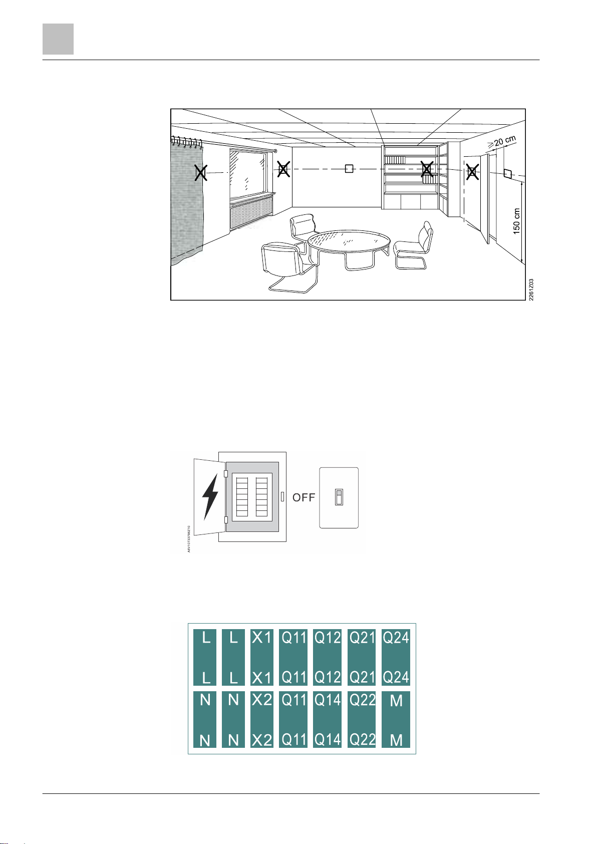
Wiring
11. Switch on power to your heating system. Your thermostat powers on too.
See the Mounting instructions for more information. Note that a bridge between
one Q11 terminal and terminal L is pre-wired. It is not recommended to remove this
pre-wiring bridge unless requested.
● Comply with local regulations to wire, fuse and earth the thermostat. It is
recommended that the conduit box is connected to the earth (safety ground).
● Adapt the line diameters as per local regulations to the rated value of the
installed overcurrent protection device.
● The line voltage cables and signal cables should be arranged separately.
● X1, M and X2 wires operate at SELV (Safety Extra Low Voltage) level. You
must not insert cables of AC 230 V mains voltage into terminals X1, M and X2
and vice versa.
● Isolate the cables of inputs X1, M and X2 from the AC 230 V mains voltage.
● The AC 230 V mains supply line must have an external circuit breaker with a
rated current of no more than 10 A.
● You must not tear off the two insulation tapes on the lower part of the back of
the power unit; otherwise, it might cause risks of electric shock.
● Properly size the cables to the thermostat and valve actuators.
● Do screw the cables tightly and ensure that no bare copper is exposed.
● Use valve actuators rated for AC 230 V. If a valve actuator rated for AC 24 V is
used, use a transformer before connecting it to the thermostat.
● Disconnect from power supply before removing the front module and the
mounting plate.
Page 13
Getting started with your thermostat
Setup wizard
4
13 | 54
Siemens
A6V10877569_en--_a
Building Technologies
2017-09-08
4 Getting started with your thermostat
4.1 Setup wizard
When your thermostat is powered up for the first time, a setup wizard displays to
guide you through the following procedures:
● Setting a display language
● Setting an administrator password
● Setting up a network connection and choosing the network connection type
● Selecting an equipment type and setting up the details
● Configuring time and date
● Specifying a name to the location where the thermostat is installed
For more details, see the Quick guide.
Page 14
Getting started with your thermostat
Thermostat display overview
4
14 | 54
Siemens
A6V10877569_en--_a
Building Technologies
2017-09-08
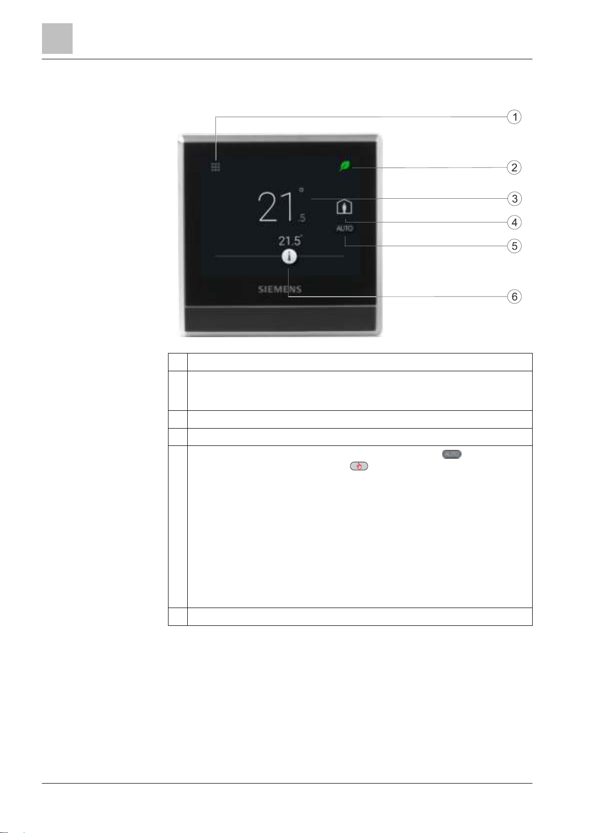
1
Tap to display detailed information and additional settings.
2
Displays whether the system is in an energy-optimized mode. If the leaf is
red, predefined settings were changed. Tap the red leaf to restore the
energy-saving mode. The leaf again turns green.
3
Room temperature.
4
Tap to toggle between At home and Away.
5
Displays whether the thermostat is following a scheduler ( ) or following
your setpoint changes permanently ( ). Following a scheduler can mean
the following:
● If there is network connection and you’ve also set your scheduler, the
thermostat follows your scheduler. Your temporary change of the
temperature setpoint only takes effect during the currently scheduled
mode.
● If there is network connection but you haven’t set a scheduler, the
thermostat follows the default scheduler set by the system. For more
information about the default scheduler, see Setting schedulers [
45].
● If there is no network connection or valid time, the thermostat cannot
retrieve scheduler information from the Cloud. It always works under the
Comfort mode.
6
Tap or slide to change the room temperature setpoint.
Normal display
4.2 Thermostat display overview
Page 15
Getting started with your thermostat
Thermostat display overview
4
15 | 54
Siemens
A6V10877569_en--_a
Building Technologies
2017-09-08
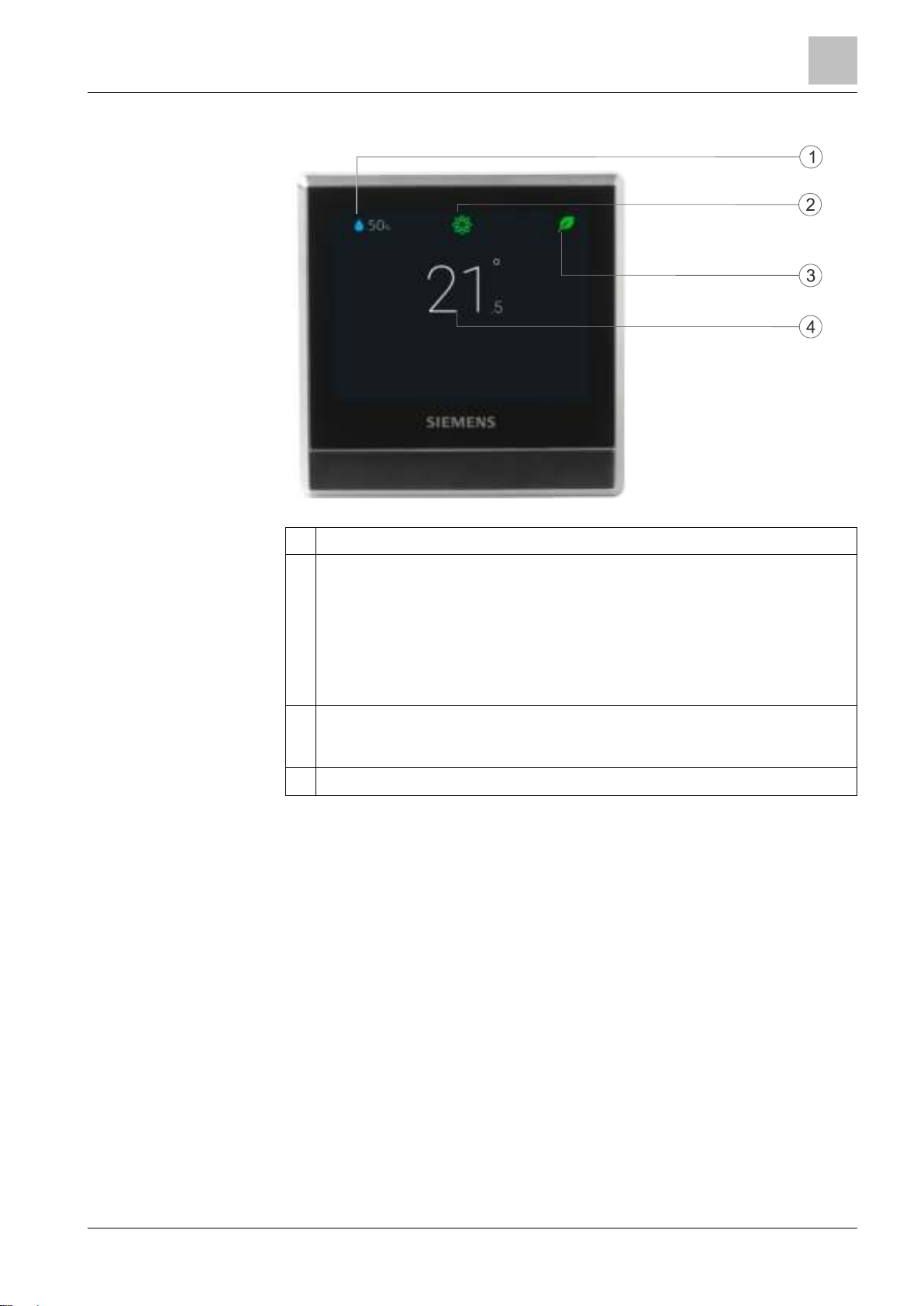
1
Relative room humidity
2
Shows room air quality:
● If the icon is green, the air quality is good.
● If the icon is orange, the air quality is moderate.
● If the icon is red, the air quality is poor.
In order to ensure that the room air quality is measured accurately when the
room is closed for a long time, it is recommended to force air circulation such
as opening a window.
3
Displays whether the system is in an energy-optimized mode. If the leaf is
red, predefined settings were changed. Tap the red leaf to restore the
energy-saving mode. The leaf again turns green.
4
Room temperature.
Idle display
NOTE: The icons displayed under the idle mode may differ under different
scenarios.
Page 16
Getting started with your thermostat
Home screen icon overview
4
16 | 54
Siemens
A6V10877569_en--_a
Building Technologies
2017-09-08
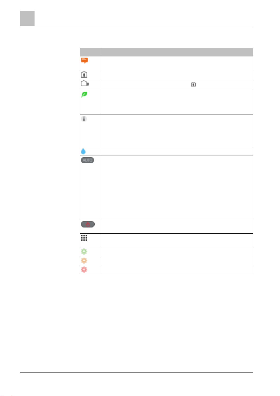
Icon
Description
The device is connected to the cloud but not associated with an
account.
At home mode is on.
AWAY mode is on. You must manually tap to activate this mode.
Displays when the system works in an energy-optimized mode. If the
leaf is red, it means that some pre-defined settings have been changed.
You can tap the red leaf to restore to the energy-saving mode. The leaf
turns green again.
Temperature setpoint slider. The background color of this icon changes
along with major changes to the setpoints:
● If you increase the setpoint by dragging the slider to the right to
warm up the room, the slider color changes to orange.
● If no heating occurs, the slider color changes to white.
Relative room humidity
The thermostat works following a scheduler. If you haven’t set one, the
thermostat works following a default scheduler. This default scheduler
could be set by the system, or specified by yourself if you have changed
the default setpoints of some operating modes under
Advanced settings
>
Optimization.
When this icon is toggled on, temperature setpoint changes can only be
maintained within the current scheduled mode and will be overridden to
the scheduled setpoint when the next scheduled mode starts.
NOTE: If the thermostat has never been connected to a WLAN network,
it cannot read the real time from the network and thus cannot follow a
scheduler. In this case, it always works under the
Comfort mode.
The thermostat doesn’t work following a scheduler. All of your
temporary setpoint changes work continuously if this icon is toggled on.
Tap to display options, such as Operation mode, Settings and
Advanced settings.
Indicates the room air quality is good.
Indicates the room air quality is okay.
Indicates the room air quality is poor.
4.3 Home screen icon overview
Page 17
Presence detection
Presence detection using the built-in PIR sensor
5
17 | 54
Siemens
A6V10877569_en--_a
Building Technologies
2017-09-08
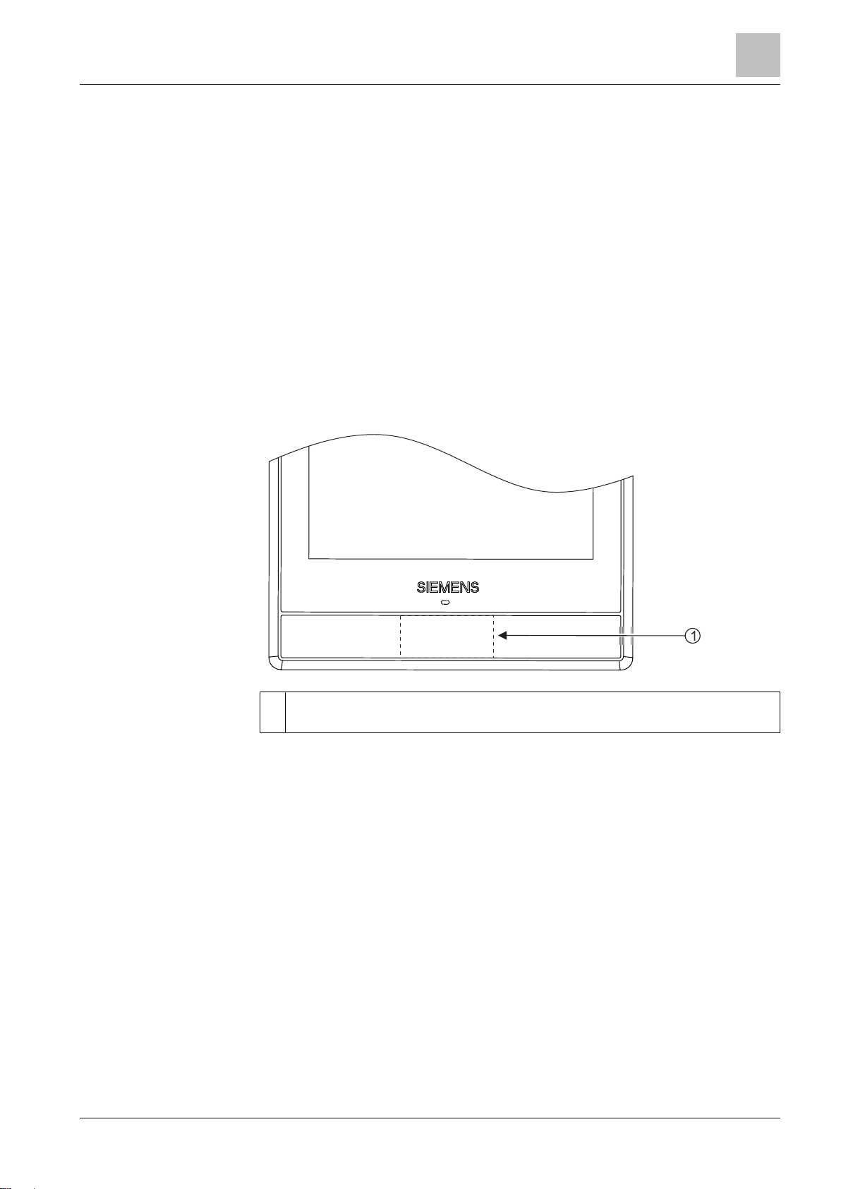
1
The location of the PIR sensor. It is a black area if seen from the front of the
front module.
5 Presence detection
5.1 Presence detection using the built-in PIR sensor
By using a built-in presence detection sensor (also called PIR (Passive infrared
detector) sensor), the thermostat can detect the space occupancy and then do the
following:
● Activate the idle display. When no operations are performed, the thermostat
detects whether someone is in the room or not. If it detects someone is in the
room, it displays information such as room temperature, room air quality and
relative room humidity. If it detects no one is in the room, it turns off the screen.
● Change the operating mode from
is detected to be occupied when a scheduled
thermostat switches to
Comfort automatically until the next scheduled mode
starts. However, you can decide not to switch to
Sensor location
Economy to Comfort. If an unoccupied room
Economy mode is running, the
Comfort if you want.
Page 18

Presence detection
Approach detection
5
18 | 54
Siemens
A6V10877569_en--_a
Building Technologies
2017-09-08
A
The width of each cell. It is 80 cm (31 in).
B
The thermostat.
C
The height of each cell. It is 80 cm (31 in).
D
The area that the PIR sensor can detect.
Sensor detection range
To disable the switch from Economy to Comfort even if the room is
occupied
1. From the Home screen, tap , tap and then tap .
2. If prompted, enter the administrator password.
3. Tap , tap , and then tap . Scroll down and tap Room presence detector.
4. Drag the slider to the left.
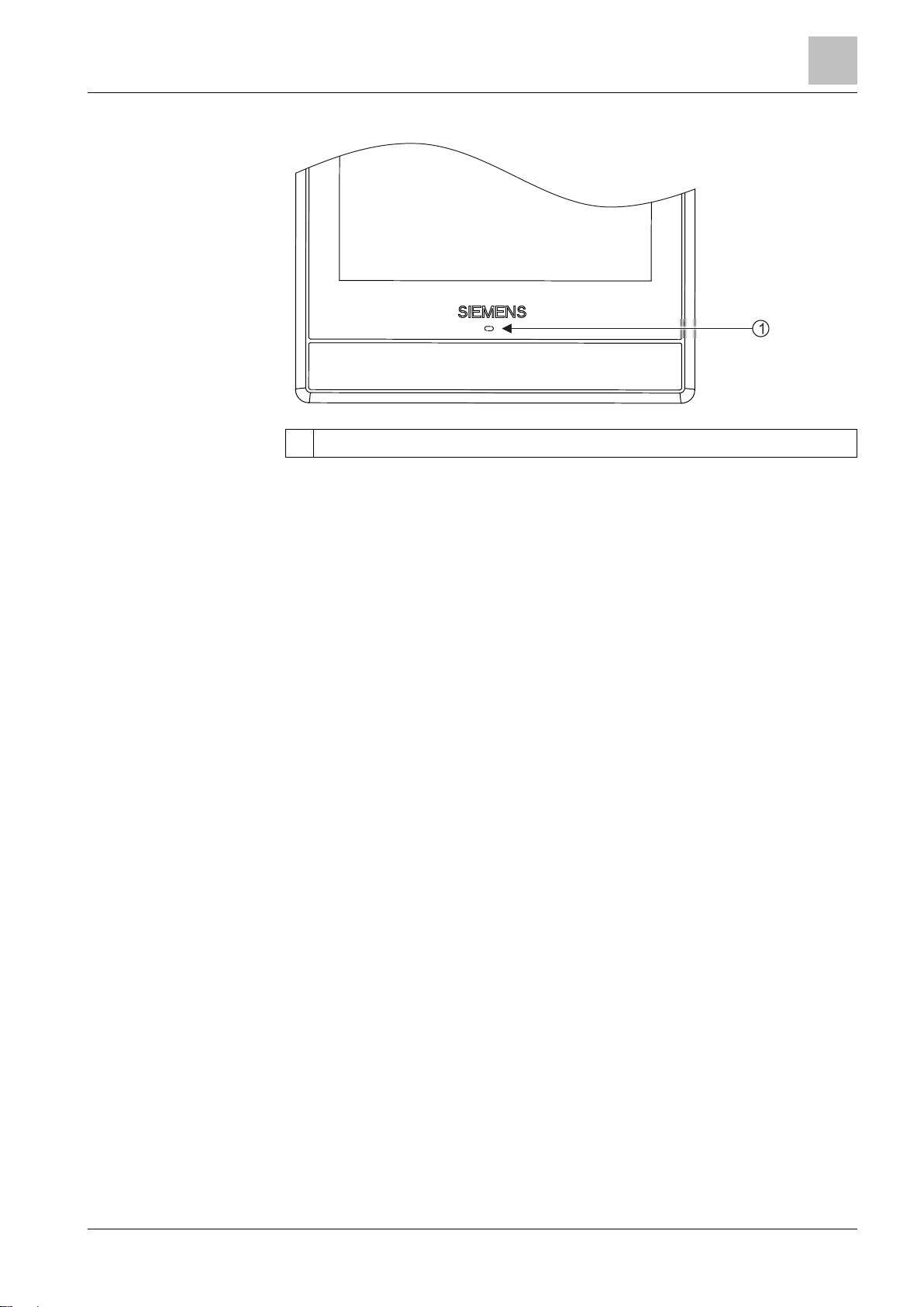
5.2 Approach detection
The thermostat has a built-in approach sensor. It can detect someone approaching
the thermostat. If activity is sensed within 10 cm, it will switch from its idle screen to
the main home screen with full temperature and setpoint display.
Page 19
Presence detection
Approach detection
5
19 | 54
Siemens
A6V10877569_en--_a
Building Technologies
2017-09-08
1
The location of the approach sensor.
Sensor position
Page 20

Operating your thermostat from the hardware unit
Temperature control
6
20 | 54
Siemens
A6V10877569_en--_a
Building Technologies
2017-09-08
NOTICE
After the initial setup of the thermostat, the displayed room temperature may not
be correct because the temperature sensors need time for the calibration. Wait for
at least one hour for the calibration.
6 Operating your thermostat from the hardware
unit
6.1 Temperature control
Your thermostat acquires the room temperature using the built-in sensor and/or the
external room temperature sensor, and maintains the setpoint by delivering control
commands to heating equipment. On the home screen, you can see the current
room temperature and adjust the temperature setpoint as you want.
Your thermostat also allows you to select your preferable temperature unit between
°C (the default unit) and °F.
To adjust the temperature setpoint on the home screen
● From the Home screen, drag the temperature slider to the right to increase the
temperature setpoint, or to the left to decrease the temperature setpoint.
To change the temperature unit
1. From the Home screen, tap , and then tap .
2. Tap , then tap to change from Celsius to Fahrenheit, or tap to change
from Fahrenheit to Celsius.
Page 21

Operating your thermostat from the hardware unit
Operating modes
6
21 | 54
Siemens
A6V10877569_en--_a
Building Technologies
2017-09-08
Operating
mode
Description
At home
You can use this mode when you stay at home or inside the
room where the thermostat is located.
When the thermostat operates under this mode, you can toggle
to to let the thermostat run automatically following a
scheduler, or toggle to to let the thermostat operate at a
specified setpoint permanently. See Thermostat display overview
[
14] for more detailed information about how the thermostat
works when or is toggled on.
AWAY
This mode helps save energy. You can use this mode when you
are away from home or outside the room where the thermostat is
located.
The temperature setpoint maintained under this mode is the
same with that scheduled in
Economy mode using the mobile
app. Deactivation of this mode switches the thermostat to the
scheduler you’ve set (if you haven’t set one, the thermostat works
following a default scheduler).
OFF
Depending on how you’ve set up the thermostat, this mode can
mean one of the following:
● Your heating equipment turns off completely.
● Your thermostat only works to maintain the system’s
protection setpoint so that your heating equipment is not
destroyed if the room air temperature is too low, or if the air is
too humidified or dry. For more information about the
protection setpoint, see Managing application settings [
27].
Deactivation of this mode switches the thermostat to the
scheduler you’ve set (if you haven’t set one, the thermostat
follows a default scheduler).
6.2 Operating modes
6.2.1 Operating modes that allow for manual switchover
Operating mode overview
To switch to the OFF mode
● From the Home screen, tap , and then tap
NOTE: To awake your thermostat from the OFF mode, tap the screen.
To change the thermostat behavior under the OFF mode
1. From the Home screen, tap , then tap and .
2. If prompted, enter the administrator password.
3. Tap > , and then tap Off/protection configuration.
4. Tap either Off or Protection.
To switch between At home and AWAY modes
● From the Home screen, tap to switch from
● Tap to switch from AWAY to At home.
OFF on the Operation mode page.
At home to AWAY.
Page 22

Operating your thermostat from the hardware unit
WLAN connection
6
22 | 54
Siemens
A6V10877569_en--_a
Building Technologies
2017-09-08
Operating mode
Description
Comfort
Makes you feel comfortable when you are at home or inside
the room where the thermostat is located.
Pre-Comfort
Makes you feel comfortable when you are asleep. It also
helps save energy.
Economy
Save energy when you are away from home or outside the
room where the thermostat is located.
6.2.2 Operating modes in a scheduler
Operating mode overview
These operating modes are different in terms of temperature setpoints, humidity
setpoints and de-humidity setpoints. You can adjust these setpoints for different
operating modes under
setpoint or de-humidity setpoint, you can temporarily adjust the temperature
setpoint directly from the thermostat home screen or using the mobile app.
You can only see and schedule these operating modes in a mobile app. However,
on the hardware unit, you can switch the thermostat to operate automatically
following a scheduler. When a scheduler is running, the above modes operate as
scheduled within different periods of a day (If you haven’t set one, the thermostat
works following a default scheduler). If you’ve changed a temperature setpoint
when a scheduler is running, your change only works temporarily within the current
scheduled mode and will be overridden to the scheduled settings when the next
scheduled mode starts. You can see the overriding information on both the
thermostat screen and app screen.
NOTE: See Setting schedulers [ 45] for more details about scheduling.
Advanced settings > Optimization. Unlike the humidity
To switch the thermostat to work following a scheduler
● From the Home screen, tap if is not displayed on the screen.
NOTE: Unlike when a scheduler is running, all your changes work permanently if
is toggled on.
6.3 WLAN connection
Connecting to a WLAN network allows you to connect to the cloud server and
control your thermostat from a smartphone. Depending on how you’ve set the
thermostat to connect to the Internet, you must go to
to manage the WLAN connection:
● If you’ve selected
● if you’ve selected
settings.
To connect to a network
1. If the thermostat is selected for commercial use, do the following:
– From the Home screen, tap , then tap . The
displays.
– If required, enter your administrator password.
– Tap > , and then wait for the thermostat to discover the networks
nearby.
Private WLAN (home use), go to Settings.
Administrated WLAN (commercial use), go to Advanced
Advanced settings or Settings
Advanced settings page
2. If the thermostat is selected for home use, do the following:
Page 23
Operating your thermostat from the hardware unit
WLAN connection
6
23 | 54
Siemens
A6V10877569_en--_a
Building Technologies
2017-09-08
– From the Home screen, tap , and then tap until the Settings page
displays.
– Tap > , and then wait for the thermostat to discover the networks
nearby.
– Tap your desired network. If necessary, tap or to scroll through the
networks to select one.
4. For secured networks, enter the relevant password, and then tap Connect.
Note: For more information about the administrator password, see Creating an
administrator password [
24].
To add a network manually
1. If the thermostat is selected for commercial use:
– On the Advanced settings page, tap > , and then tap to scroll down
to find and tap Add network.
2. If the thermostat is selected for home use:
– On the
Settings page, tap > , and then tap to scroll down to find and
tap Add network.
3. Enter the Network name (SSID) information.
4. To select a security type, tap the Security field.
5. Tap Connect.
6. If prompted, enter the relevant password, and then tap Connect.
To configure your current network settings
1. If the thermostat is selected for commercial use:
– On the Advanced settings page, tap > . Your current network displays
on the screen.
2. If the thermostat is selected for home use:
– On the Settings page, tap > . Your current network displays on the
screen.
3. Tap Network settings. The default DHCP (Dynamic host configuration protocol)
setting page displays on the screen.
– If necessary, tap or to scroll through and view other network DHCP
settings like
– If you want to customize the current network settings, tap Manual, select a
field, or tap or to scroll to the desired field, and then enter a new
setting.
Preferred DNS.
Connecting to a network via the push button
If you have little knowledge about wireless security, using the push button method
makes it easy for you to establish a secure wireless network connection. If you
want to use this method, you must have a WPS (Wi-Fi Protected Setup) compatible
router.
To connect to a network using the push button
1. If the thermostat is selected for commercial use:
– On the Advanced settings page, tap > , then tap until you see Push
button setup.
2. If the thermostat is selected for home use:
Page 24

Operating your thermostat from the hardware unit
Screen lock protection
6
24 | 54
Siemens
A6V10877569_en--_a
Building Technologies
2017-09-08
NOTICE
If your thermostat is selected for home use, it is recommended that you don't
create an administrator password because there is no way to change it to a new
password if you’ve lost or cannot remember it. If you’ve created a password but
lost it, contact the product supplier or the agency for support.
– On the Settings page, tap > , then tap until you see Push button
setup.
3. Tap Push button setup, and then press the WPS button on your WPS-
supported router to start the discovery of your thermostat.
4. On the thermostat, tap > Connect.
5. Tap OK once the thermostat is connected to the network successfully.
6.4 Screen lock protection
6.4.1 Locking the home screen
Whether the thermostat is selected for commercial or home use, you can set a
numeric screen code to lock the home screen and protect the thermostat from
misuse.
Apart from using the screen code to unlock the screen, you can also use an
administrator password (if you've set one) to unlock the screen.
To create a screen lock code
1. From the Home screen, tap , then tap .
2. Tap > > Activate. Enter a code consisting of six numbers, and then tap OK.
3. Tap OK again to confirm.
To unlock the home screen
● On the Home screen, enter the screen lock code directly and then tap
● If you’ve set an administration password, tap the question mark on the screen,
and then tap
NOTE: There is no limit of attempts to enter the numeric code. If you cannot
remember the screen lock code, you can use the administrator password (if you’ve
set one) to unlock the screen. For more information, see What should I do if I forget
the screen lock code? [
Log in as administrator.
48]
OK.
To modify a screen lock password
1. On the Settings page, tap .
2. Tap > Change, specify a new numeric lock of six numbers, and then tap OK.
3. Tap OK to confirm.
To remove a screen lock password
1. On the Settings page, tap .
2. Tap > Deactivate, then tap OK to confirm.
6.4.2 Creating an administrator password
Page 25

Operating your thermostat from the hardware unit
Turning on/off the supply of domestic hot water
6
25 | 54
Siemens
A6V10877569_en--_a
Building Technologies
2017-09-08
If your thermostat is selected for home use, options related to WLAN connection
is accessible from
Settings instead of Advanced settings.
If your thermostat is selected for commercial use, setting an administrator
password can help you prevent unauthorized access to
installed in a public place. You can create the password in the setup wizard when
you use your thermostat for the first time. You can also create, modify or deactivate
it later under
Actions protected by the administrator password are listed as below. You can find
them under
● Checking the basic information about the thermostat.
● Viewing/Using the activation code of the thermostat.
● Changing or deactivating the administrator password.
● Setting up WLAN connection.
● Changing date and time.
● Changing application settings.
● Changing basic/extended configurations and doing factory resets.
If you cannot remember the created administrator password, turn to the product
supplier or agency for support.
Advanced settings.
Advanced settings as well.
Advanced settings if it is
To create/activate an administrator password under Advanced
settings
1. From the Home screen, tap , then tap . The Advanced settings page
displays.
2. Tap > Password > Activate.
3. View the password policy on the screen, and then tap .
4. Enter a strong password required by the password policy, and then tap OK.
5. Tap OK.
To manage your administrator password
1. On the Advanced settings page, tap > Password.
2. Modify or deactivate the administrator password.
6.5 Turning on/off the supply of domestic hot water
Use your thermostat to manage the supply of DHW (Domestic Hot Water) if
corresponding external equipment is connected with your thermostat and you’ve
also configured the thermostat output as a domestic hot water boiler. You can turn
on or off the supply of domestic hot water, or let the thermostat automatically adjust
whether and when to turn it on.
To turn on/off the supply of domestic hot water
1. From the Home screen, tap , then tap > .
2. Tap either ON, OFF or AUTO.
6.6 Basic settings
Under basic settings, you can:
● Lock/Unlock the home screen [
● Change the temperature unit [
24]
20]
Page 26

Operating your thermostat from the hardware unit
Advanced settings
6
26 | 54
Siemens
A6V10877569_en--_a
Building Technologies
2017-09-08
● Connect to a WLAN network [ 22] if the thermostat is selected for home use
● Turn on/off the touch sound
● Change the display language
● Specify a room name
The first three options are described in separate sections. This section only
describes the last three options.
6.6.1 Turning on/off the touch sound
You can adjust whether the thermostat responds to your touching actions with
sounds.
To turn on/off the touch sound
1. From the Home screen, tap , then tap until the Settings page displays.
2. Tap , and then tap or to turn on or off the touch sound.
6.6.2 Changing the display language
To change the display language
1. On the Settings page, tap > .
2. Tap the new language that you want to change to. If necessary, tap to scroll
to the desired language.
6.6.3 Naming a room
You can give a unique name to a room where your thermostat is installed. Doing
so helps you easily recognize the room when you are remotely controlling the
thermostat.
To name a room
1. On the Settings page, tap > .
2. Tap the text field, and then enter a room name as desired, or tap to select a
name from the pre-set list.
3. Tap OK once you’ve entered the room name.
6.7 Advanced settings
NOTE: It is recommended that only installers or experts with detailed know-how
about the thermostat change advanced settings.
Under Advanced settings, you can:
● Manage the administrator password [
● Connect to a WLAN network [
use
● Scan the QR code of the activation code [
● Change a time zone
● Adjust different application settings
● Re-set up the thermostat
● Check the basic information about your thermostat
The first three options are described in separate sections. This section describes
the remaining options.
22] if the thermostat is selected for commercial
24]
40]
Page 27

Operating your thermostat from the hardware unit
Advanced settings
6
27 | 54
Siemens
A6V10877569_en--_a
Building Technologies
2017-09-08
No.
Application
settings
Descriptions
Factory
settings
Range
Dependencies
1.
X1 room
temp. ref.
at 0V
Room temperature at
0 V of the 0-10 V input
in terminal X1
0 °C
-50…80 °C
A DC 0…10 V
external room
temperature
sensor must be
connected with
the thermostat
using terminal
X1.
2.
X1 room
temp. ref.
at 10V
Room temperature at
10 V of the 0-10 V
input in terminal X1
50 °C
-50…80 °C
3.
X2 room
temp. ref.
at 0V
Room temperature at
0 V of the 0-10 V input
in terminal X2
0 °C
-50…80 °C
A DC 0…10 V
external room
temperature
sensor must be
connected with
the thermostat
using terminal
X2.
4.
X2 room
temp. ref.
at 10V
Room temperature at
10 V of the 0-10 V
input in terminal X2
50 °C
-50…80 °C
5.
Outside
temp. ref.
at 0V
Outside air
temperature at 0 V of
the 0-10 V input
-50 °C
-50…80 °C
A DC 0…10 V
external
outside air
temperature
sensor must be
connected.
6.
Outside
temp. ref.
at 10V
Outside air
temperature at 10 V of
the 0-10 V input
80 °C
-50…80 °C
Multi-functional inputs
6.7.1 Changing a time zone
When there is internet connection, the thermostat automatically detects the time
zone for you. However, you can also change it manually.
To change the time zone
1. From the Home screen, tap , then tap and .
2. If prompted, enter the administrator password.
3. Tap > > Adapt, and then select an area on the map.
4. Tap or to scroll to a desired time zone, tap to select it and then tap .
5. If it is connecting to the cloud, the thermostat detects the date and time
automatically for you based on your previously-selected time zone. If it is not
connecting to the cloud, follow the on-screen instructions to set the year, month
and date manually.
6.7.2 Managing application settings
You can manage application settings by turning on/off a specific function or change
setting values. It is strongly recommended that only installers or experts with
detailed know-how about the thermostat modify the application settings.
NOTE:
● Parameter availability depends on your selected application for your
thermostat.
● Numbers marked in the above table are only for easy readability in this
document. They don't represent the parameter numbers in the local hardware
unit.
Page 28

Operating your thermostat from the hardware unit
Advanced settings
6
28 | 54
Siemens
A6V10877569_en--_a
Building Technologies
2017-09-08
No.
Application
settings
Descriptions
Factory
settings
Range
Dependencies
7.
X1 floor
temp. ref.
at 0V
Floor temperature at
0 V of the 0-10 V input
in terminal X1
-50 °C
-50…80 °C
A DC 0…10 V
external floor
temperature
sensor must be
connected
using terminal
X1.
8.
X1 floor
temp. ref.
at 10V
Floor temperature at
10 V of the 0-10 V
input in terminal X1
80 °C
-50…80 °C
9.
X2 floor
temp. ref.
at 0V
Floor temperature at
0 V of the 0-10 V input
in terminal X2
-50 °C
-50…80 °C
A DC 0…10 V
external floor
temperature
sensor must be
connected
using terminal
X2.
10.
X2 floor
temp. ref.
at 10V
Floor temperature at
10 V of the 0-10 V
input in terminal X2
80 °C
-50…80 °C
No.
Application
settings
Descriptions
Factory
settings
Range
Dependencies
11.
Heating
setpoint for
comfort
The default heating
setpoint for
Comfort
defined in a scheduler.
This setpoint must be
higher than that for
protection.
21 °C
0…50 °C
N/A
12.
Heating
setpoint for
pre-comfort
The default heating
setpoint for
PreComfort defined in a
scheduler. This
setpoint must be
higher than that for
protection.
19 °C
0…50 °C
N/A
13.
Heating
setpoint for
economy
The default heating
setpoint for
Economy
mode. This setpoint
must be higher than
that for protection.
15 °C
0…50 °C
N/A
14.
Heating
setpoint for
protection
The default minimum
heating setpoint to
maintain when you
switch the thermostat
to OFF under >
Operation mode.
7°C
0…50 °C
This setpoint is
valid only if you
keep the
default
Protection
option for
Application
setting No. 37.
15.
Max.
heating
setpoint
The default maximum
heating setpoint if the
thermostat is not
switched to
OFF. If it is
OFF, the maximum
heating setpoint is
then the heating
protection setpoint.
35°C
0…50 °C
The heating
protection
setpoint is valid
only if you
keep the
default
Protection
option for
Application
setting No. 37.
Heating setpoints
Page 29

Operating your thermostat from the hardware unit
Advanced settings
6
29 | 54
Siemens
A6V10877569_en--_a
Building Technologies
2017-09-08
No.
Application
settings
Descriptions
Factory
settings
Range
Dependencies
16.
Comfort
humidity
setpoint
The humidification
setpoint for
Comfort.
This setpoint must be
higher than the
humidification setpoint
for protection.
40%RH
0…100%RH
Displays only if
you’ve
configured the
output as
Humidifier (no
fan).
17.
Pre-comfort
humidity
setpoint
The humidification
setpoint for
PreComfort. This setpoint
must be higher than
the humidification
setpoint for protection.
40%RH
0…100%RH
18.
Economy
humidity
setpoint
The humidification
setpoint for
Economy.
This setpoint must be
higher than the
humidification setpoint
for protection.
30%RH
0…100%RH
19.
Protection
humidity
setpoint
The humidification
setpoint to maintain
when you switch the
thermostat to OFF
under > Operation
mode. This setpoint
must be lower than the
dehumidification
setpoint for protection.
30%RH
0…100%RH
This setting
displays only if
you’ve
configured the
output as
Humidifier (no
fan).
This setpoint is
valid only if you
keep the
default
Protection
option for
Application
setting No. 37.
Humidification setpoints
Page 30

Operating your thermostat from the hardware unit
Advanced settings
6
30 | 54
Siemens
A6V10877569_en--_a
Building Technologies
2017-09-08
No.
Application
settings
Descriptions
Factory
settings
Range
Dependencies
20.
Comfort
dehum.
setpoint
The dehumidification
setpoint for
Comfort.
This setpoint must be
lower than the
dehumidification
setpoint for protection.
60%RH
0…100%RH
Displays only if
you’ve
configured the
output as
Dehumidifier
(no fan).
21.
Pre-comfort
dehum.
setpoint
The dehumidification
setpoint for
PreComfort. This setpoint
must be lower than the
dehumidification
setpoint for protection.
60%RH
0…100%RH
22.
Economy
dehum.
setpoint
The dehumidification
setpoint for
Economy.
This setpoint must be
lower than the
dehumidification
setpoint for protection.
70%RH
0…100%RH
23.
Protection
dehum.
setpoint
The dehumidification
setpoint to maintain
when you switch the
thermostat to OFF
under > Operation
mode. This setpoint
must be lower than the
dehumidification
setpoint for protection.
70%RH
0…100%RH
This setting
displays only if
you’ve
configured the
output as
Dehumidifier
(no fan).
This setpoint is
valid only if you
keep the
default
Protection
option for
Application
setting No. 37.
Dehumidification setpoints
Page 31

Operating your thermostat from the hardware unit
Advanced settings
6
31 | 54
Siemens
A6V10877569_en--_a
Building Technologies
2017-09-08
No.
Application
settings
Descriptions
Factory
settings
Range
Dependencies
24.
Pump/valve
kick cycle
A circle kicked in to
turn on a constantly
idle pump or valve for
a minimum period of
time to protect the
pump or valve from
being locked up. You
can set the kick-in
time interval by
yourself; however, the
minimum time period
the pump or valve is
switched ON depends
on what heating
controllers setting
you’ve selected.
500 h
1…8760 h
Application
setting No. 38;
This function
displays only if
you select the
equipment type
as one of the
following in
Changing
system setup
[
35]: Radiator
with valve,
Radiator with
pump, Floor
heating with
valve or Floor
heating with
pump.
25.
Room
presence
detector
Allows switching to
Comfort automatically
if an unoccupied room
is detected to be
occupied when a
scheduled
Economy
mode is running.
Active
N/A
N/A
No.
Application
settings
Descriptions
Factory
settings
Range
Dependencies
26.
Built-in
temp.
sensor adj.
Temperature offset
value for the built-in
room temperature
sensor.
0 K
-5…5 K
Valid only if the
built-in
temperature
sensor is used
to measure the
temperature.
27.
X1 temp.
sensor adj.
Temperature offset
value for the room
temperature sensor
connected in terminal
X1.
0 K
-5…5 K
Valid only if an
external room
temperature
sensor is
connected
using X1.
28.
X2 temp.
sensor adj.
Temperature offset
value for the room
temperature sensor
connected in terminal
X2.
0 K
-5…5 K
Valid only if an
external room
temperature
sensor is
connected
using X2.
Functions
Temperature offsets
Page 32

Operating your thermostat from the hardware unit
Advanced settings
6
32 | 54
Siemens
A6V10877569_en--_a
Building Technologies
2017-09-08
No.
Application
settings
Descriptions
Factory
settings
Range
Dependencies
29.
Humidify
(no fan)
min. ON
time
The minimum working
time of a standalone
humidifier. This
minimum limitation
protects the humidifier
from being destroyed
by frequent
switchovers.
3 min
0…60 min
You’ve
configured the
thermostat
output as
Humidifier (no
fan) in
Changing
system setup
[
35].
30.
Humidify
(no fan)
min. OFF
time
The minimum OFF
time of a standalone
humidifier. This
minimum limitation
protects the humidifier
from being destroyed
by frequent
switchovers.
3 min
0…60 min
31.
Dehum. (no
fan) min.
ON time
The minimum working
time of a standalone
dehumidifier. This
minimum limitation
protects the
dehumidifier from
being destroyed by
frequent switchovers.
3 min
0…60 min
You’ve
configured the
thermostat
output as
Dehumidifier
(no fan) in
Changing
system setup
[
35].
32.
Dehum. (no
fan) min.
OFF time
The minimum OFF
time of a standalone
dehumidifier. This
minimum limitation
protects the
dehumidifier from
being destroyed by
frequent switchovers.
3 min
0…60 min
33.
DHW min.
ON time
The minimum working
time of the domestic
hot water boiler. This
minimum limitation
protects the boiler
from being destroyed
by frequent
switchovers.
3 min
0…60 min
You’ve
configured the
thermostat
output as
Domestic hot
water boiler in
Changing
system setup
[
35].
34.
DHW min.
OFF time
The minimum OFF
time of the domestic
hot water boiler. This
minimum limitation
protects the boiler
from being destroyed
by frequent
switchovers.
3 min
0…60 min
Minimum switchover time
adjustment
Page 33

Operating your thermostat from the hardware unit
Advanced settings
6
33 | 54
Siemens
A6V10877569_en--_a
Building Technologies
2017-09-08
No.
Application
settings
Descriptions
Factory
settings
Range
Dependencies
35.
Heating
device
electrical load
The electrical load
of your connected
heating device. It is
recommended to
enter the real
electrical load of
your heating device.
Otherwise the
temperature offset
algorithm at the
background may not
be accurate.
0 A (2 A if
you’ve
selected
the
equipmen
t type as
Electric
floor
heating,
Fan with
electric
heating or
Electric
radiator)
0…5 A
36.
Q22/Q24
electrical load
The electrical load
of connected
outputs
2 A
0…5 A
Displays only if
you’ve
configured an
output.
37.
Off/protection
configuration
Configures whether
the thermostat goes
to the protection
mode or completely
turns off in
OFF
mode.
Protection
Off
Protection
N/A
Other settings
Page 34

Operating your thermostat from the hardware unit
Advanced settings
6
34 | 54
Siemens
A6V10877569_en--_a
Building Technologies
2017-09-08
No.
Application
settings
Descriptions
Factory
settings
Range
Dependencies
38.
Heating
control loop
Indicates a different
time for PWM
(Pulse Width
Modulation) pulse
periods. You can
select the default
setting to let the
system configure
the most suitable
heating controller
settings based on
your selected
equipment type.
Default
Slow
Medium
Default
Fast
2-position
Self-
adaptive
N/A
39.
Floor
temperature
limit
Floor temperature
limit for electric floor
heating
40 °C
35…60 °C
Valid only if
you’ve
selected the
equipment type
as
Electric floor
heating and
enabled the
floor
temperature
input in
Changing
system setup
[
35].
40.
Optimum start
control setting
Pre-heats the room
in an optimum way
so that you can get
the scheduled
temperature
setpoint at your
scheduled occupied
time. You can
choose
Warm-up
gradient to manually
define the warm-up
speed, or choose
Self-adaptive to let
the thermostat learn
and decide the
warm-up speed.
Warm-up
gradient
Warm-up
gradient
Selfadaptive
Visible only if
you’ve
activated the
optimum start
control settings
in Changing
system setup
[
35].
41.
Warm-up
gradient
The warm-up speed
that you set to preheat the room.
30 min/K
0…120 mi
n/K
Valid only if
you’ve
activated the
optimum start
control settings
in Changing
system setup
[
35] and
selected
Warm-up
gradient for
Application
setting No.40
Page 35

Operating your thermostat from the hardware unit
Advanced settings
6
35 | 54
Siemens
A6V10877569_en--_a
Building Technologies
2017-09-08
Changing basic
configurations
Changing extended
configurations
To manage application settings
1. From the Home screen, tap , then tap and .
2. If prompted, enter the administrator password.
3. Tap > , and then scroll to the specific setting that you want to turn on/off or
change to a desired Value.
4. Tap to change the setting as desired.
6.7.3 Changing system setup
If you want to change any of your initial setup options that you’ve already
configured during the startup wizard, you can change them later under
settings. You can also change some other default system setup options to suit your
own needs. However, we recommend that only installers or experts with detailed
know-how about your thermostat modify the setup options.
Changing basic configurations of the thermostat allows you to change the
equipment type that your thermostat is working together with. The equipment could
be one of the following:
● Gas boiler
● Radiator with valve
● Radiator with pump
● Electric floor heating
● Fan with electric heating
● Floor heating with valve
● Floor heating with pump
● Electric radiator
● Electric boiler
● Generic heating device
If the selected equipment is related to a pump or valve, you can decide whether to
run the pump or valve periodically.
Advanced
To change basic configurations
1. From the Home screen, tap , then tap and .
2. If prompted, enter the administrator password.
3. Tap > .
4. Tap OK to stop all of your thermostat’s applications. Your thermostat restarts.
5. After the restart is completed, tap Equipment > Adapt.
6. If necessary, tap to scroll through all the listed equipment types and then
choose one as desired.
7. If the equipment is a pump or valve, choose whether to run the pump or valve
periodically by dragging the slider on the screen.
By changing extended configurations, you can:
● Change input assignments. Before you configure or change to another input, it
is strongly recommended that you’ve connected corresponding peripheral
devices to terminal X1 or X2. The input can be:
– Room temperature
– Operating mode switch
Page 36

Operating your thermostat from the hardware unit
Advanced settings
6
36 | 54
Siemens
A6V10877569_en--_a
Building Technologies
2017-09-08
The thermostat switches to the OFF mode if you’ve configured the input as
Normally open. For example, if a thermostat in a hotel is configured to
Normally open for this input, when a hotel guest pulls out the room card, it
activates
Normally open. The thermostat switches to the OFF mode. Once
the room card is inserted again, the thermostat restarts the previously
running mode.
If you’ve assigned the X1 or X2 input as
configured the input as
Normally open but physically terminal X1/X2 is not
Operating mode switch and
connected with any corresponding peripheral devices, the thermostat may
switch to the
OFF mode in the end and refuse to respond if you touch the
screen. In this case, you need to create a short loop by connecting the wire
in the exact input terminal with a wire in terminal M. For more information,
see Why does the thermostat switch to the OFF mode after I’ve assigned
another input for X1 or X2? [
49]
– Universal contact
– Floor temperature. This input is selectable only if you’ve configured the
equipment type as
Electric floor heating.
– Outside air temperature
– Room air humidity
– Presence detector
– Condensation monitor. If you’ve configured a condensation monitor as an
input, the condensation monitor detects the relative humidity in the room.
You are warned if the condensation monitor senses that the condensation
point is approaching.
● Change input signal types based on the input type you’ve assigned. The
following signal types are supported:
NOTICE! If you haven’t configured the corresponding application, some inputs
may not be selectable.
– Digital input, normally open or closed
– LG-Ni1000
– Pt1000 (EU)
– Pt1000 (NA)
– NTC 10k
– 0…10 V*
● Set sensor evaluation mode if an external sensor is connected to either
terminal X1 or X2. You can use either the built-in and external sensors, or the
external sensors, for controlling and monitoring. The former is selected by
default. However, if no physical external sensors are connected to any control
inputs or if the input values are invalid, only the built-in sensors are used
instead to provide values for the thermostat. If external sensors are connected
and can provide valid values with the built-in sensors, the thermostat reacts
differently depending on the type of the external sensor:
– Displays the average value if it is an external temperature or humidity
sensor.
– Enable presence detection related functions no matter whether it is the
external or the built-in presence detection sensor detects that someone is
in the room.
● If you’ve configured the equipment type as
Electric floor heating, choose to
activate or deactivate the floor temperature input.
● Configure the output as a humidifier free-standing, a dehumidifier free-standing
or a domestic hot water boiler.
● Activate or deactivate the optimum start settings for heating. Activating the
optimum start settings allows the room to be pre-heated so that you can get the
scheduled temperature setpoint at your scheduled occupied time.
Page 37

Operating your thermostat from the hardware unit
Software updates
6
37 | 54
Siemens
A6V10877569_en--_a
Building Technologies
2017-09-08
Resetting the thermostat
*) If you’ve selected 0…10 V as the signal type, you must connect a DC 0..10 V
active sensor with the thermostat. Otherwise, the calculated value may not be
accurate.
To change extended configurations
1. On the Advanced settings page, tap .
2. If prompted, enter the administrator password.
3. Tap > .
4. Tap OK to stop all the thermostat’s applications. The thermostat restarts.
5. After the restart is completed, tap I/O > Adapt.
6. Change the settings as desired.
You can reset the thermostat to its original factory settings. However, all user data
will be erased after the factory resetting.
To perform a factory reset
1. On the Advanced settings page, tap .
2. If prompted, enter the administrator password.
3. Tap > .
4. Tap OK to stop all of your thermostat’s applications. Your thermostat restarts.
5. After the restart is completed, tap Factory reset.
6. Tap Reset. The thermostat is reset and restarted.
NOTE: After the thermostat is restarted, the setup wizard appears for easy
commissioning. Refer to the
Quick guide for the detailed setup information.
6.7.4 Checking the basic information about your thermostat
You can check the following information about your thermostat:
● Model name
● Activation code and serial number of the thermostat
● Software and hardware version
● MAC and IP address
● Application used in the thermostat
To check the basic information about your thermostat
1. From the Home screen, tap , then tap and .
2. If prompted, enter the administrator password.
3. Tap > . Detailed information about your thermostat displays.
6.8 Software updates
The thermostat receives updates to get the latest functionality, enhancements and
bug fixes so that it has optimal performance. Normally, the updates occur
automatically through WLAN connection. It works in the background and doesn’t
affect your normal usage on the thermostat.
NOTE: During software updates, the system reboot(s) occurs automatically,
however, no previous settings are changed.
Page 38
Green leaf indication
7
38 | 54
Siemens
A6V10877569_en--_a
Building Technologies
2017-09-08
7 Green leaf indication
The Green leaf indication informs the user that the system has an energyoptimized operation. When the heating output is energized, if the thermostat
detects that the room air temperature is 2 K higher than the default heating setpoint
Comfort or Pre-Comfort, the leaf icon turns to red. Touch the red leaf to switch
for
the setting back to an energy-optimized operation:
● Control the temperature according to Green Leaf default setpoints for heating.
● Operate an actuator, boiler or compressor automatically based on a scheduler.
● Switch to follow a scheduler with a pre-set setpoint that you’ve defined under
Advanced settings > Optimization.
Page 39

Air quality display
8
39 | 54
Siemens
A6V10877569_en--_a
Building Technologies
2017-09-08
Symbol on the
local idle screen
Text in the
mobile app
Description
VOC level
[% of the output
range]
Good
The room air quality is
good
<50%
Okay
The room air quality is
okay
50% ~ 80%
Poor
The room air quality is
poor
>80%
In order to ensure that the room air quality is measured accurately when the room
is closed for a long time, it is recommended to force air circulation such as
opening a window.
8 Air quality display
By using a built-in VOC (Volatile Organic Compounds) sensor, your thermostat
measures the room air quality and shows the air quality status symbol on the local
idle screen. In the mobile app, the status is indicated by text instead.
Page 40

Operating the thermostat from the mobile app
Downloading the app
9
40 | 54
Siemens
A6V10877569_en--_a
Building Technologies
2017-09-08
After initial power up of the thermostat and after initial system configuration, tap
to create an account and associate mobile app. Refer to the quick guide for more
detailed information.
If you reconfigure the local thermostat, you must log out and back into the app
before the new changes take effect.
9 Operating the thermostat from the mobile app
9.1 Downloading the app
To control the thermostat remotely, download the
app from Google Play or App Store.
To download the app
1. Open Google Play or App Store, and then search for Siemens Smart
Thermostat RDS.
2. In the searched result page, tap the item to view its details, then follow the
instructions to complete the installation.
9.2 Account creation and pairing
Once the app has been downloaded, create an account and then associate the
account with the thermostat(s). Functions possible then are:
● Remote control – Control the thermostat remotely. Other users can also use
the created account to control the thermostat(s).
● Account administration – Manage the user account remotely such as
changing/resetting password and adding/removing devices.
Siemens Smart Thermostat RDS
To create an account in the app and associate it with the
thermostat(s)
The thermostat is connected to a network.
1. Open the app in your smartphone.
2. Enter a valid email address.
3. On the local thermostat, do one of the following:
– From the Home screen of the thermostat, tap and , and then tap and
. The activation code and the QR code will display.
– If is available on the Home screen, tap it and then tap . The activation
code and the QR code will display.
4. In the app, scan the QR code using the built-in scanner or enter the activation
code manually.
5. Agree to the terms of use, and then tap Create. You will receive a confirmation
email.
6. Enter the code enclosed in the confirmation email, set a password for the
account, then tap
7. To associate additional thermostats with the account, tap > Devices > Add
Device and then add devices by scanning the corresponding QR codes.
Activate.
Page 41

Operating the thermostat from the mobile app
Managing the information about your thermostat remotely
9
41 | 54
Siemens
A6V10877569_en--_a
Building Technologies
2017-09-08
Online
The thermostat is connecting to the cloud server.
Offline
The thermostat is not connecting to the cloud server. Several
reasons may lead to such disconnection:
● The thermostat is powered off.
● The thermostat is not connected to the internet.
When a device is offline, you can only perform the following
operations:
● Sign up, sign in or sign out.
● Change and recover a password.
● Change user account settings.
● Delete device.
Upgrading
The thermostat is upgrading to a new software version.
The device’s connection
status
Managing thermostat
details
To manage the account information in the app
1. In the app, tap > Account.
2. Manage your account information. For example, change the user name, modify
the password, or choose another display language.
9.3 Managing the information about your thermostat
remotely
Once a thermostat is added to the mobile app, you can view its detailed
information such as its current connection status (online, offline or upgrading),
modify a room name and remove a device.
To change a room name
1. Tap > Devices.
2. Select the device that you want to change the room name.
3. Tap the Room field, and then enter the new room name.
To delete a thermostat
1. Tap > Devices.
2. Select the thermostat that you want to delete.
3. Tap Remove Device > Yes.
9.4 Widget overview
The remote controlling platform of the thermostat consists of two widgets: the
temperature control widget and the domestic hot water widget. Swiping to the left
or right switches between the two widgets.
NOTE: If you haven’t configured the thermostat output as a domestic hot water
boiler, the domestic hot water widget doesn’t appear in the app.
To access the widgets
1. Open the app, and then select a specific location if you’ve added several
devices to your account. An overview of the current status in your location is
displayed. If your account is associated with only one thermostat, the system
Page 42

Operating the thermostat from the mobile app
Widget overview
9
42 | 54
Siemens
A6V10877569_en--_a
Building Technologies
2017-09-08
1
Entry to the Options menu.
2
Displays the room name that you’ve selected to view and control the
thermostat settings.
3
Displays more detailed settings.
4
Displays the room humidity, outside air temperature and air quality.
5
Informs you that the system has an energy-optimized operation. If the
thermostat is not running in an energy-saving mode, the leaf icon turns red.
Touch the red leaf to switch the setting back to an energy-optimized
operation.
6
Displays whether the thermostat is operating following a scheduler or not.
means the scheduler is running, while means the scheduler is not
activated. Tap on the icon area to toggle between the two modes. These two
modes are also available on the Home screen of the local hardware unit.
automatically brings you to the temperature control widget page after you’ve
opened the app.
2. If necessary, swipe to the right or left to view all the widgets.
9.4.1 Temperature control widget overview
Page 43

Operating the thermostat from the mobile app
Widget overview
9
43 | 54
Siemens
A6V10877569_en--_a
Building Technologies
2017-09-08
7
Displays the current room temperature.
8
Temperature setpoint slider. Dragging it over the temperature setpoint line
can change the temperature setpoint. The temperature setpoint value shown
above the line changes accordingly.
9
Tap to decrease or increase the temperature setpoint.
10
Displays the current scheduled operating mode. Only displays when the icon
displays on the same screen. If you’ve changed the temperature
setpoint, information about temporary override displays in this area.
11
Displays the next scheduled operating mode and when it starts.
12
Toggle to switch between At home and Away. These two modes are also
available on the Home screen of the local hardware unit. For more
information about the two modes, see Operating modes that allow for manual
switchover [
21].
9.4.2 Domestic hot water widget overview
Page 44

Operating the thermostat from the mobile app
Temperature control
9
44 | 54
Siemens
A6V10877569_en--_a
Building Technologies
2017-09-08
1
Toggle to decide whether to turn on or off the domestic hot water following a
scheduler. means the scheduler is running, while means you must
manually turn it on or off.
2
Displays whether the domestic hot water is turned on or not. You can toggle
the icon to switch from to and then turn on or off the domestic hot
water under the manual mode.
3
Displays whether the domestic hot water is currently turned on or off. You can
see from the adjacent text when the status will be switched if you’ve set a
scheduler for the supply of the domestic hot water.
NOTE: If you haven’t configured the thermostat output as a domestic hot water
boiler, the domestic hot water widget doesn’t appear in the app.
9.5 Temperature control
No matter whether the thermostat is operating following a scheduler or not, you
can change the temperature setpoint. If a scheduler is running, your change is
effective within the current scheduled mode and will be overridden to the
scheduled setpoint when the next scheduled modes starts. If no scheduler is
running, your change is always effective unless you make changes again.
NOTE: For more information about schedules, see Setting schedulers [ 45].
To adjust the temperature setpoint
Do one of the following:
● On the temperature control widget, drag the temperature knob over the
temperature line as desired.
● Tap the minus or plus icon on the widget.
9.6 Turning on/off the supply of domestic hot water
To turn on/off the domestic hot water manually
1. On the domestic hot water widget, tap to switch to , if is not
displayed on the screen.
2. If you want the domestic hot water to be always on, ensure that ON displays on
the screen. If you want to turn off the domestic hot water, tap the domestic hot
water tap icon.
To turn on/off the domestic hot water following a scheduled time
● On the domestic hot water widget, tap to switch to , if is not
displayed on the screen. The thermostat then controls the domestic hot water
following your scheduler.
NOTE: For more information about schedulers, see Setting schedulers [ 45].
9.7 Switching between Away and At home
You can set your thermostat to the Away mode to avoid wasting of energy, or the
At home mode for a comfortable room temperature.
To switch between Away and At home
● Tap
At home or Away at the bottom of any widget.
Page 45

Operating the thermostat from the mobile app
Setting schedulers
9
45 | 54
Siemens
A6V10877569_en--_a
Building Technologies
2017-09-08
Days
Time periods when Comfort mode is
on
Time periods when
Economy mode is on
Monday to
Friday
6 AM – 8 AM
5 PM – 10 PM
8 AM – 5 PM
10 PM – 6 AM
Saturday to
Sunday
7 AM – 10 PM
10 PM – 7 AM
9.8 Setting schedulers
If you’ve set the thermostat to operate automatically following a scheduler, the
scheduler can be the default, or the one you set following your daily schedule.
By default, the thermostat works as follows:
If you want to set your scheduler, you can set different time periods for the
following operating modes:
Comfort, Pre-Comfort and Economy. For more
information about these operating modes, see Operating modes in a scheduler
[
22].
If the thermostat is also configured to control the domestic hot water, you can
adjust the time period when you want to control the domestic hot water supply.
Finishing scheduling for one day allows you to easily copy the schedules to other
days. You can also change the preset setpoints for different working modes to
meet your needs.
To switch the thermostat to work following a scheduler
● From the Home screen of either the local hardware unit or the mobile app, tap
if is not displayed on the screen.
To set time periods for different operating modes
1. On the temperature control widget screen, tap > Thermostat schedule.
2. Select which day of the week you want to set schedules for. By default, the
system uses the current day.
3. On the vertical time line, tap and hold a specific time point to set a switching
point. A switching point marker displays beside the time point. If you want to
fine tune the switching point, drag the switching point marker to the desired
time.
4. Tap the switching point marker, and then select Comfort, Pre-Comfort or
Economy from the drop down list.
5. Repeat Steps 3 and 4 to set other switching points.
NOTE: You can set a maximum of five switching points per day. If you want to
delete one, tap on the switching point marker.
To set time periods for the supply of domestic hot water
1. Verify that you have set the function to control the supply of domestic hot
water.
2. On the domestic hot water widget screen, tap > Hot water schedule.
3. Select which day of the week you want to set schedules for. By default, the
system uses the current day.
4. On the vertical time line, tap and hold a specific time point to set a switching
point. A switching point marker displays beside the time point. If you want to
Page 46

Operating the thermostat from the mobile app
Switching between heating and OFF modes
9
46 | 54
Siemens
A6V10877569_en--_a
Building Technologies
2017-09-08
fine tune the switching point, drag the switching point marker to the desired
time.
5. Tap the switching point marker, and then select ON or OFF from the drop down
list.
6. Repeat Steps 3 and 4 to set other switching points.
NOTE: You can set a maximum of five switching points per day. If you want to
delete one, tap on the switching point marker.
To copy one day’s scheduler to other days
1. On the temperature control or domestic hot water widget screen (if you’ve set
the function to control the domestic hot water supply), tap .
2. Tap Thermostat schedule or hot water schedule as desired.
3. Specify which day’s scheduler you want to copy from.
4. Tap Copy, and then select which days where you want to copy the scheduler.
5. Tap Paste. The scheduler is pasted.
To change the preset setpoints for different operating modes
1. On the temperature control widget screen, tap .
2. Tap any of the working modes, for example, Economy, to expand the preset
setpoints.
3. Drag the temperature slider to the setpoint as desired. If you’ve adjusted to a
new heating setpoint that is higher than the current room temperature, the
system turns on heating.
9.9 Switching between heating and OFF modes
To switch between HEAT and OFF
1. On any of the widget screen, tap , and then expand the drop down list beside
Thermostat mode.
2. Select HEAT or OFF.
Page 47

Disassembly and disposal
10
47 | 54
Siemens
A6V10877569_en--_a
Building Technologies
2017-09-08
Disassembly
Disposal
10 Disassembly and disposal
Your thermostat is designed for maintenance-free operations. Disassembling
should only be done after the power supply is off and is only limited to the licensed
installers only for disposal purpose. Siemens doesn’t guarantee the user’s safety if
the disassembly process is managed by any unlicensed installers.
Turn off the power supply and then use a screw driver to pry the front module
off from the hole at the top of the thermostat.
If needed, disconnect the cables or detach the rear module by unscrewing the
screws anticlockwise. Or, if there is decoration frame, detach it as well by
unscrewing the screws.
The device is considered an electronics device for disposal in terms of the
European Directive 2012/19/EU and may not be disposed of as domestic garbage.
● Dispose of the device through channels provided for this purpose.
● Comply with all local and currently applicable laws and regulations.
Page 48

Appendices
Frequently asked questions
11
48 | 54
Siemens
A6V10877569_en--_a
Building Technologies
2017-09-08
11 Appendices
11.1 Frequently asked questions
11.1.1 What should I do if I forget the screen lock code?
Try using the administrator password to unlock the screen.
To unlock the screen using the administrator password
1. On the hardware unit screen indicating that the screen lock code is incorrect,
tap the question mark >
2. Input the administrator password, and then tap OK.
11.1.2 What if two users change the same setting at the same
Login.
time?
The last command received by the server takes effect.
11.1.3 Will the thermostat work if the connection to the cloud is
lost?
Yes, the thermostat (hardware unit) works with or without the network connection:
● If there is network connection to the cloud and you’ve also set your scheduler,
the thermostat works following your scheduler. Your temporary change of the
temperature setpoint only takes effect during the current scheduled mode.
● If there is network connection but you haven’t set a scheduler, the thermostat
works following the default scheduler set by the system). For more information
about the default scheduler, see Setting schedulers [
● If there is no network connection or valid time, the thermostat cannot get
scheduler information from the Cloud. It always works under the
45].
Comfort mode.
11.1.4 Why does the scheduled Eco mode change to Comfort?
This is probably because the thermostat detects that someone enters into the room
when a scheduled
from
Economy to Comfort automatically until the next scheduled mode starts.
However, you can turn off the auto-switch by disabling the
detector parameter under Advanced settings.
Economy mode is running. In this case, the thermostat switches
Room presence
To disable the switch from Economy to Comfort even if the room is
occupied
1. From the Home screen, tap , tap and then tap .
2. If prompted, enter the administrator password.
3. Tap , tap , and then tap . Scroll down and tap Room presence detector.
4. Drag the slider to the left.
Page 49

Appendices
Frequently asked questions
11
49 | 54
Siemens
A6V10877569_en--_a
Building Technologies
2017-09-08
11.1.5 Why does the thermostat switch to the OFF mode after I’ve
assigned another input for X1 or X2?
This may occur because you’ve assigned the X1 or X2 input as
switch and configured the input as Normally open but physically terminal X1/X2 is
not connected with any corresponding peripheral devices. In this case, you must
create a short loop by connecting the wire in the exact input terminal with a wire in
terminal M.
NOTE: It is strongly recommended that only installers do the following.
To create a short loop between terminals X1/X2 and M
The thermostat is in an OFF mode and doesn't respond to any touching
actions.
1. Power off the thermostat, pry off the front module and connect a wire in
terminal M if no wire is connected.
2. Disconnect the signal wire from the peripheral device, and then connect it with
that in terminal M. Make sure that the bare copper parts are connected.
Operating mode
3. Attach the front module and then power on the thermostat. The thermostat
returns to the normal screen temporarily.
4. Tap , then tap and .
5. If prompted, enter the administrator password.
6. Tap > .
7. Tap OK to stop all of your thermostat’s applications. Your thermostat restarts.
8. After the restart is completed, tap I/O > Adapt, and then assign another input
type other than
9. After the change is done, go back to the Setup screen and then tap .
10. Tap OK to start all of your thermostat’s applications. Your thermostat begins to
restart to the normal screen.
11. Power off the thermostat, pry off the front module and then release the lap joint
between X1/X2 and M.
12. Attach the front module and then power on the thermostat again.
NOTE: For detailed information about how to pry off the front module, see
Disassembly and disposal [
Operating mode switch.
47].
11.1.6 What is the difference between Administrated WLAN and
Private WLAN?
Administrated WLAN is supposed to connect to an infrastructure network managed
by facility managers;
connect to a home network. Selecting the WLAN connection type differently only
affects the entry to WLAN management:
● If you’ve selected
Advanced settings.
● If you’ve selected
or
Advanced settings.
NOTE: In order to differentiate institutional use from home use, this document
recommends only
Private WLAN fits for owner cases and is supposed to
Administrated WLAN , you can only manage WLAN under
Private WLAN, you can manage WLAN under either Settings
Settings for home users to manage the WLAN connection.
Page 50

Appendices
Frequently asked questions
11
50 | 54
Siemens
A6V10877569_en--_a
Building Technologies
2017-09-08
11.1.7 What if the WLAN network is down during software
updates?
Reconnecting to the network resumes the updating process. However, if the
network can’t be reconnected within a short time and you want the thermostat to
work normally during the disconnection period, tap and hold down the warning icon
displayed on the screen for at least ten seconds. You are then directed to the
Setup page where you can check the previous settings, perform factory resetting or
do nothing but return to the normal home screen.
11.1.8 Can I change the Green leaf settings?
No, you can’t. The Green leaf settings are defined by the system and are not
changeable from user side.
For more information about Green leaf, see Green leaf indication [ 38].
11.1.9 Can I change the air quality measurement standard?
No, you can’t. The thermostat decides the air quality status using the VOC levels
that are defined by the system and not changeable from user side.
For more information about air quality, see Air quality display [ 39].
11.1.10 Where can I check the current time on the thermostat?
You can check the time under
● If the thermostat has WLAN connection now and hasn't been powered off for
more than three minutes, the time is displayed validly and correctly.
● If the thermostat has WLAN connection now but has been powered off for more
than three minutes, the time may be displayed invalidly temporarily but will be
synchronized with the server within 24 hours. Once the synchronization is
done, the time will be displayed correctly again.
● If the thermostat doesn't have WLAN connection now, see more information in
this section: Can the thermostat display the time correctly if there is no WLAN
connection? [ 50]
NOTE: To display the time correctly, it is important to set the time zone correctly.
See Changing a time zone [
Advanced settings > Time.
27] for more information.
11.1.11 Can the thermostat display the time correctly if there is no
WLAN connection?
If there is no WLAN connection, the thermostat displays the time correctly only
when:
● The thermostat connected to a WLAN network once and could display time
correctly.
● The thermostat hasn't been powered off for more than three minutes.
Lacking either of the above conditions may result in incorrect time display.
11.1.12 Can I set the time manually?
No, you can’t. The thermostat gets the time automatically after you've added the
thermostat to a WLAN network and set a correct time zone.
Page 51
Appendices
Technical specifications
11
51 | 54
Siemens
A6V10877569_en--_a
Building Technologies
2017-09-08
11.1.13 Why is the time displayed incorrectly even though the
thermostat is added to a WLAN network?
Maybe it is because the synchronization with the server hasn't started yet, or
because the time zone is not selected correctly. Normally the server synchronizes
the time at a fixed time of each day.
11.1.14 How does the built-in PIR sensor work?
See Presence detection using the built-in PIR sensor [
17].
11.1.15 What does the Pump/valve kick function mean?
It means whether to run a constantly idle pump or valve periodically to protect it
from seizure. If one of the following equipment is selected as the heating system,
Pump/valve kick is available and you can decide whether to activate the function or
not.
● Radiator with valve
● Radiator with pump
● Floor heating with valve
● Floor heating with pump
For more information about equipment selection and activation of the
kick function, see Changing system setup [ 35]. For more information about the
interval of running the pump or valve forcibly, see Parameter 24 in Managing
application settings [
27].
Pump/valve
11.1.16 I've registered an account but cannot log in.
Check your email and ensure that you received an activation email. Follow the
instructions to activate your account and then log in to the mobile app.
11.1.17 I've signed up but have not received a confirmation email.
Check for the email in your Junk or Deleted folder. If there is no email in the Junk
or Deleted folder, request the confirmation email again.
11.1.18 Can I create more than one user account in the mobile
app?
Yes, you can, but you cannot log into different accounts at the same time. Besides,
it is normally unnecessary to do so if you want to manage more than one
thermostat using the app, because one user account can associate with a
maximum of 12 thermostats. However, one thermostat can only be associated with
one user account. If your family members or colleagues want to manage the
thermostats, you can share the account info with them.
See Account creation and pairing [
creation.
40] for more information about account
11.1.19 What should I do if I forget my account’s password?
You must reset the password following the on-screen instructions in the app.
11.2 Technical specifications
Please refer to the
datasheet of this product for technical specification details.
Page 52

Appendices
Cyber security disclaimer
11
52 | 54
Siemens
A6V10877569_en--_a
Building Technologies
2017-09-08
11.3 Cyber security disclaimer
Products, solutions and services from Siemens include security functions to ensure
the secure operation of building automation and control, fire safety, security
management, and physical security systems. The security functions on these
products, solutions and services are important components of a comprehensive
security concept.
Drafting, implementing and managing a comprehensive and up-to-date security
concept, customized to individual needs, is nevertheless necessary, and may
result in additional plant- or site-specific preventive measures to ensure secure
operation of your site regarding building automation and control, fire safety,
security management, and physical security. These measures may include, for
example, separating networks, physically protecting system components, user
training, multi-level defensive measures, etc.
For additional information on security as part of building technology and our
product, solution and service offerings, please contact your Siemens sales
representative or project department. We strongly recommend to always comply
with our security advisories on the latest security threats, patches and other related
measures.
http://www.siemens.com/cert/en/cert-security-advisories.htm
11.4 Limited warranty
The software included in this product is licensed for use subject to the Siemens
end-user license agreement (EULA) posted at
or this software identified by product model or part number on the website. The
open source software (OSS) information about the software can also be found from
the same website.
www.siemens.com/smart-thermostat
Page 53
Index /
53 | 54
Siemens
A6V10877569_en--_a
Building Technologies
2017-09-08
Index
A
account
creation ............................................................. 40
management ..................................................... 41
administrator passwords ..................................... 25
create ................................................................ 25
manage ............................................................. 25
D
DHW, supplying .................................................. 25
G
Green Leaf ......................................................... 38
I
install
thermostat ......................................................... 10
M
mount ................................................................. 10
configuration ..................................................... 23
connect ............................................................. 22
push button ....................................................... 23
S
screen lock
create ................................................................ 24
modify ............................................................... 24
remove .............................................................. 24
software updates ................................................ 37
sticker
cabling sticker ................................................... 10
T
temperature
setpoint adjustment .......................................... 20
unit adjustment ................................................. 20
thermostat
connection status.............................................. 41
touch sound ........................................................ 26
N
network
add .................................................................... 23
W
wiring .................................................................. 12
Page 54

Issued by
Siemens Switzerland Ltd
Building Technologies Division
International Headquarters
Gubelstrasse 22
CH-6301 Zug
+41 58 724 2424
www.siemens.com/buildingtechnologies
© Siemens Switzerland Ltd, 2017
Technical specifications and availability subject to change without notice.
Document ID: A6V10877569_en--_a
Edition: 2017-09-08
 Loading...