

Page 1
Installation Instructions
Model RDM-MXL
Remote Diagnostics Module
INTRODUCTION
The Model RDM-MXL module (RDM for
connection to the MXL PIM-1) from Siemens
Industry, Inc., as shown in Figure 1, connects
the MXL to a remote location via a telephone
line. The module is designed to be installed
and serviced by fully qualified field engineers.
There are no user-serviceable or installation
parts inside the unit.
NOTE:
The minimum revisions required to operate the
RDM-MXL are listed below:
• MKB firmware Revision 7.0
• CSG-M Revision 7.0
• MXL Revision 7.2
• MXL-IQ Revision 2.0
The following items are supplied with the
RDM-MXL:
YTITNAUQMETI
1noitcennoC1-MIPLXMrof1-MDR
)eludoMscitsongaiDetomeR(
1tekcarBgnitnuoM
4swercSenihcaM4M
4srehsaWta
1LXM-MDRrofrotcennocrewoP
1LXM-MDRrofrotcennocyalernoisivrepuS
1leballavorppaCCFlanoitiddA
lF
The user will need to supply the following items:
YTITNAUQMETI
1rof1-MDRotyrettaBdnaLXMmorfelbaC
1-MIPLXM
1rof1-MDRot1-MIPmorfelbaCecafretnI
1enohpeleT11JRtnailpmoC86traPCCF
droC
1)088296-005N/P(etalPretpadAOFPM-LXM
1eludoMgnitimiLrewo
P53-MLP
weeS(1-MIPLXM
)094398-005N/P(
)noitamrofnigniri
Siemens Industry, Inc.
Building Technologies Division
Florham Park, NJ
P/N 315-096325-4
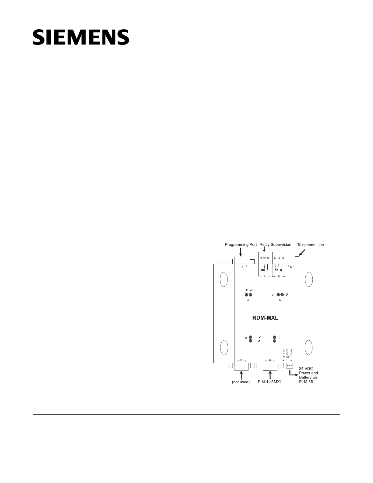
Figure 1
MXL-RDM Module General Configuration
Siemens Building Technologies, Ltd.
Fire Safety & Security Products
2 Kenview Boulevard
Brampton, Ontario
L6T 5E4 Canada
Page 2

POWER REQUIREMENTS
1-MIPLXMrof1-MDR
)ETD-niP9(CtroP232-SR
1-MIPLXM
)niP9(1-MIPfo1BT
25
34
49
52
Typical: 150mA at 24 VDC
Voltage Input: 20-30 VDC
NOTE: Be sure to include the RDM-MXL in
battery calculations.
INSTALLATION
(Refer to Figures 2, 3, 4, and 5)
Remove all system power before installation,
first battery and then AC. (To power up, con-
nect the AC first and then the battery.)
1. The RDM-MXL must be installed in the MXL
enclosure.
2. The Power Terminal of the RDM-MXL must
be connected to the PLM-35. Refer to the
PLM-35 Installation Instructions, P/N 315-
093495.
3. The RDM-MXL is designed to mount on the
MXL-MPFO adapter plate for the MOM-4
position. This bracket has the same footprint
as the MOM-4 and can accommodate 2 RMDMXL modules. An assembly kit is included with
the bracket that contains four nuts and eight
screws. Mount the bracket in the enclosure
with four nuts at the positions labeled “X” in
Figure 2. Refer to Figure 3 for wiring in the
MXL/MXLV enclosure.
The RDM-MXL can also mount to a
SYS3-MPFO adaptor plate for System 3
enclosure (EA-31, EA-32, EA-35) mounting.
4. Connect the D9 RS-232 Port-C of RDM-MXL
to the PIM-1, according to the following
connection chart.
Figure 2
Mounting the RDM-MXL in the
2
MBR-2 or MME-3 Enclosure
Page 3
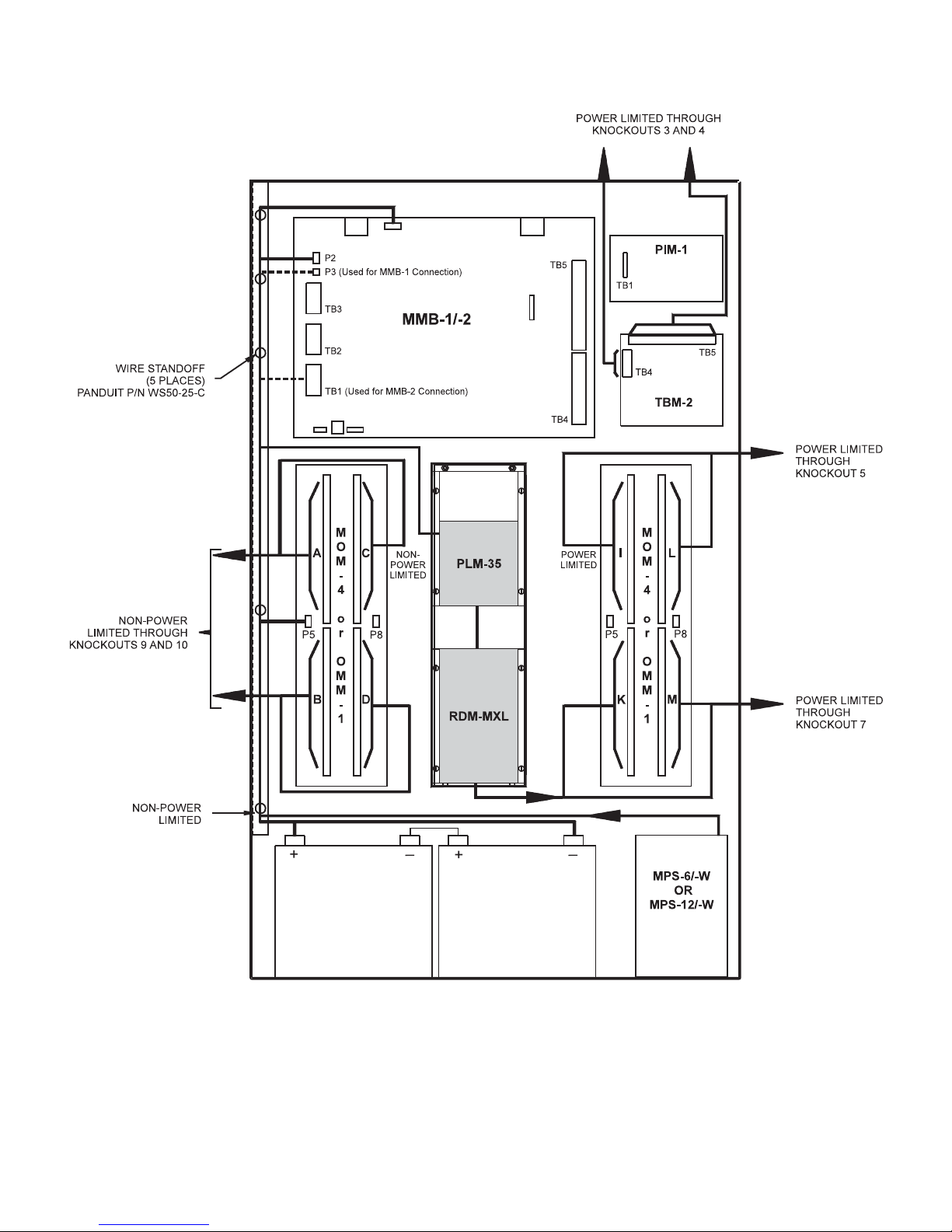
Wiring the RDM-MXL in an MBR-2 or MME-3 Enclosure
Figure 3
3
Page 4
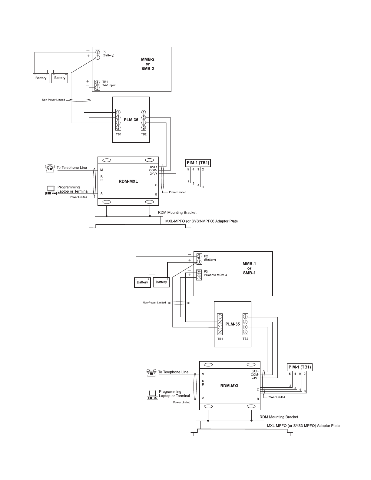
Figure 4
Connecting the RDM-MXL to the MXL/MXL-IQ
System with MMB-2/SMB-2 Main Board
Figure 5
Connecting the RDM-MXL to the MXL/MXL-IQ
System with MMB-1/SMB-1 Main Board
4
Page 5

5. For programming of RDM-1 for MXL PIM-1, a
PC can be temporarily connected to Port 232A of RDM-1 for MXL PIM-1. Note that this is a
straight-through standard RS-232 cable for
laptops.
1-MIPLXMrof1-MDR
AtroP232-SR
)ECD-niP9(
2332
3223
402024
5775
231-TDVLXM
sniP52)52BD(
POTPAL/CP
)TROPMOC-52BD(
sniP52
POTPAL/CP
)TROPMOC-9BD(
niP9
6. If hardware supervision is required, connect
the relay output from the RDM-MXL to a
suitable input on the MXL (software supervision does not require this). There are two
relay sockets located next to the RJ11
connector; these relay sockets are IDENTICAL
and either one can be used. The relays will
energize when Supervision failure is
detected.
7. Connect the 24V DC power source (CZM) to
the supplied connector. The power
connector is next to the RS-232 Port C (See
Figure 1). Pin connections are written on the
board and are as follows:
• PWR (+24 VDC)
• RETURN / COM (0V)
• BATTERY (24V DC)
8. For MXL Connection, refer to Figures 4 and 5.
Connecting to the Telephone Network
1. Connect the telephone line to the RJ11 phone
socket on the RDM-MXL. An FCC Part 68
compliant telephone cord must be used.
2. If the RDM-MXL is mounted so that it
permanently obscures the FCC approval
label on the back of the RDM-MXL, an
additional adhesive label has been supplied.
In the case of the MXL Fire Indicator Panel,
this can be affixed to the door of the MXL
cabinet.
3. This equipment complies with Part 68 and
Part 15 of the FCC rules. On the back of the
RDM-MXL is a label that contains, among
other information, the FCC registration
number and ringer equivalence number
(REN). If requested, this information must be
supplied to the telephone company.
4. The REN is used to determine the quantity of
devices which may be connected to the
telephone line. Excessive RENs on the
telephone line may result in the devices not
ringing in response to an incoming call. In
most, but not all areas, the sum of RENs
should not exceed 5. To be certain of the
number of devices that may be connected to
a line, as determined by the total RENs,
contact the local telephone company.
5. If the RDM-MXL causes harm to the
telephone network, the telephone company
will notify you in advance that temporary
discontinuance of service may be required.
But if advance notice isn’t practical, the
telephone company will notify the customer
as soon as possible. Also, you will be
advised of your right to file a complaint with
the FCC if you believe it is necessary.
6. The telephone company may make changes
in its facilities, equipment, operations or
procedures that could affect the operation of
the equipment. If this happens the telephone
company will provide advance notice in order
for you to make necessary modifications to
maintain uninterrupted service.
5
Page 6

Operation of LEDs:
Each port has a green and a yellow LED. When
the green LED is lit, it means the port is operating normally. When the yellow LED is lit, it
means that the port is not operating properly or
there has been supervision failure on this port. If
both LEDs are off, then this port has been
disabled, is not in use, or is not supervised (For
example, Programming port).
• Port A (Programming and Monitoring Terminal port) and Port C (Connection to MXL):
Green LED indicates supervision is all right.
Yellow LED indicates supervision failure
• Port M (modem):
Green LED indicates modem has
established communication and is
operating properly.
Yellow LED indicates modem failure.
CONFIGURATION OF RDM-1 FOR
MXL PIM-1
1. Power up the RDM-MXL. After approximately
3 seconds, all LEDs on the RDM will turn on.
This allows for programming of the RDM-MXL
using the default configuration. The default
configuration requires that a laptop be
connected to port 232-A using a straightthrough RS-232 cable. A terminal program
such as Procom/Telix or Windows Terminal
using VT100 emulation, can be used with
communication parameters set to 9600, 8, N, 1.
2. If MXL-VDT is being used, set the emulation
to VT100 with communication parameters set
to 9600, 8, N, 1. After programming the
RDM-MXL, reset its emulation and
communication parameters to its previous
setting.
3. Type MENU while all the LEDs are turned on
to start the RDM menu. There is no need to
press <Enter>.
4. This is the only time the RDM-1
programming menu can be accessed.
After entering MENU, you will be prompted to
enter a login password before you can
configure the RDM-MXL. This password
corresponds to the password configured for
your login name. The RDM-MXL is shipped
with the highest level (level 1) password of
PWORD1. After entering the correct
password, the main menu will scroll on the
screen (entering the incorrect password will
exit the programming mode and revert the
RDM-MXL to normal operating mode).
5. Follow the menu options to set the following
information:
Site Name: The location of the MXL fire
alarm panel.
Supervision: This option is used to select
how the RDM-MXL supervises its serial
ports. If the supervision relay is not
connected, then SOFTWARE supervision
can be selected. This selection will allow the
MXL to annunciate a supervision failure.
RDM-MXL Communications Setup: This
submenu sets the communication parameters
to the MXL (Port C) and the monitoring port
(Port A). Make sure that the Port C settings
are the same as the PIM settings in CSG-M.
Also note that for proper supervision, the PIM
should be set for MXL VDT-132.
Dialup Communications Setup: This
submenu selects the settings for the modem
interface between RDM-MXL and RDM-PC.
Dialup Logins: This submenu selects the
LOGIN, the telephone number the RDM-MXL
will call and the password it will verify. Up to
8 different login names can be configured.
Menu Options
• Press the key in brackets to select a
particular menu option (For example, press
<1> to select option 1).
• When entering in letters (For example, the
Sitename or Login name), press the <Enter>
key when finished to save the entry.
• Most other options use the <SPACE BAR> to
step through each available setting for that
option (For example, Baud Rate 1200, 2400,
4800, 9600, 19200).
6
Page 7

• To back out of a menu (and return to the Main
Menu) without saving any changes that were
made, press the <Esc> key or the (q) key.
• The Main Menu is displayed after you type the
correct password from the programming
terminal or PC.
• All Menu options show the factory default for
each setting.
MXL. When failure occurs, the RDM will get
no further events from the MXL.
Relay Rating: 30V, 1A (resistive)
125 VAC, 0.250A (resistive)
Please note that the relays are not set to fail-safe
mode. Both relays will energize when supervision
failure is detected on any supervised ports or on
modem failure.
Main Menu
(1) Sitename
This is displayed to identify the site to which you
are connected. A maximum of 16 characters can
be entered.
(3) RDM-MXL Communication Setup
Options 1-5 set the RDM-1 communication
parameters for MXL communication.
Options 6-A set the RDM-1 communication
parameters for terminal programming and monitoring port.
(2) Supervision Trouble
This option selects how the monitoring port (Port
A) is supervised if a supervised device such as
the MXL-VDT is installed at this port.
Relay Only: When this option is selected,
supervision failure on Port A will transfer the
supervision relays but will not annunciate a
trouble condition on the MXL. This is the
default setting.
Software: When this option is selected,
supervision failure on Port A will transfer the
supervision relays and will annunciate a
Printer Offline trouble-in condition on the
NOTE: BE SURE TO CHECK THE TERMINAL
PROTOCOL SETTING.
(1) For proper MXL supervision, the MXL
protocol should be set for MXL VDT
132. This must also be set in CSG-M
for the PIM-1 port. If No Device is
selected, the RDM will not be
supervised by the MXL.
(2) - (5) For proper communication, set the
MXL communication parameters the
same as the CSG-M settings for the
PIM-1 module.
7
Page 8

(6) The terminal protocol should be set to
XL Graphics or MXL VDT 132 if super-
vision to the terminal (Port A) is required during monitoring. Otherwise, set
it to No Device if this port is going to be
used for programming only.
(7) - (A) This setting should match the communi-
cation parameter of the device to which
this port connects.
The terminal settings can be left at the factory
defaults (indicated above) to allow for connection
of a VDT Terminal or PC for programming
purposes.
NOTE: When the MXL-VDT is connected to Port
A of the RDM-MXL and its supervision is
required, the MXL communication
parameters must match the terminal
communication parameters.
(4) Dialup Communication Setup
(3) - (6) The communications parameters for
Dialup Connections between RDM-MXL
and RDM-PC should not be changed
unless explicitly required.
(7) Show Diagnostics is a special mode
which should only be activated by
technicians in order to resolve modem
communication problems at installation. The default setting is set to NO.
(5) Dialup Logins
(1) The Setup String is for modem com-
munication and it should not be
changed from the factory default
(indicated above).
(2) Dialing is normally set to TONE, but
PULSE dialing can be set if required by
the telephone exchange.
Options (1) to (4) are required for each Login Name.
(1) Login: Name which will be used to
identify who is calling in from RDM-PC.
Login names must be unique for each
entry.
(2) Phone Number: The telephone
number which the RDM-MXL will use
to call back to connect to the RDM-PC.
(3) Password: Once the RDM-MXL has
called back the RDM-PC, this password is used for additional security. It
is also used to identify the person
logging on (using the MENU option
during programming the RDM-MXL).
(4) Dialup Allowed: Setting this option to
Yes allows the RDM-MXL to dial out to
a remote location. Setting this option to
No disables the RDM-MXL from dialing
back. Use the NO setting to temporarily
8
Page 9

disallow access to the system. The
RDM-PC will indicate a logging error
message when a login attempt is made.
Up to 8 login names can be programmed. Use the
Prev and Next options to step through each login
name.
NOTE: Depending on the password you entered
at startup (password entered after typing
MENU), you may not have access to all
login names. For example, if you entered
a password for entry number 7, you can
only access the login details for entry 7
and entry 8. The password for entry
number 1 has full access and can configure details for all logins.
IF TROUBLE IS EXPERIENCED WITH the
RDM-MXL, please contact the Siemens Industry, Inc., Technical Support Department at
(800) 248-7976.
U.S.A. - FCC EQUIPMENT LIMITATIONS:
• An FCC Part 68 compliant telephone cord
must be used.
• This equipment complies with Part 68 and
Part 15 of the FCC rules. On the back of the
RDM-MXL is a label that contains, among
other information, the FCC registration
number and ringer equivalence number (REN).
If requested, this information must be
supplied to the telephone company.
• The REN is used to determine the quantity of
devices which may be connected to the
telephone line. Excessive RENs on the
telephone line may result in the devices not
ringing in response to an incoming call. In
most, but not all areas, the sum of RENs
should not exceed 5. To be certain of the
number of devices that may be connected to
a line, as determined by the total RENs,
contact the local telephone company.
• If the RDM-MXL causes harm to the
telephone network, the telephone company
will notify you in advance that temporary
discontinuance of service may be required.
But if advance notice isn’t practical, the
telephone company will notify the customer
as soon as possible. Also, you will be advised
of your right to file a complaint with the FCC
if you believe it is necessary.
• The telephone company may make changes
in its facilities, equipment, operations or
procedures that could affect the operation of
the equipment. If this happens the telephone
company will provide advance notice in order
for you to make necessary modifications to
maintain uninterrupted service.
9
Page 10

INDUSTRY CANADA - EQUIPMENT ATTACHMENT LIMITATIONS:
NOTICE: The Industry Canada label identifies certified equipment. This certification means that the
equipment meets telecommunications network protective, operational and safety requirements as
prescribed in the appropriate Terminal Equipment Technical Requirements document(s). The Department does not guarantee the equipment will operate to the user’s satisfaction.
Before installing this equipment, users should ensure that it is permissible to be connected to the
facilities of the local telecommunications company. The equipment must also be installed using an
acceptable method of connection. The customer should be aware that compliance with the above
conditions may not prevent degradation of service in some situations.
Repairs to certified equipment should be coordinated by a representative designated by the supplier.
Any repairs or alterations made by the user to this equipment, or equipment malfunctions, may give the
telecommunications company cause to request the user disconnect the equipment.
Users should ensure for their own protection that the electrical ground connections of the power utility,
telephone lines and internal metallic water pipe system, if present, are connected together. This precaution may be particularly important in rural areas.
Caution: Users should not attempt to make such connections themselves, but should contact appropriate electric inspection authority, or electrician, as appropriate.
NOTICE: The Ringer Equivalence Number (REN) assigned to each terminal device provides an
indication of the maximum number of terminals allowed to be connected to a telephone interface. The
termination on an interface may consist of any combination of devices subject only to the requirement
that the sum of the Ringer Equivalence Numbers does not exceed 5.
10
Page 11

11
Page 12

Siemens Industry, Inc.
Building Technologies Division
Florham Park, NJ
P/N 315-096325-4
Siemens Building Technologies, Ltd.
Fire Safety & Security Products
2 Kenview Boulevard
Brampton, Ontario
L6T 5E4 Canada
 Loading...