

Page 1

SIPART PS2
6DR50xx
6DR51xx
6DR52xx
6DR53xx
Edition 10/2006
Manual
Electropneumatic Positioner for
Linear and Part-Turn Actuators
SIPART PS2 Manual
A5E00074630- -06
1
Page 2

Copyright e Siemens AG 2006 All rights reserved
Disclaimer of Liability
The reproduction, transmission or use of this document or its contents is not permitted without express written authority. Offenders will be liable for
damages. All rights, including rights created by patent grant or registration of a utility model or design,
are reserved.
Siemens AG
Bereich Automatisierungs-- und Antriebstechnik
Geschäftsgebiet Prozessinstrumentierung-- und
Analytik
D--76181 Karlsruhe
We have checked the contents of this manual for
agreement with the hardware and software described. Since deviations cannot be precluded entirely,
we cannot guarantee full agreement. However, the
data in this manual are reviewed regularly and any
necessary corrections included in subsequent editions. Suggestions for improvement are welcomed.
e Siemens AG 2006
Technical data subject to change.
Trademarks
SIMATIC, SIPART, SIREC, SITRANS are registered trademarks of Siemens AG.
Third parties using for their own purposes any other names in this document which refer to trademarks might infringe upon the rights of the trademark owners.
SIPART PS2 Manual
2
A5E00074630- -06
Page 3

Contents
0 Information for the Operator 5.............................................
0.1 General information 5...........................................
0.2 Classification of Safety Related Notices 6.........................
0.3 Qualified Personnel 7...........................................
0.4 Use as intended 9..............................................
0.5 Technical Documentation 9......................................
0.6 Warranty Information 9..........................................
0.7 Delivery Notes 10...............................................
0.8 Standards and Regulations 10....................................
1 Introduction 11............................................................
1.1 General information about the positioner 1 1.........................
2 Design and Method of Operation 15........................................
2.1 Overview 15....................................................
2.2 Design name plate 17............................................
2.3 Instrument Components 17.......................................
2.3.1 Motherboard 18.................................................
2.3.2 Electrical Connections 18.........................................
2.3.3 Pneumatic Connections 19.......................................
2.3.4 Mounting Kit 22.................................................
2.3.5 Purge air switching (not in the explosion proof version) 22............
2.3.6 Restrictors 22...................................................
2.4 Method of Operation 23..........................................
2.5 HART-function 26...............................................
2.6 State as supplied 26.............................................
2.7 Installation of options modules 27.................................
2.7.1 Installation of options modules in normal and intrinsically
safe versions 27................................................
2.7.2 Installation of options modules in explosion proof version 29..........
2.7.3 Iy-module 31...................................................
2.7.4 Alarm module 32................................................
2.7.5 SIA module 33..................................................
2.7.6 Mechanical limit switch module 35.................................
2.7.7 EMC filter module 38............................................
2.7.8 Accessories 39.................................................
3 Preparing for Operation 41.................................................
3.1 Instrument identification (type key) 41..............................
3.2 Dimensional drawings 41.........................................
3.3 Assembly 43....................................................
3.3.1 Instructions for using positioners in a wet environment 44.............
3.3.2 Instructions for using positioners which are exposed to strong
accelerations or vibrations 46.....................................
3.3.3 Mounting kit “linear actuator” 6DR4004-8V and 6DR4004-8L 49.......
3.3.4 Assembly procedure (see figure 3-7, page 51) 50....................
SIPART PS2 Manual
A5E00074630- -06
3
Page 4

3.3.5 Mounting kit “part-turn actuator” 6DR4004-8D 52....................
3.3.6 Assembly procedure (see figure 3-8 and figure 3-9) 53...............
3.4 Electrical Connection 57..........................................
3.4.1 Connection in non-intrinsically safe and explosion proof version 59.....
3.4.2 Connection in intrinsically safe version 62...........................
3.4.3 Connection in type of protection “n” version 68......................
3.5 Pneumatic Connection 71........................................
3.6 Commissioning 72...............................................
3.6.1 Preparations for linear actuators 73................................
3.6.2 Automatic initialization of linear actuator 74.........................
3.6.3 Manual initialization of linear actuator 76............................
3.6.4 Preparations for part-turn actuator 79..............................
3.6.5 Automatic initialization of part-turn actuator 79......................
3.6.6 Manual initialization of part-turn actuators 81........................
3.6.7 Automatic initialization (structograms) 82...........................
3.7 Copying initialization data (positioner exchange) 87..................
4 Operation 89..............................................................
4.1 Display 89......................................................
4.2 Input keys 89...................................................
4.3 Operating modes 92.............................................
4.4 Parameters 95..................................................
4.5 Diagnostics 122..................................................
4.5.1 Diagnostic display 122............................................
4.5.2 Meaning of the diagnostic values 123...............................
4.5.3 Online diagnostics 131............................................
4.5.4 Fault correction 136..............................................
4.6 Meaning of the other display text 139...............................
4.7 Optimizing the controller data 143..................................
5 Service and Maintenance 145................................................
6 Technical Data 147.........................................................
7 Scope of Delivery 153.......................................................
7.1 Scope of delivery of standard controller 154..........................
7.2 Scope of delivery of options 154....................................
7.3 Scope of delivery of accessories 155................................
7.4 List of Spare Parts 156............................................
8 Index 158..................................................................
9 Appendix 160..............................................................
9.1 Literature and catalogs 160........................................
4
SIPART PS2 Manual
A5E00074630- -06
Page 5

Information for the Operator
Information for the Operator
Dear customer,
Please read this manual before starting work!
It contains important information and data which, when observed,
ensure full availability of the equipment and save service costs. This
simplifies handling of this control instrument considerably and provides
accurate measuring results.
You have purchased an instrument which can be installed in various
configurations:
S SIPART PS2 without Ex-protection in a metal- or plastic housing.
S SIPART PS2 with EEx ia/ib-protection in a metal- or plastic hous-
ing.
S SIPART PS2 EEx d in a pressurized explosion proof housing
This manual takes each of these possibilities into consideration.
Any differences between the devices are indicated specially.
Scope of delivery, see chapter 7, page 153.
0
0.1 General information
The product described in this manual left the factory in a perfectly safe
and tested condition. To maintain this condition and to achieve perfect
and reliable operation of this product, it must only be used in the way
described by the manufacturer. Successful and safe operation of this
equipment is dependent on proper handling, installation, operation and
maintenance.
SIPART PS2 Manual
A5E00074631- -06
5
Page 6

Information for the Operator
This manual contains the information required for use as intended of
the product it describes. It is addressed to technically qualified personnel specially trained or having relevant knowledge of instrumentation
and control technology, hereafter called automation technology.
Familiarity with and proper technical observance of the safety notes
and warnings contained in this manual are essential for safe installation
and commissioning and for safety in operation and maintenance of the
product described. Only qualified personnel as defined in Chapter 0.3
has the necessary specialist knowledge to interpret the general safety
notes and warnings given in this document in specific cases and to
take the necessary action.
The documentation supplied with the instrument is listed in Chapter 0.5.
This manual is not a permanent part of the scope of supply. For reasons
of clarity, it does not contain every detail about every version of the
product described and cannot take every eventuality in installation, operation, maintenance and use in systems into account. If you require
further information or if problems occur that have not been dealt with in
sufficient detail in this document, please request the required information from your local Siemens office or the office responsible for you.
Functionality, commissioning and operation are described in this
manual.
Please pay special attention to the Warning and Note texts. These are
separated from the remaining text by horizontal lines and specially
marked with symbols (see Chapter 0.2).
0.2 Classification of Safety Related Notices
This manual contains notices which you should observe to ensure your
own personal safety, as well as to protect the product and connected
equipment. These notices are highlighted in the manual by a warning
triangle and are marked as follows according to the level of danger:
DANGER
!
!
indicates an immenently hazardous situation which, if not avoided, will
result in death or serious inury .
WARNING
indicates a potentially hazardous situation which, if not avoided, could
result in death or serious injury .
SIPART PS2 Manual
6
A5E00074631- -06
Page 7

Information for the Operator
CAUTION
!
used with the safety alert symbol indicates a potentially hazardous situation which, if not avoided, may result in minor or moderate injury.
CAUTION
used without the safety alert symbol indicates a potentially hazardous
situation which, if not avoided, may result in property damage.
NOTICE
indicates a potential situation which, if not avoided, may result in an
undesirable result or state.
.
NOTE
highlights important information on the product, using the product,
or part of the documentation that is of particular importance and that
will be of benefit to the user.
0.3 Qualified Personnel
The result of unqualified intervention in the instrument or nonobservance of the warnings given in this manual or on product labels can be
severe personal injury and/or serious material damage. Therefore only
properly qualified personnel must make changes and settings in the
instrument.
For the purpose of the safety information in this manual and on the
product labels, qualified personnel are those who
S in the case of ex-proof equipment, are trained, instructed or
authorized to perform work on electrical circuits of equipment
subject to explosion hazard.
S if they are configuration personnel, are familiar with the safety
concepts of automation technology
SIPART PS2 Manual
A5E00074631- -06
S if they are operating personnel, have been instructed in the handling
of automation equipment and know the content of this manual
relating to operation
S if they are commissioning and/or service personnel, are trained to
repair such automation equipment and authorized to energize,
de-energize, clear ground and tag circuits and equipment according
to safety engineering standards.
S and instructed additionally in first aid
7
Page 8

Information for the Operator
WARNING
!
The instrument must only be installed and commissioned by qualified
personnel.
The device may be used solely for the purposes described in this
manual.
The instrument is designed for connection to functional and safety
extra low voltage.
Electrical safety depends only on the power supply equipment.
Pneumatic actuators exert considerable positioning forces. The safety
precautions of the actuator used must therefore be scrupulously
observed during installation and commissioning in order to prevent
injuries.
We explicitly draw your attention to the necessity of observing safety
regulations regarding operation in zones subject to explosion hazard,
if applicable.
The specifications of the examination certificate valid in your country
must be observed. Laws and regulations valid in your country must be
observed for the electrical installation in explosions hazardous areas.
In Germany these are for example:
-- Working reliability regulations
-- Regulations for installing electrical equipment in hazardous areas,
DIN EN 60079-14 (in the past VDE 0165, T1).
It should be checked whether the available power supply, insofar as
this is required, is compliant with the power supply specified on the
rating plate and specified in the examination certificate valid in your
country.
Take care to avoid electrostatic discharges within the hazardous area,
such as can arise if a dry cloth is used to clean the positioner in the
plastic housing.
Devices with the protection type “flameproof enclosure” may only be
opened when the power is off.
WARNING
!
Devices with the protection type “intrinsically safe” lose their certification as soon as they are operated with circuits that do not conform to
the specifications laid down in the examination certificate valid in your
country.
The successful and safe operation of this equipment is dependent
upon its proper handling, installation, operation and maintenance.
SIPART PS2 Manual
8
A5E00074631- -06
Page 9

WARNING
!
The device may not be operated while the leaflets are in the housing.
0.4 Use as intended
Use as intended for the purpose of this manual means that this product
must only be used for the applications described in the technical description (see also Chapter 3 of this manual).
The product described in this manual has been developed, manufactured, tested and documented observing the relevant safety standards.
If the handling rules and safety information for configuration, installation, use as intended and maintenance are observed, there is normally
no danger with regard to material damage or for the health of personnel. Extra low voltages that are connected must be fed in by safe isolation.
Information for the Operator
0.5 Technical Documentation
The operating instructions are a constituent part of the enclosed CD
“sipartp ps2 POSITIONERS” (order number A5E00214567) and is
available on the Internet at:
www.siemens.com/sipartps2
Click on “More Info” and --> “Instructions and Manuals”.
On the enclosed CD, you will find an extract of the catalog FI 01 “Field
devices for process automation” with the current order data. The entire
FI 01 catalog is also available at the above Web address.
0.6 Warranty Information
We should like to point out that the content of this manual is not part of
and does not modify a previous or current agreement, undertaking or
legal relationship. Siemens is bound solely by the contract of sale,
which also contains the complete and exclusive warranty. The contractual warranty conditions are neither extended nor restricted by this
document.
SIPART PS2 Manual
A5E00074631- -06
9
Page 10

Information for the Operator
0.7 Delivery Notes
The scope of delivery is listed on the dispatch papers accompanying
the delivery in accordance with the valid contract of sale.
When you open the packaging please observe the information on the
packaging. Check that the delivery is complete and undamaged.
If possible, compare the order number on the rating plates with the ordering data.
For the scope of delivery please see Chapter 7, page 153.
0.8 Standards and Regulations
As far as possible, the harmonized European standards were used to
specify and manufacture this equipment. If harmonized European standards have not been applied, the standards and regulations of the Federal Republic of Germany apply (see also the Technical Data in Chapter 6, page 147).
If this product is used outside the area of applicability of these standards and regulations, please observe the standards and regulations in
force in the country where the product is operated.
10
SIPART PS2 Manual
A5E00074631- -06
Page 11

Introduction
Introduction
1.1 General information about the positioner
The positioner is used to adjust and control pneumatic actuators.
The controller operates electropneumatically with compressed air as an
energy supply.
Purpose
For example, the positioner can be used to control valves as follows:
S with linear actuator (figure 1-1, page 13) or
S with part-turn actuator VDI/VDE 3845 (figure 1-2, page 13)
Different mounting types are available for linear actuators:
S NAMUR or IEC 534
S integrated mounting to ARCA
1
Versions
Housing
S integrated mounting to SAMSON (non-explosion-proof version)
This means the positioner can be installed and operated on all common
actuator systems.
The positioner is available for the following actuators:
S double-acting and
S single-acting
For following applications:
S potentially explosive or
S not potentially explosive applications.
The electronics with display, position feedback and valve block are integrated in the housing.
The housing is available in three versions:
S Plastic housing for single and double-acting actuators
S Metal housing for single-acting actuators
S Explosion proof housing for single and double-acting actuators
SIPART PS2 Manual
A5E00074631- -06
11
Page 12

Introduction
Degree of
protection
Explosion
Protection
SIL applications
Options
The device is designed with IP66/NEMA4x degree of protection.
The intrinsically safe version can be used in hazardous areas in zone 1
or zone 2.
The explosion proof version can be used in hazardous areas in zone 1
or zone 2.
The version with the type of protection “n” can be used in hazardous
areas of zone 2.
The SIPART PS2 positioners in the variations 6DR501*, 6DR511*,
6DR521* and 6DR531* (i.e. with 0/4 up to 20 mA control signal in the
single-acting design) are also suitable for positioning on fittings with
pneumatic actuators, which satisfy the special requirements for safety
devices up to SIL 2 to IEC 61508/ IEC 61511-1. For this, the SIL safety
instructions (see “SIPAR T PS2 SIL safety manual” A5E00442120) must
be followed.
The positioner can be expanded with various options modules (chapter 2.7, page 27). The following modules are available in all:
S
-module: Two-wire current output 4 to 20 mA for position feedback
Iy
S Alarm module: 3 digital outputs and 1 digital input
Accessories
Environmental
Protection
S SIA module: one digital output for fault messages, two digital out-
puts for limit value alarms
S Manometer block: 2 or 3 manometers for single and double-acting
positioners
S Connection block (NAMUR) for safety valve block
S Mounting kits for linear and part-turn actuator
For decentralized installation of the positioner and position sensor:
S External position detection system
S Non-Contacting Position Sensor (NCS)
Only environmentally friendly materials have been used in the construction of the positioner.
The technical manual is printed on chlorine-free bleached paper.
12
SIPART PS2 Manual
A5E00074631- -06
Page 13
Introduction
1
2
3
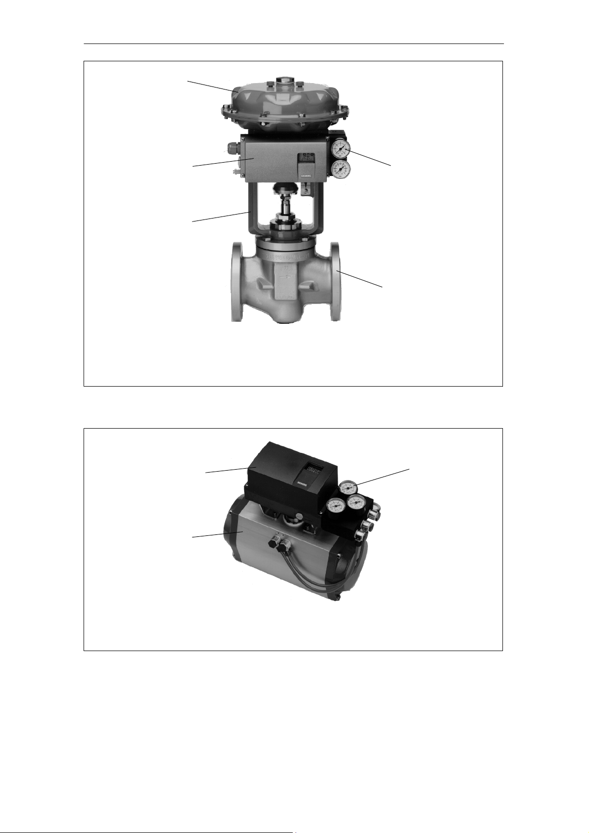
1 Actuator
2 Positioner, single-acting in metal housing
3 Lantern
4 Manometer block, single-acting
5Valve
Figure 1-1 Positioner mounted on linear actuator (single-acting)
4
5
1
2
1 Positioner double-acting in plastic housing
2 Part-turn actuator
3 Manometer block, double-acting
Figure 1-2 Positioner mounted on part-turn actuator (double-acting)
SIPART PS2 Manual
A5E00074631- -06
3
13
Page 14
Introduction
1
2
4
3
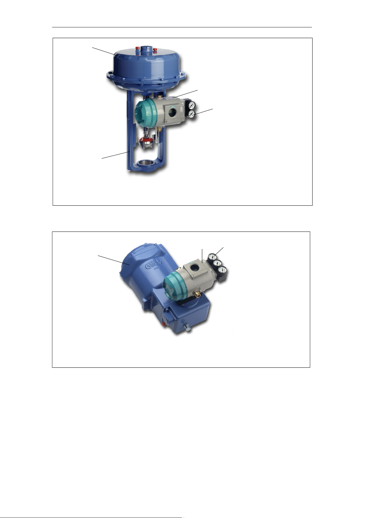
1 Actuator
2 Positioner, single-acting in explosion proof housing
3 Lantern
4 Manometer block, single-acting
Figure 1-3 Explosion proof version of the positioner mounted on linear actuator (single-acting)
1
3
2
1 Positioner double-acting in explosion proof housing
2 Part-turn actuator
3 Manometer block, double-acting
Figure 1-4 Explosion proof version of the positioner mounted on part-turn actuator (double-acting)
Table 1-1
14
SIPART PS2 Manual
A5E00074631- -06
Page 15

Design and Functional Principle
Design and Method of Operation
The following chapter describes the mechanical and electrical design,
the instrument components and method of operation of the positioner.
2.1 Overview
Introduction
The electropneumatic positioner forms a control system in connection
with an actuator. The current position of the actuator is detected by a
servo potentiometer and fed back as actual value x. The setpoint and
actual value are output simultaneously on the display.
The setpoint w is formed by a current fed to the positioner which at
the same time serves to supply the positioner in two-wire operation.
In 3/4-wire operation the supply comes from a 24 V voltage input.
The positioner operates as a predictive five-point switch by the output
variable ±∆y of which the integrated actuating valves are controlled with
pulse length modulation.
2
These actuating signals cause fluctuations in pressure in the actuator
chamber(s) and thus adjustment of the actuator until the control error is
zero.
Operation (manual) and configuration (structuring, initialization and
parameterization) is effected by three keys and a display with the housing cover removed.
The standard controller has one digital input (DI1). This can be configured individually and can be used for blocking the operating modes for
example.
With the I
as a two wire signal I
In addition the actuator can be monitored for two programmable limit
values which respond on exceeding or dropping below the stroke or
angle of rotation.
The limit value alarms are output by the alarm option module which can
monitor and report the function of the positioner and the actuator additionally through a fault message output. The value of the control difference dependent on the travel time is monitored in automatic mode. The
fault signal is always set when the control error cannot be leveled after
a certain time because for example the valve is blocked or the mains
pressure is insufficient. The three digital outputs are implemented as
semiconductor outputs and are error self-reporting, i.e. the outputs re-
-option module, the current actuator position can be output
y
=4to20mA.
y
SIPART PS2 Manual
A5E00074631- -06
15
Page 16

Design and Functional Principle
spond even when the power supply fails or the electronics are defective.
The actuator can also be blocked or driven to its final positions depending on the configuration for example by an external event via a digital
input (DI2) on the alarm module.
If you require electrically independent limit value messages from the
standard controller, you will have to use the SIA module with the slot
initiators instead of the alarm module.
Communication with the controller is possible via the optional HART
interface.
To be able to use the positioner with a variety of different part-turn and
linear actuators, it has a friction clutch and switchable gearing.
The switchable gearing allows you to adjust the positioner for small and
large lifts. You can switch using the yellow switch (8, Fig. 2-11, page 28)
between 33_ (as delivered) and 90_.
The friction clutch (8, Fig. 2-1 1, page 28) allows you to set the working
range, particularly for linear actuators, after installation. You thus do not
have to ensure symmetrical mounting during the installation.
As it is not allowed to open the housing of an explosion-proof version in
a potentially explosive atmosphere, the shaft has an externally fitted,
additional friction clutch (8, Fig. 2-12, page 31).
NOTICE
for the explosion-proof version:
Only adjust the outer friction clutch (8, Fig. 2-12, page 31). The internal
friction clutch (8, Fig. 2-1 1 page 28) is fixed and, for the explosionproof version, must not be adjusted.
16
SIPART PS2 Manual
A5E00074631- -06
Page 17
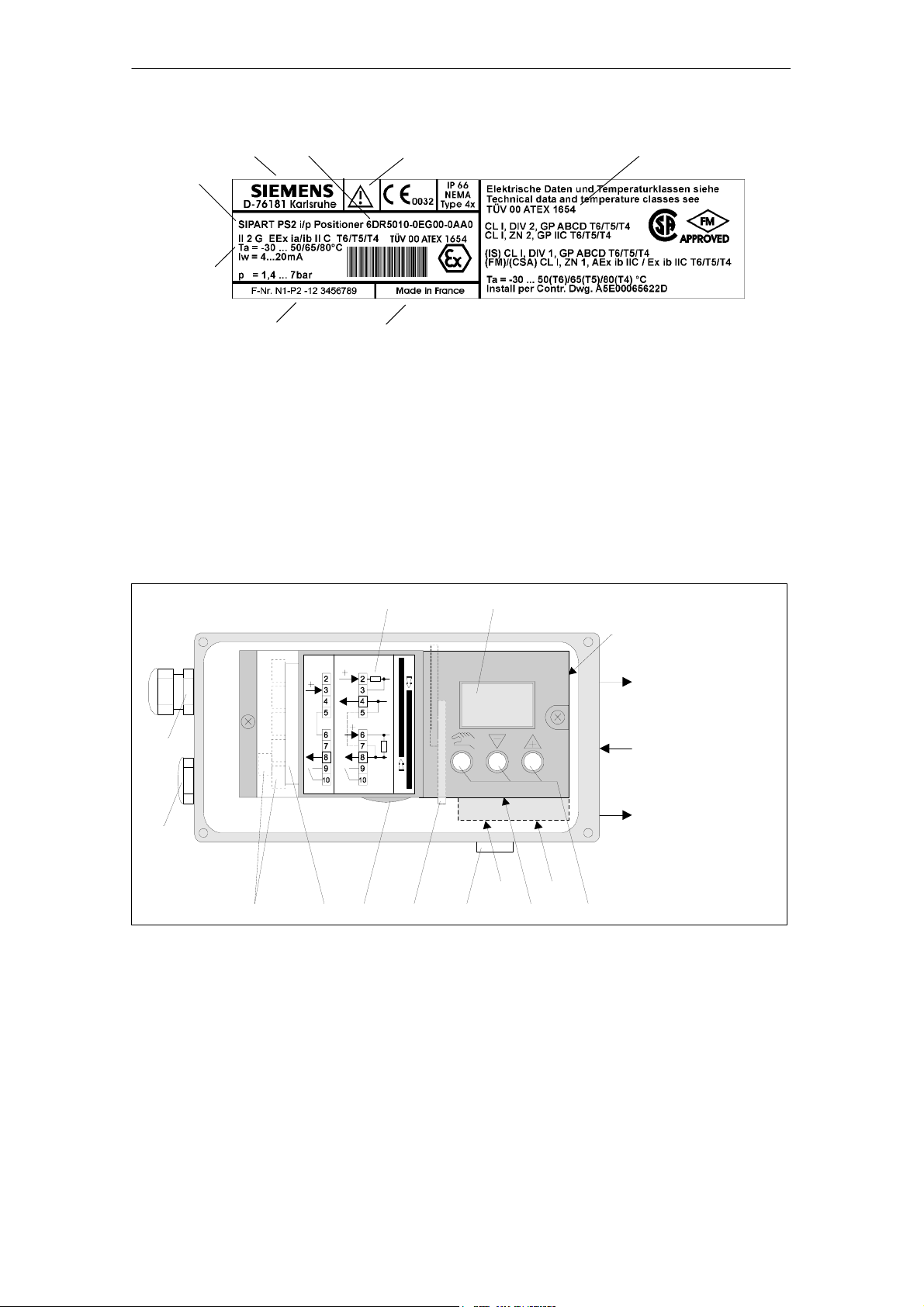
2.2 Name plate design
Design and Functional Principle
(2)
(8)
(3)
(4)
(5)
(6)
(1) Order number (5) Serial number
(2) Manufacturer (6) Place of manufacture
(3) Product name (7) Protection class
(4) Technical data (8) Observe manual
Figure 2-1 Design name plate, example with protection class EEx ia/ib
2.3 Instrument Components
(7)(1)
314
90°
DI1
O
33
O
90
13
3/4 W2W
4...20 mA
0/4...20 mA
33°
12
6.1 6.2
7891011
1 Input: Supply air 7 Silencer
2 Output: Actuating pressure Y1 8 Transmission ratio selector
3 Display 9 Adjusting wheel for frichtion clutch
4 Output: Actuating pressure Y2
5 Operating keys 12 Dummy plug
6 Restrictor 13 Screw-type cable gland
6.1 Restrictor Y1 14 Terminal plate on cover
6.2 Restrictor Y2
*)
in double-acting actuators
*)
*)
10 Terminals options modules
15 Purging air switch
56
15
2
1
4
Figure 2-2 View of the positioner in normal version (cover open)
SIPART PS2 Manual
A5E00074631- -06
17
Page 18

Design and Functional Principle
9
1
10
3
---++
10
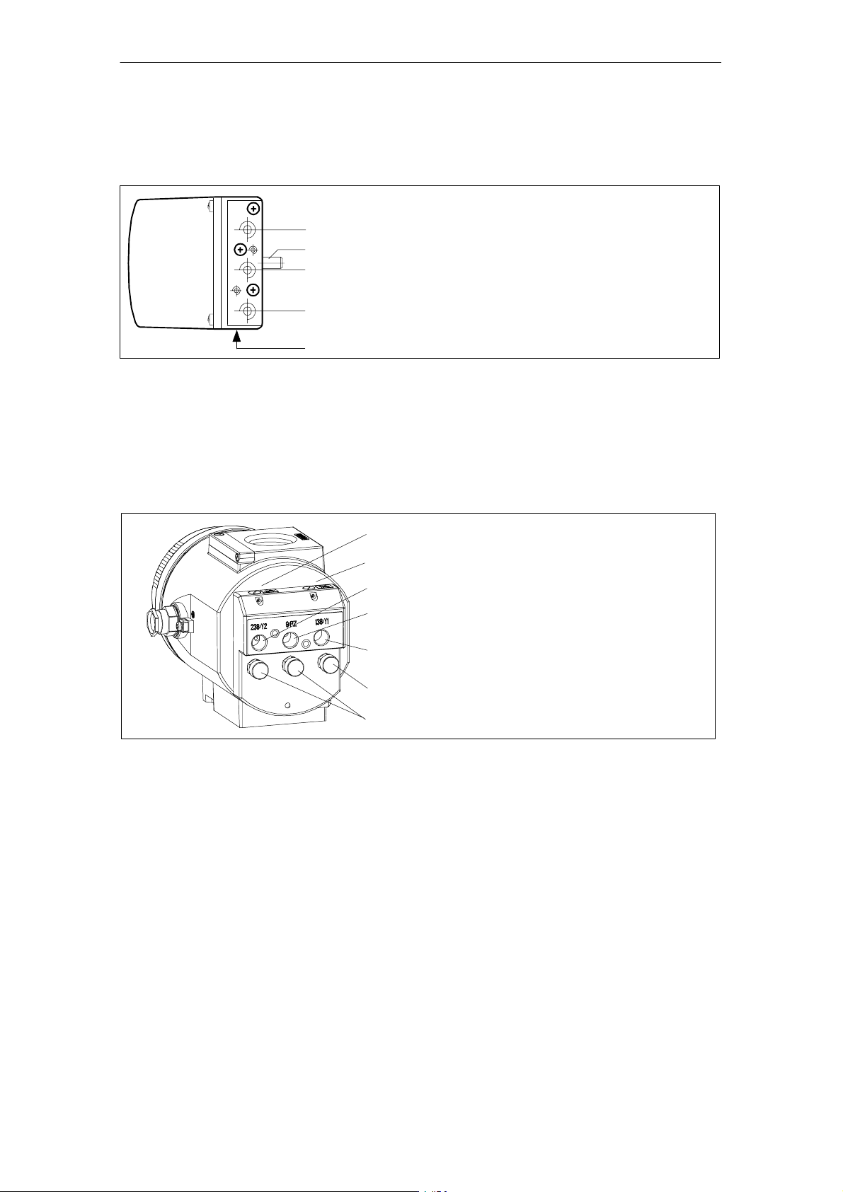
1 Input: Supply air 7 Transmission ratio selector
2 Output: Actuating pressure Y1 (only possible with positioner open)
3 Display 8 Adjusting wheel for friction clutch
4 Output: Actuating pressure Y2
5 Operating keys 10 Terminals options modules
6.1 Restrictor Y1 12 Safety catch
6.2 Restrictor Y2
*)
in double-acting actuators
*)
*)
2121
6.1
138238 9
6.2
45
9 Terminals standard controller
7
8
Figure 2-3 View of the explosion proof version of the positioner
2.3.1 Motherboard
The motherboard contains all the electronic elements such as the CPU,
memory, A/D converter. It also contains the display and the operating
keys.
In addition, the terminal strips for connecting the options modules are
also on the motherboard.
2.3.2 Electrical Connections
The terminals of the standard controller, the Iy- and alarm-option module are arranged at the left-hand front edges and offset against each
other in staircase form.
A module cover protects the modules from being pulled out and prevents incorrect installation.
18
SIPART PS2 Manual
A5E00074631- -06
Page 19
2.3.3 Pneumatic Connections
The pneumatic connections are on the right hand side of the positioner
(figure 2-4 and figure 2-5).
1
2
3
4
5
1 Actuating pressure Y1 in single- and double-acting actuators
2 Feedback shaft
3 Supply air P
4 Actuating pressure Y2 in double-acting actuators
5 Exhaust air output E with silencer on the bottom of the instrument
z
Design and Functional Principle
Figure 2-4 Pneumatic connection in normal version
1
2
3
4
5
6
7
1 Restrictor Y2 *) 5 Actuating pressure Y1
2 Restrictor Y1 6 Exhaust air output E
3 Actuating pressure Y2 *) 7 Housing ventilation (2x)
4 Supply air PZ
*)
in double-acting actuators
Figure 2-5 Pneumatic connection in explosion proof version
SIPART PS2 Manual
A5E00074631- -06
In addition, there are pneumatic connections on the back of the positioner for integrated installation in single-acting linear actuators.
S Actuating pressure Y1
S Exhaust air output E (not in explosion proof version)
In the ex-factory state, these connections are sealed by screws
(see figure 3-1, page 41, figure 3-3, page 42 and figure 3-4, page 43).
19
Page 20

Design and Functional Principle
The exhaust air output E can be provided for supplying dry instrument
air to the tapping chamber and spring chamber to prevent corrosion.
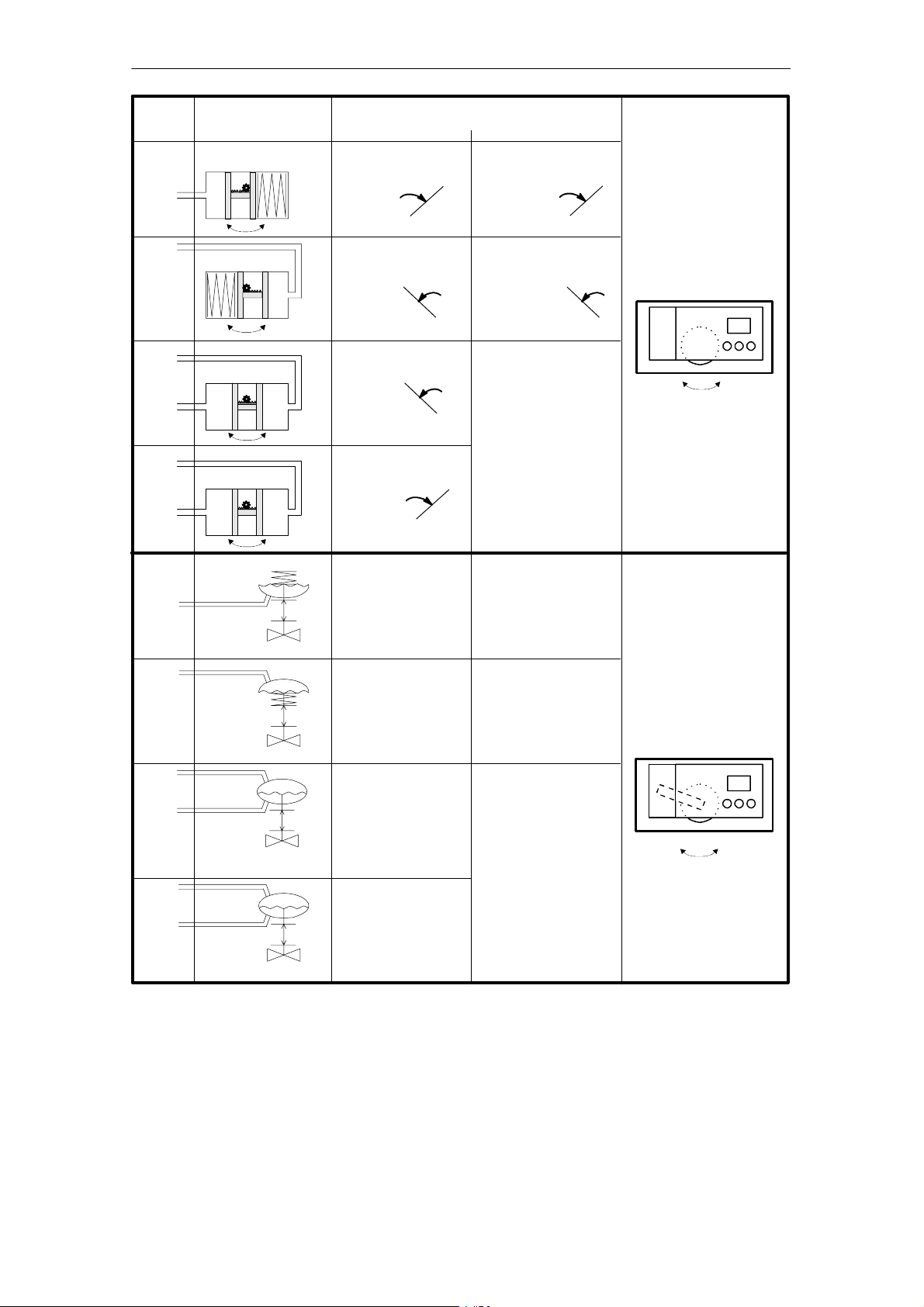
Figure 2-6, page 21 shows the pneumatic connection variants for the
different actuator types, the positioning action and the safety position
after power failure.
20
SIPART PS2 Manual
A5E00074631- -06
Page 21
Design and Functional Principle
Positioning
pressure
Connection
Y1
Y1
Y2
Y1
Y1
Y2
Closed
Closed
Actuator type
Open
Open
OpenClosed
OpenClosed
Safety position after power failure
electrical pneumatic
Closed Closed
Open Open
Open
Last position
(before power
failure)
Closed
In part-turn actuators the
direction of rotation
counterclockwise looking
onto the actuating shaft of
the valve is usually defined
as “Open”.
Open
Closed
Y1
up
Down Down
down
Y1
up
down
Up Up
Y2
Y1
up
down
Up
Y1
Y2
up
down
Down
Figure 2-6 Pneumatic connection positioning
Last position
(before power
failure)
up down
SIPART PS2 Manual
A5E00074631- -06
21
Page 22
Design and Functional Principle
2.3.4 Mounting Kit
The positioner can be mounted on almost all actuators with the appropriate mounting kit.
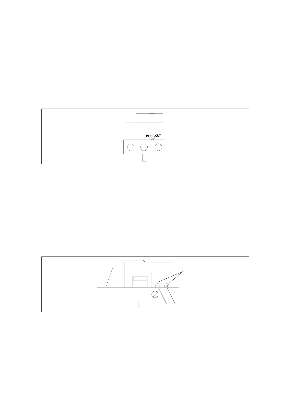
2.3.5 Purge air s witch in g (not in the explosion proof version)
The purge air switch is accessible above the pneumatic terminal strip
with the housing open (figure 2-7). In the IN position the inside of the
housing is purged with very small amounts of clean, dry instrument air.
In the OUT position the purge air is fed directly to the outside air.
Figure 2-7 Purge air switch on the valve block, view of the positioner onto pneumatic connection side
with cover open
2.3.6 Restrictors
In order to achieve travel times of > 1.5 s in small actuators, the air rate
can be reduced with the restrictors Y1 and Y2 (figure 2-8, in explosion
proof version, see figure 2-5, page 19). By turning to the right the air
rate is reduced up to shutting off. To set the restrictors it is advisable to
close them and then open them slowly (see initialization RUN3).
In the case of double-acting valves make sure that both chokes are set
approximately equal.
Hexagon socket 2.5 mm
Y1 Y2
Figure 2-8 Restrictors
22
SIPART PS2 Manual
A5E00074631- -06
Page 23

2.4 Method of Operation
The electropneumatic positioner SIPAR T PS2 forms a control circuit
with the pneumatic actuator in which the actual value x is the position
of the actuator bar in linear actuators or the position of the actuator
shaft in part-turn actuators and the command variable w is the
actuating current of a controller or a manual control station of 4 to
20 mA.
The stroke or part-turn movement of the actuator is transferred by the
appropriate mounting accessories, the feedback shaft and a play-free
switchable gearwheel to a high quality conductive plastic potentiometer
and to the analog input of the microcontroller. The current position can
also be preset for the positioner via an external sensor. The detection
of the stroke or rotation andle is performed by a non-contacting position sensor (Non Contacting Position Sensor) directly at the actuator.
This may correct the angle error of the stroke tap, compares the
potemtiometer voltage as actual value x with the setpoint w fed in at
the terminals 3 and 7 and calculates the manipulated variable
increments Δy. Depending on the size and direction of the control
error (x-w) the piezo-controlled supply air or exhaust air valve is
opened. The volume of the actuator integrates the positioning
increments to actuating pressure y open which moves the actuator bar
or actuator shaft approximately proportionally. These positioning
increments change the actuating pressure until the control error
becomes zero.
Design and Functional Principle
The pneumatic actuators are available in single and double-acting
versions. Only one pressure chamber is aerated or deaerated in the
single-acting version. The resulting pressure operates against a spring.
In the double-acting version, two pressure chambers are counteractive.
In this case the one volume is deaerated when the other volume is
aerated. See the block diagram figure 2-10, page 25.
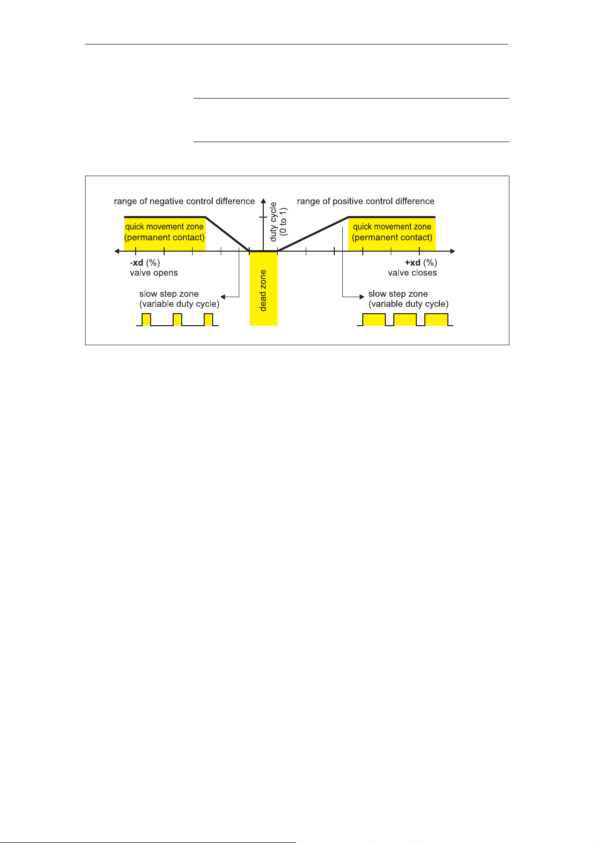
The control algorithm is an adaptive predictive five-point switch
(see figure 2-9, page 24).
The valves are controlled with continuous contact at large control errors
(fast step zone). At medium control errors the valve is controlled by
pulse length modulated pulses (short step zone).
No actuating pulses are output in the small control error zone (adaptive
dead zone). The dead zone adaptation and the continuous adaptation
of the minimum pulse lengths in automatic operation cause the best
possible control accuracy to be achieved at the lowest switching frequency. The start parameters are determined during the initialization
phase and stored in a non-volatile memory. These are basically the real
travel with the mechanical limit stops, the travel times, the size of the
dead zone etc.
In addition the number of fault messages, changes in direction and the
number of strokes are determined and stored every 15 minutes during
operation. These parameters can be read out and documented by the
communication programs such as PDM and AMS. Conclusions as to
the wear on the fitting can be drawn (diagnostic function) especially by
comparing the old value with the currently determined values.
SIPART PS2 Manual
A5E00074631- -06
23
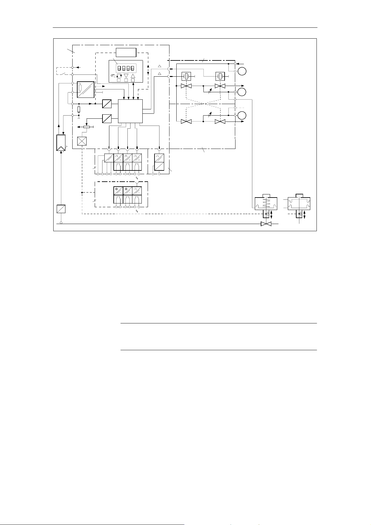
Page 24
Design and Functional Principle
Figure 2-10, page 25 shows the block diagrams for single- and doubleacting actuators with the linear actuator as an example.
.
Figure 2-9 Method of operation five-point switch
NOTE
The exhaust air valve is always open when there is no current.
24
SIPART PS2 Manual
A5E00074631- -06
Page 25
Design and Functional Principle
1
BE1
I
I
y
0
+
x
W+
W-
3 V
W
+U
_
W
x
0
6
BE2
7
+5 V
A
A
2
+24 V
D
D
HART
_
Micro-
controller
A1 A2
II
A1 A2
3
_
y
y
+
+
U
U
I
5
4
Zuluft
Supply air
p
Z
Exhaust air
Abluft
p
1
p
p
p
2
Abluft
Exhaust
air
1
2
stroke
9
p
2
p
1
stroke
8
p
1
1 Motherboard with microcontroller and input circuit
2 Control panel with LC-display and momentary action switch
3 Piezo-valve unit, always built-in
4 Valve unit with double-acting positioner always built-in
5 Iy-module for positioner SIPART PS2
6 Alarm module for three alarm outputs and one digital input
7 SIA-module (Slot Initiator-Alarm-module)
8 Spring-loaded pneumatic actuator (single-acting)
9 Spring-loaded pneumatic actuator (double-acting)
Figure 2-10 Block diagram of the electro-pneumatic positioner, functional diagram
.
NOTE
Alarm module (6) and SIA module (7) can only be used alternatively.
SIPART PS2 Manual
A5E00074631- -06
25
Page 26

Design and Functional Principle
2.5 HART-function
Function
.
The positioner is also available with built-in HART-functions. The HART
protocol allows you to communicate with your instrument with a handheld communicatorR, PC or programming unit. This enables you to
configure your instrument comfortably, save configurations, call diagnostic data, display online measured values and much more. Communication takes place as frequency modulation over the existing signal
lines for the command variable from 4 to 20 mA.
The SPART PS2 is integrated in the following parameterization tools:
S Handheld communicatorR
S PDM (Process Device Manager)
S AMS (Asset Management System)
S Cornerstone (without diagnostic values/-functions)
NOTE
Operation on the positioner has priority over the settings via the HART
interface.
Communication is aborted by a power failure at the positioner.
2.6 State as supplied
There are no mechanical mounting accessories on the controller in the
state as supplied. These must be ordered and installed according to
the “operating instructions” depending on the application.
The respective connections for single or double-acting versions are
prepared at the factory as ordered.
The pneumatic connections on the rear are sealed.
26
SIPART PS2 Manual
A5E00074631- -06
Page 27

Design and Functional Principle
2.7 Installation of options modules
2.7.1 Installation of options modules in normal and intrinsically safe versions
The following option modules are available for the positioner in the
standard and the intrinsically safe version:
-module
-- l
y
-- Alarm module
-- SIA-module
-- Mechanical limit switch module
-- EMC filter module
The installation of the options modules is described below:
Installation
.
Open positioner
.
The option modules are secured by a assembly covering ((1), see
figure 2-11, page 28) and mechanically fixed.
NOTE
To install the option modules the housing of the positioner needs to be
opened. As soon as the positioner is opened, the IP66 degree of
protection is not guaranteed.
To open the positioner, the four screws of the housing cover must be
loosened with a Phillips screwdriver.
Disconnect or isolate the power supply cables.
Remove the module cover (1). To do this, the two screws (1.1) must be
removed with a screwdriver.
NOTE
To prevent premature wearing of the fixture by the self-tapping screws
(1.1), the following method of mounting the module cover (1) has
proven effective.
SIPART PS2 Manual
A5E00074631- -06
1. Turn the screws counterclockwise until you feel them snap into the
thread
2. Tighten both screws carefully in clockwise direction
27
Page 28
Design and Functional Principle
6
1
1.1
5
2.1
1.1
2.1
2
12
10
4
7
11
3
7.2 7.3
7.1 8 9
1 Module cover 7 SIA-module and mechanical limit switch module
1.1 Fixing screws 7.1 Special screw
2 Motherboard 7.2 Actuating disc for A1 (terminals 41 and 42)
2.1 Fixing screws 7.3 Actuating disc for A2 (terminals 51 and 52)
3I
-module with ribbon cable (6) 8 Adjusting wheel for friction clutch
y
4 Alarm module with ribbon cable (5) 9 Transmission ratio selector
5 Ribbon cable for alarm module 10 Insulating cover
6 Ribbon cable for Iy-module 11 Pneumatic block
Figure 2-11 Installation of Options Modules
12 Actuating disc bearings
28
SIPART PS2 Manual
A5E00074631- -06
Page 29

Design and Functional Principle
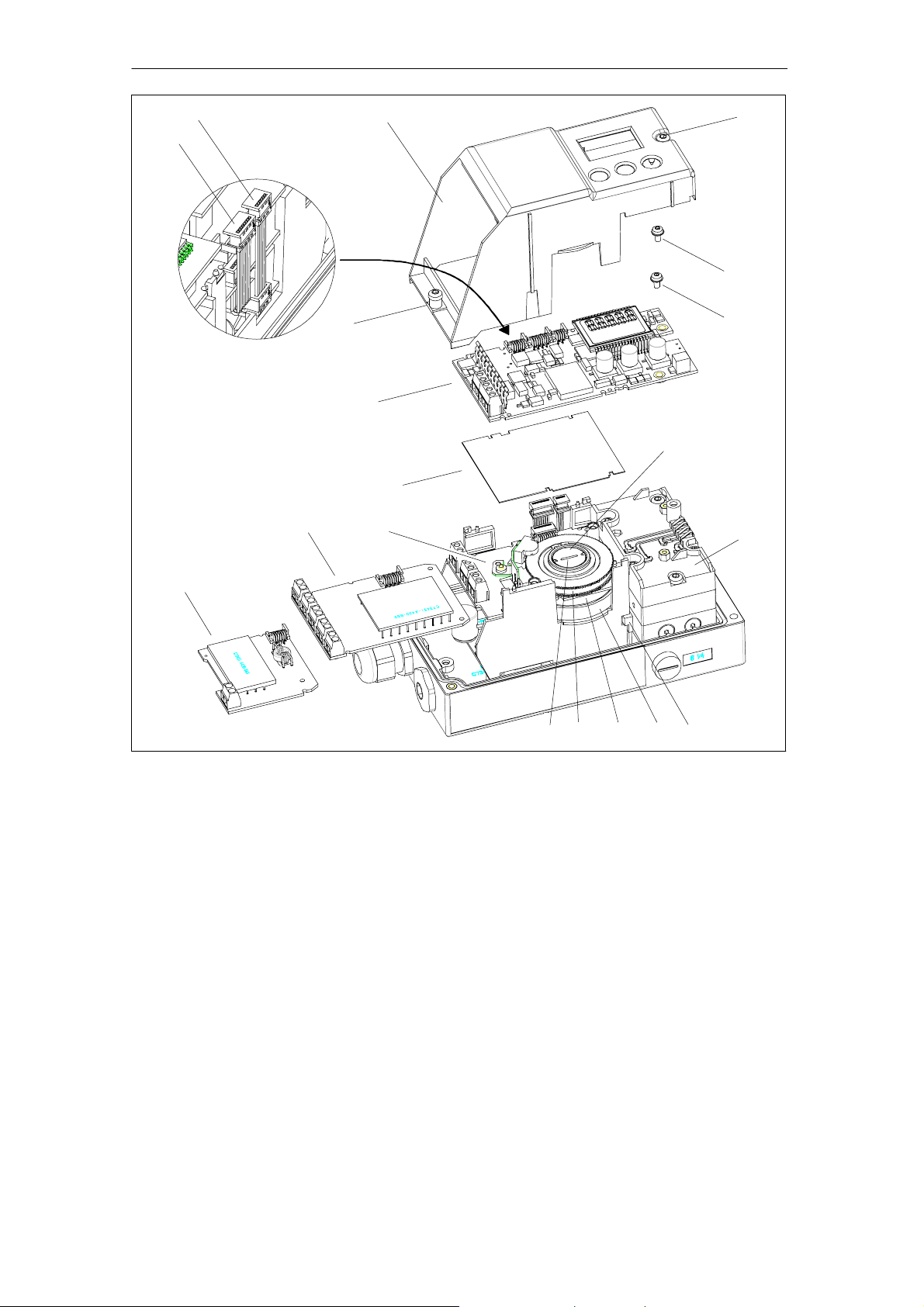
2.7.2 Installation of options modules in explosion proof version
The following option modules are available for the positioner in the explosion-proof version:
-module
--
Iy
-- Alarm module
Installation
.
The options modules are protected and mechanically fixed by a module
cover ((1), see figure 2-12, page 31).
NOTE
The housing must be opened to install the options modules. The
degree of protection IP66/NEMA4x is not guaranteed as long as the
positioner is open.
WARNING
!
In areas in which the atmosphere may be potentially explosive, the
explosion-proof positioner may only be supplied with electrical auxiliary
power when the housing is closed and when built-in, approved electronics are used.
The feed-though openings for the electronic connections must be
sealed with EEX-d certified cable glands or EEx-d certified plugs or
an ignition lock must be mounted at a maximum distance of 46 cm
(18 inches) when using the “conduit”-system.
Open the
positioner
SIPART PS2 Manual
A5E00074631- -06
See figure 2-12, page 31. Disconnect or isolate the power supply
cables first.
To open the positioner, the safety catch (12) must be opened and the
screw-on cover unscrewed.
After loosening the four fixing screws (13.1) the complete rack (13) can
be removed. The actuator may have to be turned so that the clutch can
be easily disengaged.
Remove the module cover (1). To do this, the two screws (1.1) must be
removed with a screwdriver.
29
Page 30

Design and Functional Principle
.
NOTE
To prevent premature wearing of the fixture by the self-tapping screw
(1.1) next to the display, the following method of mounting the module
cover (1) has proven effective.
1. Turn the screws counterclockwise until you feel them snap into the
thread.
2. Tighten both screws carefully in clockwise direction.
30
SIPART PS2 Manual
A5E00074631- -06
Page 31

1.1
Design and Functional Principle
10
13.1
12
8
7
13.1
56
13
1
1.1
2
4
3
11
1 Module cover 7 Transmission ratio selector
1.1 Fixing screws 8 Adjusting wheel for friction clutch
2 PA module 10 Housing
3I
module with ribbon cable 11 Screw-on cover
y
4 Alarm module with ribbon cable 12 Safety catch
5 Ribbon cable for alarm module 13 Rack
6 Ribbon cable for I
module 13.1 Fixing screws
y
Figure 2-12 Installation of the options modules in the explosion proof version
2.7.3 Iy-module
Function
SIPART PS2 Manual
A5E00074631- -06
With the Iyoption module, the current actuator position can be output
as a two wire signal I
= 4 to 20 mA – potentially isolated from the
y
standard controller. The dynamic control of the I
error self-reporting.
module makes it also
y
31
Page 32

Design and Functional Principle
Installation
2.7.4 Alarm module
Function
Insert the Iymodule (3) in the lower slot of the rack up to the stop and
use the 6-pin flat ribbon cable (6) provided to connect it to the
motherboard (see figure 2-11, page 28).
The alarm module contains
S 3 digital outputs and
S 1 digital input
The digital outputs serve to output fault messages and alarms. The
configuration is described in chapter 4.4, page 95, with the parameters 44 to 54.
By an external signal applied at digital input (DI2) the actuator can be
blocked or driven to its limit positions for example depending on the
configuration. The configuration is described in chapter 4.4, page 95,
with the parameters 43.
The alarm module is available in two versions:
S explosion protected for connecting to switching amplifier
EN 60947-5-6
Installation
S non-explosion protected for connection to voltage sources with a
maximum 35 V
The semiconductor outputs of the alarm module report an alarm (signal
state Low) by switching off with high resistance. They are conductive in
the High state (without alarm). The dynamic control makes them error
self-reporting.
The outputs are potentially isolated from the basic circuit and each
other.
The digital input is double.
S one potential isolated for voltage level
S one not potential isolated for floating contacts
These two inputs are designed as logic OR links.
Insert the alarm unit (4) below the motherboard in the rack up to the
stop and use the 8-pin flat ribbon cable (5) to connect it to the motherboard (see figure 2-1 1, page 28).
32
SIPART PS2 Manual
A5E00074631- -06
Page 33

2.7.5 SIA module
Design and Functional Principle
The SIA module contains:
S one binary output
S two binary outputs
Function
Installation
A collected fault message (see alarme module) is output via the binary
output. The floating digital output is implemented as a self error reporting semiconductor output.
The two binary outputs are used to report two mechanically adjustable
limit values (L1, L2) via slot initiators. These two outputs are electrically
independent of the rest of the electronics.
(Slot Initiator Alarm module) Proceed as follows for installation
(figure 2-11, page 28)::
1. Remove all the electrical connections from the motherboard (2).
2. Loosen the two fixing screws (2.1) of the motherboard.
3. Snap out the motherboard by carefully bending the four holders.
4. Insert the SIA module (7) from above until it reaches the upper
circuit board rail of the rack.
5. Push the SIA module into the circuit board rail of the rack approx.
3 mm towards the right.
6. Screw the special screw (7.1) through the SIA module into the axle
of the positioner (Torque: 2 Nm):
CAUTION
The pin pressed into the actuating disc bearing (12) must be adjusted
to just before touching with the special screw. The actuating disc bearing and the special screw must then be turned simultaneously so that
the pins slot into the special screw.
7. Place the insulating cover (10) over the SIA module underneath
the surface of the motherboard at the container wall on one side.
The recesses in the insulating cover must slot into the corresponding lugs on the container wall. Place the insulating cover on the
SIA module by carefully bending the container walls.
8. Snap the motherboard into the four holders and screw it tight again
with the two fixing screws (2.1).
SIPART PS2 Manual
A5E00074631- -06
33
Page 34

Design and Functional Principle
9. Make all the electrical connections between the motherboard and
the options with the ribbon cables provided and between the motherboard and potentiometers with the potentiometer cable.
10. Fix the enclosed module cover instead of the standard version with
the two screws (1.1).
1 1. Select the plates which already exist on the standard version of the
module cover from the set of plates enclosed. Stick the selected
plates according to the standard version to the mounted module
cover. In the case of the version which doesn’t feature explosion
protection, stick the warning sign onto the side of the ground plate
opposite the name plate.
12. Make the electrical connections.
Setting the two limit values:
.
.
NOTE
Connect a suitable display instrument such as the Initiator-Tester
type 2/Ex made by Peperl+Fuchs to the terminals 41 and 42 or terminals 51 and 52 of the SIA module to be able to see the switching state
of the slot initiators.
1. Drive the actuator to the first desired mechanical position.
2. Adjust the top actuating disc (7.2) by hand until the output signal
on terminals 41 and 42 changes.
3. Drive the actuator to the second desired mechanical position.
4. Adjust the bottom actuating disc (7.3) by hand until the output signal on terminals 51 and 52 changes.
NOTE
If you turn the actuating disc beyond the switching point up to the next
switching point, you can set a high-low or a low-high change.
To avoid the actuating discs being accidentally adjusted during operating, they are relatively sluggish. The following remedy might be of help
if you are having trouble with the adjustment: open and close the actuator several times while holding the actuating discs. This temporarily
reduces the friction. This allows an easier and finer adjustment.
34
SIPART PS2 Manual
A5E00074631- -06
Page 35

2.7.6 Mechanical limit switch module
The mechanical limit switch module contains the following:
S A binary output for the output of a group error message)
S Two switches for signaling two limit values that can be set mechani-
cally. These two switches are electrically independent from the rest
of the electronic system.
Design and Functional Principle
Installation
The installation has to be carried as follows (figure 2-11, page 28):
WARNING
!
!
When the mechanical limit switch module is run with AC > 16 V or
DC > 35 V (low voltage), the housing must be protected against
mechanical actions of > 1 Joule, since otherwise the proper functioning
of the IP66 protective system is not guaranteed.
DANGER
When the module is supplied with low voltage, you must observe the
basic safety rules before beginning work on the device, such as:
1. Deenergizing the module by disconnecting it via the disconnecting
device located directly upstream from the module
2. Securing it against being turned on again
3. Ensuring that the module is disconnected from the voltage supply
CAUTION
The following maximal values only refer to the clamps 41 and 42 as
well as the clamps 51 and 52.
SIPART PS2 Manual
A5E00074631- -06
Maximal voltage (not Ex) AC 250 V or DC 24 V
Maximal current (not Ex) AC/DC 4 A
Maximal voltage (Ex) DC 30 V
Maximal current (Ex) DC 100 mA
When you supply one circuit breaker with extra-low voltage (AC <16 V
or DC 35 < V) and the other with low voltage, you ensure that the cable insulation is doubled.
When operating the switch with low voltage, you must position the low
voltage circuits so that they are separated from the extra-low voltage
circuits.
35
Page 36

Design and Functional Principle
Follow the instructions below for installation:
1. Remove all electrical connections on the motherboard (2).
2. Loosen carefully both fixing screws (2.1) for the motherboard.
3. Insert the limit switch module (7) from above until it reaches the
upper printed circuit board rail of the container.
4. Insert the mechanical limit switch module (7) from above until it
reaches the upper circuit board rail of the rack.
5. Push the mechanical limit switch module (7) into the circuit board
rail of the rack approx. 3 mm towards the right.
6. Screw the special screw (7.1) through the mechanical limit switch
module into the axle of the positioner (torque: 2 Nm).
CAUTION
The pin pressed into the actuating disc bearing (12) must be adjusted just before it touches the special screw. In order that the pin
slot into the special screw, you must then turn the actuating disc
bearing and the special screw simultaneously
.
7. Place the insulating cover (10) over the mechanical limit switch
module underneath the surface of the motherboard onto the container on the wall. The recesses in the insulating cover must slot
into the corresponding lugs on the container wall. Place the insulating cover on the mechanical limit switch module by carefully bending the container walls.
8. Snap the motherboard board into the four holders and screw it tight
again with the two fixing screws (2.1).
9. Make sure all electrical connections between the motherboard and
the options using the ribbon cables provided and between the motherboard and potentiometer using the potentiometer cable.
10. Fix the enclosed module cover (1) instead of the standard version
using the two screws (1.1).
NOTE
To prevent premature wearing of the fixture by the self-tapping screws
(1.1), the following method of mounting the module cover (1) has proven effective:
S Turn the screws counterclockwise until you feel them snap into the
thread.
S Tighten both screws carefully in a clockwise direction.
36
SIPART PS2 Manual
A5E00074631- -06
Page 37

Design and Functional Principle
.
NOTE
Before connecting up the limit contact module, ensure that:
S only qualified personnel connect and set the limit contact module.
S all cables are de-energized.
S the cables are stripped so that the insulation is flush with the termi-
nal when plugging in the wires.
S the ends of stranded wires have sleeves.
S the connection cables are insulated according to the permitted cur-
rent load.
S the permissible working temperature of the cables exceeds the
maximal ambient temperature by >25 _C.
S the Ex-version is only allowed to be operated in intrinsically safe
circuits with approved switching amplifiers.
Connection
1. Loosen the screw (1) on the cover (2).
2. Push the cover (2) till it reaches the front stop.
3. Screw each cable tight in the appropriate terminal.
4. Push the cover (2) till it stops at the motherboard.
5. T ighten the screw (1) of the cover (2).
6. Fix the cables of each switch in pairs on the mounting eye using
Figure 2-13 Cable connection
the cable binders provided (3).
SIPART PS2 Manual
A5E00074631- -06
37
Page 38

Design and Functional Principle
Setting the two limit values:
1. Drive the actuator to the first desired mechanical position.
2. Adjust the top actuating disc (7.2) by hand until the output signal
on terminals 41 and 42 changes.
3. Drive the actuator to the second desired mechanical position.
4. Adjust the bottom actuating disc (7.3) by hand until the output signal on terminals 51 and 52 changes.
.
NOTE
To avoid the actuating discs (7.2/7.3) being accidentally adjusted during operation, they are relatively sluggish. The following remedy might
be of help if you are having trouble with the adjustment: open and
close the actuator several times while holding the actuating discs. This
temporarily reduces the friction. This allows an easier and finer adjustment.
2.7.7 EMC filter module
The positioner can also be driven by an external position sensor (potentiometer or NCS) (see page 46 “3.3.2 Instructions for using positioners which are exposed to strong accelerations or vibrations”). An EMC
filter module, order number C73451-A430-D23, is required for this.
38
SIPART PS2 Manual
A5E00074631- -06
Page 39

2.7.8 Accessories
Design and Functional Principle
Y1
Y1
PZ
Figure 2-14 Manometer block (left for single-acting, right for double-acting actuators)
Manometer block
The manometer block for single-acting actuator contains two manometers which are screwed to the lateral pneumatic connection of the
positioner with O-rings. The values for the input pressure (supply air
PZ) and output pressure (actuating pressure Y1) are displayed.
The manometer block for double-acting actuators contains three
manometers which are screwed to the lateral pneumatic connection of
the positioner with O-rings. The values for the input pressure (supply
air PZ) and output pressure (actuating pressure Y1 and Y2) are
displayed.
PZ
Y2
SIPART PS2 Manual
A5E00074631- -06
39
Page 40

Design and Functional Principle
Table 2-1 Scopetuator”
40
SIPART PS2 Manual
A5E00074631- -06
Page 41

Preparing for Operation
Preparing for Operation
This chapter describes all the preparations necessary for operating the
positioner.
3.1 Instrument identification (type key)
The order number of the positioner is printed on the rating plate and on
the packaging. Compare this with the order number in chapter 7.1,
page 154.
Installation of any modules required is described in chapter 2.7,
page 27 of this technical manual.
3.2 Dimensional drawings
3
60
50x4xM6
h9
7
9 deep
1
3729
48
M20 x 1.5 or NPT-adapter
15
14,5
95
2
Y1
65
80
13,5
96,6
23
88,5
E
58
33
M8, 9 deep
182
8
7
38,5
Y1
PZ
Y2
All air connections
G 1/4 or 1/4” NPT
29,5
72
29,5
11, 2
Figure 3-1 Dimensional drawing version plastic housing 6DR5xx0
SIPART PS2 Manual
A5E00074631- -06
41
Page 42

Preparing for Operation
14
25
12
10
5
3x
G1/4or
1/4” NPT
9.5
90
79.5
2xM6
29.5
58.75
82
Thread depth 5.5
50
3.5
5.3
20.5
M4
9.5
9
5
Figure 3-2 Dimensional drawing terminal strip for plastic housing
50x4xM6
9 deep
2
Y1
65
E
M8, 9 deep
23
58
182
13.5
96.5
88.5
8
7
38.5
7
34.5
M20 x 1.5 or NPT-adapter
h9
1
14.5
84
29
27.5
All air connections
G 1/4 or 1/4” NPT
15
12
6.5
Y1
29.5
29,5
11. 2
59
14
PZ
Figure 3-3 Dimensional drawing version metal housing 6DR5xx1
42
SIPART PS2 Manual
A5E00074631- -06
Page 43

Preparing for Operation
M8, 14 deep (4x)
43
65
M6, 11 deep (4x)
129.5
23
7.75
50
60
∅
3.5
All air connections
1/
or1/4”NPT
G
4
25
34
4.5
M6, 8 deep (2x)
M20, M25 or
1/
”NPT (2x)
2
10.25
19,25
1)
7.5
25.7
1)
Connection 238/Y2 only
E
12
87.2
14,3
33.5
7
33.5
in double action version
158.5
82,5
∅ 136.5
235,3
∅ 8h9
Figure 3-4 Dimensional drawing for positioner with metal housing in explosion proof
version 6DR5xx5
3.3 Assembly
General
WARNING
!
To avoid injury or mechanical damage to the positioner/mounting kit,
the following order must be observed for assembly:
1. Mechanical fitting of positioner this chapter
2. Connection of electric power supply see chapter 3.4, p. 57
3. Connection of pneumatic power supply see chapter 3.5, p. 71
4. Put into operation see chapter 3.6, p. 72
Please also observe the warning on page 58!
SIPART PS2 Manual
A5E00074631- -06
43
Page 44

Preparing for Operation
.
!
NOTE
The positioner will be equipped at the factory and delivered complete
with the necessary options at the customer’s request. Options modules
may only be retrofitted by our service technicians.
The positioner must be assembled – especially in a moist environment
– in such a way as to rule out freezing of the positioner axle at low
ambient temperature.
The operating keys must be covered to prevent liquid getting in.
WARNING
In the combination of components it must be ensured that only
positioners and options modules are combined which are approved
for the respective area of application. This applies especially for safe
operation of the positioner in areas in which the atmosphere is potentially explosive (zone 1 and 2). The instrument categories (2 and 3) of
the instrument itself and those of its options must be observed.
In addition, you must always make sure that no water gets into an open
housing or screw-type gland. This may be the case for example when
the positioner cannot be finally assembled and connected immediately.
It generally applies that the positioner may only be operated with dry
compressed air. Therefore use the normal water traps. An additional
drying unit may even be necessary in extreme cases. This is particularly important when operating the positioner at low ambient temperatures. Please set the purge air switch (on the valve block above the
pneumatic terminals) additionally to the “OUT” position.
Use a sufficiently rugged console (e.g. plate thickness > 4 mm with
reinforcements) for part-turn actuators and the mounting kit “linear
actuator” or integrated connection for linear actuators.
3.3.1 Instructions for using positioners in a wet environment
This information gives you important instructions for the assembly and
operation of the positioner in a wet environment (frequent, heavy rain
and/or prolonged tropical condensation) in which the IP66 degree of
protection is no longer sufficient and especially when there is a danger
that water may freeze.
To prevent water getting into the instrument in normal operation (e.g.
through the exhaust air openings) or the display being poorly legible,
please avoid the unfavorable installation positions illustrated in
figure 3-5.
44
SIPART PS2 Manual
A5E00074631- -06
Page 45

Figure 3-5 Favorable and unfavorable installation positions
If conditions oblige you to operate the positioner in a unfavorable
installation position, you can take additional precautionary measures to
prevent penetration by water.
Preparing for Operation
Procedure
.
NOTE
Never clean the positioner with a high pressure water jet because the
IP66 degree of protection is inadequate protection for this.
The necessary additional measures to prevent penetration by water
depend on the installation position chosen and you may additionally
require:
S screw-type gland with sealing ring (e.g. FESTO: CK –1 / 4–PK–6)
S plastic hose approx. 20 to 30 cm (e.g. FESTO PUN- 8X1,25 SW)
S cable straps (number and length depends on local conditions)
S Connect the pipes in such a way that rain water which runs along
the pipes can drip off before it reaches the terminal strip of the positioner.
S Check the electrical connections for perfect firm contact.
S Check the seal in the housing cover for damage and contamination.
Clean and replace if necessary .
S Mount the positioner if possible so that the sinter bronze silencer
faces downwards on the underside of the housing (vertical installation position). If this is not possible, the silencer should be replaced
by a suitable screw-type gland with a plastic hose.
SIPART PS2 Manual
A5E00074631- -06
45
Page 46

Preparing for Operation
Assembly of the screw-type gland with plastic hose
S Unscrew the sinter bronze silencer from the exhaust air opening on
the underside of the housing.
S Screw the screw-type gland mentioned above into the exhaust air
opening.
S Mount the above mentioned plastic hose on the screw-type gland
and check the good fit.
S Fix the plastic hose with a cable strap to the fitting so that the open-
ing faces downwards.
S Make sure that the hose has no kinks and the exhaust air can flow
out unhindered.
3.3.2 Instructions for using positioners which are exposed to strong accelerations or vibrations
NOTICE
for explosion-proof versions:
Only adjust the outer friction clutch (8, Fig. 2-12, page 31). The internal
friction clutch (8, Fig. 2-1 1, page 28) is fixed and, for the explosionproof version, must not be adjusted.
The electro-pneumatic positioner SIPART PS2 has a friction clutch and
switchable gearing and can thus be used universally for part-turn and
linear actuators. This means that, for part-turn actuators you don’t have
to worry about the zero point and for linear actuators, you don’t have to
worry about symmetrical mounting, as you can adjust the working
range after installation, with the help of the friction clutch.
The switchable gearing allows you to also adjust the positioner for
small or large lifts.
Occasionally it can happen, that in the rough environment of process
systems (e.g. due to incorrectly fitted valves or if “steam pulses” occur)
that the shaft to monitor the position of the SIPART PS2 positioner is
exposed to extreme acceleration, which far exceeds its specified load
limits, and which could result in an unwanted shift in the friction clutch
or in the gears in the position monitoring jumping briefly out.
For cases like this, as standard, the SIPART PS2 positioner is fitted
with a locking device for the friction clutch and you can also lock the
setting of the transmission ratio selector. This means that an unwanted
change to the position monitoring due to the above mentioned effects
can be reliably prevented.
46
Both of these locking options are labeled via additional tags inside the
device (see Figure 3-6, page 47). Note that these locks are only required if extreme acceleration or strong vibration might be present
within your process.
SIPART PS2 Manual
A5E00074631- -06
Page 47

Preparing for Operation
Procedure After you have installed the positioner and put it fully into operation, you
can set the torque for the friction clutch as follows:
S On the module cover, insert an ordinary 4 mm wide screwdriver into
a slot on the yellow wheel.
S Now use the screwdriver to move the yellow wheel to the left, until
you can feel that it clicks in. This increases the torque of the friction
clutch.
S You can recognize a locked friction clutch by an approx. 1 mm wide
gap between the yellow and black wheels.
S If you have to set the zero pint e.g. after exchanging the actuator,
first reduce the torque by turning the yellow wheel to the right until
you hit the stop. After setting the zero point, you can refix the friction
clutch as described above.
Starting from the neutral setting (as delivered), you can lock the transmission ratio selector as follows:
S Adjust the yellow wheel underneath the terminals with an ordinary
4 mm wide screwdriver to correspond to the setting that you would
like (33_ or 90_), turning to the left or right, until you can feel that it
clicks in.
S Please note that you can only adjust the transmission ratio selector
after releasing the fixing.
For this reason you first have to put the yellow ring into the neutral
position, if you have to adjust the transmission ratio selector
e.g. after exchanging the actuator).
90_
(1)
(1) Transmission ratio selector interlock
(2) Open
(3) Friction clutch
(4) Close
90
(2)
(3)
33
33_
(4)
Figure 3-6 Locking and fixing mechanisms
SIPART PS2 Manual
A5E00074631- -06
47
Page 48

Preparing for Operation
External position
displacement
sensor
Applications in which the measures described above are inadequate
are also conceivable. This applies for instance with continuous and
heavy vibration, increased or too low ambient temperatures and in the
case of nuclear radiation.
The separate attachment of position displacement sensor and
controller unit can help here. A universal component is available which
is suitable both for linear and part-turn actuators.
You require the following:
S The external position detection system (order no.
C73451-A430-D78). This consists of a SIP ART-PS2-housing with
integrated friction clutch, built-in potentiometer and various dummy
plugs and seals.
S or a Non-Contacting Position Sensor (e.g. 6DR4004-6N).
S The controller unit, any positioner version.
S The EMC filter module, this is is a set together with cable clips
and M-20 screw-type cable gland and has the order number
C73451-A430-D23. The EMC filter module must be installed in the
positioner. The installation instructions enclosed with the EMC filter
module explain how to assemble the components.
S A 3-wire cable for connecting the components.
This EMC filter module should always be used for the controller unit
when any actuator-mounted potentiometer (resistance 10 kΩ)isto
be used instead of the position detection system C73451-A430-D78.
WARNING
!
The explosion-proof version may not be run together with the external
position detection system.
48
SIPART PS2 Manual
A5E00074631- -06
Page 49

Preparing for Operation
3.3.3 Mounting kit “linear actuator” 6DR4004-8V and 6DR4004-8L
The scope of delivery of the mounting kit “linear actuator IEC 534
(3 mm to 35 mm)” are contained (ser. no. see figure 3-7, page 51):
Ser. no. pieces Designation Note
1 1 NAMUR mounting kit bracket
IEC 534
2 1 Pick-up bracket Guides the roller with carrier pin and turns lever
3 2 Clamping assembly Mounting of pick-up bracket on actuator spindle
4 1 Carrier pin Assembly with roll (5) on lever (6)
5 1 Roll Assembly with driver pin (4) on lever (6)
6 1 Lever NAMUR Forstrokerange3mmto35mm
7 2 U bolt Only for actuators with columns
8 4 Hexagon head screw M8 x 20 DIN 933-A2
9 2 Hexagon head screw M8 x 16 DIN 933-A2
10 6 Lock washer A8 -- DIN 127-A2
11 6 Flat washer B 8,4 -- DIN 125-A2
12 2 Flat washer B 6,4 -- DIN 125-A2
13 1 Spring VD--115E 0.70 x 11.3 x 32.7 x 3.5
14 1 Spring washer A6 -- DIN 137A-A2
15 1 Lock washer 3.2 -- DIN 6799-A2
16 3 Spring washer A6 -- DIN 127-A2
17 3 Socket cap screw M6 x 25 DIN 7984-A2
18 1 Hexagon nut M6 -- DIN 934-A4
19 1 Square nut M6 -- DIN 557-A4
21 4 Hexagon nut M8 -- DIN 934-A4
Standardized connection for mounting console with
ledge, column or plane surface
arm
For stroke ranges> 35 mm to 130 mm (special delivery), lever 6DR4004-8L is required additionally
Table 3-1 Scope of delivery of the mounting kit “linear actuator”
SIPART PS2 Manual
A5E00074631- -06
49
Page 50

Preparing for Operation
3.3.4 Assembly procedure (see figure 3-7, page 51)
1. Mount clamping assembly (3) with hexagon socket cap screws
(17) and lock washer (16) on the actuator spindle.
2. Insert the pick-up bracket (2) into the recesses of the clamping
assembly. Set the necessary length and tighten the screws so that
the pick-up bracket can still be shifted.
3. Insert the pin (4) in the lever (6) and assemble with nut (18), spring
washer (14) and washer (12).
4. The value of the stroke range specified on the actuator or if this
does not exist as a scaling value, the next greatest scaling value is
set. The center of the pin must be in line with the scaling value.
The same value can be set later under parameter 3.YWAY in
commissioning to display the way in mm after initialization.
5. Assemble the hexagon socket cap screw (17), spring washer (16),
washer (12) and square nut (19) on the lever.
6. Push the premounted lever onto the positioner axis up to the stop
and fix with the hexagon socket cap screw (17).
7. Fit the mounting bracket (1) with two hexagon head screws (9),
lock washer (10) and flat washer (11) on the rear of the positioner.
.
8. Selection of the row of holes depends on the width of the actuator
yoke. The pin (4) should engage in the pick-up bracket (2) as close
as possible to the spindle but may not touch the clamping
assembly.
9. Hold the positioner with the mounting bracket on the actuator so
that the pin (4) is guided within the pick-up bracket (2).
10. Tighten the pick-up bracket.
1 1. Position the mounting parts according to the type of actuator.
-- Actuator with ledge: Hexagon head screw (8), flat washer (11)
and lock washer (10).
-- Actuator with plane surface: Four hexagon head screws (8), flat
washer (11) and lock washer (10).
-- Actuator with columns: Two U bolts (7), four hexagon nuts (21)
with flat washer (11) and lock washer (10).
12. Secure positioner onto the yoke using the previously positioned
mounting parts.
NOTE
Set the height of the positioner so that the horizontal lever position is
reached as close to the stroke center as possible. You can use the
lever scale as orientation. It must be guaranteed that the horizontal
lever position is passed through within the stroke range.
50
SIPART PS2 Manual
A5E00074631- -06
Page 51

Preparing for Operation
2
16
17
1)
3
Without explosion-proof version:
11
10
9
1
17
16
12
19
18
14
12
6
4
11
10
3)
9
Explosion-proof version:
11
10
9
1
11
10
3)
Figure 3-7 Assembly procedure (linear actuator)
9
SIPART PS2 Manual
A5E00074631- -06
51
Page 52

Preparing for Operation
1
10
8
Mounting on yoke
11
with ledge
4)
11
Mounting on yoke
with plane surface
11
Mounting on yoke
with columns
10
8
10
7
21
as required
Figure 3-7 Assembly procedure (linear actuator) continued
3.3.5 Mounting kit “part-turn actuator” 6DR4004-8D
The scope of delivery of the mounting kit “part-turn actuator” contains (ser. no. see figures 3-8
and 3-9):
Ser. no. Pieces Designation Note
2 1 Coupling wheel Mounting on position feedback shaft of the
SIPART PS2
3 1 Carrier Mounting on end of actuator shaft
4 1 Multiple plate Indication of actuator position, comprising 4.1
and 4.2
4.1 8 Scales Different divisions
4.2 1 Pointer mark Reference point for scale
14 4 Hexagon head screw DIN 933 -- M6 x 12
15 4 Lock washer S6
16 1 Fillister head screw DIN84--M6x12
17 1 Washer DIN125–6.4
18 1 Hexagon socket head screw Premounted with coupling wheel
19 1 Allen key For item 18
Table 3-2 Scope of delivery of the mounting kit “part-turn actuator”
52
SIPART PS2 Manual
A5E00074631- -06
Page 53

3.3.6 Assembly procedure (see figure 3-8 and figure 3-9)
1. Attach VDI/VDE 3845 mounting console ((9), actuator-specific,
scope of delivery actuator manufacturer) onto rear of positioner
and secure using hexagon head screws (14) and lock washers
(15).
2. Adhere pointer (4.2) onto mounting console in the center of the
centering hole.
3. Push the coupling wheel (2) onto positioner axis, pull back by
about 1 mm and tighten the hexagon socket head screw (18) with
the Allen key provided.
4. Place the carrier (3) onto the end of the actuator and secure using
Fillister head screw (16) and washer (17).
5. Carefully place positioner with mounting console onto the actuator
such that the pin of the coupling wheel engages in the actuator.
6. Align the positioner/mounting console assembly in the center of the
actuator and screw tight.
(Screws not included in delivery; they are part of the actuator
mounting console!)
Preparing for Operation
7. Following startup as described in Chapter 3.6, page 72: Drive the
actuator to the end position and adhere scale (4.1) on the coupling
wheel (2) according to direction of rotation and part-turn actuator.
The scale is self--adhesive!
SIPART PS2 Manual
A5E00074631- -06
53
Page 54

Preparing for Operation
9
1)
3
15
14
2
18
2)
16
17
3)
2
3
4)
Figure 3-8 Assembly procedure (part-turn actuator)
2
4.1
0%20 40 60 80 100%
5)
54
SIPART PS2 Manual
A5E00074631- -06
Page 55

Preparing for Operation
15
14
9
1)
16
17
3
2)
18
2
3)
2
4.1
2
0%20 40 60 80 100%
3
4)
5)
Figure 3-9 Assembly procedure for explosion proof version (part-turn actuator)
SIPART PS2 Manual
A5E00074631- -06
55
Page 56

Preparing for Operation
15
14, 15
2
25
A
CUT A -- B
4.2 14, 15
positioner
G1/4
B
part-turn actuator
3 16, 17 10 4.1 9
2 Coupling wheel 10 Feedback shaft
3 Carrier 14 Hexagon head screw M6 x 12
4 Multiple plate 15 Lock washer S6
4.1 Scale 16 Fillister head screw M6 x 12
4.2 Pointer mark 17 Washer
9 VDI/VDE 3845-mounting bracket 18 Hexagon socket head screw
Figure 3-10 Mounted positioner for part-turn actuator
56
SIPART PS2 Manual
A5E00074631- -06
Page 57

Befestigungsebene
fastening level
Stellungsregler
positioner
Preparing for Operation
M6
Schwenkantrieb
part-turn actuator
F05-Lkr.- 50
Figure 3-11 Attachment of part-turn actuator, mounting console (scope of delivery actuator manufacturer),
dimensions
+0,1
4
35
3.4 Electrical Connection
.
!
NOTE
Any necessary options modules must be installed before electrical
connection (see chapter 2.7, page 27).
N.B.: The transmission ratio selector can only be set when the
positioner is open. Therefore check this setting before closing the
controller.
WARNING
The specifications of the examination certificate valid in your country
must be observed.
Electrical connection in hazardous areas
The national directives and laws which apply in your country for hazardous areas, must be followed for electrical installations. In Germany
these are, for example:
-- Working reliability regulations
-- Regulations for installing electrical equipment in hazardous areas,
DIN EN 60079-14 (in the past VDE 0165, T1).
-- The EC type examination certificates
SIPART PS2 Manual
A5E00074631- -06
57
Page 58

Preparing for Operation
!
WARNING
If the intrinsically safe version is operated with a higher operating voltage by mistake, the positioner must no longer be used for intrinsically
safe application.
The explosion-proof positioner may only be supplied with electrical
power in areas in which the atmosphere may be potentially explosive
when the housing is closed. Where power supply is required, we
recommend checking the power supply to ensure that it corresponds
with that on the name plate and with the test certification valid for your
country.
The feed-though openings in the explosion-proof version for the
electronic connections must be sealed with EEX-d certified cable
glands or EEx-d certified plugs or an ignition lock must be mounted at
a maximum distance of 46 cm (18 inches) when using the “conduit”system.
The plastic housing is metal lined to increase the electromagnetic
compatibility (EMC) against high frequency radiation. This screen is
connected electrically to the threaded bushes shown in figure 3-12,
page 58.
Please bear in mind that this protection can only be effective if you connect at least one of these bushes with grounded fittings by electrically
conductive (blank) mounting parts.
Figure 3-12 Base plate
58
Shield
SIPART PS2 Manual
A5E00074631- -06
Page 59

Preparing for Operation
.
NOTE
Use standard M20 x 1.5 cable gland nuts to ensure leakage (IP-protection of the housing) and for the necessary tensile strength use only
cables with a cable diameter ≥ 8 mm, or for smaller diameters use a
suitable sealing insert.
For the NPT version, the positioner will be delivered with an adapter.
Make sure that when fitting a part into the adapter, that the maximum
permissible torque of 10 Nm is not exceeded.
NOTE for use in zone 2:
Non-sparking equipment for Zone 2 may not be connected or disconnected under power in normal operation.
However, during installation or repair work the positioner may be connected or disconnected even under power (see also certificate for
zone 2).
NOTE for use in two-wire systems:
Never connect the current input (terminal 6 and 7) to a voltage source
as this could destroy the positioner.
Always use a current source with a maximum output current of 20 mA.
To maintain the power supply, the input current must be ≥3.6 mA.
3.4.1 Connection in non-intrinsically safe and explosion proof version
+
4to20mA
J
Figure 3-13 Two-wire connection
6
7
8
9
10
HART Communicator
E
Positioner
A
Digital input 1
Only for:
6DR51x0-xNxxx
6DR5111-x Nxxx
6DR51x5-xExxx
6DR50x0-xNxxx
6DR5011-xNxxx
6DR51x0-xNxxx
6DR5111-x Nxxx
6DR50x5-xExxx
6DR51x5-xExxx
SIPART PS2 Manual
A5E00074631- -06
59
Page 60

Preparing for Operation
+
J
Figure 3-14 Two-wire connection
+
U
4to20mA
18 to 30 V
2
3
4
5
6
7
8
9
10
HART Communicator
2
3
4
5
Positioner
E
A
Digital input 1
Only for:
6DR52x5-xExxx
Positioner
6DR53x0-xNxxx
6DR52x5-xExxx
6DR53x5-xExxx
6DR53x0-Nxxx
6DR52x5-Exxx
6DR53x5-Exxx
+
*)
J
Figure 3-15 Three-/four-wire connection
0/4to20mA
6
*)
7
8
9
10
HART Communicator
E
A
Digital input 1
Only for:
6DR52x5-xExxx
*) only for three-wire connection
60
SIPART PS2 Manual
A5E00074631- -06
Page 61

Current output
Preparing for Operation
+
≤35 V
U
H
+
Figure 3-16 I
module 6DR4004-8J, not Ex
y-
Digital inputs and outputs
+13 V
+
≤30 V
+4,5 V
+
35 V
616261
62
Alarm module
6DR4004-8A
11
12
+3 V
21
22
1K
31
32
E
J
module:
Iy
6DR4004-8J
≥1
Fault
message
Digital input 2
+
35 V
41
42
+
35 V
51
52
Figure 3-17 Alarm module 6DR4004-8A, not Ex
1K
Limit value A1
1K
Limit value A2
SIPART PS2 Manual
A5E00074631- -06
61
Page 62

Preparing for Operation
SIA module
SIA module
6DR4004-8G
+
<35 V
+
8.2 V
+
8.2 V
Switching amplifier according to EN 60947-5-6
Figure 3-18 SIA module 6DR4004-8G, not Ex
31
32
41
42
51
52
Mechnical limit switch module
+
<35 V
=
31
32
1K21
10K
Limit switch module
6DR4004-8K
1K21
10K
Fault
message
Limit value A1
Limit value A2
Fault
message
+
max. AC 250 V
DC 24 V
Figure 3-19 Mechanical limit switch module 6DR4004-8K, not Ex
AC/DC 4 A
+
max. AC 250 V
DC 24 V
AC/DC 4 A
41
42
51
52
3.4.2 Connection in intrinsically safe version
.
NOTE
Only certified intrinsically safe circuits may be connected as power
supply, control and signal circuits.
Limit value A1
Limit value A2
62
SIPART PS2 Manual
A5E00074631- -06
Page 63

Standard controller
Preparing for Operation
Non-hazardous
area
EEx
Intrinsically
safe power
source
Figure 3-20 Two-wire connection, EEx i
Non-hazardous
area
EEx
Intrinsically
safe power
source
+
J
+
J
Hazardous area zone 1 or zone 2
4to20mA
Hazardous area zone 1 or zone 2
4to20mA
6
7
8
9
10
6
7
8
9
10
E
2
3
4
5
Positioner
A
Digital input 1
E
A
Positioner
Digital input 1
6DR5010-xExxx
6DR5020-xExxx
6DR5011-xExxx
6DR5210-xExxx
6DR5220-xExxx
6DR5211-xExxx
Figure 3-21 Two-wire connection, EEx i
SIPART PS2 Manual
A5E00074631- -06
HART Communicator
63
Page 64

Preparing for Operation
Non-hazardous
area
EEx
EEx
Intrinsically
safe power
source
Figure 3-22 Three-/four-wire connection, EEx i
+
U
+
*)
J
Hazardous area zone 1 or zone 2
18 to 30 V
4to20mA
*)
HART Communicator
6
7
8
9
10
2
3
4
5
Positioner
E
A
Digital input 1
*) Only for three-wire connection
6DR5210-xExxx
6DR5220-xExxx
6DR5211-xExxx
64
SIPART PS2 Manual
A5E00074631- -06
Page 65

Split-range
area
Power supply
EEx
Preparing for Operation
Hazardous area zone 1 or zone 2Non-hazardous
L+
M
U
+18to30V
Instrument 1
Positioner
6DR5210-xExxx
6DR5220-xExxx
6DR5211-xExxx
EEx
intrinsically safe feed sources
total setting
I
range Iy
Iy
+0/4 to 20 mA
M
setting range 1
Digital input 1
#
Instrument 2
Positioner
6DR5210-xExxx
6DR5220-xExxx
6DR5211-xExxx
setting range 2
Digital input 1
#
Figure 3-23 Series circuit of two positioners, e.g. split range (separate power supply), EEx i
SIPART PS2 Manual
A5E00074631- -06
65
Page 66

Preparing for Operation
Current output
Non-hazardous area
EEx
U
J
+
U
H
≤30 V
+
Intrinsically safe power source
Figure 3-24 I
-module 6DR4004-6J, EEx i
y
Digital inputs and outputs
Non-hazardous area
Hazardous area zone 1 or zone 2
+
616261
62
E
J
Iymodule
6DR4004-6J
Hazardous area zone 1 or zone 2
Alarm module
6DR4004-6A
+
≤25.2 V
EEx
EEx
+
8.2 V
Intrinsically safe
switching
amplifier to DIN
EN 60947-5-6
+
EEx
8.2 V
+
8.2 V
EEx
Figure 3-25 Alarm module 6DR4004-6A, EEx i
11
12
21
22
31
32
41
42
51
52
10K
10K
10K
2K1
2K1
2K1
≥1
Digital
input 2
+
3V
Fault
message
Limit value A1
Limit value A2
66
SIPART PS2 Manual
A5E00074631- -06
Page 67

SIA module
Preparing for Operation
Non-hazardous area
EEx
EEx
EEx
+
8.2 V
+
8.2 V
+
8.2 V
Intrinsically safe
Switching amplifier to DIN EN
60947-5-6
Figure 3-26 SIA module 6DR4004-6G, EEx i
Mechnical limit switch module
Hazardous area zone 1 or zone 2
SIA module
6DR4004-6G
2K1
31
32
41
42
51
52
10K
Fault
message
Limit value A1
Limit value A2
Non-hazardous area
Intrinsically safe
Switching amplifier to DIN EN
60947-5-6
+
EEx
= I
=
Figure 3-27 Mechnical limit switch module 6DR4004-8K, EEx i
max. DC 8,2 V
+
DC 30 V
U
max
100 mA
max
+
U
DC 30 V
max
100 mA
I
max
Hazardous area zone 1 or zone 2
Mechanical limit switch module
6DR4004-6K
31
10K
32
41
42
51
52
2K1
Fault
message
Limit value A1
Limit value A2
SIPART PS2 Manual
A5E00074631- -06
67
Page 68

Preparing for Operation
3.4.3 Connection in type of protection “n” version
Standard controller
Non-hazardous area
+
J
Figure 3-28 Two-wire connection, EEx n
Non-hazardous area
J
+
4to20mA
Hazardous area zone 2
4to20mA
Hazardous area zone 2
6
7
8
9
10
2
3
4
5
6
7
8
9
10
E
A
Positioner
Digital input 1
Positioner
E
A
6DR5010-xGxxx
6DR5020-xGxxx
6DR5011-xGxxx
6DR5210-xGxxx
6DR5220-xGxxx
6DR5211-xGxxx
Digital input 1
Figure 3-29 Two-wire connection, EEx n
68
HART Communicator
SIPART PS2 Manual
A5E00074631- -06
Page 69

Preparing for Operation
Non-hazardous area
Hazardous area zone 2
+
18 to 30 V
U
+
*)
0/4to20mA
*)
J
HAR Communicator
Figure 3-30 Three-/Four-wire connection, EEx n
6
7
8
9
10
2
Positioner
3
4
6DR5210-Gxxx
6DR5220-Gxxx
6DR5211-Gxxx
5
E
A
Digital input 1
*) Only for three-wire connection
Current output
Non-hazardous area
U
H
≤30 V
Figure 3-31 I
-module 6DR4004-6J, EEx n
y
Hazardous area zone 1 or zone 2
+
+
616261
62
+
E
I
Iymodule
6DR4004-6J
SIPART PS2 Manual
A5E00074631- -06
69
Page 70

Preparing for Operation
Digital inputs and outputs
Non-hazardous area
+
+
+
+
8.2 V
8.2 V
8.2 V
Hazardous area zone 2
Alarm module
6DR4004-6A
11
12
21
+3 V
22
2K1
31
10K
32
2K1
41
10K
42
2K1
51
10K
52
≥1
Fault
message
Limit value A1
Limit value A2
Digital
input 2
Figure 3-32 Alarm module 6DR4004-6A, EEx n
SIA module
Non-hazardous area
+
8.2 V
+
8.2 V
+
8.2 V
Hazardous area zone 2
SIA module
6DR4004-6G
2K1
31
10K
32
41
42
51
52
Fault
message
Limit value A1
Limit value A2
Figure 3-33 SIA module 6DR4004-6G, EEx n
70
SIPART PS2 Manual
A5E00074631- -06
Page 71

3.5 Pneumatic Connection
WARNING
!
For reasons of safety, the pneumatic power may only be supplied after
assembly when the positioner is switched to operating level P manual
operation with electrical signal applied (as-delivered state, see
figure 4-4, page 92).
Preparing for Operation
.
NOTE
Note the air quality! Oil-free industrial air, solid content < 30 μm, pressure
dew point 20 K below the lowest ambient temperature (chapter 7 “Technical Data”, page 153).
S Connect a manometer block for supply air and actuating pressure if
necessary.
S Connection by female thread G 1/4 DIN 45141 or 1/4” NPT:
P
Z
Y1 Actuating pressure 1 for single- and double-acting actuators
Y2 Actuating pressure 2 for double-acting actuators
E Exhaust air outlet (remove silencer if necessary)
see figure 2-4 and 2-5, page 19.
Supply air 1.4 to 7 bar
S Safety position when the electric power supply fails:
single-acting: Y1 deaerated
double-acting: Y1 Max. Actuating pressure
(supply air pressure)
Y2 deaerated
S Connect actuating pressure Y1 or Y2 (only in double-acting actua-
tors) according to the desired safety position.
.
SIPART PS2 Manual
A5E00074631- -06
S Connect supply air to P
NOTE
In order for spring-loaded pneumatic actuators to be able to reliably
exploit the maximum possible travel, the supply pressure must be
sufficiently greater than the maximum required final pressure of the
actuator.
After installing the device, check the pneumatic connections of the entire
assembly for leakage. Any leakage would cause not only continuous
consumption of compressed air but also would cause the positioner to
continually endeavor to compensate for the variance in position, leading
in time to premature wear of the whole control mechanism.
.
Z
71
Page 72

Preparing for Operation
3.6 Commissioning
Once the positioner has been fitted to a pneumatic actuator, it must be
provided with electrical and pneumatic auxiliary power.
Then you can then adapt the position controller to the respective actuator by parameterizing and initializing it.
Mode” operating mode (which can also if necessary be attained by
“PRST”) - - “NOINI” will flash.
If the positioner has not been initialized it will be in the “P Manual
Mode“ operating mode (which can also if necessary be attained by
“PRST”) - - “NOINI“ will flash.
This initialization can be effected in three different ways:
S Automatic initialization
Initialization takes place automatically. Hereby the positioner determines the direction of action, the stem travel and the angle of rotation, the travel times of the actuator one after the other and adapts
the control parameters to the dynamic behavior of the actuator.
S Manual initialization
The stem travel or angle of rotation of the actuator can be set
manually, the other parameters are determined as in automatic initialization. This function is useful in actuators with soft limit stops.
.
S Copying initialization data (positioner exchange)
In the devices with HART function the initialization data of a positioner can be read out and copied to another positioner. This enables a defective device to be changed without having to interrupt
an ongoing process by initialization.
Only a few parameters need to be set in the positioner prior to initialization. The others are defaulted so that they do not normally need to be
adjusted. You will have no problems with commissioning if you observe
the following points.
The possible operating modes and parameters, together with the
adjustment capabilities and their effects are described in chapter 4,
page 89 “Operation“.
NOTE
N.B.: The operating pressure should be at least one bar greater than is
necessary for closing/opening the valve during initialization. However,
the operating pressure may not be higher than the maximum permissible operating pressure of the actuator.
N.B.: The transmission ratio selector can only be set when the
positioner is open. Therefore check this setting before closing the
housing.
72
SIPART PS2 Manual
A5E00074631- -06
Page 73

3.6.1 Preparations for linear actuators
1. Assemble the positioner with the appropriate mounting kit
(see chapter 3.3.3, page 39).
Preparing for Operation
.
NOTE
Particularly important is the position of the transmission ratio selector (8, figure 2-2, page 17) in the positioner:
Stroke Lever Position of the transmission ratio
selector
5to20mm short 33° (i.e. down)
25 to 35 mm short 90° (i.e. up)
40 to 130 mm long 90° (i.e. up)
2. Push the carrier pin (4, figure 3-7 (page 51) 2) onto the lever
(6, figure 3-7, 2) to the scale position corresponding to the rated
stroke or next highest position and screw the carrier pin tight with
the nut (18, figure 3-7, 2).
3. Connect the actuator and the positioner with the pneumatic lines
and supply pneumatic power to the positioner (figure 2-4 and 2-5,
page 19).
4. Connect a suitable current or voltage source (see figure 3-13,
page 59 and figure 3-20, page 63).
5. The positioner is now in the operating mode “P-manual opera-
tion” The current potentiometer voltage (P) is displayed in percent
in the top line of the display, e.g.: “P12.3”, and “NOINI” flashes in
the bottom line:
.
SIPART PS2 Manual
A5E00074631- -06
6. Check the free running of the mechanics in the whole actuating
range by moving the actuator with the keys
to the respective end position.
NOTE
You can move the actuator quickly by pressing the other direction key
additionally whilst keeping the direction key selected first pressed.
7. Now move the actuator to the horizontal position of the lever.
A value between P48.0 and P52.0 should be visible in the display.
If this is not the case, adjust the friction clutch (8, figure 2-11, page
28 or in frameproof enclosure 8, figure 2-12, page 31) until “P50.0”
is displayed with a horizontal lever. The more accurately you hit
this value, the more exactly the positioner can determine the path.
and and driving
73
Page 74

Preparing for Operation
NOTICE
for the explosion-proof version:
Only adjust the outer friction clutch (8, Fig. 2-12, page 31). The internal
friction clutch (8, Fig. 2-1 1 page 28) is fixed and, for the explosionproof version, must not be adjusted.
3.6.2 Automatic initialization of linear actuator
If you can move the actuator correctly , leave it standing in a central
position and start automatic initialization:
.
1. Press the operation mode key
you to the Configuration mode.
Display:
2. Switch to the second parameter by pressing the operation mode
key
Display:
NOTE
It is vital that this value corresponds to the setting of the transmission
ratio selector (8, figure 2-2, page 17) (33° or 90°).
briefly.
for longer than 5 s. This brings
or
74
3. Switch on to the following display with the operation mode key :
You only need to set this parameter if you want to have the total
stroke in mm displayed at the end of the initialization phase. To do
this, select the same value in the display to which you have set the
carrier pin to the scale on the lever.
4. Switch on to the following display with the operation mode key
SIPART PS2 Manual
A5E00074631- -06
:
Page 75

Preparing for Operation
5. Start initialization by pressing the key for longer than 5 s.
Display:
During the initialization phase “RUN1”to“RUN5” appear one after
another in the bottom display (see also structograms figure 3-35,
page 83 to figure 3-38, page 86).
.
NOTE
The initialization process may last up to 15 minutes depending on the
actuator.
The initialization is complete when the following display appears:
The following display appears after pressing the operation mode key
briefly:
To exi t t he Configuration mode, press the operation mode key for
longer than 5 s. The software version is displayed after about 5 s. The
instrument is in manual operation after releasing the operation mode
key.
.
SIPART PS2 Manual
A5E00074631- -06
NOTE
You can abort an ongoing initialization at any time by pressing the
operation mode key. Your previous settings are retained. All the parameters are reset to the factory setting only after performing a “Preset”.
75
Page 76

Preparing for Operation
3.6.3 Manual initialization of linear actuator
The positioner can be initialized with this function without the actuator
being driven hard against the limit stop. The start and end positions of
the travel are set manually. The other initialization steps (optimization
of the control parameters) run automatically as in automatic initialization.
Manual initialization procedure in
linear actuator
.
1. Make preparations as described in chapter 3.6.1, page 73 for
linear actuator. In particular, make sure by manually driving the whole
travel that the displayed potentiometer setting moves in the permissible range between P5.0 and P95.0.
Press the operation mode key
you to the Configuration mode.
Display:
3. Switch to the second parameter by pressing the operation key
briefly. One of the following displays appears:
NOTE
It is vital that this value corresponds to the setting of the transmission
ratio selector (33_ or 90°).
for longer than 5 s. This brings
or
76
4. Switch on to the following display with the operation mode key:
You only need to set this parameter if you want to have the total
stroke in mm displayed at the end of the initialization phase. To do
this, select the same value in the display to which you have set
the carrier pin to the scale on the lever or the next highest position
in intermediate positions.
SIPART PS2 Manual
A5E00074631- -06
Page 77

Preparing for Operation
5. Switch on to the following display by pressing the operation
mode key twice:
6. Start initialization by pressing the increment key for longer
than5s.
Display:
7. After 5 s the display changes to:
.
(The display of the potentiometer setting is shown here and below
as an example only).
Now move the actuator to the position which you want to define as
the first of the two end positions with the increment
ment
the current position as end position 1 and switches on to the next
position.
NOTE
If the message “RANGE” appears in the bottom line, the selected end
position is outside the permissible measuring range. There are several
ways to correct the error:
S Adjust the friction clutch until “OK” appears and press the operation
mode key again or
S move to another end position with the increment and decrement key
or
S abort initialization by pressing the operation mode key. You then have
to change to P manual operation and correct the travel and the position detection according to step 1.
key. Then press the operation mode key . This accepts
and decre-
SIPART PS2 Manual
A5E00074631- -06
77
Page 78

Preparing for Operation
8. If step 7 was successful, the following display appears:
Now move the actuator to the position which you want to define
as the second end position with the increment
ment key. Then press the operation mode key . This enters
the current position as end position 2.
and decre-
.
.
NOTE
If the message “RANGE” appears in the bottom line, the selected end
position is outside the permissible measuring range. There are several
ways to correct the error:
S move to another end position with the increment and decrement key
or
S abort initialization by pressing the operation mode key. You then have
to change to P manual operation and correct the travel and the position detection according to step 1.
NOTE
If the message “Set Middl” appears, the lever arm must be driven to
horizontal position using the increment and decrement key and then
the operation mode key pressed. This sets the reference point of the
sine correction in linear actuators.
9. The rest of the initialization now runs automatically. “RUN1” to
“RUN5” appear one after another in the bottom line of the display.
The following display appears on successful completion of initialization:
78
The first line additionally contains the determined stroke in millimeters if
the set lever length was specified with parameter 3 YWAY.
5 INITM appears in the bottom line again after pressing the operation
mode key
operating mode.
To exit the Configuration mode, press the operation mode key
longer than 5 seconds. The software version is displayed after about
5 seconds. The instrument is in manual operation after releasing the
operation mode key.
briefly. This brings you back to the Configuration
SIPART PS2 Manual
A5E00074631- -06
for
Page 79

3.6.4 Preparations for part-turn actuator
Preparing for Operation
.
NOTE
Very important: Switch the transmission ratio selector in the
positioner (8, figure 2-2, page 17) to position 90° (normal angle for
part-turn actuator).
1. Mount the positioner with the appropriate mounting kit
(see chapter 3.3.5, page 52).
2. Connect the actuator and the positioner with the pneumatic lines
and supply pneumatic power to the positioner (figure 2-4 and 2-5,
page 19).
3. Connect a suitable current or voltage source (see figure 3-13,
page 59 and figure 3-20, page 63).
4. The positioner is now in the operating mode “P-manual
operation” The current potentiometer voltage (P) is displayed in %
in the top line of the display, e.g.: “P12.3“, and “NOINI” flashes in
the bottom line:
5. Check the free running of the mechanics in the whole actuating
range by moving the actuator with the keys
to the respective end position.
and and driving
.
NOTE
You can move the actuator quickly by pressing the other direction key
additionally whilst keeping the direction key selected first pressed.
3.6.5 Automatic initialization of part-turn actuator
If you can move the actuator correctly through the actuating range,
leave it standing in a central position and start automatic initialization:
1. Press the operation mode key
you to the configuration operating mode.
Display
for longer than 5 s. This brings
SIPART PS2 Manual
A5E00074631- -06
79
Page 80

Preparing for Operation
2. Set the parameter with the -key to “turn”
Display:
3. Switch to the second parameter by pressing the operation mode
key
Display:
4. Switch on to the following display with the operation mode key :
briefly. This has set automatically to 90°.
.
5. Start initialization by pressing the key for longer than 5 s.
Display:
During the initialization phase “RUN1”to“RUN5” appear one after
another in the bottom display (see also structograms in figure 3-35,
page 83 to figure 3-38, page 86).
NOTE
The initialization process may last up to 15 minutes depending on the
actuator.
The initialization is complete when the following display
appears:
The top value indicates the total angle of rotation of the actuator
(example 93.5°).
80
The following display appears after pressing the operation mode key
briefly:
SIPART PS2 Manual
A5E00074631- -06
Page 81

Preparing for Operation
To exi t t he Configuration mode, press the operation mode key for
longer than 5 s. The software version is displayed after about 5 s. The
instrument is in manual operation after releasing the operation mode
key.
.
NOTE
You can abort an ongoing initialization at any time by pressing the operation mode key. Your previous settings are retained. All the parameters are set to the factory setting only after performing a “Preset”.
3.6.6 Manual initialization of part-turn actuators
The positioner can be initialized with this function without the actuator
being driven hard against the limit stop. The start and end positions of
the travel are set manually. The other initialization steps (optimization
of the control parameters) run automatically as in automatic initialization.
Manual initialization procedure in
part-turn actuators
1. Make preparations as described in chapter 3.6.4, page 79 for
part-turn actuators. In particular, make sure by manually driving
the whole travel that the displayed potentiometer setting moves
in the permissible range between P5.0 and P95.0.
2. Press the operation mode key
you to the Configuration mode.
Display:
for longer than 5 s. This brings
SIPART PS2 Manual
A5E00074631- -06
3. Set the parameter YFCT to “turn” with the decrement key.
Display:
4. Switch to the second parameter by pressing the operation mode
key
Display:
briefly.
81
Page 82

Preparing for Operation
.
NOTE
Make sure that the transmission ratio selector is in position 90 °!
5. Switch on to the following display by pressing the operation mode
key
The following steps are identical with the steps 6) to 9) for initialization of linear actuators.
After successful initialization the determined part-turn range appears in the top display.
“5.INITM” appears in the bottom line again after pressing the operation mode key
ration mode.
To exit the Configuration mode, press the operation mode key
for longer than 5 seconds. The software version is displayed after
about 5 seconds. The instrument is in manual operation after releasing the operation mode key .
twice:
briefly. This brings you back to the Configu-
3.6.7 Automatic initialization (structograms)
linear actuator
Up Down
Figure 3-34 Direction of action of the actuators
The initialization procedure should be taken from the following structogram (figure 3-35 to figure 3-38). The terms Open/Closed and up/down
in the structogram refer to the direction of action of the actuators as
illustrated in figure 3-34.
part-turn actuator
Closed
Open
82
SIPART PS2 Manual
A5E00074631- -06
Page 83

configure
Preparing for Operation
no
>5s
1
continue with:
no
t>60s?
yes
no
t>60s?
move the actuator
into the travel range
with:
no
start: press
piezo valve 1 opens
RUN 1
dy > 4 % ?
yes
piezo valve 2 opens
dy > 4 % ?
yes
Figure 3-35 Automatic initialization, part 1
yes
2
manual intervention
SIPART PS2 Manual
A5E00074631- -06
83
Page 84

Preparing for Operation
2
actuator
4% > dw >10%?
RUN 2
actuator moves
up-dw > 25 % ?
moves
into closed
position
tolerance band
yes
into open
position
hard stop
up < 97 % ?
yes
span
no
no
no
continue with:
turn slip clutch
until 0 appears
in the bottom line
of the display
continue with:
check
mechanics
1
yes
continue with:
3
Figure 3-36 Automatic initialization part 2 (in part-turn actuators)
84
manual intervention
SIPART PS2 Manual
A5E00074631- -06
Page 85

Preparing for Operation
2
set lever vertical to stem with:arm
continue with:
actuator
tolerance band
4>d>20%?
RUN 2
actuator moves
moves
into closed
position
yes
into open
position
no
continue with:
correct height
adjustment or
turn friction clutch
until 0 appears
in the bottom line
of the display
no
yes
has friction
clutch
been
moved?
continue with:
hard stop
up < 97 % ?
yes
span
up-dw > 25 % ?
yes
was the
vertical position
(to stem) of the lever
driven through
?
yes
no
continue with:
no
continue with:
no
3
Figure 3-37 Automatic initialization part 2 (in linear actuators)
set the next lowest travel
value on the lever and
check the setting of the
transmission ratio selector
set the next highest travel
value on the lever and
check the setting of the
transmission ratio selector
manual intervention
1
1
SIPART PS2 Manual
A5E00074631- -06
85
Page 86

Preparing for Operation
3
determine travel times
display travel times
flashes
alternating
RUN 3RUN 4RUN 5
yes
within
5s?
no
yes
within
5s?
no
determine minimum
positioning increments
if leakage test of
actuator is desired
if setting of travel
times is desired
flashes
alternating
actuator comes to standstill
after
1 minute
continue with:
continue with:
or
set restrictor(s) to
change the travel
times
display of travel
times in s
display of leakage
in % / min
optimizing of transient behavior and
determining of prediction horizon
or
continue with:
configure
Figure 3-38 Automatic initialization, part 3
86
display of stroke in mm
or angle of rotation in degrees,
is also the identification for
complete initialization
manual intervention
SIPART PS2 Manual
A5E00074631- -06
Page 87

Preparing for Operation
3.7 Copying initialization data (positioner exchange)
With this function you have the possibility of starting up a positioner
without running the initialization routine. This allows for example a positioner to be changed on a running system in which automatic or manual
initialization cannot be performed without disturbing the process.
NOTICE
Initialization (automatic or manual) should be performed as soon as
possible afterwards because only then can the positioner be optimally
adapted to the mechanical and dynamic properties of the actuator.
Data are transmitted from the positioner to be replaced to the
replacement instrument via the HART®- communication interface.
The following steps must be performed to exchange a positioner:
1. Read in and save instrument parameters and initialization data
(determined in initialization) of the instrument to be replaced with
PDM (Process Device Manager). This step is unnecessary if the
instrument has been parameterized with PDM and the data have
already been stored.
2. Fix the actuator in its momentary position (mechanical or
pneumatic).
3. Read and note the current position actual value of the positioner to
be changed. If the electronics are defective, determine the current
position by measuring on the actuator or valve.
4. Disassemble the positioner. Mount the lever arm of the positioner
on the replacement instrument. Mount the replacement instrument
on the fitting. Move the transmission ratio selector to the same
position as the defective instrument. Copy the instrument data and
initialization data from the PDM or handheld.
5. If the displayed actual value does not match the noted value of the
defective positioner, set the correct value with the friction clutch.
6. The positioner is now ready to operate.
The accuracy and dynamic behavior may be restricted in relation
to correct initialization. The position of the hard stops and the related maintenance data may show deviations in particular. Therefore
initialization must be performed at the earliest opportunity.
SIPART PS2 Manual
A5E00074631- -06
87
Page 88

Preparing for Operation
88
SIPART PS2 Manual
A5E00074631- -06
Page 89

Operation
Operation
4.1 Display
.
4
The following chapter describes the operation of the positioner.
The LC display has two lines whereby the lines have different
segmentation. The elements of the top line consist of 7, those of the
bottom line of 14 segments. The contents of the display depend on the
selected operating mode (see chapter 4.3, page 92)
NOTE
If the positioner is operated in ranges with temperatures below --10 °C
the liquid crystal display becomes sluggish and the display refresh rate
is reduced considerably.
4.2 Input keys
.
Figure 4-1 shows you the various display options. The meaning of further display capabilities is detailed in chapter 4.3 page 139.
The positioner is operated by three keys (figure 4-2, page 91) the
function of which depends on the selected operating mode. In the
explosion proof version of the positioner the input keys are underneath
a key cover which can be lifted up after loosening the cover screw.
NOTE
The input keys of the explosion proof version must be covered to
prevent liquid getting in. The IP66/NEMA4x degree of protection is not
guaranteed when the housing is open or the key cover is open.
The housing cover must be removed to operate the keys in the normal
and intrinsically safe versions of the positioners.
SIPART PS2 Manual
A5E00074631- -06
89
Page 90

Operation
Figure 4-1 Meaning of the various display options
.
90
NOTE
The degree of protection IP 66/NEMA4x is not guaranteed as long as
the positioner is open.
SIPART PS2 Manual
A5E00074631- -06
Page 91

1
23 4
1 Display
2 Operation mode key
3 Decrement key
4 Increment key
Figure 4-2 Display and input keys of the positioner
Explanations of the input keys.
S The operation mode key (manual key) serves to switch over the op-
erating mode and pass on parameters.
Operation
.
Firmware version
NOTE
By pressing and holding the operation mode key and additionally
pressing the decrement key, you can select the parameters in reverse
order.
S The decrement key serves to select parameter values in config-
uration and to move the actuator in manual operation.
S The increment key serves to select parameter values in config-
uration and to move the actuator in manual operation.
The current firmware state is displayed when you exit the configuration
menu.
Figure 4-3 Firmware version, example: 4.00.00
SIPART PS2 Manual
A5E00074631- -06
91
Page 92

Operation
4.3 Operating modes
The positioner can be operated in five operating modes.
1. P-manual mode (ex-factory state)
2. Configuration and initialization
3. Manual mode (MAN)
4. Automatic (AUT)
5. Diagnostic display
Figure 4-4 gives you an overview of the possible operating modes and
the change between them.
Figure 4-4 Change between the operating modes
92
SIPART PS2 Manual
A5E00074631- -06
Page 93

Operation
P-manual mode
(ex-factory state)
Configuration and
initialization
.
The display of the positioner shows you the current potentiometer
setting in the top line and “NOINIT” flashes in the second line. You can
move the actuator with the decrement and increment key . In order
to adapt the positioner to your actuator, you have to change to the
Configuration menu. See also chapter 3.6, page 72 “Commissioning”.
Output of alarms and position feedback is possible after successful initialization.
To go to the Configuration menu, press the operation mode key
at least 5 seconds. In the Configuration menu you can adapt the
positioner individually to your actuator and start initialization. Only a few
parameters need to be set in the positioner prior to initialization. The
others are defaulted so that they do not normally need to be adjusted.
You can block the Configuration menu against manipulation by an
appropriately parameterized and activated digital input. Which
parameters you need to set and all other parameters are explained in
chapter 4.4, page 95 Parameters.
The configuration mode can be reported by outputting a
parameterizable fault message, a position feedback or output of limit
values A1 and A2 is not possible.
NOTE
If the electric power supply fails during configuration, the positioner
switches back to the first parameter after recovering the power supply,
values which have already been parameterized are retained. When
doing this, please note that the new value will only be saved when
leaving the configuration menu or when another parameter is selected.
Without a power failure you re-enter the configuration menu at the
point you exited it when you call the Configuration menu again.
for
SIPART PS2 Manual
A5E00074631- -06
93
Page 94

Operation
to
Figure 4-5 Overview: Configuration
Manual mode
(MAN)
.
In this operating mode you can move the actuator with the decrement
) and increment keys ( ) and the current position is held regard-
(
less of the setpoint current and any leakages.
NOTE
You can move the actuator quickly by pressing the other direction key
additionally whilst keeping the direction key selected first pressed.
at the same time
at the same time
at the same time
at the same time
.
Automatic (AUT)
Diagnostic display
The manual mode can be reported by outputting a parameterizable
fault message, a position feedback or output of limit values A1 and A2
is only possible in automatic mode.
NOTE
The positioner switches over to automatic mode automatically after an
electrical power failure.
The automatic mode is the normal mode. In this mode the positioner
compares the setpoint current with the current position and moves the
actuator until the control deviation reaches the parameterizable dead
zone. Error messages are output if this is not possible for various
reasons.
In this operating mode you can have the current operating data (such
as number of strokes, number of changes in direction, number of faults
messages, etc.) displayed (see table 4-1, page 123).
From the automatic or manual mode you go to the diagnostic display
by simultaneously pressing all three keys for at least two seconds.
94
SIPART PS2 Manual
A5E00074631- -06
Page 95

See chapter 4.5, page 122 for further information.
Operation
.
4.4 Parameters
NOTE
The respective operating mode (MAN or AUT) of the positioner is retained when you switch to the diagnostic display, i.e. in automatic operation the specified setpoint is still used for controlling and in manual
operation the position last reached is retained.
All the parameters of the positioner are listed in this chapter. Figure 4-6
shows an overview of the parameters.
The parameter name is shown once in plain text and once as it appears in the display. The function of the parameter is described briefly
in the “Function” column. In addition, the possible parameter values,
the physical unit and the factory setting of the parameters are shown.
SIPART PS2 Manual
A5E00074631- -06
95
Page 96

Operation
Figure 4-6 Parameter table of the positioner
96
SIPART PS2 Manual
A5E00074631--06
Page 97

Operation
The following configuration block diagram shows the effects of the parameters.
Figure 4-7 Configuration block diagram
SIPART PS2 Manual
A5E00074631- -06
97
Page 98

Operation
Normally adjustment of the first three following parameters is completely sufficient to enable a positioner to be operated by an actuator.
If you wish to become familiar with all details of the positioner, try out
incrementally the effects of the remaining parameters by selective
trials.
1.YFCT
.
NOTE
In particular if the positioner has previously been operated using a
different actuator, it must always be reinitialized in order to restore the
factory settings. Only in this way can the positioner matching process
start from known conditions. The parameter “55.PRST” is provided for
this purpose.
This is also recommended if multiple parameters have been changed
in a single session, the effects cannot be assessed and unintended
consequences may result.
Positioning actuator type
This is to match the positioner with the respective actuator and where
necessary to the position sensor being used. The following adjustment
capabilities are provided:
S YFCT = turn
This adjustment is necessary for the part-turn actuator.
If “turn” is selected, the following parameter “2. YAGL” is automatically set to 90_ and cannot be changed.
S YFCT = WAY (Factory setting)
This is necessary for a linear actuator. This allows the positioner to
compensate for the non-linearity that arises due to the conversion of
the linear movement of the linear actuator into the part-turn movement of the feedback shaft. For this the positioner is factory set so
that it shows between “P 49.0 and P 51.0” when the arm on the
feedback shaft is vertical to the linear actuator spindle.
S YFCT = LWAY
This must be adjusted, if an external linear potentiometer is to be
connected to a linear actuator.
TIP: use this adjustment also for part-turn actuators with reverse
direction of control action.
S YFCT = ncSt
Use this when an NCS is fitted to a part-turn actuator.
S YFCT = -ncSt
This must be set when an NCS is used with a part-turn actuator with
reverse direction of control action.
S YFCT = ncSL
This must be set when an NCS is used with a linear actuator.
98
SIPART PS2 Manual
A5E00074631- -06
Page 99

Operation
S YFCT = ncSLL
This must be adjusted if an NCS is to be connected to a linear actuator with the position converted by an arm into a part--turn movement.
2.Y AGL
.
.
NOTE
After “LW AY, ncSt, --ncSt or ncSL” have been adjusted, the parameter
“3. YWAY” will not be displayed.
Rated angle of rotation of the feedback shaft
In part-turn actuators, an angle of 90° is preset automatically by
1.YFCT = turn (see above). In linear actuators (1.YFCT = WAY) a
value of 33° or 90° can be selected depending on the stroke range:
S 33° for strokes ≤ 20 mm
S 90° for strokes > 20 mm
When using the lever up to 35 mm, both angles of rotation (33° and
90°) are possible.
The long lever (> 35 mm stroke) is only designed for an angle of
rotation setting of 90°. It is not part of the mounting kit set 6DR4004-8V
but must be ordered separately under order number 6DR4004-8L.
NOTE
The setting of the transmission ratio selector on the positioner (see
figure 2-2, page 17 and figure 2-3, page 18) must correspond to the
angle value selected under “2.YAGL”.
3.YWAY
.
SIPART PS2 Manual
A5E00074631- -06
Lever arm transmission
Selection of the lever arm range: serves to display the real stroke after
initialization. The use of this parameter is optional. You only need to set
this parameter if you want to have the way in mm displayed at the end
of the initialization.
If the parameter value “oFF” is selected here, the real stroke is not
displayed after initialization.
NOTE
The specification “YWAY” must match the mechanical lever arm transmission. The carrier must be set to the value of the actuator stroke,
if this is not scaled to the next highest scaled value.
99
Page 100

Operation
4.INITA
5.INITM
6.SCUR
.
Automatic initialization (see chapter 3.6, page 72)
By selecting “Strt” and pressing the increment key
5 seconds, automatic initialization is started. The initialization process
is displayed by “RUN 1” to “RUN 5” (see figure 3-35, page 83 to
figure 3-38, page 86).
Manual initialization
By selecting “Strt” and pressing the increment key
5 seconds, manual initialization is started. The manual initialization
process is described in chapter 3.6.3, page 76 and chapter 3.6.6,
page 81.
NOTE
If the positioner has already been initialized, for INITA and INITM it is
possible to transfer it to its non-initialized state without changing the
remaining parameters by pressing the decrement key for 5 s.
Current range of the setpoint
for at least
for at least
7.SDIR
8.SPRA
9.SPRE
The selection of the current range depends on the connection type.
“0mA” (0 to 20 mA) is only possible in three-/four-wire connections (see
figure 3-23, page 64).
Setpoint direction (see figure 4-8, page 101)
The setting of the setpoint direction serves to reverse the direction of
action of the setpoint. It is used mainly for the split range mode and in
single-acting actuators with the safety position “up”.
Split range start (see figure 4-8)
and
Split range end (see figure 4-8)
The parameters “8.SPRA” and “9.SPRE” in connection with the
parameter “7.SDIR” serve to restrict the active setpoint range. In this
way split range tasks can be solved with the following characteristics.
S rising / falling
S falling / rising
S falling / falling
S rising / rising
100
SIPART PS2 Manual
A5E00074631- -06
 Loading...