

Page 1

ARCOSKOP
System Manual
Trouble-Shooting-Guide
SP
© Siemens AG 1999
The reproduction, transmission or
use of this document or its contents
is not permitted without express
written authority. Offenders will be
liable for damages. All rights, including rights created by patent
grant or registration of a utility
model _or_ design,_are_ reserved.
English
Print No.: SPR2-250.840.01.01.02 Doc. Gen. Date: 09.05
Replaces: SPR2-250.898.01.07.02
Page 2

0 - 2 Revision
Chapter Page Revision
all all 01
Document revision level
The document corresponds to the version/revision level effective at the time of system delivery. Revisions to hardcopy documentation are not automatically distributed.
Please contact your local Siemens office to order current revision levels.
Disclaimer
The installation and service of equipment described herein is to be performed by qualified personnel
who are employed by Siemens or one of its affiliates or who are otherwise authorized by Siemens or
one of its affiliates to provide such services.
Assemblers and other persons who are not employed by or otherwise directly affiliated with or authorized by Siemens or one of its affiliates are directed to contact one of the local offices of Siemens or
one of its affiliates before attempting installation or service procedures.
ARCOSKOP SPR2-250.840.01 Page 2 of 8 Siemens AG
System Manual Rev. 01 09.05 CS PS 24 Medical Solutions
Page 3

Contents 0 - 3
Page
1 _______Prerequisites __________________________________________________ 1 - 1
Required documents . . . . . . . . . . . . . . . . . . . . . . . . . . . . . . . . . . 1 - 1
Required tools, measurement and auxiliary devices . . . . . . . . . . . . . . . . . . 1 - 1
Information regarding this document . . . . . . . . . . . . . . . . . . . . . . . . . . 1 - 2
Position designations . . . . . . . . . . . . . . . . . . . . . . . . . . . . . . . . 1 - 2
Safety Information . . . . . . . . . . . . . . . . . . . . . . . . . . . . . . . . . . . . 1 - 3
Information on the equivalent leakage current measurement . . . . . . . . . . . . 1 - 6
Regulations and scope for the subsidiaries . . . . . . . . . . . . . . . . . . . . . 1 - 6
Initial measurement . . . . . . . . . . . . . . . . . . . . . . . . . . . . . . . . . 1 - 6
Repeat measurements . . . . . . . . . . . . . . . . . . . . . . . . . . . . . . . 1 - 6
Covers . . . . . . . . . . . . . . . . . . . . . . . . . . . . . . . . . . . . . . . . . .1 - 7
Installing/removing the covers on the support . . . . . . . . . . . . . . . . . . . . 1 - 7
Installing/removing the covers on the C-arm mounting . . . . . . . . . . . . . . . 1 - 8
Cover over the horizontal carriage . . . . . . . . . . . . . . . . . . . . . . . . . . . 1 - 9
Removing the cover . . . . . . . . . . . . . . . . . . . . . . . . . . . . . . . . . 1 - 9
Attaching the cover . . . . . . . . . . . . . . . . . . . . . . . . . . . . . . . . 1 - 10
Installing/removing the cover at the C-arm/I.I. side . . . . . . . . . . . . . . . . 1 - 11
Monitor trolley . . . . . . . . . . . . . . . . . . . . . . . . . . . . . . . . . . . 1 - 12
Installing/ removing the covers on the monitor support system . . . . . . . . . . 1 - 12
Service position for the board access of the electronics box . . . . . . . . . . . . . 1 - 13
I.I. service position . . . . . . . . . . . . . . . . . . . . . . . . . . . . . . . . . . 1 - 15
Moving the I.I. into the service position . . . . . . . . . . . . . . . . . . . . . . 1 - 15
Installing the I.I. . . . . . . . . . . . . . . . . . . . . . . . . . . . . . . . . . . 1 - 16
2 _______Power supply adaptation ________________________________________ 2 - 1
Checking the line voltages on the monitor trolley . . . . . . . . . . . . . . . . . . . . 2 - 1
3 _______Checking the operating voltages __________________________________ 3 - 1
Low voltages. . . . . . . . . . . . . . . . . . . . . . . . . . . . . . . . . . . . . . . 3 - 2
Image intensifier voltages . . . . . . . . . . . . . . . . . . . . . . . . . . . . . . . . 3 - 2
D41/D42 Programming . . . . . . . . . . . . . . . . . . . . . . . . . . . . . . . . . 3 - 3
4 _______Operating software _____________________________________________ 4 - 1
Loading the operating software . . . . . . . . . . . . . . . . . . . . . . . . . . . . . 4 - 1
Backing up the system parameters . . . . . . . . . . . . . . . . . . . . . . . . . . . 4 - 1
Reading and storing the load counter data . . . . . . . . . . . . . . . . . . . . . . . 4 - 2
Storing the actual load counter values. . . . . . . . . . . . . . . . . . . . . . . . 4 - 2
Releasing the resetting of the load counter values . . . . . . . . . . . . . . . . . 4 - 3
Resetting the load counters . . . . . . . . . . . . . . . . . . . . . . . . . . . . . 4 - 3
Returning the defective POWERPHOS incl. load counter data disk . . . . . . . . 4 - 3
Storing the error log in ASCII format . . . . . . . . . . . . . . . . . . . . . . . . . . 4 - 4
Prerequisites. . . . . . . . . . . . . . . . . . . . . . . . . . . . . . . . . . . . . 4 - 4
5 _______Adjustments / Programming _____________________________________ 5 - 1
Siemens AG SPR2-250.840.01 Page 3 of 6 ARCOSKOP
Medical Solutions Rev. 01 09.05 CS PS 24 System Manual
Page 4

0 - 4 Contents
Page
Generator adjustment . . . . . . . . . . . . . . . . . . . . . . . . . . . . . . . . . 5 - 1
mAs counter adjustment . . . . . . . . . . . . . . . . . . . . . . . . . . . . . . . . 5 - 2
Checking the generator adjustment . . . . . . . . . . . . . . . . . . . . . . . . . . 5 - 3
Dose rate adjustment. . . . . . . . . . . . . . . . . . . . . . . . . . . . . . . . . . 5 - 4
Automatic dose rate adjustment . . . . . . . . . . . . . . . . . . . . . . . . . . . . 5 - 4
Preparing the service PC . . . . . . . . . . . . . . . . . . . . . . . . . . . . . . 5 - 4
Dose rate value to be set for the automatic dose rate adjustment . . . . . . . . . 5 - 7
23 cm I.I. . . . . . . . . . . . . . . . . . . . . . . . . . . . . . . . . . . . . . . 5 - 7
Setting the dose rate . . . . . . . . . . . . . . . . . . . . . . . . . . . . . . . . 5 - 8
Manual dose rate adjustment. . . . . . . . . . . . . . . . . . . . . . . . . . . . . . 5 - 9
Preparation of the service PC . . . . . . . . . . . . . . . . . . . . . . . . . . . 5 - 9
23 cm I.I., in the order of the operating modes . . . . . . . . . . . . . . . . . . .5 - 12
23 cm I.I., in the order of the dose rate . . . . . . . . . . . . . . . . . . . . . . .5 - 14
Measuring setup . . . . . . . . . . . . . . . . . . . . . . . . . . . . . . . . . .5 - 16
Setting the dose rate . . . . . . . . . . . . . . . . . . . . . . . . . . . . . . . .5 - 17
Note on dose rate setting for EB (EB = Single Image mode). . . . . . . . . . . .5 - 17
Calibrating the TV iris diaphragm for automatic iris diaphragm regulation (AIR) . . . .5 - 18
Measuring the minimum dose rate with the TV iris diaphragm at max. aperture . .5 - 18
Calculating the dose rate values to be programmed . . . . . . . . . . . . . . . .5 - 18
Programming the calculated dose rate values . . . . . . . . . . . . . . . . . . .5 - 19
Concluding tasks . . . . . . . . . . . . . . . . . . . . . . . . . . . . . . . . . .5 - 19
Checking the set dose or dose rate . . . . . . . . . . . . . . . . . . . . . . . . . .5 - 19
Measuring setup . . . . . . . . . . . . . . . . . . . . . . . . . . . . . . . . . .5 - 19
Checking the dose rate values . . . . . . . . . . . . . . . . . . . . . . . . . . .5 - 20
Setting the maximum skin dose rate . . . . . . . . . . . . . . . . . . . . . . . . . .5 - 22
Prerequisites . . . . . . . . . . . . . . . . . . . . . . . . . . . . . . . . . . . .5 - 22
Preparations . . . . . . . . . . . . . . . . . . . . . . . . . . . . . . . . . . . .5 - 22
Measurement . . . . . . . . . . . . . . . . . . . . . . . . . . . . . . . . . . . .5 - 22
Programming . . . . . . . . . . . . . . . . . . . . . . . . . . . . . . . . . . . .5 - 23
Checking . . . . . . . . . . . . . . . . . . . . . . . . . . . . . . . . . . . . . .5 - 23
Collimator, X-Iris . . . . . . . . . . . . . . . . . . . . . . . . . . . . . . . . . . . .5 - 24
Start adjustment . . . . . . . . . . . . . . . . . . . . . . . . . . . . . . . . . .5 - 24
Full format, X-Iris open . . . . . . . . . . . . . . . . . . . . . . . . . . . . . . .5 - 24
Zoom format, X-Iris open . . . . . . . . . . . . . . . . . . . . . . . . . . . . . .5 - 24
X-Iris minimum aperture . . . . . . . . . . . . . . . . . . . . . . . . . . . . . .5 - 25
Save values and end adjustment . . . . . . . . . . . . . . . . . . . . . . . . . .5 - 25
Concluding tasks . . . . . . . . . . . . . . . . . . . . . . . . . . . . . . . . . .5 - 25
Collimator, slot diaphragm . . . . . . . . . . . . . . . . . . . . . . . . . . . . . . .5 - 25
Prerequisites . . . . . . . . . . . . . . . . . . . . . . . . . . . . . . . . . . . .5 - 25
Disable circle mask . . . . . . . . . . . . . . . . . . . . . . . . . . . . . . . . .5 - 26
Start adjustment . . . . . . . . . . . . . . . . . . . . . . . . . . . . . . . . . .5 - 26
Slot diaphragm, 0° position . . . . . . . . . . . . . . . . . . . . . . . . . . . . .5 - 26
Full format, slot diaphragm open . . . . . . . . . . . . . . . . . . . . . . . . . .5 - 26
Zoom format, slot diaphragm open . . . . . . . . . . . . . . . . . . . . . . . . .5 - 27
Slot diaphragm closed . . . . . . . . . . . . . . . . . . . . . . . . . . . . . . .5 - 27
Enable circle mask . . . . . . . . . . . . . . . . . . . . . . . . . . . . . . . . .5 - 28
Save values and end adjustment . . . . . . . . . . . . . . . . . . . . . . . . . .5 - 28
Concluding tasks . . . . . . . . . . . . . . . . . . . . . . . . . . . . . . . . . .5 - 28
ARCOSKOP SPR2-250.840.01 Page 4 of 6 Siemens AG
System Manual Rev. 01 09.05 CS PS 24 Medical Solutions
Page 5

Contents 0 - 5
Page
Collimator display on the monitor . . . . . . . . . . . . . . . . . . . . . . . . . . . 5 - 28
Prerequisites. . . . . . . . . . . . . . . . . . . . . . . . . . . . . . . . . . . . 5 - 28
Collimator display, X-Iris . . . . . . . . . . . . . . . . . . . . . . . . . . . . . . 5 - 28
Collimator display, slot diaphragm. . . . . . . . . . . . . . . . . . . . . . . . . 5 - 30
Camera rotation . . . . . . . . . . . . . . . . . . . . . . . . . . . . . . . . . . . . 5 - 34
Calibrating the area dose product measuring device . . . . . . . . . . . . . . . . . 5 - 37
CONSTANT parameters = T
Programming . . . . . . . . . . . . . . . . . . . . . . . . . . . . . . . . . . . 5 - 37
Checking the programmed value . . . . . . . . . . . . . . . . . . . . . . . . . 5 - 38
Checking the accuracy of the area dose product measuring device . . . . . . . . . 5 - 39
Prerequisites. . . . . . . . . . . . . . . . . . . . . . . . . . . . . . . . . . . . 5 - 39
Preparations . . . . . . . . . . . . . . . . . . . . . . . . . . . . . . . . . . . . 5 - 39
Dose measurement . . . . . . . . . . . . . . . . . . . . . . . . . . . . . . . . 5 - 39
Calculating the area dose product . . . . . . . . . . . . . . . . . . . . . . . . . 5 - 39
Evaluation . . . . . . . . . . . . . . . . . . . . . . . . . . . . . . . . . . . . . 5 - 40
Overview of ARCOSKOP parameters . . . . . . . . . . . . . . . . . . . . . . . . . 5 - 41
Overview of MEMOSKOP Fast parameters . . . . . . . . . . . . . . . . . . . . . . 5 - 41
Cable module . . . . . . . . . . . . . . . . . . . . . . . . . . . . . . . . . . . . . 5 - 41
Holding force after orbital movement of C-arm . . . . . . . . . . . . . . . . . . 5 - 41
Sensor . . . . . . . . . . . . . . . . . . . . . . . . . . . . . . . . . . . . . . . 5 - 41
LED D6 motor fault . . . . . . . . . . . . . . . . . . . . . . . . . . . . . . . . 5 - 41
. . . . . . . . . . . . . . . . . . . . . . . . . . . 5 - 37
w
6 _______Replacing boards / Replacing components _________________________ 6 - 1
Control board D1 . . . . . . . . . . . . . . . . . . . . . . . . . . . . . . . . . . . . 6 - 1
Replacement and additional work . . . . . . . . . . . . . . . . . . . . . . . . . . 6 - 1
Resetting the heat values after replacing board D1 . . . . . . . . . . . . . . . . . 6 - 2
Transferring the parameter . . . . . . . . . . . . . . . . . . . . . . . . . . . . . 6 - 2
Interface board D30 . . . . . . . . . . . . . . . . . . . . . . . . . . . . . . . . . . . 6 - 3
Board D40 . . . . . . . . . . . . . . . . . . . . . . . . . . . . . . . . . . . . . . . . 6 - 3
Board D41/42 . . . . . . . . . . . . . . . . . . . . . . . . . . . . . . . . . . . . . . 6 - 3
Generator, D21 including MCB2. . . . . . . . . . . . . . . . . . . . . . . . . . . . . 6 - 3
Power supply unit D20. . . . . . . . . . . . . . . . . . . . . . . . . . . . . . . . . . 6 - 4
Starting unit D115 . . . . . . . . . . . . . . . . . . . . . . . . . . . . . . . . . . . . 6 - 4
Generator Elko buffer modules . . . . . . . . . . . . . . . . . . . . . . . . . . . . . 6 - 5
POWERPHOS. . . . . . . . . . . . . . . . . . . . . . . . . . . . . . . . . . . . . . 6 - 6
Removing the POWERPHOS . . . . . . . . . . . . . . . . . . . . . . . . . . . . 6 - 6
Installing the POWERPHOS. . . . . . . . . . . . . . . . . . . . . . . . . . . . . 6 - 7
Fans . . . . . . . . . . . . . . . . . . . . . . . . . . . . . . . . . . . . . . . . . 6 - 8
Collimator . . . . . . . . . . . . . . . . . . . . . . . . . . . . . . . . . . . . . . . .6 - 9
Diamentor . . . . . . . . . . . . . . . . . . . . . . . . . . . . . . . . . . . . . . . .6 - 9
Replacement of the I.I. . . . . . . . . . . . . . . . . . . . . . . . . . . . . . . . . . 6 - 9
Checking the temperature indicator . . . . . . . . . . . . . . . . . . . . . . . . . 6 - 9
Dismantling . . . . . . . . . . . . . . . . . . . . . . . . . . . . . . . . . . . . 6 - 10
Installation . . . . . . . . . . . . . . . . . . . . . . . . . . . . . . . . . . . . . 6 - 11
Replacing the VIDEOMED DC . . . . . . . . . . . . . . . . . . . . . . . . . . . . 6 - 13
Camera rotation 0° position . . . . . . . . . . . . . . . . . . . . . . . . . . . . 6 - 14
Siemens AG SPR2-250.840.01 Page 5 of 6 ARCOSKOP
Medical Solutions Rev. 01 09.05 CS PS 24 System Manual
Page 6

0 - 6 Contents
Page
Checks and adjustments . . . . . . . . . . . . . . . . . . . . . . . . . . . . . .6 - 14
I.I. minivoltage supply. . . . . . . . . . . . . . . . . . . . . . . . . . . . . . . . . .6 - 15
Adjusting the I.I. minivoltage supply . . . . . . . . . . . . . . . . . . . . . . . .6 - 17
Replacing the Compact optics . . . . . . . . . . . . . . . . . . . . . . . . . . . . .6 - 19
Dismantling . . . . . . . . . . . . . . . . . . . . . . . . . . . . . . . . . . . . .6 - 19
Settings . . . . . . . . . . . . . . . . . . . . . . . . . . . . . . . . . . . . . . .6 - 21
Basic unit control panel. . . . . . . . . . . . . . . . . . . . . . . . . . . . . . . . .6 - 24
Foot switch . . . . . . . . . . . . . . . . . . . . . . . . . . . . . . . . . . . . . . .6 - 24
Frequency converter FV 0-400 Hz (vertical lift). . . . . . . . . . . . . . . . . . . . .6 - 27
Power supply M14, +5 V / +15 V / -15 V). . . . . . . . . . . . . . . . . . . . . . . .6 - 27
Power supply M13, +13 V Videomed DC. . . . . . . . . . . . . . . . . . . . . . . .6 - 27
I.I. Laser targeting device. . . . . . . . . . . . . . . . . . . . . . . . . . . . . . . .6 - 28
Replacing the MEMOSKOP Fast . . . . . . . . . . . . . . . . . . . . . . . . . . . .6 - 28
Replacing the MEMOSKOP Fast . . . . . . . . . . . . . . . . . . . . . . . . . .6 - 28
Preparations . . . . . . . . . . . . . . . . . . . . . . . . . . . . . . . . . . . .6 - 28
Download . . . . . . . . . . . . . . . . . . . . . . . . . . . . . . . . . . . . . .6 - 28
Loading the parameters . . . . . . . . . . . . . . . . . . . . . . . . . . . . . .6 - 29
Loading the language file . . . . . . . . . . . . . . . . . . . . . . . . . . . . . .6 - 29
Programming the organ menus. . . . . . . . . . . . . . . . . . . . . . . . . . .6 - 29
Programming the MEMOSKOP serial number . . . . . . . . . . . . . . . . . . .6 - 29
Programming the licenses (Options) . . . . . . . . . . . . . . . . . . . . . . . .6 - 29
Loading a LUT file (if present) . . . . . . . . . . . . . . . . . . . . . . . . . . .6 - 30
Concluding tasks . . . . . . . . . . . . . . . . . . . . . . . . . . . . . . . . . .6 - 30
MULTISPOT 2000 . . . . . . . . . . . . . . . . . . . . . . . . . . . . . . . . . . .6 - 30
Monitor support system . . . . . . . . . . . . . . . . . . . . . . . . . . . . . . . .6 - 31
Replacing the monitors . . . . . . . . . . . . . . . . . . . . . . . . . . . . . . .6 - 31
Replacing the keyboards, if present . . . . . . . . . . . . . . . . . . . . . . . .6 - 31
7 ______ Brakes ________________________________________________________7 - 1
Braking forces / Braking torques . . . . . . . . . . . . . . . . . . . . . . . . . . . . 7 - 1
Torque, pivot brakes . . . . . . . . . . . . . . . . . . . . . . . . . . . . . . . . 7 - 1
Measuring the orbital movement forces . . . . . . . . . . . . . . . . . . . . . . 7 - 2
Measuring the angular movement forces . . . . . . . . . . . . . . . . . . . . . . 7 - 2
Replacement of the angulation brake . . . . . . . . . . . . . . . . . . . . . . . . . 7 - 3
Angulation brake magnet . . . . . . . . . . . . . . . . . . . . . . . . . . . . . . 7 - 3
Compressed air brakes of the support . . . . . . . . . . . . . . . . . . . . . . . . . 7 - 4
Setting the movement forces in the working condition . . . . . . . . . . . . . . . 7 - 4
Friction brake at the articulated joint 2 ( center articulated joint) . . . . . . . . . . 7 - 5
Setting the movement forces in the idle state . . . . . . . . . . . . . . . . . . . 7 - 6
8 ______ Appendix, Measuring the tube current _____________________________8 - 1
9 ______ Changes to previous version _____________________________________9 - 1
ARCOSKOP SPR2-250.840.01 Page 6 of 6 Siemens AG
System Manual Rev. 01 09.05 CS PS 24 Medical Solutions
Page 7

Prerequisites 1
Required documents 1
• ARCOSKOP circuit diagram
• Circuit diagram for monitor X2080 (if present)
• ARCOSKOP System Manual
1 - 1
• For the laser targeting device option, if
present:
Setting Instructions / Laser targeting
device RXR2-130.032.01...
Required tools, measurement and auxiliary devices 1
NOTE
• Digital multimeter (e.g. "Fluke 8060 A", part no. 97 02 101)
• Oscilloscope > 50 MHz (e.g. "Fluke Combi Scope PM 3390 A",
• Dose measuring device (e.g. "PTW-DIADOS", part no. 97 17 612)
• Protective ground tester (e.g. "Safety Tester Bender UNIMET 1000 ST",
• Service PC with WINDOWS 95 operating system *
• Service software (see ARCOSKOP System Manual) *
• Connection cable "Service-PC - ARCOSKOP" (e.g. part no. 99 00 440)
• 1 set of resolution tests (e.g. part no. 28 71 820)
• 1 set of radiation filters (e.g. part no. 97 98 596)
• Centering cross (e.g. part no. 96 60 051)
• Heat conducting paste WPS (e.g. part no. 20 48 650)
• Standard service equipment *
• 1 set of Allen keys *
• A 30 mm socket key (is required for adjusting the brake) *
• 200 N spring scale (e.g. part no. 44 15 113)
• Torque wrench 20 Nm to 100 Nm (e.g. part no. 80 86 159)
• Torque wrench 3 Nm to 20 Nm (e.g. part no. 34 24 553)
All tools, measurement and auxiliary devices with the exception
of those marked "*", are listed along with their specifications in
the STC (Service Tools Catalogue).
part no. 99 00 861)
part no. 51 38 727)
Siemens AG SPR2-250.840.01 Seite 1 von 16 ARCOSKOP
Medical Solutions Rev. 01 09.05 CS PS 24 System Manual
Page 8
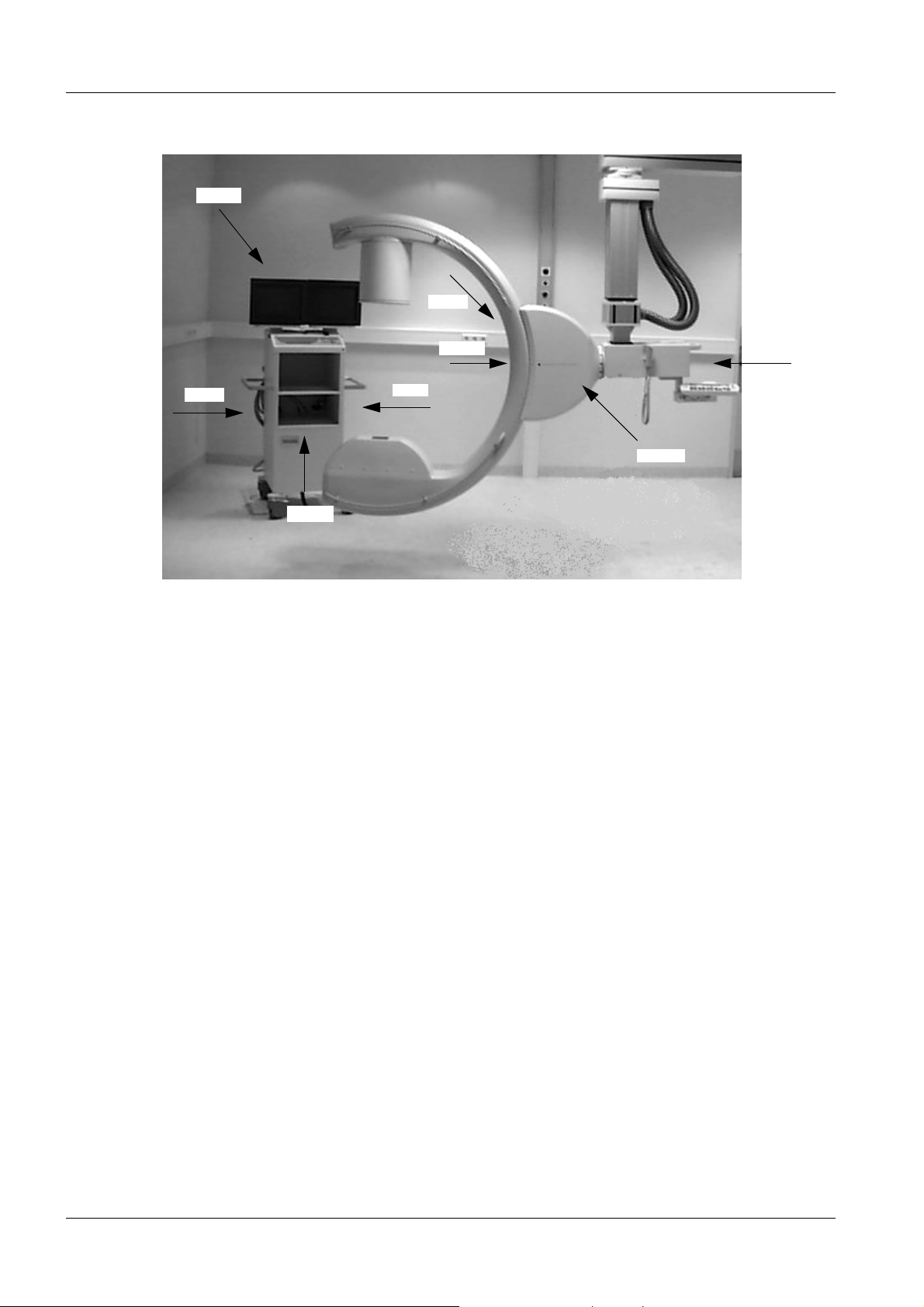
1 - 2 Prerequisites
back
left
Fig. 1
left
front
right
right
front
back
Information regarding this document 1
These service instructions will assist you in adjusting the ARCOSKOP for routine
operation. Not every adjustment is required each time the system is serviced.
Position designations 1
The designations for the monitor trolley and the ARCOSKOP used in these instructions,
i.e. left, right, front and back, are explained in Fig.1.
ARCOSKOP SPR2-250.840.01 Seite 2 von 16 Siemens AG
System Manual Rev. 01 09.05 CS PS 24 Medical Solutions
Page 9
Prerequisites 1 - 3
Safety Information 1
WAR NING
WAR NING
Danger of physical injury up to death and damage to property!
You must comply with
- the product-specific safety notes in these instructions,
- the general safety notes in the instructions
TD00-000.860.01... and
- the general safety instructions according to ARTD Part 2.
In the case of non-compliance death or physical injury or damage
to property can arise.
Electrical voltage!
In the case of non-compliance death or physical injury or damage
to property can arise.
Parts conducting voltage can be touched after covers of the
system have been removed. To avoid this danger disconnect the
system from the power supply before removing covers.
For this purpose pull out the mains plug or switch the line voltage
connection of the system free of voltage and secure it against
being switched back on. In the case of necessary service work in
connection with electrical voltage, observe the general safety
notes in the instructions TD00-000.860.01...
WAR NING
WAR NING
Electrical voltage!
In the case of non-compliance death or physical injury or damage
to property can arise.
After service work on the primary circuit of the power-up module
(e.g. replacement of the power-up module or parts of it) measure
and record the equivalent system leakage current (see system folder or logbook).
Danger of infection with pathogens!
In the case of non-compliance death or physical injury can arise.
This product is released for operation in operating rooms and can
be contaminated with infectious blood or other body secretions.
Avoid all contact with blood or other body secretions!
Comply strictly with the preventive measures against infectious
diseases specified in ARTD-002.731.37... !
Siemens AG SPR2-250.840.01 Seite 3 von 16 ARCOSKOP
Medical Solutions Rev. 01 09.05 CS PS 24 System Manual
Page 10
1 - 4 Prerequisites
WAR NING
WAR NING
CAUTION
Electrical voltage!
In the case of non-compliance death or physical injury or damage
to property can arise.
After completion of all service work and after attaching all covers
of the system perform a protective ground wire test according to
ARTD-002.731.17... . The protective ground wire resistance must
not exceed 0.2 ohms.
X-ray radiation!
In the case of non-compliance death or physical injury can arise.
The radiation protection regulations must be complied with
during service work in which X-ray radiation must be released.
Keep the radiation activity as low as possible (low kV, mA, short
radiation time).
Keep your distance from the radiation source as large as possible. Radiation protection devices (lead partitions, etc.) and radiation protection clothing (lead apron) must be used.
Danger of burns on hot modules or components! In the case of
non-compliance slight to medium burns, primarily on hands, can
occur.
CAUTION
WAR NING
After covers are removed modules or components (e.g. power
modules, heat sinks, magnetic brakes) that can have temperatures > 50° Celsius in operation can be touched. To avoid burns
switch the system free of voltage and wait for a cooling down time
of at least 5 minutes before touching modules or components.
Electrostatic voltage!
There can be damage to property in the case of non-compliance.
Comply with the ESD protection regulations in service work.
Electrical voltage!
In the case of non-compliance death or physical injury or damage
to property can arise.
The Elko batteries of the generator and the Elkos on the generator
board remain charged for a long time even after the system is
switched off. The Elkos must be discharged before working on the
Elko batteries and before working on the generator. Switch the
switch D21.S2 into the UZ_OFF position and wait until the LEDs
D21.X22 and D21.X23 no longer light up. Then check the voltage
between the test points X109.UZ_IST and X109.ANA_GND.
The voltage must be < 0.2 V (corresponds to Uz < 20 V).
ARCOSKOP SPR2-250.840.01 Seite 4 von 16 Siemens AG
System Manual Rev. 01 09.05 CS PS 24 Medical Solutions
Page 11
Prerequisites 1 - 5
CAUTION
CAUTION
Danger of injury when dismantling / assembling mechanical
parts! Non-compliance can lead to minor to medium severe injuries, especially to the hands!
If parts that are under mechanical stress have to be dismantled or
assembled, as for example the cover over the horizontal carriage
of the basic unit, inattention can cause injuries due to crushing,
cutting or grazing the skin, especially to the hands.
Perform the corresponding work with special care and attentiveness.
Wear working gloves if necessary.
Danger of injury on mechanical parts!
Non-compliance can lead to minor up to moderately severe injuries, especially to the hands!
With covers removed, you can come into contact with parts such
as flat plugs, threaded bolts, cut off cable ties or edges of components on which, in the case of inattention, injuries can arise
due to crushing, cutting or grazing the skin, especially to the
hands.
Perform the corresponding work with special care and attentiveness.
Siemens AG SPR2-250.840.01 Seite 5 von 16 ARCOSKOP
Medical Solutions Rev. 01 09.05 CS PS 24 System Manual
Page 12

1 - 6 Prerequisites
Information on the equivalent leakage current measurement 1
Regulations and scope for the subsidiaries 1
Within the scope of DIN VDE0751 part 1, the equivalent leakage current test must be performed.
Outside the scope of DIN VDE0751, the subsidiaries must observe the following:
(see ARTD-002.731.731.17, Safety regulations for installation and maintenance).
The legal national regulations apply to the subsidiaries. In the event that there are no existing regulations, observe the following rules in the interest of safety for customers, patients, employees and third parties, as well as the company.
Initial measurement 1
The measurement was performed at the factory and the value measured was recorded in
test protocol 1b. The measurement was performed with the line voltage and line frequency
specified in the test protocol. During start-up of the ARCOSKOP on-site, the values were
checked and remeasured and recorded if they deviated from the line voltage. The protocol
is filed in Register 9 of the System Manual and System Owner Manual,
Register 6.
Repeat measurements 1
When performing service or repair work in the primary circuit of the power supply, the
equivalent leakage current must be measured again and compared to the initial value
measured. The measurement setup must match the measurement setup for the equivalent leakage current / protocol. During measurement, the ARCOSKOP must be switched
on.
When using the Bender safety tester, the tester must be set to manual measurement.
The values measured during repeat tests must not exceed the original value by more than
50%. In addition, the limit of 2 mA must not be exceeded. ARCOSKOP systems which
exceed this threshold must be serviced. The values measured are to be recorded in the
equivalent leakage current / protocol (see System Manual, Register 9).
Hand over a copy of the protocol to the customer for filing in the System Owner Manual.
ARCOSKOP SPR2-250.840.01 Seite 6 von 16 Siemens AG
System Manual Rev. 01 09.05 CS PS 24 Medical Solutions
Page 13
Prerequisites 1 - 7
Fig. 2 Fig. 3
Fig. 4 Fig. 5
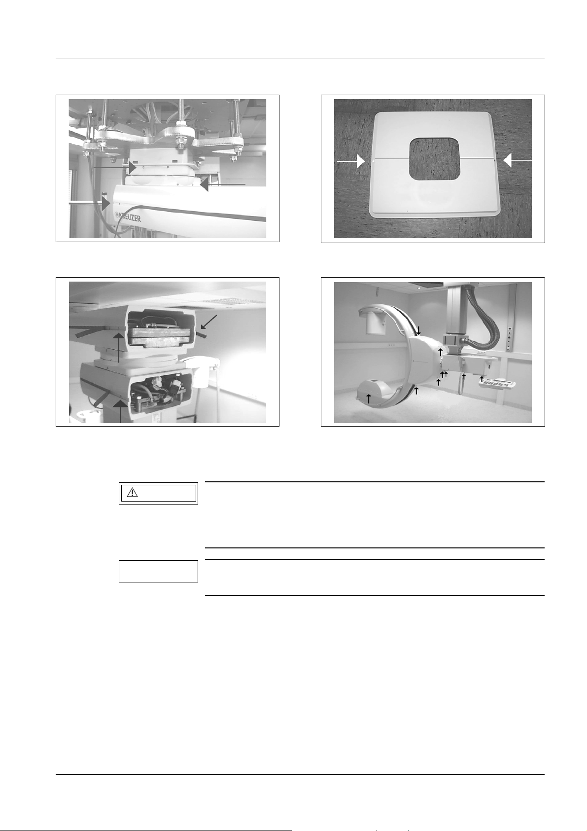
Covers 1
WAR NING
NOTE
Installing/removing the covers on the support 1
• To loosen the fastening screws for the end caps on the support arms, the rubber at the
ends must be pulled out from the slot, refer to Fig. 2 to Fig. 5. After removing the Phillips
screws, press the internally located retainer a little to the inside with a thin screwdriver
and simultaneously pull the end cap out a little. After the end cap has been loosened on
both sides it can be removed.
• To remove the two-part cover of the support on the false ceiling, remove the two white
rubber plugs and unscrew the Allen screws, refer to the figure at the right above. The two
parts must be pulled apart. Take care in this case that the two internally located retaining
Electrical voltage!
See Chapter 1, Safety Information.
Prior to removing the covers, switch off the line voltage supply to
the system and secure against accidental switch-on.
Switch off the compressed air brakes, turn off the compressed air
and let it escape.
Siemens AG SPR2-250.840.01 Seite 7 von 16 ARCOSKOP
Medical Solutions Rev. 01 09.05 CS PS 24 System Manual
Page 14

1 - 8 Prerequisites
rods remain in one half of the two covers in order to keep the space required for pulling
the halves apart small.
Installing/removing the covers on the C-arm mounting 1
• Remove the cover screws and remove both covers towards the side (Fig. 5).
• After completing the procedure, reinstall both covers in the reverse order.
ARCOSKOP SPR2-250.840.01 Seite 8 von 16 Siemens AG
System Manual Rev. 01 09.05 CS PS 24 Medical Solutions
Page 15
Prerequisites 1 - 9
Cover over the horizontal carriage 1
Fig. 6 Fig. 7
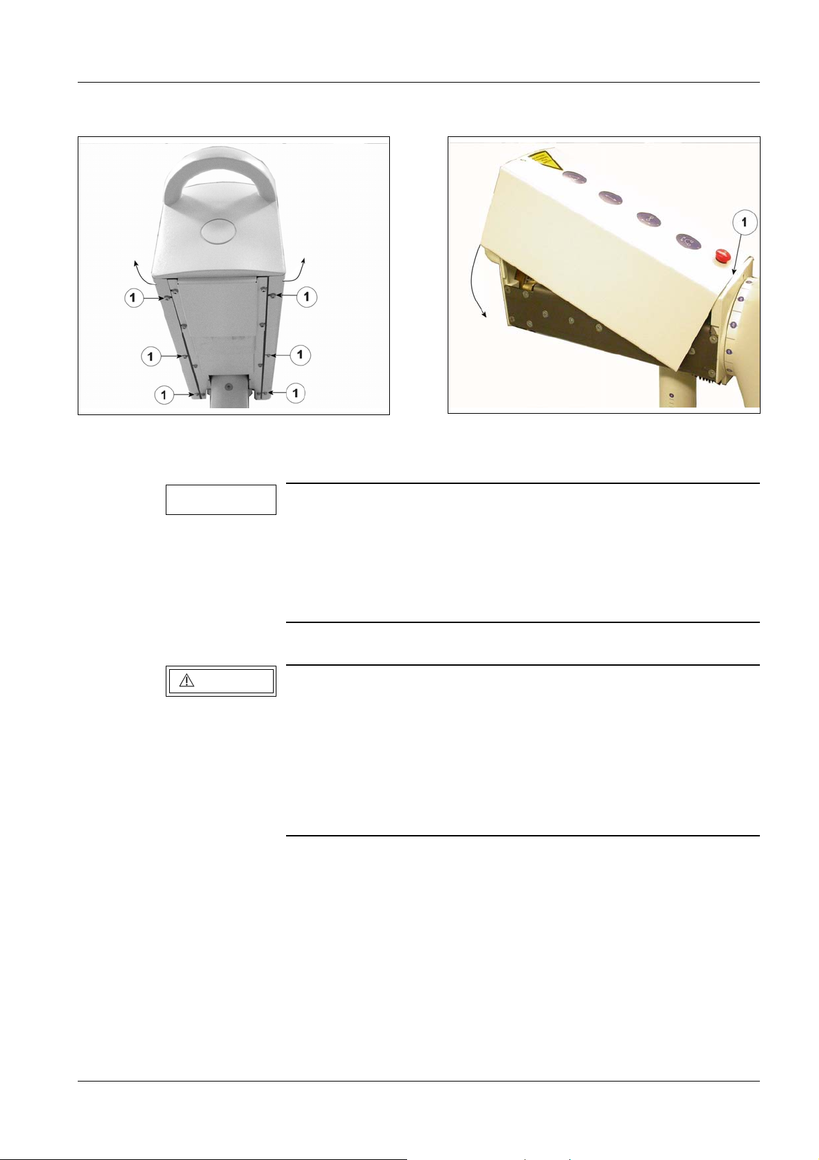
Removing the cover 1
NOTE
Fig. 6 and Fig. 7 are examples and show the cover of the SIREMOBIL Iso-C.
The cover of the ARCOSKOP horizontal carriage is open to the
front in the area of the verical lifting column and has no emergency stop button and only 3 brake buttons.
However, the cover of the ARCOSKOP can be removed and attached in practically the same way.
• Loosen the 6 mounting screws (1/Fig. 6).
CAUTION
Danger of injury when dismantling / assembling mechanical
parts! Non-compliance can lead to minor up to moderately severe
injuries, especially to the hands!
The cover over the horizontal carriage is bent U-shaped and must
be pulled on the side to the outside when it is removed.
The cover is then under mechanical stress.
We recommend that you wear light working gloves to avoid injuries.
• Expand the cover at the rear end in the direction of the arrow (see Fig. 2) and remove it
downwards.
• If needed disconnect the protective ground wire, the cable of the keypad (brake buttons)
and the cable of the emergency stop button.
Siemens AG SPR2-250.840.01 Seite 9 von 16 ARCOSKOP
Medical Solutions Rev. 01 09.05 CS PS 24 System Manual
Page 16

1 - 10 Prerequisites
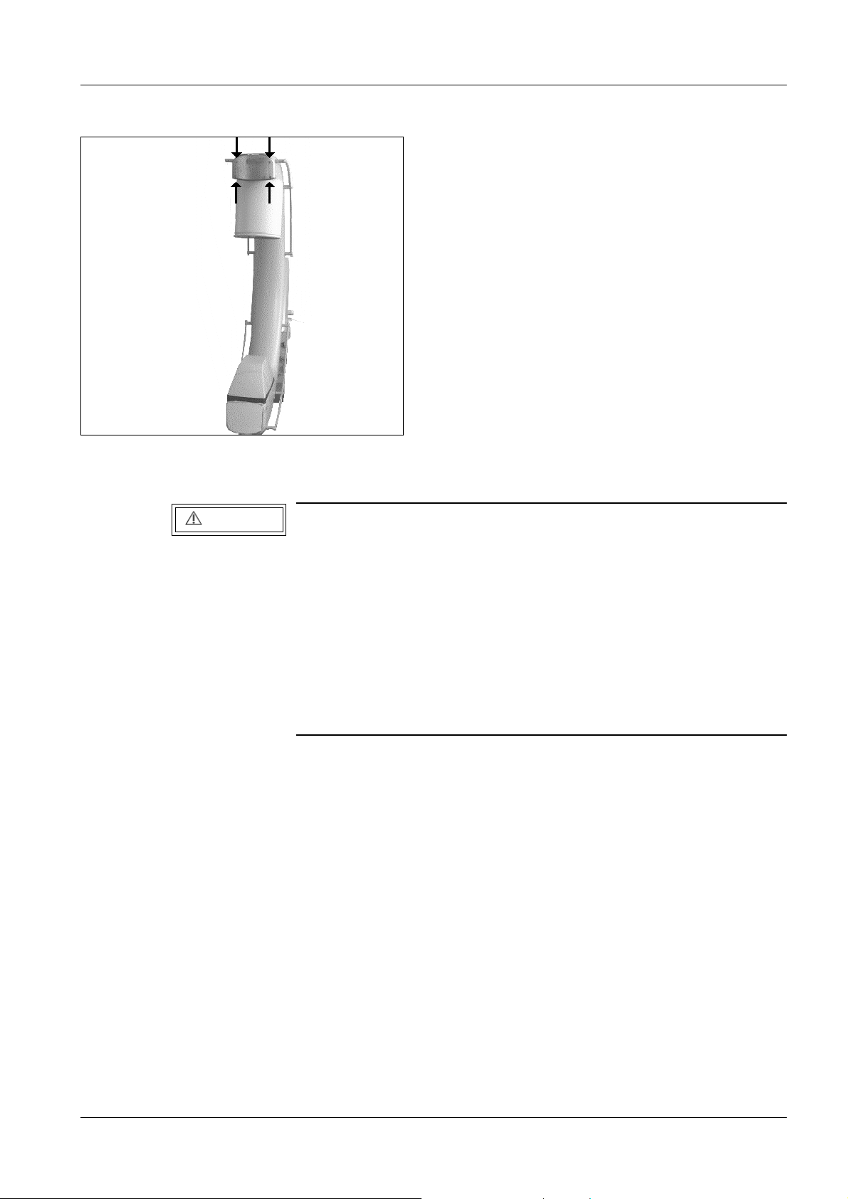
Attaching the cover 1
• Re-fasten or connect the protective ground wire, the cable of the keypad (brake buttons)
and the cable of the emergency stop button.
CAUTION
Danger of injury when dismantling / assembling mechanical
parts! Non-compliance can lead to minor up to moderately severe
injuries, especially to the hands!
When the cover is attached and pressed down, it is under mechanical stress and snaps into place over the bottom edge of the
horizontal carriage.
Expand the cover at the rear end (see Fig. 6) so far that as shown
in Fig. 7 it lies obliquely over the horizontal carriage in the edge 1/
Fig. 7.
Press on the surface on the top of the cover, without grasping the
sheet metal edges, until this slides over the lower edge of the
horizontal slide.
• Expand the cover at the rear end (see Fig. 6) so far that as shown in Fig. 7 it lies obliquely
over the horizontal carriage in the edge 1/Fig. 7.
• Press on the top surface of the cover, without grasping the sheet metal edges, until this
slides over the lower edge of the horizontal slide. Here make sure that the cover does not
slide out from the edge (1 / Fig. 7).
• Check the operation of the emergency stop button and of the brake buttons.
• Fasten the cover with the 6 Allen screws (1/ Fig. 6).
ARCOSKOP SPR2-250.840.01 Seite 10 von 16 Siemens AG
System Manual Rev. 01 09.05 CS PS 24 Medical Solutions
Page 17
Prerequisites 1 - 11
Fig. 8
Installing/removing the cover at the C-arm/I.I. side 1
CAUTION
Danger of injury!
In the case of non-compliance death or physical injury or damage
to property can arise.
The C-arm cover contains counterbalance weights and weighs
> 10 kg.
Hold the cover firmly when installing or removing it.
Before the C-arm cover is loosened, the C-arm must be moved to
its middle orbital position.
If the C-arm covers are loosened, the C-arm must not be moved to
its orbital end positions (I.I. or POWERPHOS in the orbital end
position).
• Remove the 4 fastening screws (Fig. 8). Hold the covers firmly while removing them.
• Install them in the reverse order.
Siemens AG SPR2-250.840.01 Seite 11 von 16 ARCOSKOP
Medical Solutions Rev. 01 09.05 CS PS 24 System Manual
Page 18
1 - 12 Prerequisites
Monitor trolley 1
Removing the covers
• Remove the upper back cover plate of the log book compartment.
• Remove the protective ground wire.
• Remove the lateral Allen screws from the lower back cover.
• Remove the protective ground wire from the cover.
Installing the covers
• Begin with the lower back cover.
• Reattach the protective ground wire for the lower cover.
• Install the cover and tighten the screws.
• Reattach the protective ground wire for the log book compartment.
• Install the cover and tighten the screws.
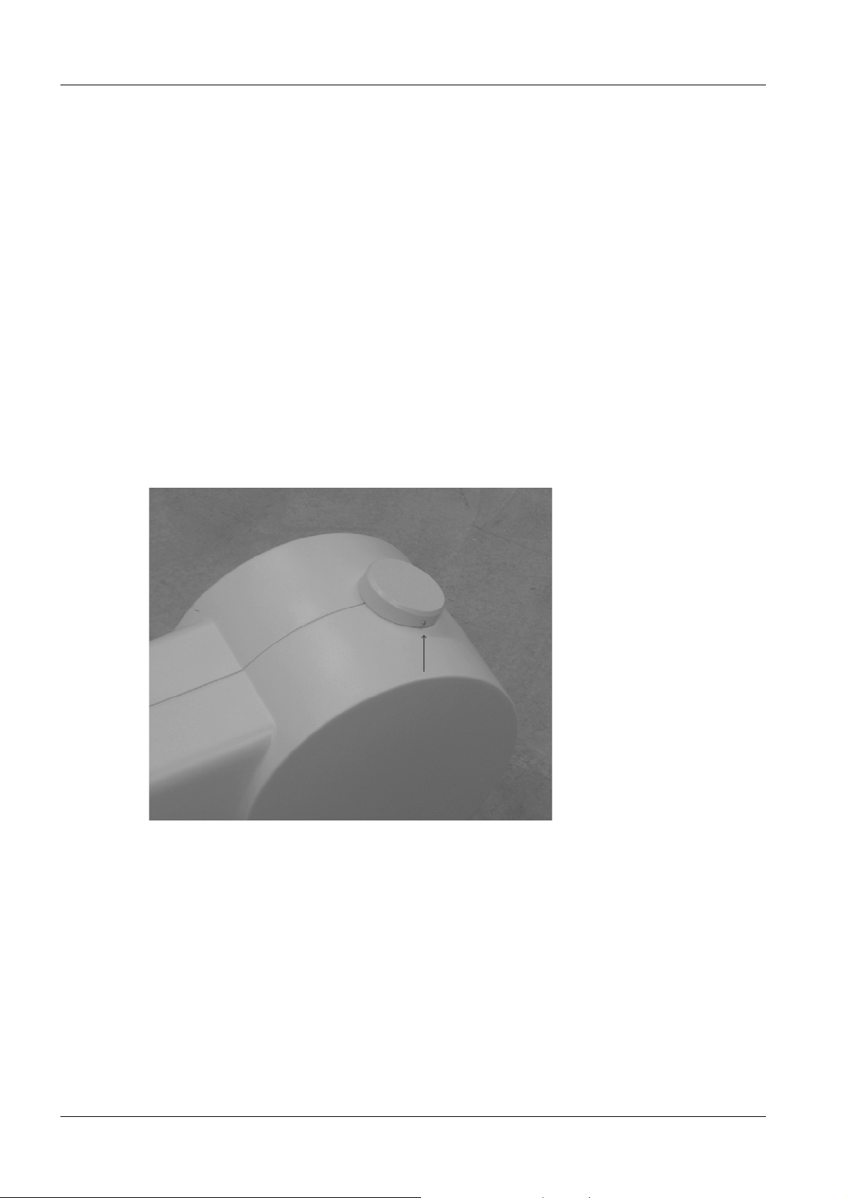
Installing/ removing the covers on the monitor support system 1
Fig. 9 Monitor support system cover 1-2
• Remove the screw fastening of the cover halves on the upper joint of the cover,
see arrow Fig. 9.
• Loosen the remaining cover screws and remove the two cover halves to the side.
• After taking the necessary action install the covers again in the reverse order.
ARCOSKOP SPR2-250.840.01 Seite 12 von 16 Siemens AG
System Manual Rev. 01 09.05 CS PS 24 Medical Solutions
Page 19
Prerequisites 1 - 13
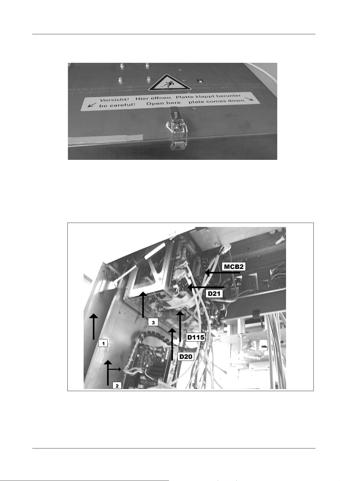
Service position for the board access of the electronics box 1
Fig. 10
• The cover latch must be closed before loosening the screws (see Fig. 10).
• Remove the screws from the sides of the cover (see Fig. 10).
• Be aware of the weight added by the components attached to the rear side when opening
the latch and the service cover (see 2/Fig. 11).
Fig. 11
• You can now lower the generator unit. Use an extension to loosen the two screws on the
upper sides (see 3/Fig. 11).
Siemens AG SPR2-250.840.01 Seite 13 von 16 ARCOSKOP
Medical Solutions Rev. 01 09.05 CS PS 24 System Manual
Page 20
1 - 14 Prerequisites
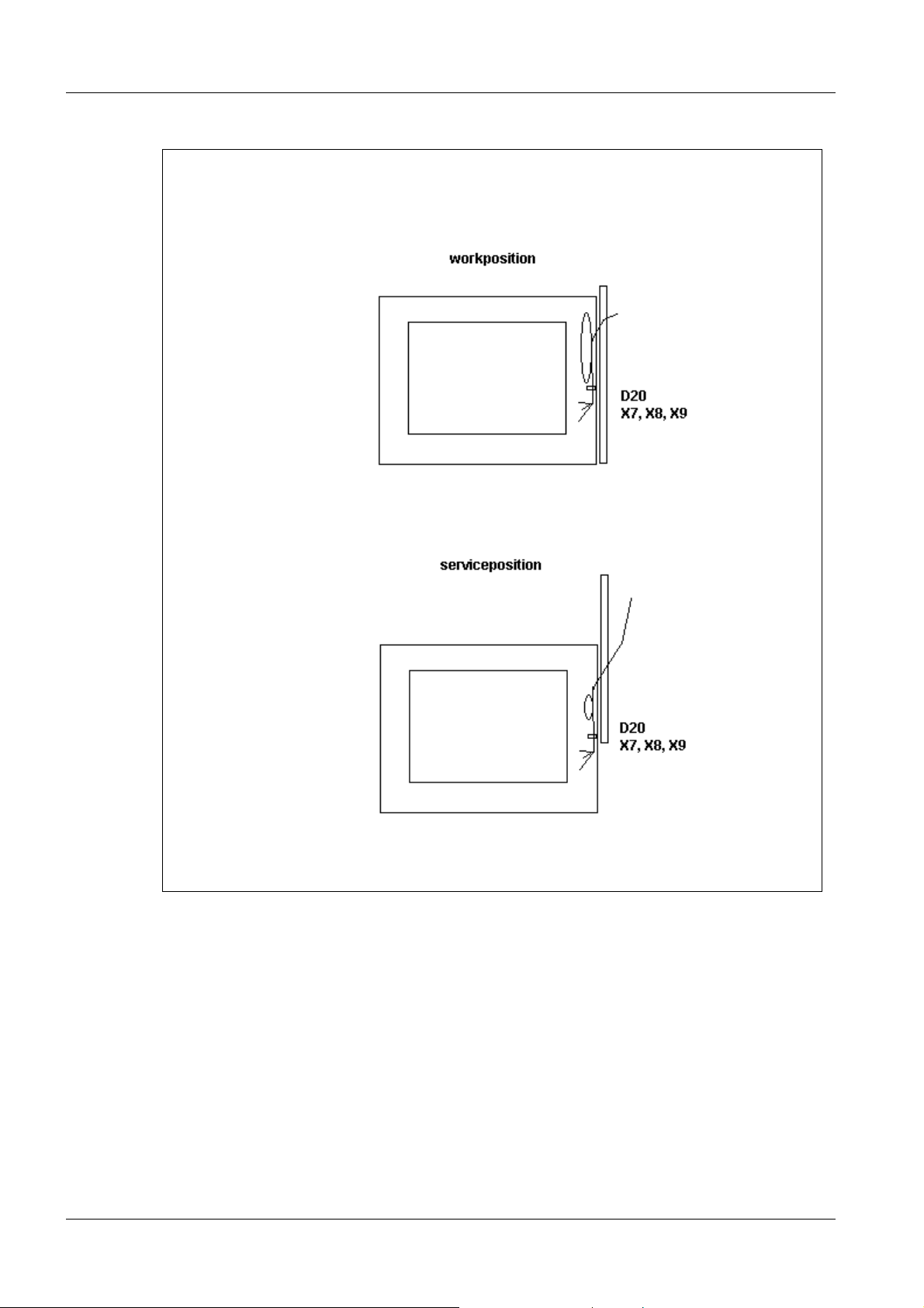
Fig. 12
• Cables D20, X7, X8, and X9 should be fastened to the cable clamps with a torque of
4.8 Nm. Loop the cables and attach the shield as shown in Fig. 12. Ensure that the
cables do not become crimped or torn when moving the generator.
• When routing cables in the E-box, ensure that the cover can be opened and closed
without crimping or stretching the cables or loosening the plug connection.
ARCOSKOP SPR2-250.840.01 Seite 14 von 16 Siemens AG
System Manual Rev. 01 09.05 CS PS 24 Medical Solutions
Page 21
Prerequisites 1 - 15
Fig. 13 Fig. 14
Fig. 15
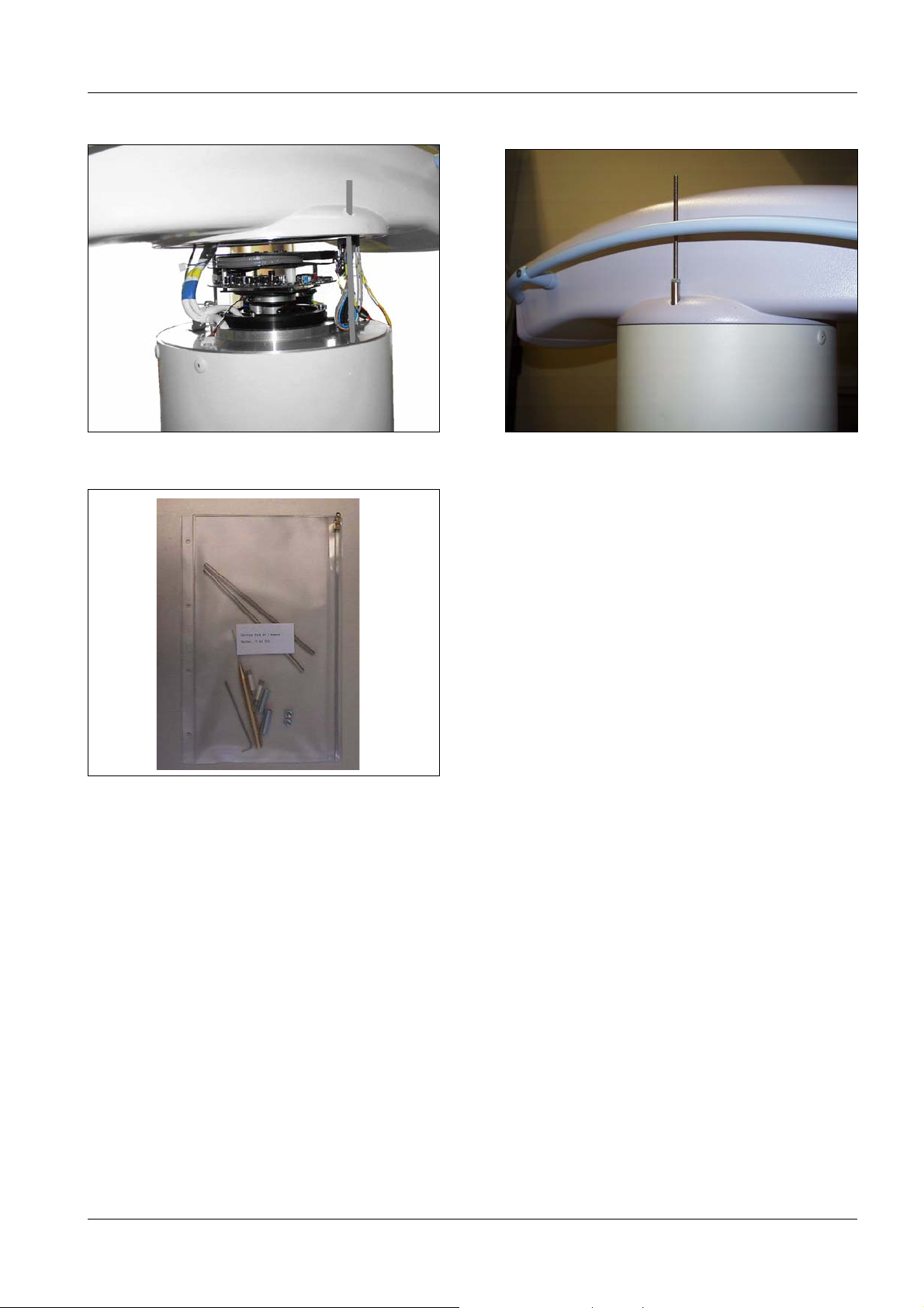
I.I. service position 1
Moving the I.I. into the service position 1
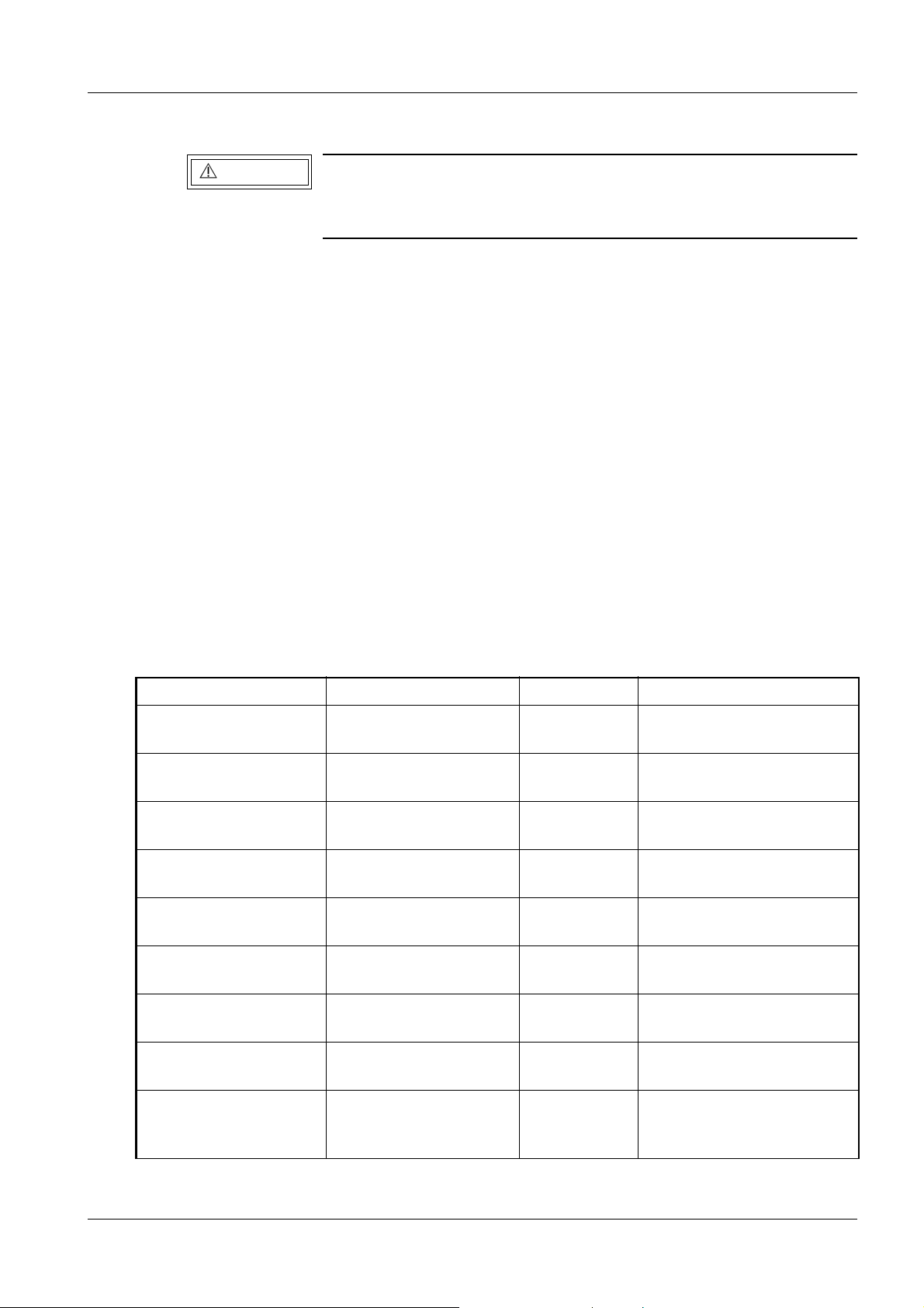
• Take the threaded rods, spacers and nuts out of the accessory pack ("Service Pack I.I./
Camera" part no. 71 43 519 / Fig. 15).
• Move the C-arm into the vertical position, with the I.I. below and the POWERPHOS
above.
• Remove both attachment screws for the I.I. and replace them with the threaded rods
from the service pack.
• Insert the threaded rods from the service pack at least 5 turns into the threaded holes of
the I.I.
• Then mount the spacers and nuts (see Fig. 14).
• Tighten the nuts to fasten the I.I. again.
Siemens AG SPR2-250.840.01 Seite 15 von 16 ARCOSKOP
Medical Solutions Rev. 01 09.05 CS PS 24 System Manual
Page 22

1 - 16 Prerequisites
• Turn the C-arm so that the I.I. is above and the POWERPHOS is below (angulation).
• Lower the I.I. by gradually loosening the nuts alternately. Be careful not to damage the
cables. Fig. 13 shows the I.I. in the service position.
Installing the I.I. 1
• Lift the I. I. a little alternately on each side and retighten the nuts.
Repeat this until the I.I. is fastened again. Be careful not to damage the cable.
• Tighten the nuts to fasten the I.I. again.
• Move the C-arm so that the POWERPHOS is above and the I.I. is below (angulation).
• Remove the two threaded rods (service pack) again from the threaded holes of the I.I.
and reinstall the I.I. with the two attachment screws.
ARCOSKOP SPR2-250.840.01 Seite 16 von 16 Siemens AG
System Manual Rev. 01 09.05 CS PS 24 Medical Solutions
Page 23
Power supply adaptation 2
2 - 1
WAR NING
Electrical voltage!
See Chapter 1, Safety Information.
Disconnect the ARCOSKOP power plug.
• Open the back cover of the monitor trolley.
• Measure the on-site line voltage and line frequency.
• Adjust transformer T1 to the required line voltage and line frequency. Refer to the label
on the switch-on assembly.
• Adjust transformer T2 to the required line voltage and line frequency. Refer to the label
on the switch-on assembly.
• Check fuses F1 and F2 to see as to whether they correspond with the values on the label
of the switch-on assembly and replace them, if necessary.
• Mark the correct line voltage and line frequency on the line voltage label at the back of
the monitor trolley.
Checking the line voltages on the monitor trolley 2
• Plug X10 for the basic unit must be disconnected.
• The monitor, memory device and other devices, if present, such as multiformat camera,
video printer or video recorder must be disconnected from the line voltage supply.
• Check the secondary voltages for line voltage transformer T1 according to table 1.
From test point to test point Voltage Comment
Transformer T1.31 Transformer T1.32 190 V ~ to
205 V ~
Transformer T1.31 Transformer T1.33 230 V ~ to
246 V ~
Power cable
Memoskop, N
Power cable
Monitor 1, N
Option: Power cable
Monitor 2, N
Option: Power cable
Multispot, N
Option: Power cable
Video printer, N
Option: Power cable
Video recorder, N
Option
Power cable optical
video separation, N
Power cable
Memoskop, L
Power cable
Monitor 1, L
Power cable
Monitor 2, L
Power cable
Multispot, L
Power cable
Video printer, L
Power cable
Video recorder, L
Power cable optical
video separation, L
230 V ~ to
246 V ~
230 V ~ to
246 V ~
230 V ~ to
246 V ~
230 V ~ to
246 V ~
230 V ~ to
246 V ~
230 V ~ to
246 V ~
230 V ~ to
246 V ~
if Video printer present, not
not adjustable
not adjustable
not adjustable
not adjustable
not adjustable
if Multispot present, not
adjustable
adjustable
if Video recorder present,
not adjustable
if optical video separation
present, not adjustable
Tab. 1
Siemens AG SPR2-250.840.01 Seite 1 von 2 ARCOSKOP
Medical Solutions Rev. 01 09.05 CS PS 24 System Manual
Page 24

2 - 2 Power supply adaptation
Diese Seite wurde bewusst leer gelassen.
ARCOSKOP SPR2-250.840.01 Seite 2 von 2 Siemens AG
System Manual Rev. 01 09.05 CS PS 24 Medical Solutions
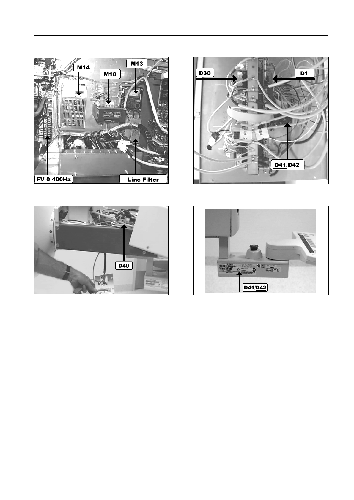
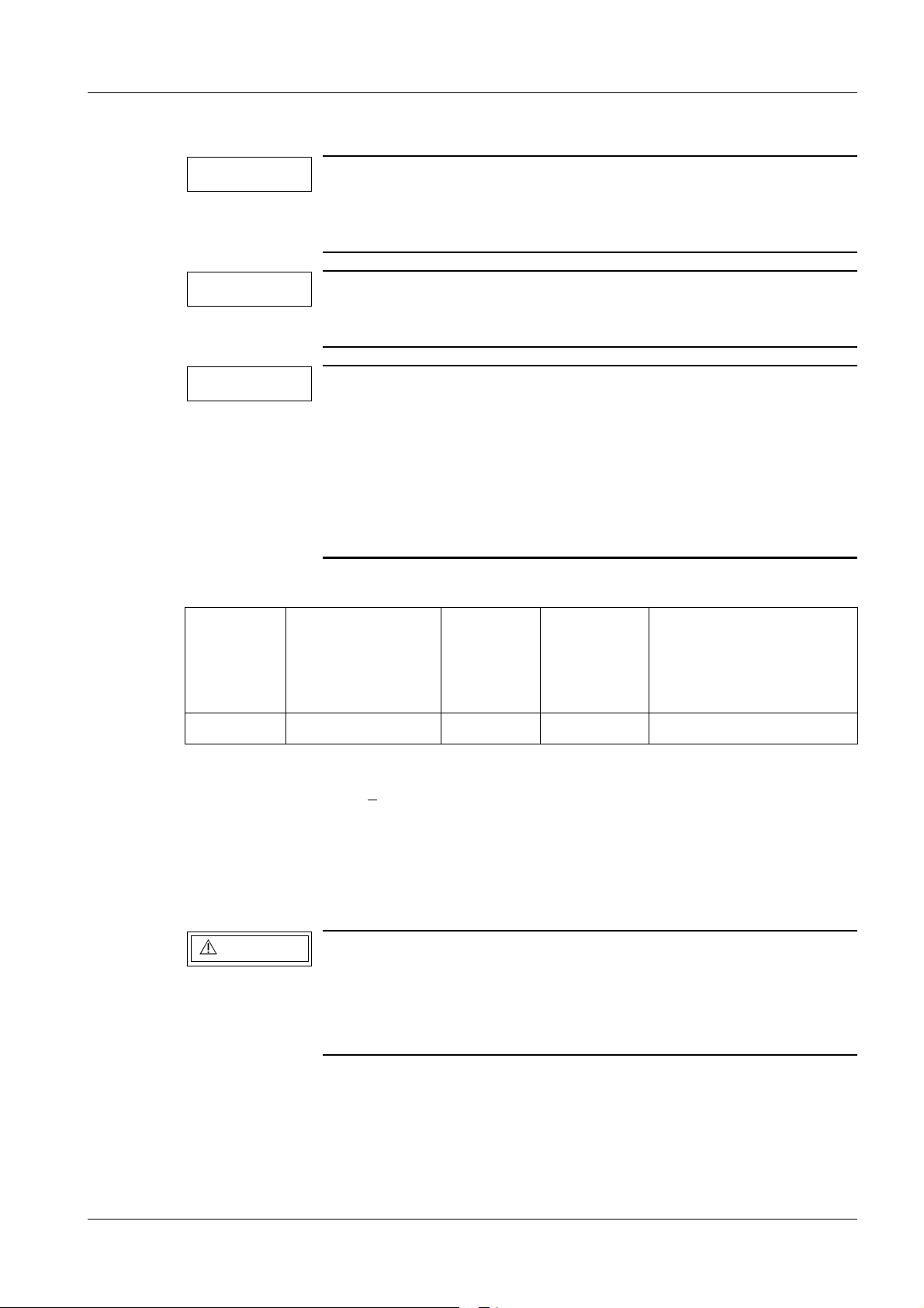
Page 25
Checking the operating voltages 3
Fig. 1 Fig. 2
3 - 1
Fig. 3 Fig. 4
Siemens AG SPR2-250.840.01 Seite 1 von 4 ARCOSKOP
Medical Solutions Rev. 01 09.05 CS PS 24 System Manual
Page 26
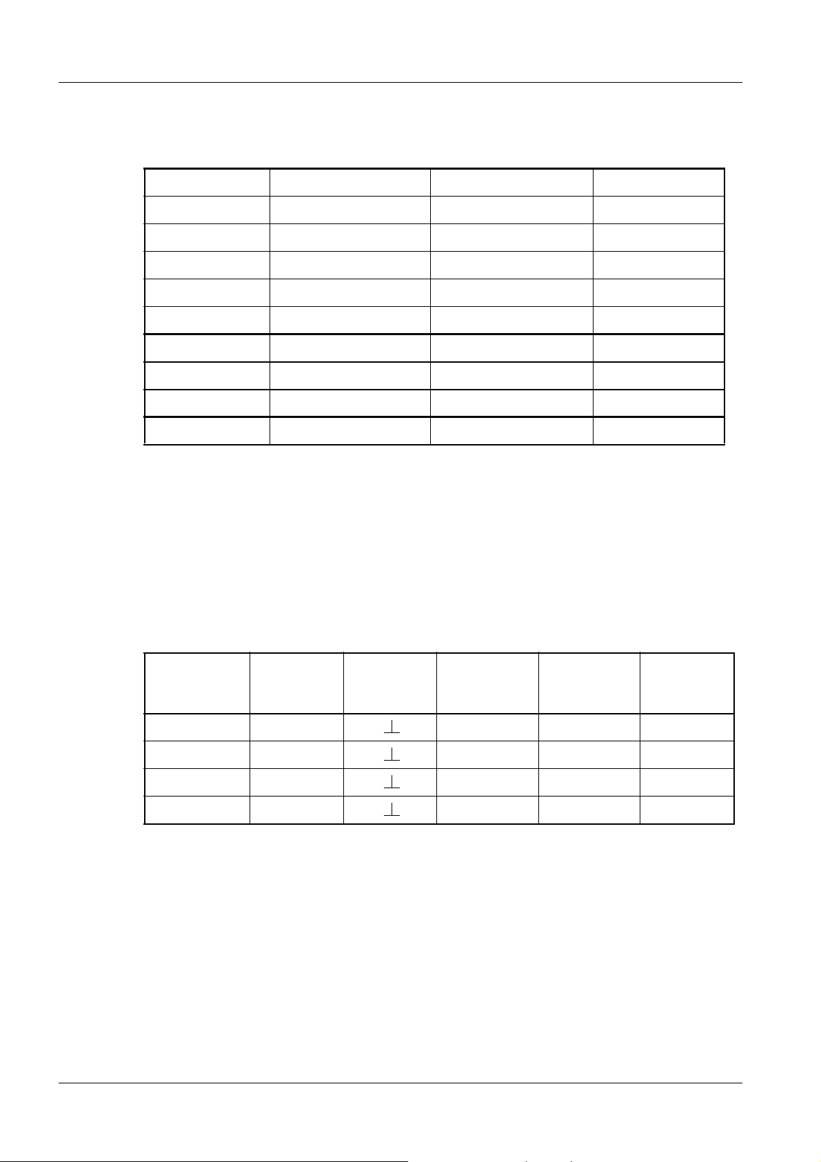
3 - 2 Checking the operating voltages
Low voltages 3
• Check the operating voltages of the ARCOSKOP according to tables 1 and 2 (Fig.1 - 4).
From test point To test point Voltage Adjuster
D1.X37 (0V) D1.X30 (+5 V) +5.1 V to 5.2 V M14. +5 V/Adj.
D1.X39 (0V) D1.X32 (+15 V) +4.9 V to 15.1 V M14. +15 V/Adj.
D1.X39 (0V) D1.X33 (-15 V) - 4.8 V to -15.2 V M14. -15 V/Adj.
D30.X1.8 (0V) D30.X1.9 (+24 V) +24.0 V to 29.6 V not adjustable
D30.X21.1 (0V) D30.X21.10 (+24 V) +22.8 V to +29.5 V not adjustable
D30.X20.1 (0V) D30.X20.3 (+27 V) +27.3 V to +27.8 V D30 R115
D42.MP1 (0V) D42.MP2 (+5 V) + 5,0 V bis +5,2 V D40.P1
D40.D17.A (0V) TP (+5 V) +5,0 V to +5,2 V D40.P1 *1
M13.S- (0V) M13.S+ (+13 V) +13.1 V to 13.3 V M13.TR1
Ta b . 1
*1
With existing "operation free" option, i.e. the control console is detachable, you must measure and check on board D40 that the voltage does not exceed 5.2 V. Should the voltage
on D40 be too high, the voltage on D42 can be reduced to 5.0 V.
Image intensifier voltages 3
• Take the voltages E1 / E2 / E3 and A from the test protocol of the image intensifier and
check or adjust them at the test points of the control unit listed in Table 2.
Voltage Test point Ground
point (0V)
E1 UE1 P10 P11 1:1
E2 UE2 P6 P7 1:1
E3 UI 15 P2 P3 1:10000
30 kV, anode UI 30 P1 P1 1:10000
Ta b . 2
Potentiome-
ter for
full format
Potentiome-
ter for
zoom format
Volt ag e d ivi -
der ratios
ARCOSKOP SPR2-250.840.01 Seite 2 von 4 Siemens AG
System Manual Rev. 01 09.05 CS PS 24 Medical Solutions
Page 27

Checking the operating voltages 3 - 3
D41/D42 Programming 3
• Make sure that the jumpers on boards D41 and D42 are installed as follows:
Board Jumper Pins on off Components
D41 21 1 - 2 X E-Box
D41 22 1 - 2 X E-Box
D41 23 2 - 3 X E-Box
D41 24 X E-Box
D41 25 X E-Box
D41 26 X E-Box
D42 21 2 - 3 X Panel
D42 22 2 - 3 X Panel
D42 23 1 - 2 X Panel
D42 24 X Panel
D42 25 X Panel
D42 26 X Panel
Tab. 3
• Board D41 for the E-box and board D42 for the control panel have to be clearly identified
with an X in the respective field.
Siemens AG SPR2-250.840.01 Seite 3 von 4 ARCOSKOP
Medical Solutions Rev. 01 09.05 CS PS 24 System Manual
Page 28

3 - 4 Checking the operating voltages
Diese Seite wurde bewusst leer gelassen.
ARCOSKOP SPR2-250.840.01 Seite 4 von 4 Siemens AG
System Manual Rev. 01 09.05 CS PS 24 Medical Solutions
Page 29

Operating software 4
Loading the operating software 4
• Connect the service PC to the serial service interface on ARCOSKOP.
• Insert the "Parameter" disk in drive A.
• Start the service program.
• Select the Download menu, select the relevant file (Host, Gen....) and start Download.
• After successfully downloading, wait for the system to boot (1 minute).
• The ARCOSKOP is operational.
4 - 1
NOTE
If you cannot run Download (e.g. power failure during Download):
- Switch the ARCOSKOP off and back on
- Restart Download
Backing up the system parameters 4
NOTE
Prerequisite:
The service PC is already connected, the service program is already started.
• Select the "Data" menu.
• Select the "Backup" submenu.
• Click the "Parameter" check box.
• If required select the back-up of further data by selecting the corresponding check box.
After changing settings / parameters, back these up on the parameter disk.
Note that the data are stored correctly only after ending the service program
Therefore always exit the service program with "Logoff" and
"Quit".
• Click the "Backup" button. Wait until the data are backed up temporarily on disk.
• Then back to the main menu.
• Select the "System" menu.
• Select the "Logoff" submenu. Wait until the data are stored on disk.
• You can now exit the service program by selecting the "System" and "Quit" menus.
Siemens AG SPR2-250.840.01 Seite 1 von 4 ARCOSKOP
Medical Solutions Rev. 01 09.05 CS PS 24 System Manual
Page 30

4 - 2 Operating software
Reading and storing the load counter data 4
NOTE
The procedure is divided in 4 steps:
Before the replacement of the POWERPHOS, all load counter
values have to be stored on disk. After storing the load counter
values, the load counter has to be reset. All values are set to 0.
After the replacement and all adjustments, send back the disk
with the defective POWERPHOS for repair.
• Store the actual load counter values on disk.
• Release the resetting of the load counters.
• Reset the load counter values to 0.
• Return the defective POWERPHOS, including the load counter data disk.
Storing the actual load counter values 4
• Connect the service PC to the serial interface of the unit.
• Start the service program.
• Select the "Diagnostics / Monitoring" menu.
• Select "LOAD COUNTERS" in the "Group 1:" combo box.
• Click on "Update Start" and wait until the actual values are displayed.
• Click on "Update Stop".
• Click on the "Save" button.
• Change the data disk of the service program in drive A against a formatted empty one.
• Select the drive A for storage.
• For the file name, enter the current date, the part no. and the serial no. of the
POWERPHOS.
Example:
The current date is:
Use the date format DD-MM-YY:
The POWERPHOS part no. is:
The POWERPHOS serial no. is:
Enter the file name:
08-22-1999
22-08-99
55 73 501
01234
22-08-99_5573501_01234.his
• Store the file on disk.
• After storage, change the disk in drive A against the previously used data disk of the
service program.
• Close the Monitoring window by clicking on the "Cancel" button.
ARCOSKOP SPR2-250.840.01 Seite 2 von 4 Siemens AG
System Manual Rev. 01 09.05 CS PS 24 Medical Solutions
Page 31

Operating software 4 - 3
Releasing the resetting of the load counter values 4
• Select the "Adjustment / Parameters..." menu.
• Select "SETTINGS FOR SERVICE PC" in the "Parameter Groups:" combo box.
• Click on the "Get from Unit" button.
• Select the parameter "ENABLE RESET TUBE VALUES".
• In the "Value / Actual" field, select "YES".
• Click on the "Set Value" button.
• Click on the "Put to Unit" button.
• Answer the query with "YES" and wait until the unit has rebooted.
• Close the Parameters window by clicking on the "Cancel" button.
Resetting the load counters 4
• Select the "Adjustment / Calibrations..." menu.
• Answer the query with "YES".
• Select "RESET TUBE VALUES" in the "Function Groups:" combo box.
• Select "LOAD COUNTER" and click on "Execute".
• The load counters are set to 0.
• Close the Status window by clicking on the "OK" button.
• Answer the query "Do you want to reset the Unit" with "Yes".
Returning the defective POWERPHOS incl. load counter data disk 4
• Mark the load counter data disk label with:
the current date
the system part no (ARCOSKOP)
the system serial number
the POWERPHOS part number and
the POWERPHOS serial number.
• Add the disk to the defective POWERPHOS and send it all back for repair together with
the completed tube questionnaire.
Siemens AG SPR2-250.840.01 Seite 3 von 4 ARCOSKOP
Medical Solutions Rev. 01 09.05 CS PS 24 System Manual
Page 32

4 - 4 Operating software
Storing the error log in ASCII format 4
• When storing the error log using the backup function of the service program, it will be
stored as a binary file which cannot be read by a text editor.
• For easier evaluation of the error log, it can be stored in ASCII format as well.
• For easier service support from the USC or HSC, please send the error log as an ASCII
file.
NOTE
The parameter disk must be in drive A before starting the service
program and during service work. Otherwise, the text "no error
text available" will display behind the error codes instead of the
actual error messages.
Prerequisites 4
• The service PC is connected and the service program is started.
• Select the "Diagnostics..." menu.
• Select the "Error log" menu.
• Click the "Get from unit" button. Wait until the error log is transferred to the service PC.
• Click the "Export to file" button.
• Save the file to your hard drive.
• For the file name, please enter the current date, the part number and the serial number of
the unit as described in the example.
Example:
The current date is (DD-MM-YY): 29-03-01
The unit part no. is: 4774019
The unit serial no. is: 01234
Enter this file name: 22-03-01_4774019_01234.txt
• Save the file to the hard drive of your service PC under a path of your choice.
• Exit the service program.
• Copy the previous stored file to an emty, formatted floppy disk.
ARCOSKOP SPR2-250.840.01 Seite 4 von 4 Siemens AG
System Manual Rev. 01 09.05 CS PS 24 Medical Solutions
Page 33

Adjustments / Programming 5
Generator adjustment 5
5 - 1
NOTE
The mAs counter adjustment must be performed immediately
after the generator adjustment.
• Cover the radiation exit window with a lead cover or a folded lead apron.
WAR NING
X-ray radiation!
See Chapter 1, Safety Information.
Use radiation protection.
Wear a lead apron when making adjustments! Maintain a safe
distance!
• Select the DIAGNOSTICS - MONITORING menu.
• Select "GENERATOR ADJUSTMENT" in the "Group 1" combo box.
• Click on "Update Start".
➪ The collimator closes automatically.
• After about 5 seconds, press the radiation release button on the hand control or the
ARCOSKOP fluoroscopy foot switch.
NOTE
When the generator adjustment begins, continue pressing the
radiation release button until the "Stop monitoring" message
appears in the "ACTIONS" line. If the radiation release button is
released too soon, the entire generator adjustment will have to be
repeated.
Exception: Briefly releasing the radiation release button (less
than 30 seconds) is permitted during the warm-up phase of the
POWERPHOS (the message "Warm-up" appears in the "Status"
line on the service PC). The generator adjustment will continue if
the radiation release button is pressed again within 30 seconds.
➪ After approximately 8 minutes, the message "Learning pushfactor" appears.
➪ A maximum of 15 exposures is automatically released.
➪ When the generator adjustment has been successfully completed, the message
"Learning done" appears in the status display.
➪ The message "Stop monitoring" then appears in the status line.
• Click on "Update Stop".
Concluding tasks
• Perform the mAs counter adjustment.
• Switch the ARCOSKOP off and then on again.
Siemens AG SPR2-250.840.01 Seite 1 von 42 ARCOSKOP
Medical Solutions Rev. 01 09.05 CS PS 24 System Manual
Page 34

5 - 2 Adjustments / Programming
mAs counter adjustment 5
NOTE
The mAs counter adjustment must also be performed after the
generator adjustment.
• Cover the radiation exit window with a lead cover or a folded lead apron.
WAR NING
X-ray radiation!
See Chapter 1, Safety Information.
Use radiation protection.
Wear a lead apron when making adjustments! Maintain a safe
distance!
• Select the DIAGNOSTICS - MONITORING menu.
• Select "MAS COUNTER ADJUSTMENT" in the "Group 1" combo box.
• Click on "Update Start".
➪ The collimator closes automatically.
• After about 5 seconds, press the radiation release button on the hand control or the
ARCOSKOP fluoroscopy foot switch.
NOTE
When the mAs-counter adjustment begins, continue pressing the
radiation release button until the message "Stop monitoring"
appears in the "ACTIONS" line. If the radiation release button is
released too soon, the mAs-counter adjustment will have to be
repeated.
➪ A maximum of 9 exposures is automatically released.
➪ When the mAs-counter adjustment has been successfully completed, the mes-
sage "Stop monitoring" appears in the status line.
• Click on "Update Stop".
Concluding tasks
• If no other adjustments or settings need to be made, save the learned data to a disk
(Data menu - Backup on the Service PC).
• Perform the checking of the generator adjustment, see next page.
ARCOSKOP SPR2-250.840.01 Seite 2 von 42 Siemens AG
System Manual Rev. 01 09.05 CS PS 24 Medical Solutions
Page 35

Adjustments / Programming 5 - 3
Checking the generator adjustment 5
• Select the DR operating mode.
• Temporarily set K-factor to K = 1 (= EB).
• Select the HC 2 or HC 3 characteristic curve.
• Select the ->0<- key on the basic unit control console.
• Select kV Stop.
• Set 75 kV ± 1 kV with the kV+ / kV- keys.
• These default settings give a 200 mA pulsed current.
• Connect a storage oscilloscope to the test points for "kV_Ist" (D21.X118. kV_IST) and
"mA_IST" (D21.X118. I_T_IST). Ground: D21.X118.ANA_GND.
• Store and evaluate the oscillogram:
Tolerances for the mA curve
- 5 ms after pulse start to 5 ms before pulse
end:
- during the last 5 ms before pulse end:
± 20 %
± 10 %
• If the tube current exceeds the specified tolerances, the generator setup and the mAs
counter adjustment must be repeated.
Siemens AG SPR2-250.840.01 Seite 3 von 42 ARCOSKOP
Medical Solutions Rev. 01 09.05 CS PS 24 System Manual
Page 36

5 - 4 Adjustments / Programming
Dose rate adjustment 5
NOTE
There are 2 methods to set the dose rates.
• Automatic dose rate adjustment: with this method the dose rate
needs only to be set for the DR operating mode and dose rate
level HIGH in the full format. All other dose rate levels and the
necessary TV iris diaphragm values are automatically calculated
and stored.
After the automatic dose rate adjustment, perform
"Calibrating the TV iris diaphragm for automatic iris diaphragm
regulation (AIR)", Chapter 5.
Then all dose rate values must be checked according to
"Checking the set dose or dose rate", Chapter 5. If the dose or
dose rate values deviate from the nominal values by more than
the permissible tolerance, the dose rate adjustment must be
repeated according to "Manual dose rate adjustment" of
Chapter 5.
• Manual dose rate adjustment: with this method about 40 dose
rate values must be set for the different operating modes.
Use this method only if automatic dose rate adjustment is not
successful.
Automatic dose rate adjustment 5
Preparing the service PC 5
• Switch the system on.
• Connect the service PC to the serial interface of the system.
• Start the service program, the parameter disk must be inserted in drive A.
• Select the "Diagnostics..." menu.
• Select the "Monitoring..." menu.
• Select the "DOSERATE ADJUSTMENT" menu in the combo box "Group 1".
• Select "Update Start".
ARCOSKOP SPR2-250.840.01 Seite 4 von 42 Siemens AG
System Manual Rev. 01 09.05 CS PS 24 Medical Solutions
Page 37

Adjustments / Programming 5 - 5
The following messages are displayed on the service PC:
AUTO REGULATION displays the current status during the adjustment.
(active / not active / not ready / done)
ADJUSTMENT displays the regulation operating mode.
(Generator / Camera iris / Stop)
ACTUAL MODE displays the operating mode currently selected.
(FL/ PFL/DR/EB/SUB)
II. ZOOM STATUS displays the current I.I. format.
(Full format / Zoom format)
DOSE ADJ. NOMINAL VAL displays the nominal values for the dose rate.
(see Menu Adjustments... - Parameter - DOSE ADJ.
(respective operating mode) - NOMINAL VALUES )
DOSE LEVEL displays the dose rate level selected.
(Low / Mid / High)
TV IRIS ACTUAL POSITION displays the current position of the TV iris.
NOTE
After clicking on "Update Start" on the service PC, the primary
up-to-date operating statuses (see above) will be displayed
during the dose rate adjustment.
Siemens AG SPR2-250.840.01 Seite 5 von 42 ARCOSKOP
Medical Solutions Rev. 01 09.05 CS PS 24 System Manual
Page 38

5 - 6 Adjustments / Programming
Key assignment on the control console during dose rate adjustment
During the dose rate adjustment, certain keys are assigned special functions.
Fig. 1
11 1413
12
17
1234567
11A
9
10
8
1615
1 Selects FL operating mode (Fluoroscopy)
2 Selects PFL operating mode (Pulsed Fluoroscopy)
3 Selects DR operating mode (Digital Radiography)
4 Selects DCM operating mode (Digital Cine Mode)
5 Selects DSA operating mode (Subtraction)
6 Selects EB operating mode (EB = Single Image Mode)
7 I.I. full format (LED off) / Zoom (LED on)
8 kV Stop (LED on), 75 kV curve
9 mA coarse adjustment
10 mA fine adjustment
11 TV Iris adjustment
11A Opens TV Iris
12 TV Iris adjustment fine (LED on, adjust with key 11)
or coarse (LED off, adjust with key 11)
13 Displays actual brightness - nominal brightness deviation
14 Saves TV Iris position
15 Selects the dose rate level LOW MID and HIGH (see also 16).
16 LED display for dose rate levels (1 LED = LOW; 2 LEDs = MID;
3 LEDs = HIGH)
17 Starts and saves the automatic dose rate adjustment.
ARCOSKOP SPR2-250.840.01 Seite 6 von 42 Siemens AG
System Manual Rev. 01 09.05 CS PS 24 Medical Solutions
Page 39
Adjustments / Programming 5 - 7
Dose rate value to be set for the automatic dose rate adjustment 5
NOTE
NOTE
NOTE
The dose rate value to be set is not the same as the dose rate
value or dose values / pulse at normal operation. Please refer to
Table 4 "Checking the dose or dose rate" in this chapter for this
value.
The dose rate value given in Table 1 must be set.
For all other dose rate values the associated TV iris diaphragm
values are automatically calculated and stored.
If a dose measuring device with a solid-state detector is used,
take care that the solid-state detector lies outside the dominant of
the dose rate control.
The dominant has a diameter of approx. 6 cm in relation to the
monitor screen.
The dose measuring chamber correction factor is not to be taken
into account in this case. The dose rates then result from:
[Dose rate at I.I. input (nGy/s)] * [Grid correction factor].
23 cm I.I. 5
Operating
mode
DR Full format HIGH 740 1176
Tab. 1
Tolerance for dose rate: + 5%.
Correction factors:
DALI and NOMEX dose measuring device, large measuring chamber: 1.06
23 cm (9") I.I.: Grid correction factor: 1.5
WAR NING
I.I. format Dose rate
level
X-ray radiation!
See Chapter 1, Safety Information!
Use radiation protection. Wear a lead apron when making the
adjustments! Keep the fluoro time as short as possible!
Maintain a safe distance!
Dose rate at
the I.I. input
(nGy/s)
Dose rate at the I.I. input
* Grid correction factor
* Dose measuring
chamber correction
factor (nGy/s)
Siemens AG SPR2-250.840.01 Seite 7 von 42 ARCOSKOP
Medical Solutions Rev. 01 09.05 CS PS 24 System Manual
Page 40

5 - 8 Adjustments / Programming
Measuring setup
• The grid should be attached to the I.I.
• Center the dose measuring chamber on the I.I. input screen and attach it.
• Attach 0.9 mm CU to the radiation exit window of POWERPHOS.
NOTE
NOTE
If the dose rate value to be set cannot be attained, adjust the prefiltration accordingly.
To prevent inaccuracies, the measuring chamber of the dose rate
measuring device must be fully irradiated during setting.
Setting the dose rate 5
• "Dose rate adjustment" must be started.
• "Update Start" must be selected.
• Select the DR operating mode. (LED in the key (3/Fig. 1) lights up).
• Select full format. (LED in the key (7/Fig. 1) is off).
• Press one of the keys (10/Fig. 1). The 75 kV curve is selected. 75 kV are shown in the
display.
• Select kV stop. (LED in the key (8/Fig. 1) lights up).
• Select dose rate level HIGH (all three LEDs in the display (16/Fig. 1) light up).
• Turn the radiation on (fluoroscopy hand switch or fluoroscopy foot switch).
• Set the dose rate with the kV+ and kV- keys according to the table (coarse adjustment).
• The value can be adjusted with the mA+ and mA- keys in 1/16 exposure points.
• Then set the Brightness Nom. - Brightness Act. deviation with the camera rotation keys
(11/Fig. 1), shown in the display (13/Fig. 1) to 0 +
3.
• When the key (12/Fig. 1) is selected (LED in the key lights up), the TV iris will move more
slowly (fine adjustment).
• Press the key (14/Fig. 1). An acoustic signal sounds. The current TV iris diaphragm
position will be stored.
• Then press the key (17/Fig. 1). An acoustic signal sounds (Multiple "beep"). All TV iris
diaphragm values will automatically be calculated and stored.
• Do not exit the dose rate setting window yet! First calibrate the TV iris diaphragm for
automatic iris diaphragm regulation!
• Then perform "Checking the set dose or dose rate", Chapter 5.
• If one or several dose or dose rate values show deviations, the setting must be repeated
according to "Manual dose rate adjustment".
ARCOSKOP SPR2-250.840.01 Seite 8 von 42 Siemens AG
System Manual Rev. 01 09.05 CS PS 24 Medical Solutions
Page 41

Adjustments / Programming 5 - 9
Manual dose rate adjustment 5
Preparation of the service PC 5
• Switch the ARCOSKOP on.
• Connect the service PC to the serial interface of the ARCOSKOP.
• Start the service program. The parameter disk must be inserted into disk drive A.
• Select the "Diagnostics..." menu.
• Select the "Monitoring..." menu.
• Select the "DOSERATE ADJUSTMENT" menu in the "Group 1" combo box.
• Select "Update Start".
The following messages are displayed on the service PC:
AUTO REGULATION displays the current status during the adjustment.
(active / not active / not ready / done)
ADJUSTMENT displays the regulation operating mode.
(Generator / Camera iris / Stop)
ACTUAL MODE displays the operating mode currently selected.
(FL/ PFL/DR/EB/SUB)
II. ZOOM STATUS displays the current I.I. format.
(Full format / Zoom format)
DOSE ADJ. NOMINAL VAL displays the nominal values for the dose rate.
(see Menu Adjustments... - Parameter - DOSE ADJ.
(respective operating mode) - NOMINAL VALUES )
DOSE LEVEL displays the dose rate level selected.
(Low / Mid / High)
TV IRIS ACTUAL POSITION displays the current position of the TV iris.
NOTE
Siemens AG SPR2-250.840.01 Seite 9 von 42 ARCOSKOP
Medical Solutions Rev. 01 09.05 CS PS 24 System Manual
After clicking on "Update Start" on the service PC, the primary
up-to-date operating statuses (see above) will be displayed
during the dose rate adjustment.
Page 42

5 - 10 Adjustments / Programming
Key assignment on the control console during dose rate adjustment
During the dose rate adjustment, certain keys are assigned special functions.
Fig. 2
1 Selects FL operating mode (Fluoroscopy)
2 Selects PFL operating mode (Pulsed Fluoroscopy)
3 Selects DR operating mode (Digital Radiography)
4 Selects DCM operating mode (Digital Cine Mode)
5 Selects DSA operating mode (Subtraction)
6 Selects EB operating mode (EB = Single Image Mode)
7 I.I. full format (LED off) / Zoom (LED on)
8 kV Stop (LED on), 75 kV curve
9 mA coarse adjustment
10 mA fine adjustment
11 TV iris adjustment
11A Opens TV iris
12 TV iris adjustment fine (LED on, adjust with key 11)
or coarse (LED off, adjust with key 11)
13 Displays actual brightness - nominal brightness deviation
14 Saves TV iris position
15 Selects the dose rate level LOW MID and HIGH (see also 16).
16 LED display for dose rate levels (1 LED = LOW; 2 LEDs = MID;
3 LEDs = HIGH)
ARCOSKOP SPR2-250.840.01 Seite 10 von 42 Siemens AG
System Manual Rev. 01 09.05 CS PS 24 Medical Solutions
Page 43

Adjustments / Programming 5 - 11
Dose rate values to be set for the manual dose rate adjustment
NOTE
NOTE
NOTE
The dose rate values to be set for pulsed operating modes are not
the same as the dose rate values or dose values/pulse output by
these modes. Please refer to the Operating Instructions for these
values.
Table 2 shows the dose rate values to be set in the order of the
operating modes.
Table 3 shows a useful arrangement for setting the dose rate
values (from low to high values).
The dose rate values printed in bold in Table 3 must be set.
All other identical dose rate values will automatically be transferred.
This means that the same dose rate value only needs to be set
once for different operating modes.
During the dose rate setting, write down the generated TV iris
position values.
If the setting from low dose rate values to high dose rate values is
performed (sequence as per Table 3), ensure that the current TV
iris diaphragm value is not higher than or equal to the previously
set TV iris diaphragm value.
Otherwise the setting must be repeated.
The error message 7500/7501 will be displayed in the event of an
incorrect setting after next boot up of the unit.
If only individual new dose rate values are set, the new TV-iris
positions have to be checked for plausibility.
To ensure this, check the parameters (Menu "Adjustments..." /
Parameters..." / "DOSE ADJ. II. FULL FORMAT" and "DOSE ADJ.
II. ZOOM FORMAT") after setting the TV iris diaphragm value.
For every next higher dose rate level, the corresponding TV iris
diaphragm value must decrease.
Siemens AG SPR2-250.840.01 Seite 11 von 42 ARCOSKOP
Medical Solutions Rev. 01 09.05 CS PS 24 System Manual
Page 44

5 - 12 Adjustments / Programming
23 cm I.I., in the order of the operating modes 5
Operating
mode
FL Full format LOW 110 175
FL Full format MID 185 295
FL Full format HIGH 370 588
PFL Full format LOW 220 350
PFL Full format MID 370 588
PFL Full format HIGH 740 1176
DR Full format MID 370 588
DR Full format HIGH 740 1176
EB Full format MID 1480 2353
EB Full format HIGH 2960 4706
DCM Full format LOW 770 1224
DCM Full format MID 1295 2059
I.I. format Dose rate
level
Dose rate at
the I.I. input
(nGy/s)
Dose rate at the I.I.input
* Grid correction factor
* Dose measuring
chamber correction
factor (nGy/s)
DCM Full format HIGH 2590 4118
DSA Full format MID 370 588
DSA Full format HIGH 740 1176
FL Zoom format LOW 160 254
FL Zoom format MID 260 413
FL Zoom format HIGH 520 827
PFL Zoom format LOW 310 493
PFL Zoom format MID 520 827
PFL Zoom format HIGH 1050 1669
DR Zoom format MID 520 827
DR Zoom format HIGH 1050 1669
EB Zoom format MID 2100 3339
EB Zoom format HIGH 4200 6678
DCM Zoom format LOW 1100 1749
DCM Zoom format MID 1850 2941
ARCOSKOP SPR2-250.840.01 Seite 12 von 42 Siemens AG
System Manual Rev. 01 09.05 CS PS 24 Medical Solutions
Page 45

Adjustments / Programming 5 - 13
Operating
mode
DCM Zoom format HIGH 3650 5803
DSA Zoom format MID 520 827
DSA Zoom format HIGH 1050 1669
Tab l e 2
Setting values:
Tolerances during the dose rate setting: +
The positive tolerance range should be utilized preferably for the setting.
I.I. format Dose rate
level
5%.
Dose rate at
the I.I. input
(nGy/s)
Dose rate at the I.I.input
* Grid correction factor
* Dose measuring
chamber correction
factor (nGy/s)
Siemens AG SPR2-250.840.01 Seite 13 von 42 ARCOSKOP
Medical Solutions Rev. 01 09.05 CS PS 24 System Manual
Page 46

5 - 14 Adjustments / Programming
23 cm I.I., in the order of the dose rate 5
Operating
mode
FL Full format LOW 110 175
FL Full format MID 185 295
PFL Full format LOW 220 350
DR Full format MID 370 588
DSA Full format MID 370 588
FL Full format HIGH 370 588
PFL Full format MID 370 588
DR Full format HIGH 740 1176
DSA Full format HIGH 740 1176
PFL Full format HIGH 740 1176
DCM Full format LOW 770 1224
DCM Full format MID 1295 2059
I.I. format Dose rate
level
Dose rate at
the I.I. input
(nGy/s)
Dose rate at the I.I.input
* Grid correction factor
* Dose measuring
chamber correction
factor (nGy/s)
EB Full format MID 1480 2353
DCM Full format HIGH 2590 4118
EB Full format HIGH 2960 4706
FL Zoom format LOW 1) 160 1) 254
FL Zoom format MID 260 413
PFL Zoom format LOW 310 493
DR Zoom format MID 520 827
DSA Zoom format MID 520 827
FL Zoom format HIGH 520 827
PFL Zoom format MID 520 827
DR Zoom format HIGH 1050 1669
DSA Zoom format HIGH 1050 1669
PFL Zoom format HIGH 1050 1669
DCM Zoom format LOW 1100 1749
DCM Zoom format MID 1850 2941
EB Zoom format MID 2100 3339
ARCOSKOP SPR2-250.840.01 Seite 14 von 42 Siemens AG
System Manual Rev. 01 09.05 CS PS 24 Medical Solutions
Page 47

Adjustments / Programming 5 - 15
Operating
mode
DCM Zoom format HIGH 3650 5803
EB Zoom format HIGH 4200 6678
Tab l e 3
Setting values:
Tolerances during the dose rate setting: +
The positive tolerance range should be utilized preferably for the setting.
1) Note on the FL / Zoom format / Low dose rate level
For setting in this operating mode, the BRIGHTNESS DEVIATION may be greater than
± 3.
Therefore, when measuring the dose rate for FL / Zoom format / Low in normal operation,
the dose rate can be a maximum of twice that for FL / Full format / Low.
If the BRIGHTNESS DEVIATION is greater than +
tion values of the TV iris diaphragm for the FL operating mode and LOW dose rate level in
Full format and Zoom format must be read and evaluated.
I.I. format Dose rate
level
5%.
Dose rate at
the I.I. input
(nGy/s)
3 after the dose rate setting, the posi-
Dose rate at the I.I.input
* Grid correction factor
* Dose measuring
chamber correction
factor (nGy/s)
(Service PC, menu "Adjustments... / Parameters... , Parameter "DOSE ADJ. II. FULL
FORMAT / FL LOW - FULL POS" and Parameter "Dose ADJ. II. ZOOM FORMAT / FL
LOW ZOOM POS".)
• If, after setting, the error message 6231 is displayed, the parameter "DOSE ADJ. II.
FULL FORMAT / FL LOW FULL POS" must be read and the parameter "DOSE ADJ. II.
ZOOM FORMAT / FL LOW - ZOOM POS" must be programmed to the read value +1.
- Permissible parameter values are:
FL LOW - ZOOM POS > FL LOW FULL POS
Inadmissible parameter values are:
FL LOW ZOOM POS <= FL LOW FULL POS.
• If, after setting, the error message 7501 is displayed, the parameter "DOSE ADJ. II.
FULL FORMAT / FL LOW - ZOOM POS" must be read and the parameter "DOSE ADJ.
ALL MODES / TV-IRIS MAX POS" must be programmed to the read value +1.
- Permissible parameter values are:
TV-IRIS MAX POS > FL LOW ZOOM POS
Inadmissible parameter values are:
TV-IRIS MAX POS <= FL LOW ZOOM POS
Siemens AG SPR2-250.840.01 Seite 15 von 42 ARCOSKOP
Medical Solutions Rev. 01 09.05 CS PS 24 System Manual
Page 48

5 - 16 Adjustments / Programming
Correction factors:
DALI and NOMEX dose measuring device, large measuring chamber: 1.06
23 cm (9") I.I.: Grid correction factor: 1.5
WAR NING
X-ray radiation!
See Chapter 1, Safety Information.
Use radiation protection. Wear a lead apron when making the
adjustments! Keep the fluoro time as short as possible!
Maintain a safe distance!
Measuring setup 5
• The grid should be attached to the I.I.
• Center the dose measuring chamber on the I.I. input screen and attach it.
NOTE
If a dose measuring device with a solid-state detector is used,
take care that the solid-state detector lies outside the dominant of
the dose rate control.
The dominant has a diameter of approx. 6 cm in relation to the
monitor screen.
The dose measuring chamber correction factor is not to be taken
into account in this case. The dose rates then result from:
[Dose rate at I.I. input (nGy/s)] * [Grid correction factor].
• Attach 20 mm AL + 1.2 mm (4 x 0.3 mm) CU to the POWERPHOS radiation exit window.
NOTE
NOTE
NOTE
If the setting sequence described in Table 3 is followed, it is useful to adjust the prefiltration of these types of operations before
setting the dose rate so that a tube current of approximately
0.3 mA to 0.6 mA is displayed on the console:
• FL, full format, LOW
• DR, full format, HIGH
• FL, zoom format, LOW
• DR, zoom format, HIGH.
The dose rate values that fall in between can then be set without
having to change the prefiltration.
If the dose rate value to be set cannot be attained, adjust the prefiltration accordingly.
To prevent inaccuracies, the measuring chamber of the dose rate
measuring device must be fully irradiated during setting.
For dose rate settings in Zoom format, the X-Iris is opened automatically, so that the entire area of the dose measuring chamber
is irradiated.
ARCOSKOP SPR2-250.840.01 Seite 16 von 42 Siemens AG
System Manual Rev. 01 09.05 CS PS 24 Medical Solutions
Page 49

Adjustments / Programming 5 - 17
Setting the dose rate 5
• "Dose rate adjustment" must be selected.
• "Update Start" must be selected.
• Begin in the FL operating mode with a LOW dose rate level.
• Select fluoroscopy. The LED in the key (1/Fig. 2) lights up.
• Select I.I. full format. The LED in the key (7/Fig. 2) is off.
• Select kV Stop. The LED in the key (8/Fig. 2) lights up.
• With pressing the kV+ or kV- key, 75 kV are displayed.
• Select dose rate level LOW. One LED in the display (15/Fig. 2) lights up.
1. Switch radiation on (fluoroscopy hand switch or fluoroscopy foot switch).
2. Set the dose rate with the kV+ and kV- keys according to the table (coarse
adjustment).
3. The value can be adjusted with the mA+ and mA- keys in 1/16 exposure points
(fine adjustment).
4. Then set the Brightness Nom - Brightness Act deviation with the camera rotation
keys (11/Fig. 2), shown in the display (13/Fig. 2) to 0 ± 3.
5. When the key (12/Fig. 2) is selected (LED in the key lights up), the TV Iris will
move more slowly (fine adjustment).
6. Then press the key (14/Fig. 2). The current TV iris diaphragm position will be
stored.
7. Switch radiation off.
8. Read and write down the TV-IRIS ACTUAL POSITION, displayed on the service
PC.
9. Check the TV iris diaphragm position for plausibility.
If the setting from low dose rate values to high dose rate values is performed
(sequence as per Table 3), ensure that the current TV iris diaphragm value is not
higher than or equal to the previously set value.
• Select the MID dose rate level.
• Set the dose rate values for the FL operating mode/ Full format/ Dose rate level MID.
• Set the remaining dose rate values for the corresponding operating modes, I.I. formats
and dose rate levels (Step 1. to 9.). Pay attention to the notice about the prefiltration.
• Do not exit the dose rate setting window yet! First perform the TV iris diaphragm
adjustment!
See paragraph below, "Calibrating the TV iris diaphragm for automatic iris diaphragm
regulation".
Note on dose rate setting for EB (EB = Single Image mode) 5
The ROAD key (6/Fig. 2) is programmed to select the EB operating mode during dose rate
adjustment. When EB is selected, the LED flashes in the key (3/Fig. 2).
Siemens AG SPR2-250.840.01 Seite 17 von 42 ARCOSKOP
Medical Solutions Rev. 01 09.05 CS PS 24 System Manual
Page 50

5 - 18 Adjustments / Programming
Calibrating the TV iris diaphragm for automatic iris diaphragm regulation (AIR)
NOTE
Measuring the minimum dose rate with the TV iris diaphragm at max. aperture 5
• Release the Stop key; the automatic dose rate control is active (8/Fig. 2), the LED in the
key is off.
• Zoom off, the LED in the key (7/Fig. 2) is off.
• The last programmed operating mode remains selected.
• Attach approx. 1.8 mm Cu (depending on the GX of the I.I.) to the POWERPHOS
radiation exit window.
• Switch fluoroscopy on.
• With radiation on, open the TV iris diaphragm to max. aperture with the right image rota-
tion key (11A/Fig. 2).
• Wait for the generator values to stabilize. The Brightness Act. - Brightness Nom.
deviation indicated in the display (13/Fig. 2) must be 0 ± 3. In the event of a larger
Brightness Act. - Brightness Nom. deviation, switch fluoroscopy off, change the
prefiltration, release fluoroscopy again and wait for the generator values to stabilize.
To calibrate the TV iris diaphragm for AIR, in addition to the dose
rate adjustments the dose rate must be measured with the TV iris
diaphragm at max. aperture, and the measured dose rate value
must be programmed.
5
• Read out the dose rate value on the dose rate measuring device and record it.
• Switch fluoroscopy off.
• Zoom on, the LED in the key (7/Fig. 2) lights up.
• Switch fluoroscopy on.
• With radiation on, open the TV iris diaphragm to max. aperture with the right image
rotation key (11A/Fig. 2).
• Wait for the generator values to stabilize. The Brightness Act - Brightness Nom.
deviation, shown in the display (13/Fig. 2) must be 0 ± 3.
• Read out the dose rate value on the dose rate measuring device and record it.
• Switch fluoroscopy off.
• Exit dose rate setting (Update Stop)
• Close the monitoring window by selecting Cancel.
Calculating the dose rate values to be programmed 5
If a dose rate measuring device with measuring chamber is used
(PTW DALI / PTW NOMEX)
measured dose rate
=
grid correction factor * dose measuring chamber correction factor
measured dose rate
1.59
ARCOSKOP SPR2-250.840.01 Seite 18 von 42 Siemens AG
System Manual Rev. 01 09.05 CS PS 24 Medical Solutions
Page 51

Adjustments / Programming 5 - 19
If a dose rate measuring device with a solid-state detector is used
(e.g. PTW DIADOS):
measured dose rate
=
Calculate both dose rate values for full and zoom format.
Programming the calculated dose rate values 5
• Select the "Adjustment…, Parameters…" menu.
• Click on "Get from Unit".
• Select "DOSE ADJ, ALL MODES" in the combo box.
• Select the parameter "MIN DOSERATE NORMAL".
• In the "Actual value" field, enter the previously calculated minimum dose rate for full for-
grid correction factor
measured dose rate
1.50
mat (in [nGy/s]).
• Click on "Set Value".
• Select the parameter "MIN DOSERATE ZOOM".
• In the "Actual Value" field, enter the previously calculated minimum dose rate for zoom
format (in [nGy/s]).
• Click on "Set Value".
• Click on "Put to unit".
• Exit the window.
Concluding tasks 5
• Before exiting the service program, save the new parameters to disk (Service PC, Data
menu, Backup).
• Switch the unit off and on again, so that the new dose rate settings are accepted.
• Check the set dose or dose rate.
Checking the set dose or dose rate 5
Measuring setup 5
• The grid remains on the image intensifier.
• Fasten the dose measuring chamber centrally on the image intensifier input screen.
Siemens AG SPR2-250.840.01 Seite 19 von 42 ARCOSKOP
Medical Solutions Rev. 01 09.05 CS PS 24 System Manual
Page 52

5 - 20 Adjustments / Programming
NOTE
NOTE
Correction factors
Grid correction factor:
Dose measuring chamber correction factor:
Prerequisites
System in normal mode - no service functions active.
KV-Stop is not active. The LED of the KV-Stop button is off.
If a dose measuring instrument with solid-state detector is used,
take care that the solid-state detector lies outside the dominant of
the dose rate control.
The dominant has a diameter of approx. 6 cm in relation to the
monitor screen.
The dose measuring chamber correction factor is not to be taken
into account in this case. Then calculate the dose rate on the
image intensifier input screen from [measured dose rate (nGy/s) /
grid correction factor] and compare it with the table.
For measurements with zoom format:
Take care that the dose measuring chamber is irradiated over its
entire area. Check the centering of the dose measuring chamber
with zoom format selected.
1.5
1.06
Checking the dose rate values 5
WAR NING
NOTE
X-ray radiation!
See Chapter 1, Safety Information.
Use radiation protection. Wear a lead apron when making the
checks! Keep the fluorotime as short as possible. Maintain a safe
distance!
The ADC control characteristics are calculated for water values.
There is a lower scattered radiation proportion if copper is used
as prefilter.
The kV/mA transfer values on changing over the operating modes
are therefore subjected to larger tolerances.
Thus after changing over the operating modes and releasing
radiation, wait until the dose or dose rate value control has stabilized again.
After changing over to the DR mode with a programmed K factor
of k > 1, release at least 2 exposures before the dose measurement until the dose control is adjusted (= no further change of the
kV/mA display values).
After changing over to the EB mode (= DR mode with k=1) release
approx. 2 to 5 exposures until the dose control is adjusted
(= no further change of the kV/mA display).
ARCOSKOP SPR2-250.840.01 Seite 20 von 42 Siemens AG
System Manual Rev. 01 09.05 CS PS 24 Medical Solutions
Page 53

Adjustments / Programming 5 - 21
• Use Cu as prefilter.
• Choose the prefilter so that 75 kV + 5 kV are displayed on the control console.
• Check the dose rates or dose for the operating modes, dose rate or dose levels, control
characteristics and zoom stages stated in Table 4.
• If necessary, temporarily program the control characteristics stated in Table 4 for the
mode to be checked.
• Permissible tolerances of the dose rate or dose: siehe column Tolerances.
I.I. format Mode Dose
level
Control
characteristic
Dose rate at
the image
intensifier
Dose rate or dose
* grid correction factor
* dose measuring chamber
input screen
Full format FL LOW HC2 110 nGy/s 175 nGy/s
(149 nGy/s to 201 nGy/s)
MID 185 nGy/s 295 nGy/s
(251 nGy/s to 339 nGy/s)
PFL 12 P/s
or 15 P/s
DCM 12 P/s
or 15 P/s *2
DSA
*1
DR,
Noise
Reduction
K=16
DR,
Noise
Reduction
K=1
Zoom FL
*3
PFL 12 P/s
or 15 P/s
DCM 12 P/s
or 15 P/s
DR,
Noise
Reduction
K=16
LOW HC2 110 nGy/s 175 nGy/s
(149 nGy/s to 201 nGy/s)
MID 185 nGy/s 295 nGy/s
(251 nGy/s to 339 nGy/s)
HIGH 370 nGy/s 588 nGy/s
(500 nGy/s to 676 nGy/s)
LOW HC2 385 nGy/s 612 nGy/s
(490 nGy/s to 734 nGy/s)
MID 650 nGy/s 1030 nGy/s
(824 nGy/s to 1236 nGy/s)
HIGH 1295 nGy/s 2059 nGy/s
(1441 nGy/s to 2677 nGy/s)
MID IOD 370 nGy/s 588 nGy/s
(500 nGy/s to 676 nGy/s)
HIGH HC2 50 Hz::
MID HC3 50 Hz::
LOW HC2 160 nGy/s 247 nGy/s
MID 260 nGy/s 416 nGy/s
MID HC2 260 nGy/s 416 nGy/s
MID HC2 915 nGy/s 1452 nGy/s
MID HC2 50 Hz::
60 Hz::
60 Hz::
60 Hz::
550 nGy
455 nGy
60 nGy
50 nGy
385 nGy
320 nGy
50 Hz::
870 nGy (740 nGy to 1000 nGy)
60 Hz::
722 nGy (614 nGy to 830 nGy)
50 Hz::
95 nGy (67 nGy to 124 nGy)
60 Hz::
79 nGy (55 nGy to 103 nGy)
(198 nGy/s to 296 nGy/s)
(333 nGy/s to 499 nGy/s)
(333 nGy/s to 499 nGy/s)
(1162 nGy/s to 1742 nGy/s)
50 Hz::
614 nGy (491 nGy to 737 nGy)
60 Hz::
510 nGy (408 nGy to 612 nGy)
Tolerances
15%
±
15%
±
15%
±
15%
±
15%
±
20%
±
20%
±
30%
±
15%
±
15%
±
30%
±
25%
±
25%
±
25%
±
30%
±
25%
±
Tab. 4
*1 Check only if DSA option (subtraction) is present.
*2 Check only if DCM option is present.
*3 See also paragraph "1) Notice on dose rate level FL / Zoom format /Low".
Siemens AG SPR2-250.840.01 Seite 21 von 42 ARCOSKOP
Medical Solutions Rev. 01 09.05 CS PS 24 System Manual
Page 54
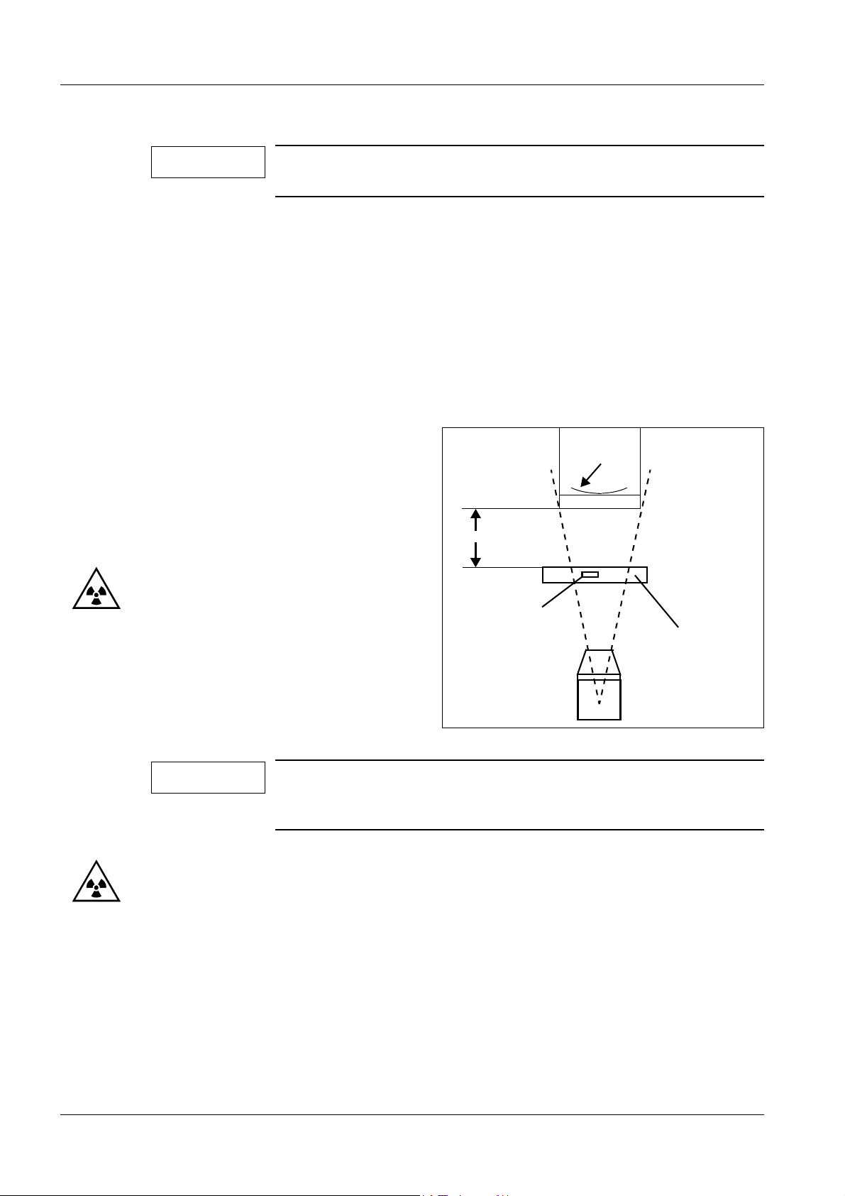
5 - 22 Adjustments / Programming
Setting the maximum skin dose rate 5
NOTE
Setting the maximum skin dose rate is only necessary for countries where DHHS regulations apply.
Prerequisites 5
• Program one of the FL curves S2, HC 2, HC 3, IOD or CAR and select it for the adjust-
ment.
• The X-ray tube cover must be fitted.
• Use the measuring chamber of the dose measuring device for dose rate measurement
>10 R/min.
• If an area dose product measuring device (DIAMENTOR) is present, it must be installed
above the radiation exit window of the POWERPHOS.
Preparations 5
• Attach the dose measuring chamber
at a distance of 30 cm (Fig. 3) from
the I.I. housing.
• Select one of the FL curves S 2,
HC 2, HC 3, IOD or CAR (according
to which is programmed).
30 cm
Input
screen
• Briefly release fluoro.
• Select kV Stop mode and enter
125 kV. The maximum tube current
is obtained automatically.
NOTE
If the maximum tube current was already reduced, the mA value
displayed at 125kV should be recorded and used for the calculation. The maximum skin dose rate should be set to 9R/min.
Fig. 3
Chamber
Bracket
POWERPHOS
Measurement 5
• Switch fluoroscopy on.
• Read and record the dose rate value displayed on the dose rate measuring device .
• If the measured value exceeds 9R/min, the maximum tube current must be reduced.
If the measured value is less than 9R/min, the tube current does not need to be reduced.
• Switch fluoroscopy off.
ARCOSKOP SPR2-250.840.01 Seite 22 von 42 Siemens AG
System Manual Rev. 01 09.05 CS PS 24 Medical Solutions
Page 55

Adjustments / Programming 5 - 23
• Calculate the maximum tube current
Tube current displayed in mA at 125 kV * 9 (R/min)
Dose rate value, measured in R/min
= tube current to be programmed
in mA
• Multiply the tube current to be programmed by 10, since this must be entered into the
service PC in 1/10 mA steps. Round off the value to the nearest whole number.
Example: Tube current displayed at 125 kV: 4.4 mA
Maximum skin dose rate: 9 R/min
Measured dose rate value: 11.2 R/min
4.4 (mA) * 9 (R/min)
11.2 (R/min)
= 3.53 (mA)
In 1/10 mA: 35.3, rounded off to the nearest whole
number: 35
The value to be programmed is 35
Programming 5
• Connect the service PC to the serial interface of the ARCOSKOP.
• Select the "Adjustment, Parameters..." menu.
• Select "Limitation of skin dose rate (FL)" in the "Parameter Groups" combo box.
• Click on "Get from unit".
• Enter the value to be programmed in "Value".
• Click on "Set Value".
• Select "Put to unit". Follow the menu guidance on the service PC.
• Select "Save to file".
• The value to be programmed has been transferred to the ARCOSKOP and temporarily
saved to disk.
NOTE
You must exit the service program with "Logoff" and "Quit".
Only then will the modified parameters be stored on the disk as a
new file!
Checking 5
• After programming, check the maximum skin dose rate again.
Siemens AG SPR2-250.840.01 Seite 23 von 42 ARCOSKOP
Medical Solutions Rev. 01 09.05 CS PS 24 System Manual
Page 56

5 - 24 Adjustments / Programming
Collimator, X-Iris 5
NOTE
WAR NING
The positions of the semitransparent slot diaphragms are dependent on the mechanics. Open the slot diaphragms to maximum
aperture before adjusting the X-Iris.
X-ray radiation!
See Chapter 1, Safety Information.
Use radiation protection! Wear a lead apron!
• Attach the centering cross to the center of the image intensifier input screen.
• Connect the service PC to the serial interface of the ARCOSKOP.
• Start the service program.
• Select the "Adjustment, Calibrations.." menu.
• Answer the query with "yes".
Start adjustment 5
• Select "X-Iris" in the "Function Groups" combo box.
• In the "Available Functions:" window select "Init (Limits Off / Autosearch)" and click on
"Execute".
• Close the status window by clicking on the OK button.
• For the query "Do you want to reset the Unit", click on "No".
• The X-Iris can now be completely opened and closed with the X-Iris keys.
Full format, X-Iris open 5
• Select I.I. full format.
• During fluoroscopy, adjust the X-Iris by opening and closing it with the X-Iris keys, so that
the blades are still visible along the edge of the I.I. screen.
• Select " II. - Full Format Position" on the service PC and click on "Execute".
• Close the status window by clicking on the OK button.
• For the query "Do you want to reset the Unit", click on "No".
Zoom format, X-Iris open 5
• Switch to zoom format.
• During fluoroscopy, adjust the X-Iris by opening and closing it with the X-Iris keys, so that
the blades are still visible along the edge of the I.I. screen.
• Select " II. - Zoom Format Position" on the service PC and click on "Execute".
• Close the status window by clicking on the OK button.
• For the query "Do you want to reset the Unit", click on "No".
ARCOSKOP SPR2-250.840.01 Seite 24 von 42 Siemens AG
System Manual Rev. 01 09.05 CS PS 24 Medical Solutions
Page 57

Adjustments / Programming 5 - 25
X-Iris minimum aperture 5
• Close the X-Iris completely.
• During fluoroscopy, adjust the X-Iris by opening and closing it with the X-Iris keys to a
diameter of < 4.5 cm; > 4 cm.
• Select "CLOSED POSITION" on the service PC and click on "Execute".
• Close the status window by clicking on the OK button.
• For the query "Do you want to reset the Unit", click on "No".
Save values and end adjustment 5
• Select "Init Off & Store Positions" on the service PC and click on "Execute".
• Close the status window by clicking on the OK button.
• For the query "Do you want to reset the Unit", click on "Yes".
• Switch the ARCOSKOP off and then on again.
Concluding tasks 5
• Check the X-Iris again in full format and zoom format. The blades must still be visible on
the edge of the image. If necessary, repeat the adjustment.
• Return to the main menu on the service PC with the ESC key.
• Before exiting the service program, save the new parameter values to disk
(Service PC, menu "Data Backup").
Collimator, slot diaphragm 5
NOTE
Prerequisites 5
• Camera rotation must be correctly adjusted.
• The image reversal functions must be disabled.
• Connect the service PC to the serial service interface.
• Start the service program.
• Select the "Adjustment, Calibrations..." menu.
• Respond to the query with "Yes".
With existing CARD collimator, the two blades of the slot diaphragm are shown on the monitor off-center.
• Mark the circle mask diameter in the upper left corner and lower right corner on the
screen of monitor A.
Siemens AG SPR2-250.840.01 Seite 25 von 42 ARCOSKOP
Medical Solutions Rev. 01 09.05 CS PS 24 System Manual
Page 58

5 - 26 Adjustments / Programming
Disable circle mask 5
• Select "Slot Diaphragm" in the "Function Groups:" combo box.
• In the "Available Functions:" window, select "Disable circle mask" and click on "Execute".
The circle mask in memory is switched off.
• Close the status window by clicking on the OK button.
• For the query "Do you want to reset the unit", click on "No".
Start adjustment 5
• Select "INIT (LIMITS OFF/ AUTOSEARCH)" in the "Available Functions:" window and
then click on "Execute".
• Close the status window by clicking on the OK button.
• For the query "Do you want to reset the unit", click on "No".
• The mechanical limits are checked and the position values are stored automatically.
• The camera rotation is automatically moved to the 0° position.
• The X-Iris is opened to max. aperture.
Slot diaphragm, 0° position 5
• Switch off zoom.
• Attach a centering cross or similar object to the I.I. in order to evaluate the position of the
fluoro image.
WAR NING
X-ray radiation!
See Chapter 1, Safety Information.
Use radiation protection! Wear a lead apron!
• Switch on fluoro and move the slot diaphragm to the 0° position using the slot diaphragm
rotation keys. The blades should be vertically positioned on the monitor screen.
• Switch off fluoro.
• In the "Available Functions:" window select "0 DEGREE POSITION" and click on
"Execute".
• Close the status window by clicking on the OK button.
• For the query "Do you want to reset the unit", click on "No".
Full format, slot diaphragm open 5
• The blades are automatically moved into the setting position (rotated approx. 45°).
• Switch on fluoro.
• Open the slot diaphragm until the two blades are located outside the marking of the circle
mask.
• Switch off fluoro.
ARCOSKOP SPR2-250.840.01 Seite 26 von 42 Siemens AG
System Manual Rev. 01 09.05 CS PS 24 Medical Solutions
Page 59

Adjustments / Programming 5 - 27
• In the "Available Functions:" window select "II.-FULL FORMAT POSITION" and click on
"Execute".
• Close the status window by clicking on the OK button.
• For the query "Do you want to reset the unit", click on "No".
Zoom format, slot diaphragm open 5
• The blades are automatically moved into the setting position (rotated approx. 45°).
• Select zoom format.
• Switch on fluoro.
• Open the slot diaphragm until the two blades are located outside the marking of the circle
mask.
• Switch off fluoro.
• In the "Available Functions:" window select "II.-ZOOM FORMAT POSITION" and click
on "Execute".
• Close the status window by clicking on the OK button.
• For the query "Do you want to reset the unit", click on "No".
Slot diaphragm closed 5
NOTE
Prerequisite:
During initialization (see paragraph Start adjustment), this value
is aready learned and stored. Setting can therefore be skipped.
Exception: On the customer's request the minimum spacing between the blades can be increased according to the following description.
• Perform the setting of the slot diaphragm as described above, including "Zoom format,
slot diaphragm open".
• Select zoom format.
• Switch on fluoro.
• Open slot diaphragm to customer's request.
• Switch off fluoro.
NOTE
The spacing between the blades must be smaller than for the setting "Zoom format, slot diaphragm open".
• Select "CLOSE POSITION" on the service PC.
• Close the status window by clicking on the OK button.
• For the query "Do you want to reset the unit" click on "No".
Siemens AG SPR2-250.840.01 Seite 27 von 42 ARCOSKOP
Medical Solutions Rev. 01 09.05 CS PS 24 System Manual
Page 60

5 - 28 Adjustments / Programming
Enable circle mask 5
• In the "Available Functions:" window select "Enable circle mask" and click on "Execute".
• Close the status window by clicking on the OK button.
• For the query "Do you want to reset the unit" click on "No".
Save values and end adjustment 5
• In the "Available Functions:" window select "INIT OFF & STORE POSITION" and click
on "Execute".
• For the query "Do you want to reset the unit", click on "Yes". The adjustment values are
stored.
Concluding tasks 5
• Switch the system off and then on again.
• Return to the main menu by pressing ESC on the service PC.
• Before exiting the service program, save the new parameter values to disk
(Service PC, Data menu, Backup).
Collimator display on the monitor 5
Prerequisites 5
• Camera rotation, collimators for X-Iris and slot diaphragm must be set correctly.
WAR NING
Collimator display, X-Iris 5
• Connect the service PC to the serial interface of the ARCOSKOP.
• Start the service program.
• Select the "Adjustment, Calibrations..." menu.
• Respond to the query with "Yes".
• Select "Screen Display XIRIS" in the "Function Groups:" combo box.
Start adjustment
• In the "Available Functions:" window select "Init" and click on "Execute". The X-Iris is
automatically opened to full format and the slot diaphragm is opened to maximum
aperture.
X-ray radiation!
See Chapter 1, Safety Information.
Use radiation protection! Wear a lead apron!
ARCOSKOP SPR2-250.840.01 Seite 28 von 42 Siemens AG
System Manual Rev. 01 09.05 CS PS 24 Medical Solutions
Page 61

Adjustments / Programming 5 - 29
Full format, X-Iris open
• Zoom must be disabled.
• Release fluoro and wait until the generator has performed automatic adjustment.
• Switch fluoro off. The X-Iris is displayed on the monitor.
• Use the keys for opening and closing the X-Iris to set the diameter of the superimposed
circle to the size of the X-iris.
• In the "Available Functions:" window select "Open Pos - II. Full Format" and click on
"Execute".
• Close the status window by clicking on the OK button.
• For the query "Do you want to reset the unit", click on "No". The X-Iris is automatically
closed to the smallest format.
Full format, X-Iris closed
• Briefly release fluoro. The X-Iris is displayed on the monitor.
• Use the keys for opening and closing the X-Iris to set the diameter of the superimposed
circle to the size of the X-Iris.
• In the "Available Functions:" window select "Close Pos - II. Full Format" and click on
"Execute".
• Close the status window by clicking on the OK button.
• For the query "Do you want to reset the unit", click on "No".
• The X-Iris remains in the minimum position.
• Zoom format is automatically selected.
Zoom format, X-Iris closed
• Briefly release fluoro. The X-Iris is displayed on the monitor.
• Use the keys for opening and closing the X-Iris to set the diameter of the superimposed
circle to the size of the X-Iris.
• In the "Available Functions:" window select "Close Pos - II. Zoom Format" and click on
"Execute".
• Close the status window by clicking on the OK button.
• For the query "Do you want to reset the unit" click on "No".
• The X-Iris is opened automatically.
• Zoom format remains selected.
Siemens AG SPR2-250.840.01 Seite 29 von 42 ARCOSKOP
Medical Solutions Rev. 01 09.05 CS PS 24 System Manual
Page 62

5 - 30 Adjustments / Programming
Zoom format, X-Iris open
• Briefly release fluoro. The X-Iris is displayed on the monitor.
• Use the keys for opening and closing the X-Iris to set the diameter of the superimposed
circle to the size of the X-Iris.
• In the "Available Functions:" window select "Open Pos - II. Zoom Format and click on
"Execute".
• Close the status window by clicking on the OK button.
• For the query "Do you want to reset the unit", click on "No".
Save values and end adjustment
• In the "Available Functions:" window select "INIT OFF & STORE VALUES" and click on
"Execute".
• Close the status window by clicking on the OK button.
• For the query "Do you want to reset the unit", click on "Yes".
Concluding tasks
Before ending the service program, save the new parameter values to disk
(Service PC, Data menu, Backup).
Collimator display, slot diaphragm 5
NOTE
NOTE
Prerequisites
With an existing CARD collimator, the two blades of the slot diaphragm are shown on the monitor off-center.
Setting the slot diaphragm display is performed with respect to
the visible front edge of the semitransparent slot diaphragm blades. With an existing CARD collimator, the slot diaphragm blades
are displayed approx. 25 mm further to the outside after the setting procedure. This ensures that, in the middle kV range, the displayed slot diaphragm blades mark the limit of the visible
shadowing in the fluoroscopic image more or less.
• The setting of the camera rotation is correctly adjusted and is in the 0° position.
• With existing CARD collimator, the parameter "OFFSET" (see "Adjustments...,
Parameters..., SLOT DIAPHRAGM SCREEN DISPLAY") must be set to the value 50.
With existing standard collimator, the parameter "OFFSET" must be set to the value 0.
• Mark the circle mask diameter in the upper left corner and lower right corner on the
screen of monitor A.
• Connect the service PC to the serial interface of the ARCOSKOP.
• Start the service program.
• Select the "Adjustments, Calibrations..." menu. Answer the query with "Yes".
• Select "SCREEN DISPLAY SLOT DIAPHRAGM" in the "Function Groups:" combo box.
ARCOSKOP SPR2-250.840.01 Seite 30 von 42 Siemens AG
System Manual Rev. 01 09.05 CS PS 24 Medical Solutions
Page 63

Adjustments / Programming 5 - 31
Disable circle mask
• Switch off zoom.
• In the "Available Functions:" window, select "DISABLE CIRCLE MASK" and click on
"Execute". Close the status window by clicking on the OK button.
For the query "Do you want to reset the Unit", click on "No".
Start adjustment
• In the "Available Functions:" window select "INIT" and click on "Execute". Close the
status window by clicking on the OK button.
For the query "Do you want to reset the Unit", click on "No".
Full format, slot diaphragm open
• Move the camera to the 0° position.
➪ The X-Iris opens automatically and can be opened further with the keys for ope-
ning the X-Iris.
➪ The slot diaphragm moves automatically to the default position for full format
(rotated approx. 45°).
• Release fluoro briefly.
• Open and close the slot diaphragm display using the control keys.
• Set the line shown on the monitor so that it coincides with the front edge of the lower right
blade.
• In the "Available Functions:" window select "OPEN POS - II. FULL FORMAT" and click
on "Execute". Close the status window by clicking on the OK button.
For the query "Do you want to reset the Unit", click on "No".
Full format, right slot diaphragm closed
• The slot diaphragm closes automatically.
• Release fluoro briefly.
• Open and close the slot diaphragm display using the control keys.
• Set the line shown on the monitor so that it coincides with the front edge of the lower right
blade.
• In the "Available Functions:" window select "RIGHT POS. II. - FULL FORMAT" and click
on "Execute". Close the status window by clicking on the OK button.
For the query "Do you want to reset the Unit", click on "No".
Siemens AG SPR2-250.840.01 Seite 31 von 42 ARCOSKOP
Medical Solutions Rev. 01 09.05 CS PS 24 System Manual
Page 64

5 - 32 Adjustments / Programming
Full format, left slot diaphragm closed
• The slot diaphragm remains closed.
• Release fluoro briefly.
• Open and close the slot diaphragm display using the control keys.
• Set the line shown on the monitor so that it coincides with the front edge of the upper left
blade.
• In the "Available Functions:" window select "LEFT POS. II - FULL FORMAT" and click on
"Execute". Close the status window by clicking on the OK button.
For the query "Do you want to reset the Unit", click on "No".
Zoom format, slot diaphragm closed
• Release fluoro briefly.
• Open and close the slot diaphragm display with the control keys.
• Set the line shown on the monitor so that it coincides with the front edge of the lower right
blade.
• In the "Available Functions:" window select "CLOSE POS - II. ZOOM FORMAT" and
click on "Execute". Close the status window by clicking on the OK button.
For the query "Do you want to reset the Unit", click on "No".
➪ The slot diaphragm opens automatically and should still be visible in the corners
of the image.
Zoom format, slot diaphragm open
• Release fluoro briefly.
• Open and close the slot diaphragm display with the control keys.
• Set the line shown on the monitor so that it coincides with the front edge of the lower right
blade.
• In the "Available Functions:" window select "OPEN POS - II. ZOOM FORMAT" and click
on "Execute". Close the status window by clicking on the OK button.
For the query "Do you want to reset the Unit", click on "No".
Enable circle mask
• In the "Available Functions:" window select "Enable Circle Mask" and click on "Execute".
Close the status window by clicking on the OK button.
For the query "Do you want to reset the unit", click on "No".
Save values and end adjustment
• In the "Available Functions:" window select "INIT OFF & STORE VALUES" and click on
"Execute". Close the status window by clicking on the "OK" button.
For the query "Do you want to reset the Unit", click on "Yes".
ARCOSKOP SPR2-250.840.01 Seite 32 von 42 Siemens AG
System Manual Rev. 01 09.05 CS PS 24 Medical Solutions
Page 65

Adjustments / Programming 5 - 33
Concluding tasks
• Before exiting the service program, save the new parameter values to disk
(Service PC, Data menu, Backup).
• Remove the markings of the circle mask diameter again.
Siemens AG SPR2-250.840.01 Seite 33 von 42 ARCOSKOP
Medical Solutions Rev. 01 09.05 CS PS 24 System Manual
Page 66

5 - 34 Adjustments / Programming
Left side of the patient
Right side of the patient
Fig. 4
Fig. 5 Fig. 6
Camera rotation 5
WAR NING
NOTE
NOTE
X-ray radiation!
See Chapter 1, Safety Information.
Use radiation protection! Wear a lead apron!
The position of the VIDEOMED DC to the camera rotation mechanism must be set correct.
See Chapter 6 "Replacing the VIDEOMED DC, Camera rotation 0°
position".
Before adjusting the camera rotation, the keys for horizontal and
vertical image reversal must be off. Camera rotation should be set
to the 0° position. Fig. 4, Fig. 5 and Fig. 6 shows the 0° position.
ARCOSKOP SPR2-250.840.01 Seite 34 von 42 Siemens AG
System Manual Rev. 01 09.05 CS PS 24 Medical Solutions
Page 67

Adjustments / Programming 5 - 35
NOTE
With the right camera rotation key (arrow on key pointing clockwise) the marker superimposed on the monitor will rotate clockwise, but the image contents will rotate counterclockwise.
With the left camera rotation key (arrow on key pointing counterclockwise) the marker superimposed on the monitor will rotate
counterclockwise, but the image contents will rotate clockwise.
• Connect the service PC to the serial interface of the ARCOSKOP.
• Start the service program.
• Select the "Adjustment, Calibrations..." menu.
• Answer the query with "Yes".
Start adjustment
• Select "Camera Rotation" in the "Function Groups:" combo box.
• In the "Available Functions:" window select "Init (Disable Limits)" and click on "Execute".
• Close the status window by clicking on the OK button.
• For the query "Do you want to reset the Unit", click on "No".
• Mount a piece of wire and an Allen key to the I.I. input screen as shown in Fig. 5.
Fig. 6 shows the corresponding fluoro image at 0 degree camera rotation position.
Camera rotation +180° position
• Switch on fluoro and rotate the camera to the + 180° position with the clockwise camera
rotation key. The image contents will rotate counterclockwise.
• Switch off fluoro. In the "Available Functions:"
window select "+180 Degree Position" and click on "Execute".
• Close the status window by clicking on the OK button.
• For the query "Do you want to reset the Unit" click on "No".
Camera rotation 0° position
• Switch on fluoro and rotate the camera to the 0° position. The image (left/right / up/down)
will correspond to Fig. 6.
• Switch off fluoro. In the "Available Functions:"
window select "0 Degree Position" and click on "Execute".
• Close the status window by clicking on the OK button.
• For the query "Do you want to reset the Unit" click on "No".
Siemens AG SPR2-250.840.01 Seite 35 von 42 ARCOSKOP
Medical Solutions Rev. 01 09.05 CS PS 24 System Manual
Page 68

5 - 36 Adjustments / Programming
Camera rotation -180° position
• Switch on fluoro and rotate the camera to the -180° position (with the counterclockwise
camera rotation key). The image contents will rotate clockwise.
• Switch off fluoro. In the "Available Functions:"
window select "-180 Degree Position" and click on "Execute".
• Close the status window by clicking on the OK button.
• For the query "Do you want to reset the Unit", click on "No".
Save values and end adjustment
• In the "Available Functions:" window select "Init Off & Store Positions" and click on
"Execute".
• Close the status window by clicking on the OK button.
• For the query "Do you want to reset the Unit" click on "Yes".
• Return to the service program main menu using the ESC key.
Concluding tasks
• Before exiting the service program, save the new parameter values to disk
(Service PC, Data menu, Backup).
ARCOSKOP SPR2-250.840.01 Seite 36 von 42 Siemens AG
System Manual Rev. 01 09.05 CS PS 24 Medical Solutions
Page 69

Adjustments / Programming 5 - 37
Potentiometer
Fig. 7
Calibrating the area dose product measuring device 5
NOTE
CONSTANT parameters = T
• Read and record the T
measuring device (see Fig. 7).
This adjustment is used to calibrate the area dose product
measuring device to the ARCOSKOP display.
w
value shown on the electronics unit of the area dose product
w
Programming 5
• Connect the service PC to the serial interface of the ARCOSKOP.
• Start the service program.
• Select the "Adjustment, Parameter..." menu.
• Select "Diamentor" in the "Parameter Groups" combo box.
• Click on "Get from Unit".
• The parameter "1. Diamentor Existing" must be on YES.
• Select parameter "2. Constant T
• Enter the parameter T
in the "Value Actual:" field.
w
.
w
• Click on "Set Value".
5
• Click on "Put to Unit".
• Click on "Save to File".
NOTE
Siemens AG SPR2-250.840.01 Seite 37 von 42 ARCOSKOP
Medical Solutions Rev. 01 09.05 CS PS 24 System Manual
You must exit the service program with "Logoff" and "Quit" in
order to save the modified parameters to disk as a new file.
Page 70

5 - 38 Adjustments / Programming
Potentiometer
Fig. 8
Checking the programmed value 5
NOTE
Prerequisites
• The T
value is already programmed (see Programming).
w
Checking the programmed values will activate the self-test in the
electronics unit of the area dose product measuring device.
This serves to recalibrate the electronics unit.
• Connect the service PC to the serial interface of the ARCOSKOP.
• Start the service program.
• Select the "Adjustment, Calibrations..." menu.
• Answer the query with "Yes".
• Select "Diamentor" in the "Function Group:" combo box.
• In the "Available Functions" window select the line "Start Diamentor Test" and click on
"Execute".
• Close the status window by clicking on the OK button.
• Respond to the query "Do you want to reset the unit" by clicking "No".
• Press the >0< key (reset key for fluoroscopy time). The current value is displayed on the
monitor.
• The tested T
• This value must match the programmed CONSTANT parameter T
value is displayed on the monitor of the ARCOSKOP.
w
. Tolerance: ± 5 %.
w
• If the ->0<- key is pressed (reset key for fluoroscopic time) the test is repeated and is
displayed again on the monitor.
• The potentiometer (Fig. 8) of the area dose product measuring device can be used to
adjust the test value
T
to the programmed value Tw .
w
• After the adjustment, select "Stop Diamentor Test" on the service PC and click on
"Execute".
• Close the status window by clicking on the OK button.
• Respond to the query "Do you want to reset the unit" by clicking "No".
ARCOSKOP SPR2-250.840.01 Seite 38 von 42 Siemens AG
System Manual Rev. 01 09.05 CS PS 24 Medical Solutions
Page 71

Adjustments / Programming 5 - 39
• The test is concluded. Check the accuracy of the area dose product measuring device
(see next page).
Checking the accuracy of the area dose product measuring device
Prerequisites 5
The calibration of the measuring device must already have been performed.
The X-Iris is correctly set; the blades are still just visible on the monitor screen.
Preparations 5
• Attach the centering cross in the center of the I.I. (Fig. 9).
• Select I.I. zoom format.
• Select kV-mA-curve plateau IOD.
• Attach the small (1 cm
3
) dose measuring chamber in the center of the I.I. (Fig. 10).
5
NOTE
The radiation field must cover the entire area of the dose measuring chamber. If necessary, center the dose measuring chamber
on the I.I. again.
• Release fluoroscopy briefly, adjusting the X-iris on the radiation field to a format of
approximately 8 cm.
• Do not make any further adjustments to the X-Iris.
• Record the inner diameter (key width, Fig. 11) of the octagonal area of the radiation field.
• Remove the centering cross.
• The measuring chamber is still in the center of the I.I. .
Dose measurement 5
• Press the "Next Pat" key to reset the area dose product display on the ARCOSKOP
monitor to 0.
• Select kV STOP and set manual to 70 kV.
• Reset the dose measuring device (Dali, Nomex ...) to 0.
• Release fluoroscopy for approx. 20 seconds (~ 3mGy). The measured dose K
be high enough that the selected measurement range of the dose measuring device
(Dali, Nomex...) is fully utilized; if necessary, reset the area dose product display on the
ARCOSKOP and the dose measuring device and repeat the measurement with a
different fluoroscopic time (Check these selections again: I.I. zoom format, kV-Stop,
70 kV).
should
E
• Record the measured dose K
.
E
• Record the area dose product FDPa displayed on the ARCOSKOP.
Calculating the area dose product 5
• To calculate the measured area dose product: (measured area dose product FDPg) =
(measured dose K
Siemens AG SPR2-250.840.01 Seite 39 von 42 ARCOSKOP
Medical Solutions Rev. 01 09.05 CS PS 24 System Manual
) * (inner diameter d)2 * 0.829.
E
Page 72

5 - 40 Adjustments / Programming
POWERPHOS
Centering cross
RBV / I.I.
Fig. 9 Fig. 10
POWERPHOS
Measuring chamber
RBV / I.I.
Fig. 11
Evaluation 5
Calculate the deviation between the measured area dose product FDPg and the displayed
area dose product FDPa:
The deviation must be < 0.3.
Deviation = [(displayed area dose product FDPa) - (measured area dose product FDPg)] /
(measured area dose product FDPg).
For deviations > 0.3, the area dose product measuring device must be replaced.
ARCOSKOP SPR2-250.840.01 Seite 40 von 42 Siemens AG
System Manual Rev. 01 09.05 CS PS 24 Medical Solutions
Page 73

Adjustments / Programming 5 - 41
Overview of ARCOSKOP parameters 5
• Call up the "Moreinfo.hlp" help file on the service PC for a short description of the para-
meters available on the ARCOSKOP.
NOTE
If parameters have been changed and saved in the "Adjustments,
Parameter" menu with Save to file, you must exit the service program with "Logoff" and "Quit" in order to save the modified parameters to disk.
Overview of MEMOSKOP Fast parameters 5
• The "CDATA.HLP" help file contains a short description of the respective parameters.
The Operating Instructions describe the parameters that can be accessed by the
customer.
Cable module 5
• Check the auxiliary voltages at test points TP1= +15 V, TP2= 0V GND,
TP3= -15 V, LED D4 lights up. 24 V at plug ST1.1= +24 V and ST1.2= 0V.
(Tolerance: 22.8 V to 29.5 V).
Holding force after orbital movement of C-arm 5
• Voltage at TP6 approx. 9 - 13 V. Adjustable with potentiometer P1.
Sensor 5
• Move C-arm to horizontal position, with control unit on top.
• Switch off orbital brake.
• Move C-arm approx. 10 cm in clockwise direction.
• LED D3 lights up at half intensity at TP4 1 V ± 0.1 V. Adjustable by loosening and rotating
the sensor. Following adjustment tighten down lock nut again.
LED D6 motor fault 5
• If LED D6 lights up, the motor is then not enabled.
Possible causes: Short circuit or break in sensor, logic control defective.
Siemens AG SPR2-250.840.01 Seite 41 von 42 ARCOSKOP
Medical Solutions Rev. 01 09.05 CS PS 24 System Manual
Page 74

5 - 42 Adjustments / Programming
This page intentionally left blank.
ARCOSKOP SPR2-250.840.01 Seite 42 von 42 Siemens AG
System Manual Rev. 01 09.05 CS PS 24 Medical Solutions
Page 75

Replacing boards / Replacing components 6
6 - 1
WAR NING
NOTE
X-ray radiation!
See Chapter 1, Safety Information.
Observe the safety instructions!
In particular the general safety and accident prevention regulations must be observed.
The installation locations of the boards/components are described in Chapter 1 under "Service position of the board slide-in
module of the electronics box" and under Chapter 3 under "Low
voltages".
Control board D1 6
NOTE
Replacement and additional work 6
• Loosen all plug connections to board D1.
If possible, read out the load counter values and store them on
disk. In the case of a tube replacement, return the current load
counter data as well as the load counter data stored on failure of
board D1 along with the defective POWERPHOS.
NOTE
The board D1 is delivered as a spare part with the basic configuration stored in the GAL J32. If J32 is not replaced by the module
on the defective board, the possibly enabled options of the
system are no longer available!
Remove the IC with the designation J32 from the old board D1
and plug it on the new board D1 in the base J32.
• Replace board D1. Pay attention to the insulating disks.
• Plug back all connection cables. Pay attention to the correct location of the shields and
ground wires.
• Plug in or switch the jumpers and switches according to the wiring diagram.
Especially check that the jumpers X95, X96 and X99 are inserted in position 2-3.
• Disable the FIFO at the service PC, serial port (COM1 or COM2).
• Perform the download of control board D1.
• After download wait approximately 1 min. and wait for booting.
NOTE
After replacing the board D1, the heat values stored in the NVRAM
will not be initialized. Therefore, the temperature indicator lights
up and the KV/mA display is flashing. The heat unit counter is
decreasing the values automatically during the next few minutes;
then, the unit is ready for the necessary adjustments.
To accelerate the process, you can reset the heat counter, which
makes the unit ready for immediate use.
Siemens AG SPR2-250.840.01 Seite 1 von 32 ARCOSKOP
Medical Solutions Rev. 01 09.05 CS PS 24 System Manual
Page 76

6 - 2 Replacing boards / Replacing components
Resetting the heat values after replacing board D1 6
• Select the "Adjustments..." menu.
• Select the "Calibrations..." submenu.
• Answer the question with "yes".
• Select "Reset Tube Values" in the "Function Groups:" combo box.
• Select "Heat Value" and click the "OK" button.
• Answer the question "Do you want to reset the Unit?" with "yes".
• After restart, the unit is ready for use.
Transferring the parameter 6
• Transfer the parameters of the system to board D1.
- Select "DATA" menu, "RESTORE" parameter and click Restore.
• Check the dose rate and adjust if necessary.
• Check the function of the camera rotation and adjust if necessary.
• Check the function of the collimator and adjust if necessary.
• Check the function of the collimator displays on the monitor and adjust if necessary.
• Check the function of the area dose product measuring device (if present).
• Check the FL / PFL / DCM / DR functions.
ARCOSKOP SPR2-250.840.01 Seite 2 von 32 Siemens AG
System Manual Rev. 01 09.05 CS PS 24 Medical Solutions
Page 77

Replacing boards / Replacing components 6 - 3
Interface board D30 6
WAR NING
Electrical voltage!
See Chapter 1, Safety Information.
Observe the safety instructions!
In particular the general safety and accident prevention regulations must be observed.
Switch the system free of voltage to replace the PC board.
• Replace the interface board D30.
• Check the +27 V /+24 V /+24 V voltages, adjust if necessary (see Chapter 3 of these
instructions "Checking the operating voltages"). Check the radiation release / format
switch-over / vertical column travel / brake functions.
Board D40 6
• Remove the covers on the horizontal beam, see Chapter 1 under "Covers".
• After replacing the boards, check and, if necessary, adjust the voltage corresponding to
Chapter 3 under "Low voltages".
Board D41/42 6
• On replacing the board D41/42 observe the coding in Chapter 3 under D41/ D42
"Programming".
Generator, D21 including MCB2 6
WAR NING
• Bring the board slide-in module into the service position as described in Chapter 1 under
"Service position of the board slide-in module of the electronics box".
• Loosen all plug and screw connections to the D21.
• Replace the D21. Pay attention to the insulating disks.
• Reestablish the plug and screw connections. Pay attention to the correct location and
contact of the shields and ground wires.
• Perform generator download. After the download, switch the system off and on again.
Electrical voltage!
See Chapter 1, Safety Information.
Observe the safety instructions!
In particular the general safety and accident prevention regulations must be observed.
To replace the PC board switch the system free of voltage.
• Perform generator learning and mAs adjustment.
• Perform the IQ quick test.
Siemens AG SPR2-250.840.01 Seite 3 von 32 ARCOSKOP
Medical Solutions Rev. 01 09.05 CS PS 24 System Manual
Page 78

6 - 4 Replacing boards / Replacing components
Power supply unit D20 6
WAR NING
Electrical voltage!
See Chapter 1, Safety Information.
Switch the system free of voltage.
Wait until the LED's V147 and LED F3-F8 have gone out.
For safety purposes, check the voltage at test points U
after discharge of the Elko batteries. The voltage must be < 20 V.
and Uz+
z-
• Measure the ZW voltage. The voltage must be < 20 V.
• Unscrew the lateral plastic covers.
• Loosen all plug and screw connections.
• Remove board D20 including cooling plate.
• Install the new board D20 including cooling plate.
• Assembly and installation of the unit is performed in the reverse order.
• Tighten the cable connections X7 to X11 with a torque of 4.8 Nm.
• Perform a visual inspection. Pay attention to the correct location and contact of the
shields and ground wires. Especially the plug connection X5 and X6 on D115.
• Perform generator learning.
• Check the FL / PFL / DCM / DR functions.
Starting unit D115 6
WAR NING
• Measure the ZW voltage. The voltage must be < 20 V.
• Unscrew the lateral plastic covers.
• Loosen all plug and screw connections.
• Remove board D115.
• Apply heat conduction paste under the power module.
• Install the new board D115.
• Assembly and installation of the unit is performed in the reverse order.
• Perform a visual inspection. Pay attention to the correct location and contact of the
shields and ground wires. Especially the plug connection X5 and X6 on D115.
Electrical voltage!
See Chapter 1, Safety Information.
Switch the system free of voltage.
Wait until the LED's V147 and LED F3-F8 have gone out.
For safety purposes, check the voltage at test points U
after discharge of the Elko batteries. The voltage must be < 20 V.
and Uz+
z-
• Check the FL / PFL / DCM / DR functions.
ARCOSKOP SPR2-250.840.01 Seite 4 von 32 Siemens AG
System Manual Rev. 01 09.05 CS PS 24 Medical Solutions
Page 79

Replacing boards / Replacing components 6 - 5
Generator Elko buffer modules 6
WAR NING
Electrical voltage!
See Chapter 1, Safety Information.
Switch the system free of voltage.
Wait until the LED's V147 and LED F3-F8 have gone out.
For safety purposes, check the voltage at test points U
after discharge of the Elko batteries. The voltage must be < 20 V.
• Measure the ZW voltage. The voltage must be < 20 V.
• Replace the defective Elko buffer module.
• Check the FL / PFL / DCM / DR functions.
and Uz+
z-
Siemens AG SPR2-250.840.01 Seite 5 von 32 ARCOSKOP
Medical Solutions Rev. 01 09.05 CS PS 24 System Manual
Page 80

6 - 6 Replacing boards / Replacing components
5
4
2
1
3
1
4
2
3
6
1
6
Fig. 1
Fig. 2
1
5
2
1
4
2
4
3
POWERPHOS 6
Removing the POWERPHOS 6
• Remove the single-tank cover.
• Before the replacement, note the height of all nutating screws (3/Fig. 1 and 4/Fig. 1).
• If present, remove the dose measuring chamber.
- Remove the insulating plate of the measuring chamber.
• Remove the collimator.
• Remove the bracket with fan.
• Loosen the fastening screws (1/Fig. 1) of the POWERPHOS.
ARCOSKOP SPR2-250.840.01 Seite 6 von 32 Siemens AG
System Manual Rev. 01 09.05 CS PS 24 Medical Solutions
Page 81

Replacing boards / Replacing components 6 - 7
• To remove the two front cable clips (6/Fig. 1), the front spacing screws can be turned to
maximum distance between the single-tank holder and the C-arm.
• Loosen all plug and screw connections of the cable connections.
• Remove and set down the POWERPHOS.
- Cable ties of minimum strength, type 30 x 6 mm (Fig. 2) can be used for this.
- Guide cable ties through the front and the two rear holes of the fastening screws.
• Remove the spacer (5/Fig. 1) and attach it to the new POWERPHOS.
• Unscrew the nutating screws (3/Fig. 1) and screw them into the new POWERPHOS.
Installing the POWERPHOS 6
CAUTION
Danger of injury!
In the case of non-compliance slight to medium injury can occur
due to crushing fingers.
Caution when inserting the POWERPHOS in the C-arm!
• Bring the new POWERPHOS into the C-arm. Pay attention to cables and your fingers.
• Attach the collimator.
• If present, attach the dose measuring chamber.
• Install the bracket with fan.
• Connect all cables and plugs and fit the cable clips.
NOTE
The cables must not be crushed.
• On the basic unit, pull out the connector D21.X3 from board D21.
With an ohmmeter measure from all leads of the connector X3
(cable side) to the protective ground wire.
There must be no connection to the protective ground wire!
• Tighten the cable connections X7 and X9 with a torque of 4.8 Nm.
• Pay attention to perfect cable running of all cables and clamping the shields.
• Set the nutating screws (3/Fig. 1 and 4/Fig. 1) to the distances noted at the start.
• Screw in the fastening screws (1/Fig. 1), but do not tighten them but leave a few
millimeters distance to the housing.
• Switch on the ARCOSKOP.
• Check the function of the two fans.
- The visible fan must turn.
- The fan installed in the C-arm must run audibly. The visible fan can be stopped
mechanically for a short time for this.
WAR NING
Siemens AG SPR2-250.840.01 Seite 7 von 32 ARCOSKOP
Medical Solutions Rev. 01 09.05 CS PS 24 System Manual
X-ray radiation!
See Chapter 1, Safety Information.
Do not work without radiation protection! Wear a lead apron!
Page 82

6 - 8 Replacing boards / Replacing components
• Unscrew the nutating screws (4/Fig. 1) slightly so that the POWERPHOS can be
centered with the nutating screws (3/Fig. 1).
• Perform generator learning and mAs adjustment.
• Fluoroscopy on.
Set the collimator opening on the monitor so that all sides are just visible.
• Fluoroscopy off.
• Determine the direction in which the POWERPHOS must be aligned.
No image reversal: The collimator sides appear on the monitor above- left side,
below- right side, on the left- front side, on the right- rear side.
• By setting the nutating screws (3/Fig. 1) on the POWERPHOS, adjust the collimator
centrally on the monitor.
• After each adjustment, release fluoro briefly to display the change on the monitor (LIH).
• Set the nutating screws (4/Fig. 1) on the C-arm.
• After the collimator has been centered, uniformly tighten the fastening screws. Take care
that the radiation field does not migrate again.
• Switch on fluoroscopy briefly and check the collimator position.
• The blades of the X-Iris must be visible on all sides of the monitor image in fluoroscopy in
the full format and zoom format at maximum opening.
• Check and, if necessary, adjust the X-Iris and slot diaphragm positions (in the full format
and zoom format).
• Check the function of the area dose product measuring device (if present).
• For countries working with DHHS regulations, check and, if necessary, adjust the
maximum skin dose.
• A 2nd set of identification labels of the POWERPHOS is affixed to the basic unit.
Remove the old identification labels of the collimator and glue the supplied labels at the
same place.
The original labels of the POWERPHOS must agree with the glued-on labels.
Fans 6
Visible fan:
• Remove single-tank cover.
• Replace the visible fan.
- Pay attention to the direction of rotation - airflow in the direction of the single-tank.
Fan installed in the C-arm:
• Removing the POWERPHOS:
Proceed analogously to Chapter 6 "POWERPHOS, Removing the POWERPHOS".
• Replace the fan installed in the C-arm. Pay attention to the direction of rotation.
• Airflow in the direction of POWERPHOS.
• Installing the POWERPHOS and checking the fans:
Proceed analogously to Chapter 6 "POWERPHOS, Installing the POWERPHOS".
ARCOSKOP SPR2-250.840.01 Seite 8 von 32 Siemens AG
System Manual Rev. 01 09.05 CS PS 24 Medical Solutions
Page 83

Replacing boards / Replacing components 6 - 9
Collimator 6
• Replace the collimator.
• Check the function and setting of the collimator, readjust if necessary,
(see Chapter 5 "X-Iris collimator and slot diaphragm").
• The blades of the X-Iris must be visible on all side of the monitor image in fluoroscopy in
the full format and zoom format.
• Check the collimator displays on the monitor and readjust if necessary
(see Chapter 5 "Collimator display on the monitor").
• A 2nd set of identification labels of the collimator is affixed to the basic unit. Remove the
old labels of the collimator and glue the supplied labels at the same place.
The original labels of the collimator must agree with the glued-on labels.
Diamentor 6
• Remove the single-tank cover.
• Replace the Diamentor.
• Check the function of the Diamentor.
• Perform adjustment of the area dose product measuring device (see under Chapter 5).
• Check the accuracy of the area dose product measuring device (see under Chapter 5).
Replacement of the I.I. 6
Checking the temperature indicator 6
• Before attaching the I.I. check the temperature indicators of the I.I.:
• If the inner square field of the indicator shows white, there is no excess temperature,
then remove the temperature indicator.
• If there is coloration of the indicator (inner field black), proceed according to IQ document
RXD-000.038.01...
WAR NING
Electrical voltage!
See Chapter 1, Safety Information.
Switch off the ARCOSKOP and wait approx. 3 minutes so that the
high voltages on the I.I. minivoltage supply decay.
Siemens AG SPR2-250.840.01 Seite 9 von 32 ARCOSKOP
Medical Solutions Rev. 01 09.05 CS PS 24 System Manual
Page 84

6 - 10 Replacing boards / Replacing components
Dismantling 6
CAUTION
VIDEOMED DC
Danger of injury!
In the case of non-compliance slight to medium physical injury
and/or damage to property can arise.
The C-arm cover contains counterbalance weights and weighs
> 10 kg.
Hold the covers firmly when removing / installing them.
Before removing the C-arm cover, move the C-arm into its middle
orbital position.
After removing the C-arm cover, do not move the C-arm into its
orbital end positions (I.I. in the orbital end position).
• Move the I.I. into the service position (see Chapter 1 "I.I. service position").
• Remove the VIDEOMED DC and place it on a dustfree surface.
• Cover it to prevent contamination (see Chapter 6 "VIDEOMED DC").
I.I. minivoltage supply
• Remove the I.I. minivoltage supply and place it down on a suitable surface (control unit
and high-voltage power supply).
• See "Replacing the I.I. minivoltage supply".
• Dissipate any residual charge in the cables by shorting them to ground.
• Remove the O-ring and the cap nut from the anode cable.
• Remove the plug for the cassette contact.
• Disconnect all cables (protective wire, cable to VIDEOMED DC etc....) from the I.I.
• At the same time remove the cable ties or the cable clips.
• Draw all the cables inside the C-arm.
I.I. and Compact optics
NOTE
When removing the Compact optics, make sure that no dust or
dirt drops onto the output window of the I.I.
Do not loosen the eccentric screws (2/Fig. 8) on the edge of the
Compact optics!
These screws are used to center the Compact optics to the I.I.
output screen.
• Lift the I.I. a little alternately on each side and retighten the nuts.
Repeat this until the I.I. is fastened again. Be careful not to damage the cables.
• Tighten the nuts to fasten the I.I. again.
• Move the C-arm so that the POWERPHOS is above and the I.I. is below (angulation).
• Remove the two threaded rods (service pack) from the I.I. housing.
ARCOSKOP SPR2-250.840.01 Seite 10 von 32 Siemens AG
System Manual Rev. 01 09.05 CS PS 24 Medical Solutions
Page 85

Replacing boards / Replacing components 6 - 11
• Lift the I.I. up out from the C-arm, turn it around and place it on a suitable surface
(I.I. is standing on the grid.)
• Remove the clips for attaching the plugs and cable guide from the I.I.
• Remove the Compact optics and place them on a dustfree surface.
• Reattach the Compact optics and clips to the new I.I.
• Remove the grid. Unsolder the wires for the cassette contact.
Installation 6
Compact optics
NOTE
When installing the Compact optics and the VIDEOMED DC, make
sure that no dust drops on the output window of the I.I. or on the
Compact optics.
• Reattach the Compact optics to the new I.I.
• When doing this, guide the anode wire through the recess in the optics.
• The camera optics must lie against the eccentric screws.
• Reinstall the O-ring and the cap nut for the anode cable.
• The cable length should be 70 mm from the beginning of the white wire to the cap nut.
• Reattach the clips for attaching the plug and the cable guide to the I.I.
Image intensifier
• Set the I.I. back on the C-arm flange. The labels should face the C-arm.
• Turn the threaded rods (service pack) back in the I.I. threaded holes at least 5 turns.
• Then mount the spacers and nuts.
• Tighten the nuts to fasten the I.I.
• Turn the C-arm so that the I.I. is above and the POWERPHOS is below (angulation).
• Lower the I.I. by gradually loosening the nuts alternately. Be careful not to damage the
cables.
I.I. minivoltage supply
• Reinstall the high-voltage power supply of the I.I. minivoltage supply.
• Reconnect the control unit but do not tighten the screws at this point.
• Route the cables to the high-voltage power supply and the control unit and secure them
with cable ties or cable clips.
Siemens AG SPR2-250.840.01 Seite 11 von 32 ARCOSKOP
Medical Solutions Rev. 01 09.05 CS PS 24 System Manual
Page 86

6 - 12 Replacing boards / Replacing components
VIDEOMED DC
• Turn the camera rotation of the Compact optics into the 0° position (slowly!) (see also
Chapter 6 "Replacing the VIDEOMED DC").
• Connect an ohmmeter to the potentiometer for camera rotation, point 2 and 3.
There should be a resistance of 5000 ohms ± 40 ohms at 0°. See also notes on page
6-14.
• Place the VIDEOMED DC in the 0° position on the Compact optics and clamp it securely.
Checks and adjustments
• Check and adjust the electrode voltages of the I.I. according to the test protocol of the I.I.
• Check the resolution, if necessary adjust the optical sharpness of the Compact optics.
• Use the IQ quick test, Chapter "Resolution for evaluating the optical sharpness" for this
purpose.
• Check and, if necessary, adjust the dose rate.
• Check that the camera optics are centered onto the I.I. output screen and, if necessary,
adjust them. (Refer also to "Replacing the Compact optics", paragraph "Checking the
centering of the camera optics to the I.I. output screen" and "Centering the Compact
optics to the I.I. output screen").
• Check the camera rotation and, if necessary, adjust it (range of rotation + 220°).
Concluding work
• Reinstall the I.I. on the C-arm flange (see Chapter 1 "I.I. service position").
• Check the collimator display on the monitor and adjust it if necessary.
• Perform the IQ quick test.
• Perform the country-specific acceptance tests (§16 Partial acceptance test, DHHS,...).
ARCOSKOP SPR2-250.840.01 Seite 12 von 32 Siemens AG
System Manual Rev. 01 09.05 CS PS 24 Medical Solutions
Page 87
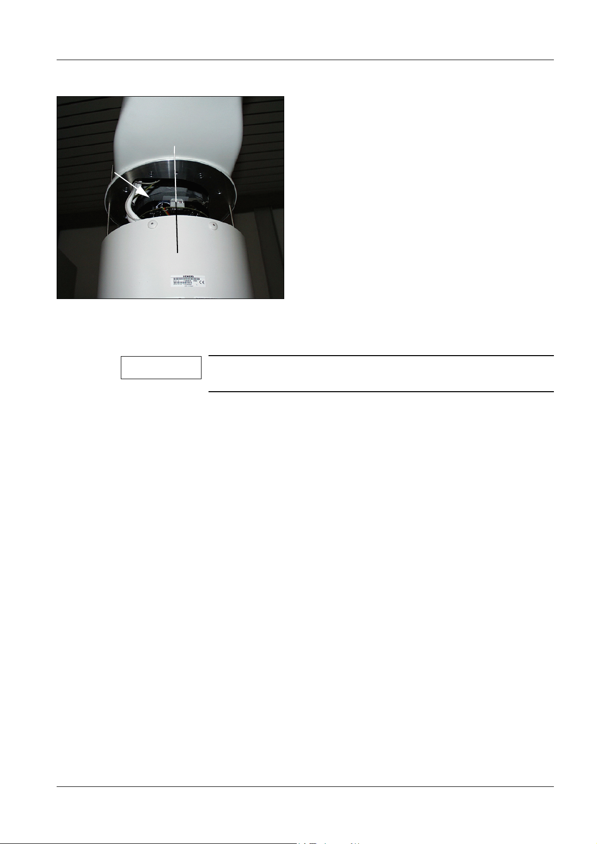
Replacing boards / Replacing components 6 - 13
0° Position
Fig. 3
Replacing the VIDEOMED DC 6
NOTE
When removing or installing the VIDEOMED DC, ensure that the
optics are free of dust or dirt particles.
• Move the I.I. into the service position (see Chapter 1 "I.I. Service position").
• Remove the cable ties on the VIDEOMED DC board (see arrow/ Fig. 3).
• Loosen the plug connection between VIDEOMED DC and the Compact optics.
• Unlock the plug of the cable drum and pull it out.
• Remove the locking screw of the VIDEOMED DC.
• Remove the VIDEOMED DC.
Siemens AG SPR2-250.840.01 Seite 13 von 32 ARCOSKOP
Medical Solutions Rev. 01 09.05 CS PS 24 System Manual
Page 88

6 - 14 Replacing boards / Replacing components
Camera rotation 0° position 6
• Connect an ohmmeter to the actual value potentiometer of the Compact optics at
point 2 and 3.
NOTE
If the numbering of the connections on the actual value potentiometer is not legible, this can be determined with the ohmmeter.
Prerequisite:
• All connection cables from the camera optics to board D1 are
plugged in.
• Connect a wire of the ohmmeter to the housing or protective
ground wire.
• With the 2nd wire of the ohmmeter determine the ground
connection of the actual value potentiometer:
- Measured value: < 20 ohms; = Potentiometer Pin 3.
• Turn the Compact optics on the clamping ring approximately
into the mechanical mid position (slowly!).
• With the 2nd wire of the ohmmeter determine the middle
connection of the potentiometer:
• Measured value ~3000 to ~7000 ohms, according to accuracy of
the mid position; = Potentiometer Pin 2.
• It is still possible to measure at the 3rd connection of the poten-
tiometer as a check:
- Measured value: 10000 ohms ± 5 %; = Potentiometer Pin 1.
• Then connect the measuring wires of the ohmmeter to the
potentiometer Pin 2 and Pin 3.
• Turn the Compact optics on the clamping ring (slowly!) until the ohmmeter indicates
5000 ohms ± 40 ohms (0° position). Do not adjust the camera rotation any more.
• Set and clamp the new VIDEOMED DC in the 0° position. The center of the plug is
exactly in the center of the I.I. housing in the 0° position (see Fig. 3).
• Plug back the plug of the cable drum.
• Plug back the connection between VIDEOMED DC and Compact optics and fix with
cable ties. Take care that the cable or the cable tie do not project beyond the edge of the
board and lie in the recess of the VIDEOMED DC board.
• Still leave the I.I. in the service position.
Checks and adjustments 6
• Switch on the system and turn the camera rotation from + 220° to -220°.
In this case the cable of the cable drum must permit the complete rotation range and
must not drop laterally out from the cable drum.
• Lift the I.I. a little alternately on each side and retighten the nuts.
Repeat this until the I.I. is fastened again. Be careful not to damage the cables.
• Tighten the nuts to fasten the I.I.
ARCOSKOP SPR2-250.840.01 Seite 14 von 32 Siemens AG
System Manual Rev. 01 09.05 CS PS 24 Medical Solutions
Page 89

Replacing boards / Replacing components 6 - 15
• Check the camera rotation and adjust if necessary. It should be possible to turn the
camera 220° + 3° or -220° -3° (check by reference to the indicator).
• Move the C-arm so that the POWERPHOS is above and the I.I. is below (angulation).
• Remove the two threaded rods (service pack) again from the threaded holes of the I.I.
and reinstall the I.I. with the two attachment screws.
• Check and, if necessary, readjust the dose rate.
• Perform the IQ quick test. Firstly check the resolution. If necessary, readjust the optical
sharpness on the Compact optics (see under "Settings - optical sharpness").
I.I. minivoltage supply 6
WAR NING
CAUTION
NOTE
Electrical voltage!
See Chapter 1, Safety Information.
Before removing the high-voltage power supply the system must
be switched off for > 3 minutes so that the high voltages on the I.I.
minivoltage supply decay.
Danger of injury!
In the case of non-compliance slight to medium physical injury
and/or damage to property can arise.
The C-arm cover contains counterbalance weights and weighs
> 10 kg.
Hold the covers firmly when installing or removing them.
Before loosening the C-arm cover, move the C-arm into its middle
orbital position.
After loosening the C-arm cover, do not move the C-arm into its
orbital end positions (I.I. in orbital end position).
Rotate the camera into the 0° position prior to starting work to
avoid having to readjust the camera rotation.
NOTE
Siemens AG SPR2-250.840.01 Seite 15 von 32 ARCOSKOP
Medical Solutions Rev. 01 09.05 CS PS 24 System Manual
The cathode wire of the I.I. (black wire connected to plug CON1.8
on the control unit) is sometimes very short.
The cathode wire can be extended for easier access to the test
points and potentiometer on the control unit. To extend the wire,
split the wire and strip off the insulation from the wire ends.
Place 2 pieces of shrink tubing of suitable diameter over the wire
ends. Solder an approx. 25 cm wire of 0.75 mm².
Insulate the wire ends with shrink tubing.
Page 90

6 - 16 Replacing boards / Replacing components
Fig. 4 Fig. 5
Fig. 6
• Remove the cover on the front of the C-arm by removing the screws (I.I. side, see Fig. 4).
• Move the I.I. into the service position (see Chapter 1 "I.I. service position").
• Remove both attachment screws for the control unit in the I.I. flange of the C-arm
(see arrow/ Fig. 5).
• Carefully remove the control unit from the C-arm and disconnect all plugs.
• Disconnect the protective ground wire connection.
• Remove the VIDEOMED DC camera from the I.I.
• See "Replacing board / Replacing components VIDEOMED DC".
• Remove both attachment screws for the high-voltage power supply from the I.I. flange of
the C-arm (Fig. 6).
• Remove the high-voltage power supply from the C-arm.
• Disconnect all the plugs. Dissipate any residual charge in the cables by shorting them to
ground.
ARCOSKOP SPR2-250.840.01 Seite 16 von 32 Siemens AG
System Manual Rev. 01 09.05 CS PS 24 Medical Solutions
Page 91

Replacing boards / Replacing components 6 - 17
• Install the new high-voltage power supply.
• Connect the control unit but tighten the screws only after adjustment
(see "Adjusting the I.I. minivoltage supply").
• Refit and clamp the VIDEOMED DC.
Adjusting the I.I. minivoltage supply 6
CAUTION
NOTE
Danger of injury!
In the case of non-compliance slight to medium physical injury
and/or damage to property can arise.
The C-arm cover contains counterbalance weights and weighs
> 10 kg. Hold the covers firmly when installing or removing them.
Before loosening the C-arm cover, move the C-arm into its middle
orbital position. After loosening the C-arm cover, do not move the
C-arm into its orbital end positions (I.I. in orbital end position).
The cathode wire of the I.I. (black wire connected to plug CON1.8
on the control unit) is sometimes very short.
The cathode wire can be extended for easier access to the test
points and potentiometer on the control unit. To extend the wire,
split the wire and strip off the insulation from the wire ends.
Place 2 pieces of shrink tubing of suitable diameter over the wire
ends. Solder an approx. 25 cm wire of 0.75 mm². Insulate the wire
ends with shrink tubing.
• Hold the covers firmly when removing or installing them!
• Remove the cover from the front of the C-arm by removing the screws (I.I. side).
• Move the I.I. into the service position (see Section "I.I. service position").
• Loosen the two fastening screws of the control unit on the I.I. flange of the C-arm.
• Carefully remove the control unit from the C-arm.
• Adjust the voltages E1 (test point UE1), E2 (test point UE2), E3 (test point UI15) and
anode (test point UI30) according to the I.I. protocol, see also wiring diagram.
• Reinstall the control unit in the C-arm.
• Reinstall the cover of the C-arm.
• Perform the IQ quick test.
• Check the function and setting of the collimator and adjust if necessary.
• Check the function and setting of the monitor collimator display, adjust if necessary.
• Check the 0° position of the camera rotation (see "Replacing the VIDEOMED DC, 0°
position").
• Check the camera rotation function.
• Lift the I.I. a little alternately on each side and retighten the nuts.
Repeat this until the I.I. is fastened again. Be careful not to damage the cables.
Siemens AG SPR2-250.840.01 Seite 17 von 32 ARCOSKOP
Medical Solutions Rev. 01 09.05 CS PS 24 System Manual
Page 92

6 - 18 Replacing boards / Replacing components
• Tighten the nuts to fasten the I.I.
• Check the camera rotation function (range of rotation + 220°).
• Move the C-arm so that the POWERPHOS is above and the I.I. is below (angulation).
• Remove the two threaded rods (service pack) again from the threaded holes of the I.I.
and reinstall the I.I. with the two attachment screws.
ARCOSKOP SPR2-250.840.01 Seite 18 von 32 Siemens AG
System Manual Rev. 01 09.05 CS PS 24 Medical Solutions
Page 93

Replacing boards / Replacing components 6 - 19
0° Position
Fig. 7
Replacing the Compact optics 6
WAR NING
Electrical voltage!
See Chapter 1, Safety Information.
Switch off the ARCOSKOP and wait approx. 3 minutes so that the
high voltages on the I.I. minivoltage supply decay.
Dismantling 6
CAUTION
Camera optics
Danger of injury!
In the case of non-compliance slight to medium physical injury
and/or damage to property can arise.
The C-arm cover contains counterbalance weights and weighs
> 10 kg.
Hold the covers firmly when installing or removing them.
Before loosening the C-arm cover move the C-arm into its middle
orbital position.
After loosening the C-arm cover, do not move the C-arm into its
orbital end positions (I.I. or POWERPHOS in the orbital end position).
• Bring the I.I. into the service position (see Chapter 1 "I.I. service position").
• Turn the camera into the 0° position (see Fig. 7).
VIDEOMED DC
• Cut open the cable tie (see arrow/Fig. 7) and disconnect the plugs.
• Remove plug X1 on the Compact optics.
• Remove the VIDEOMED DC and place it down protected from dust (see also
"Replacing the VIDEOMED DC").
Siemens AG SPR2-250.840.01 Seite 19 von 32 ARCOSKOP
Medical Solutions Rev. 01 09.05 CS PS 24 System Manual
Page 94

6 - 20 Replacing boards / Replacing components
5
3
1
2
3
2
Fig. 8
4
High-voltage power supply of the I.I. minivoltage supply
• Remove the high-voltage power supply of the I.I. minivoltage supply. Loosen the two
fastening screws on the C-arm flange (see arrows/ Fig. 7).
• Disconnect the anode cable from the high-voltage power supply and withdraw the O-ring
and the cap nut from the cable.
Compact optics
NOTE
When removing the Compact optics make sure that no dust or dirt
drops on the output window of the I.I.
Do not loosen the eccentric screws (2/Fig. 8) on the edge of the
Compact optics!
These screws are used to center the Compact optics to the I.I.
output screen.
• Loosen the fastening screws of the Compact optics. If necessary, also remove the clip
for the plugs / cable routing and remove the Compact optics.
Installation
NOTE
When installing the Compact optics make sure that no dust or dirt
drops on the output window of the I.I. or on the Compact optics.
Optics
• Reinsert the rubber gasket between the Compact optics and the I.I. housing.
• Reinstall the new Compact optics. Reattach the clip for the plugs / cable routing.
• To do so, run the anode cable through the recess in the Compact optics.
• The Compact optics must lie against the eccentric screws.
ARCOSKOP SPR2-250.840.01 Seite 20 von 32 Siemens AG
System Manual Rev. 01 09.05 CS PS 24 Medical Solutions
Page 95

Replacing boards / Replacing components 6 - 21
High-voltage power supply
• Reinstall the O-ring and the cap nut on the anode cable. The cable length from the
beginning of the white wire to the cap nut should be 70 mm.
• Reconnect the high-voltage cable.
• Reinstall the high-voltage power supply.
Reattach the cables for the high-voltage power supply with cable ties.
Camera rotation 0° position
• Rotate the camera rotation of the Compact optics into 0° position.
• Connect an ohmmeter to the potentiometer for camera rotation, point 2 and 3.
• In the 0° position, the resistance must be 5000 ohms ± 40 ohms.
• If necessary, hold the Compact optics by the clamping ring for the VIDEOMED DC and
slowly rotate them.
VIDEOMED DC
• Place and clamp the Videomed DC in the 0° position on the Compact optics (see also
Fig. 7).
• Plug back the connection cable (see arrow/ Fig. 7) and fasten the cable with a cable tie in
the recess of the VIDEOMED DC board. When doing this, make sure that the cable tie
and the cable do not project over the edge of the board.
• Reconnect plug X1 of the VIDEOMED DC cable drum.
Other cables
• Reconnect all cables and plugs and fasten them with cable ties.
Settings 6
Optical sharpness
• The I.I. remains in the service position.
WAR NING
X-ray radiation!
See Chapter 1, Safety Information.
Observe radiation protection! Wear a lead apron!
• Fasten the sharpness test to the I.I. input.
• Attach 2.1 mm Cu + 60 mm Al to the radiation exit of the POWERPHOS.
• Use the IQ quick test, Chapter "Resolution for evaluating the optical sharpness".
• Check the optical sharpness and, if necessary, adjust on the wider ring of the optics.
If necessary, loosen the long screw on the upper narrow ring with a suitable hexagonal
key (contained in the "Service Pack I.I./ Camera". See Chapter 1 "I.I. Service position").
Siemens AG SPR2-250.840.01 Seite 21 von 32 ARCOSKOP
Medical Solutions Rev. 01 09.05 CS PS 24 System Manual
Page 96

6 - 22 Replacing boards / Replacing components
Fig. 9
Checking the camera optics centering at the I.I. output screen
WAR NING
X-ray radiation!
See Chapter 1, Safety Information.
Observe radiation protection! Wear a lead apron!
• Mark the center of the image intensifier at the I.I. input accurately and fasten a small
washer <
3.2 mm by means of adhesive tape. Select full format.
• Move the camera rotation into the 0° position.
• Switch on fluoroscopy briefly.
• Mark the center of the washer or of the lead cross on the monitor (see Fig. 9).
• Turn the camera into the -220° position.
• Mark the center again on the monitor (see Fig. 9).
• Turn the camera into the +220° position.
• Mark the center again on the monitor (see Fig. 9).
• Place an 8 mm washer over the three markings. All three markings must be located
within the 8 mm diameter of the washer.
An 8 mm washer has a somewhat larger inside diameter of 8.4 mm, therefore the
markings must clearly lie within the inside diameter and should not touch the edge of the
washer.
• With a diameter < 8 mm, the following centering adjustment does not have to be
performed. Continue with "Checks and adjustments".
• If the markings go beyond > 8 mm proceed as described in "Centering the camera optics
on the I.I. output screen".
ARCOSKOP SPR2-250.840.01 Seite 22 von 32 Siemens AG
System Manual Rev. 01 09.05 CS PS 24 Medical Solutions
Page 97

Replacing boards / Replacing components 6 - 23
Centering the camera optics to the I.I. output screen
WAR NING
Prerequisite: The marking of the +220°, -220° and 0° positions was already performed as
previously described.
X-ray radiation!
See Chapter 1, Safety Information.
Observe radiation protection! Wear a lead apron!
• Rotate the camera optics back to the 0° position.
• Slightly loosen the three fastening screws of the camera optics.
• Slightly loosen both eccentric screws adjacent to the camera optics.
• Move the camera optics towards the center, between the two +220° and -220° markings
(see also Fig. 9).
• Switch on fluoroscopy briefly and evaluate the position shift on the monitor.
Due to the ratio of the I.I. input screen diameter to the I.I. output screen diameter, a shift
of the camera optics by 0.1 mm corresponds to a position shift of the washer displayed
on the monitor of more than 1.7 mm (23 cm I.I.).
• Fasten the camera optics again.
• Wipe off the three markings on the monitor.
• Switch fluoroscopy on briefly and mark the new 0° position.
• Turn the camera into the -220° position.
• Mark the center again on the monitor.
• Turn the camera into the + 220° position.
• Mark the center again on the monitor.
• Place an 8 mm washer over the three markings. All three markings must be located
within the 8 mm diameter of the washer.
An 8 mm washer has a somewhat larger inside diameter of 8.4 mm, therefore the
markings must clearly lie within the inside diameter and should not touch the edge of the
washer.
• If necessary, repeat the adjustment until the three markings are within the 8 mm
diameter.
• Tighten the camera optics.
• Set and tighten the eccentric screws against the camera optics.
Checks and adjustments
• Lift the I.I. a little alternately on each side and retighten the nuts.
Repeat this until the I.I. is fastened again. Be careful not to damage the cables.
• Tighten the nuts to fasten the I.I.
• Check and, if necessary, readjust the camera rotation (range of rotation + 220°).
• Check and, if necessary, readjust the setting of the X-Iris.
• Check and, if necessary, readjust the collimator displays on the monitor.
Siemens AG SPR2-250.840.01 Seite 23 von 32 ARCOSKOP
Medical Solutions Rev. 01 09.05 CS PS 24 System Manual
Page 98

6 - 24 Replacing boards / Replacing components
• Move the C-arm so that the POWERPHOS is above and the I.I. is below (angulation).
• Remove the two threaded rods (service pack) again from the threaded holes of the I.I.
and reinstall the I.I. with the two attachment screws.
• Check and if necessary readjust the dose rate.
• Perform the IQ quick test.
Basic unit control panel 6
• Location of the board, Chapter 3 "Low voltages".
• Disconnect the plug X3 for the control panel from board D42.
• Remove the cable clip of the cable to the control panel.
• Remove the Allen screws on the fastening ring (swivel joint of the control panel).
• Replace the control panel.
• Reinstall the fastening ring.
• Reconnect the cable.
• Reattach the cable clip.
• Perform a functional test of the control panel.
Foot switch 6
• When replacing the standard foot switch with the combination version (a/Fig. 10), install
the new foot switch holder (x/Fig. 11) with 2 screws and washers.
x
a
Fig. 10 Fig. 11
• When replacing the standard foot switch with the combination version and vice versa
perform the wiring corresponding to the following table.
• When removing the cover from the cross beam make sure that the paint is not scratched.
ARCOSKOP SPR2-250.840.01 Seite 24 von 32 Siemens AG
System Manual Rev. 01 09.05 CS PS 24 Medical Solutions
Page 99

Replacing boards / Replacing components 6 - 25
Fig. 12 Foot switch
• Run the cable through the opening and fasten it with the braid to the clamp, see Fig. 10.
• Insert the pins according to the following list in the X4 STANDARD or X5 GASTRO
connector provided.
Siemens AG SPR2-250.840.01 Seite 25 von 32 ARCOSKOP
Medical Solutions Rev. 01 09.05 CS PS 24 System Manual
Page 100

6 - 26 Replacing boards / Replacing components
• View from the wire connection side
• STANDARD:
- 1 - blue
- 2 - black
- 3 - --
-4 - brown
-5 - white
- 6 - --
• GASTRO:
-1 - brown
- 2 - red
- 3 - --
-4 - yellow
-5 - green
- 6 - --
-7 - white
- 8 - black
-9 - grey
- 10 - violet
- 11 - blue
• Run the cable with connector from below through the lifting column to board D40.
• Plug the connector to board D40.X4 Standard or X5 Gastro.
• Fasten the covers onto the support again.
ARCOSKOP SPR2-250.840.01 Seite 26 von 32 Siemens AG
System Manual Rev. 01 09.05 CS PS 24 Medical Solutions
 Loading...