

Page 1

Mühlhäuser
I I Laser Targeting Device
Installation and Startup
Option
SP
Installation and Start-up
Valid for:
SIREMOBIL 2000 / Compact / ISO C / ISO C 3D
POWERMOBIL
ARCOKOP
ARCADIS systems
Print No.:
Replaces:RXR2-120.814.01.02.02
RXR2-120.814.01.02.02
© Siemens AG
The reproduction, transmission or use
of this document or its contents is not
permitted without express written
authority. Offenders will be liable for
damages. All rights, including rights
created by patent grant or registration
of a utility model or design, are
reserved.
English
Doc. Gen. Date: 01.05
2003
Page 2

2 Revision / Disclaimer
1Revision / Disclaimer
Document revision level
The document corresponds to the version/revision level effective at the time of system
delivery. Revisions to hardcopy documentation are not automatically distributed.
Please contact your local Siemens office to order current revision levels.
Disclaimer
The installation and service of equipment described herein is to be performed by qualified
personnel who are employed by Siemens or one of its affiliates or who are otherwise
authorized by Siemens or one of its affiliates to provide such services.
Assemblers and other persons who are not employed by or otherwise directly affiliated
with or authorized by Siemens or one of its affiliates are directed to contact one of the
local offices of Siemens or one of its affiliates before attempting installation or service procedures.
I I Laser Targeting Device RXR2-120.814.01.02.02 Siemens AG
01.05 CS SD 24
Page 2 of 16
Medical Solutions
Page 3

Table of Contents 3
1- 0Table of Contents
1 _______ General ________________________________________________________ 4
Required parts . . . . . . . . . . . . . . . . . . . . . . . . . . . . . . . . . . . . . . . . . . . . . . . . . . . . . . . . . 4
Required aids . . . . . . . . . . . . . . . . . . . . . . . . . . . . . . . . . . . . . . . . . . . . . . . . . . . . . . . 4
Configurations. . . . . . . . . . . . . . . . . . . . . . . . . . . . . . . . . . . . . . . . . . . . . . . . . . . . . . . 4
2 _______ Installation and Settings __________________________________________ 5
Installing the I.I. tension band. . . . . . . . . . . . . . . . . . . . . . . . . . . . . . . . . . . . . . . . . . . . . . 5
Adjusting the laser diodes to the I.I. size . . . . . . . . . . . . . . . . . . . . . . . . . . . . . . . . . . . . . 6
Checking the settings. . . . . . . . . . . . . . . . . . . . . . . . . . . . . . . . . . . . . . . . . . . . . . . . . . . . 7
Affixing the labels for the U.S.A.. . . . . . . . . . . . . . . . . . . . . . . . . . . . . . . . . . . . . . . . . . . . 8
Affixing the labels for the rest of the world . . . . . . . . . . . . . . . . . . . . . . . . . . . . . . . . . . . . 9
Functional check. . . . . . . . . . . . . . . . . . . . . . . . . . . . . . . . . . . . . . . . . . . . . . . . . . . . . . . 10
Final steps . . . . . . . . . . . . . . . . . . . . . . . . . . . . . . . . . . . . . . . . . . . . . . . . . . . . . . . . . . . 11
3 _______ Maintenance___________________________________________________ 12
Mechanical safety. . . . . . . . . . . . . . . . . . . . . . . . . . . . . . . . . . . . . . . . . . . . . . . . . . . . . . 12
Checking the operating values. . . . . . . . . . . . . . . . . . . . . . . . . . . . . . . . . . . . . . . . . . . . 13
4 _______ Service _______________________________________________________ 14
Replacing the laser diodes. . . . . . . . . . . . . . . . . . . . . . . . . . . . . . . . . . . . . . . . . . . . . . . 14
Functional checks. . . . . . . . . . . . . . . . . . . . . . . . . . . . . . . . . . . . . . . . . . . . . . . . . . . . . . 15
5 _______ Changes to previous version _____________________________________ 16
Siemens AG RXR2-120.814.01.02.02 I I Laser Targeting Device
Medical Solutions
01.05 CS SD 24
Page 3 of 16
Page 4

4 General
1General
2-
Required parts 0
NOTE
These instructions apply both to annual maintenance and replacement of laser diodes. See chapter 2, Maintenance, and chapter 3,
Service.
• I.I. laser light localizer 30 99 988:
- I.I. laser light localizer
- Tension band for 17 cm (7“), 23 cm (9“), 27 cm (11“) I.I. and 23 cm I.I. in combination
with 3D Navigation
- Labels
- Set of batteries
Required aids 0
• Toolbox (including set of Allen keys)
Configurations 0
• The I.I. laser light localizer is available as an add-on for:
- SIREMOBIL 2000 with 23 cm (9‘‘) I.I.
- SIREMOBIL Compact with 23 cm (9‘‘) I.I.
with 17 cm (7‘‘) I.I.
- SIREMOBIL Iso-C with 23 cm (9‘‘) I.I.
with 27 cm (11‘‘) I.I.
- SIREMOBIL Iso-C 3D with 23 cm (9") I.I. in combination
with 3D Navigation
- POWERMOBIL with 23 cm (9") I.I.
- ARCOSKOP with 23 cm (9") I.I.
- ARCADIS systems with 23 cm (9") I.I.
I I Laser Targeting Device RXR2-120.814.01.02.02 Siemens AG
01.05 CS SD 24
Page 4 of 16
Medical Solutions
Page 5
Installation and Settings 5
2Installation and Settings
3-
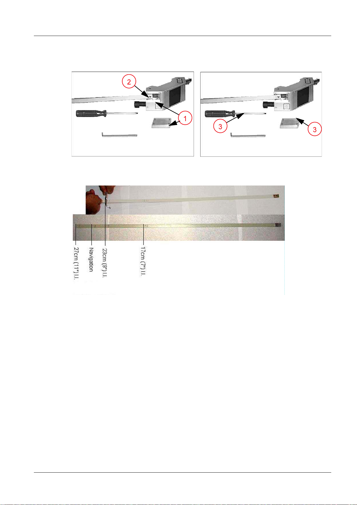
Installing the I.I. tension band 0
Fig. 1: I.I. tension band Fig. 2: I.I. tension band
Fig. 3: Fracture points
• Remove the cover (1/Fig.1/p.5) over the tension band.
• Remove the screw (2/Fig.1/p.5).
• The tension band fits for the 27 cm I.I. For other I.I. sizes, the tension band has to be
shortened at the marked fracture point. Apply flat pliers to the marked fracture point
and bend several times until the band breaks ((Fig.3/p.5) shows procedure for 23 cm
I.I.).
• Secure the tension band using the screw (2/Fig.1/p.5); secure screw with Loctite.
• Replace the cover (1/Fig.1/p.5).
Siemens AG RXR2-120.814.01.02.02 I I Laser Targeting Device
Medical Solutions
01.05 CS SD 24
Page 5 of 16
Page 6

6 Installation and Settings
Adjusting the laser diodes to the I.I. size 0
• Loosen the clamping screws (3/Fig.2/p.5) using the Allen key.
• Adjust the laser diodes to the I.I. size by pulling out or pushing in. There are 3 notice-
able catches.
• For 17 cm (7“) I.I.: Push in laser diodes until they lock into inside catch.
• For 23 cm (9“) I.I. without 3D Navigation: Pull out laser diodes until they lock into center
catch.
• For 27 cm (11“) I.I. and 23 cm (9") I.I. with 3D Navigation: Pull out laser diodes until they
lock into outside catch. Replace position plates (Fig.3/p.5) with the position plates de-
livered.
• Retighten the two clamping screws.
I I Laser Targeting Device RXR2-120.814.01.02.02 Siemens AG
01.05 CS SD 24
Page 6 of 16
Medical Solutions
Page 7

Installation and Settings 7
Checking the settings 0
• Install the batteries in the battery compartment according to the operating instructions.
• Install the I.I. laser light localizer on the I.I. according to the operating instructions. En-
sure that it is seated properly.
• Switch on the I.I. laser light localizer and align both laser beams with the tube focus.
Turn both thumb wheels at the front side of the laser diodes (also see operating instructions).
• Move the C-arm into all end positions and check again if the laser beams can be aligned
with the tube focus in every position.
NOTE
If the laser beams cannot be aligned with the tube focus in every
C-arm position, you have to repeat the adjustment of the laser diodes to the I.I. size and the subsequent check of the settings.
Siemens AG RXR2-120.814.01.02.02 I I Laser Targeting Device
Medical Solutions
01.05 CS SD 24
Page 7 of 16
Page 8

8 Installation and Settings
Affixing the labels for the U.S.A. 0
Fig. 4: Affixing labels for the U.S.A.
• Affix labels (8/Fig.4/p.8) and (9/Fig.4/p.8).
• Labels (6/Fig.4/p.8) and (7/Fig.4/p.8) are already affixed.
I I Laser Targeting Device RXR2-120.814.01.02.02 Siemens AG
01.05 CS SD 24
Page 8 of 16
Medical Solutions
Page 9

Installation and Settings 9
Affixing the labels for the rest of the world 0
Fig. 5: Affixing labels for the rest of the world
• Affix labels (13/Fig. 5 / p. 9) to the locations indicated.
• Affix label (14/Fig. 5 / p. 9) in the local language.
• Labels (10/Fig. 5 / p. 9) and (11/Fig. 5 / p. 9) are already affixed.
• For Great Britain only: Also affix labels (12/Fig. 5 / p. 9).
Siemens AG RXR2-120.814.01.02.02 I I Laser Targeting Device
Medical Solutions
01.05 CS SD 24
Page 9 of 16
Page 10

10 Installation and Settings
Functional check 0
• Check the function of the two keys to switch the laser light localizer on and off.
• Switch the laser light localizer back on. The laser beams must go off automatically after
approx. one minute.
I I Laser Targeting Device RXR2-120.814.01.02.02 Siemens AG
01.05 CS SD 24
Page 10 of 16
Medical Solutions
Page 11

Installation and Settings 11
Final steps 0
• File these instructions in Register 8, Service, in the system binder.
Siemens AG RXR2-120.814.01.02.02 I I Laser Targeting Device
Medical Solutions
01.05 CS SD 24
Page 11 of 16
Page 12

12 Maintenance
3Maintenance
4-
Mechanical safety 0
• Check the labeling of the laser light localizer according to (Fig.4/p.8) or (Fig.5/p.9)
of chapter 2.
• Replace damaged labels.
• Ensure that the I.I. laser light localizer is seated properly on the I.I. Pay special atten-
tion to the tension band and the tension band closure.
• Check the I.I. ring for damage.
• Check the laser aperture for soiling and damage.
• Check the alignment of the laser beams with the tube focus. It must be possible to align
the laser beams with the tube focus in all C-arm positions.
• Ensure that the batteries and the battery compartment are in good condition. Check for
residue from battery acid and oxidation inside the battery compartment.
I I Laser Targeting Device RXR2-120.814.01.02.02 Siemens AG
01.05 CS SD 24
Page 12 of 16
Medical Solutions
Page 13

Maintenance 13
Checking the operating values 0
• Check the function of the two keys to switch the laser light localizer on and off.
• Switch the laser light localizer back on. The laser beams must go off automatically af-
ter approx. one minute.
Siemens AG RXR2-120.814.01.02.02 I I Laser Targeting Device
Medical Solutions
01.05 CS SD 24
Page 13 of 16
Page 14

14 Service
4Service
5-
Replacing the laser diodes 0
Fig. 6: Replacing the laser diodes
• Remove the batteries from the battery compartment.
• Unscrew the battery compartment (1/Fig.6/p.14).
• Disconnect the cable of the defective laser diode (2/Fig.6/p.14).
• Loosen the clamping screw of the defective laser diode (3/Fig.6/p.14).
• Pull the laser diode out of the housing (4/Fig.6/p.14).
• Insert the new laser diode into the housing (cable side first).
• Connect the cable.
• Replace the battery compartment.
• Insert the batteries into the battery compartment and close the compartment.
• Push in the laser diode until it catches. See also "Adjusting the laser diodes to the I.I.
size“ in this document.
• Retighten the two clamping screws.
• Install the I.I. laser light localizer on the I.I. according to the operating instructions. En-
sure that it is seated properly.
• Switch on the I.I. laser light localizer and align both laser beams with the tube focus.
Turn both thumb wheels at the front side of the laser diodes (also see operating instructions).
• Move the C-arm into all end positions and check again if the laser beams can be aligned
with the tube focus in every position.
NOTE
If the laser beams cannot be aligned with the tube focus in every
C-arm position, you have to repeat the adjustment of the laser diodes to the I.I. size and the subsequent check of the settings.
I I Laser Targeting Device RXR2-120.814.01.02.02 Siemens AG
01.05 CS SD 24
Page 14 of 16
Medical Solutions
Page 15

Service 15
Functional checks 0
• Check the function of the two keys to switch the laser light localizer on and off.
• Switch the laser light localizer back on. The laser beams must go off automatically af-
ter approx. one minute.
• Also check the labeling.
Siemens AG RXR2-120.814.01.02.02 I I Laser Targeting Device
Medical Solutions
01.05 CS SD 24
Page 15 of 16
Page 16

16 Changes to previous version
5Changes to previous version
6-
Cover sheet changed
I I Laser Targeting Device RXR2-120.814.01.02.02 Siemens AG
01.05 CS SD 24
Page 16 of 16
Medical Solutions
 Loading...