

Page 1

Op
Opeeeen
OpOp
TTTTrrrran
AAAAPPPPOG
125-2189 Rev. 1, 9/98
n PPPPrrrroooocccceeeesso
n n
ane
e Dr
Drive
anan
e e
OGEE
EE CCCCoooommmmppppaaaattttiiiibbbblllleeee
OGOG
EE EE
iver O
DrDr
iveive
ssor
ssosso
r Own
r Or O
r w
with
r r
ww
wneeeerrrr’s
wnwn
ith
ithith
’s M
’s ’s
Manua
anuallll
MM
anuaanua
Page 2

Open Processor with Trane Driver Owner’s Manual
Rev. 1.0, December 1998
NOTICE
The information contained within this document is subject to change without notice and should not be construed as
a commitment by Siemens Building Technologies, Inc. Siemens Building Technologies, Inc. assumes no
responsibility for any errors that may appear in this document.
All software described in this document is furnished under a license and may be used or copied only in accordance
with the terms of such license.
WARNING
This equipment generates, uses, and can radiate radio frequency energy and if not installed and used in accordance
with the instructions manual, may cause interference to radio communications. It has been tested and found to
comply with the limits for a Class A digital device, pursuant to Part 15 of the FCC rules. These limits are designed to
provide reasonable protection against such interference when operated in a commercial environment. Operation of
this equipment in a residential area is likely to cause interference in which case users at their own expense will be
required to take whatever measures may be required to correct the interference.
SERVICE STATEMENT
Control devices are combined to make a system. Each control device is mechanical in nature and all mechanical
components must be regularly serviced to optimize their operation. All Landis & Staefa, Inc. branch offices and
authorized distributors offer Technical Support Programs that will ensure your continuous, trouble-free system
performance.
For further information, contact your nearest Siemens Building Technologies, Inc. representative.
Copyright 1998 by Siemens Building Technologies, Inc.
TO THE READER
A Reader Comment form is located at the end of this manual. Please use this form for reporting errors or
discrepancies.
APOGEE is a trademark of Siemens Building Technologies, Inc.
Tracer Summit is a trademark of The Trane Company
BACnet is a trademark of American Society of Heating, Refrigeration and Air Conditioning Engineers (ASHRAE)
Insight for Minicomputers is a registered trademark of Siemens Building Technologies, Inc.
Insight for Personal Computers is a registered trademark of Siemens Building Technologies, Inc.
Printed in U.S.A.
ii
Page 3

Table of Contents
TTTTaaaabbbblllle
e oooof
e e
How To Use This Manual ............................................................................................. I
Introduction................................................................................................................... 1-1
Hardware ....................................................................................................................... 2-1
Software ........................................................................................................................3-1
f CCCCon
onte
onon
tennnnttttssss
tete
f f
Manual Organzation ................................................................................................... I
Manual Conventions ..................................................................................................II
Manual Symbols ........................................................................................................ II
Prerequisites III
Chapter Overview...................................................................................................... 1-1
Principles of Open Processor Operation 1-1
Chapter Overview...................................................................................................... 2-1
System Configuration 2-1
System 600 APOGEE Components 2-2
Trane Components 2-8
Chapter Overview...................................................................................................... 3-1
Open Processor Software 3-1
Point Database .............................................................................................................. 4-1
Chapter Overview...................................................................................................... 4-1
What is a Point Database? 4-2
Types of logical points 4-2
Virtual Points 4-3
Local points 4-3
Point characteristics 4-3
Point type attributes 4-12
BCU Mapping/ Metapoints 4-18
BACnet™ 4-22
BACnet Object Mapping 4-23
Point Database Guidelines 4-25
Applications ..................................................................................................................5-1
Overview ...................................................................................................................5-1
Open Processor Applications 5-1
iii
Page 4

Open Processor with Trane Driver Owner’s Manual
Features 5-2
Typical Trane Objects by Equipment Controller 5-2
Object Worksheet 5-5
Troubleshooting............................................................................................................ 6-1
Chapter Overview 6-1
Open Processor Troubleshooting 6-2
Open Processor Operation 6-3
Trunk Interface 6-4
Point Operation 6-5
Communications with Trane System 6-7
Battery Replacement Procedure 6-7
Glossary .........................................................................................................................Glossary-1
Index...............................................................................................................................Index-1
iv
Page 5

HHHHow
ow TTTTo
ow ow
MMMManua
anuallll OOOOrg
anuaanua
o Us
Useeee Th
o o
UsUs
This manual is written for the owner and user of the System 600 APOGEE Open Processor
with Trane driver, referred to as
designed to help you become familiar with the Open Processor and its applications. The
manual contains the following information:
This section covers manual organization, manual conventions and symbols used in the
manual, how to access help, related publications, and any other information that will help you
use this manual.
rgaaaannnnzzzzaaaattttiiiioooonnnn
rgrg
Thiiiis
s M
ThTh
s s
Manua
anuallll
MM
anuaanua
Open Processor
for the remainder of this manual. It is
Chapter 1,
x
overview of the Open Processor operation.
Chapter 2,
x
related hardware.
Chapter 3,
x
Chapter 4,
x
Chapter 5,
x
Processor. Point maps, complete with slopes and intercepts, are included for each
supported Trane equipment controller.
Chapter 6,
x
encounter a problem when using the Open Processor. This chapter is not intended
to serve as a full diagnostic guide. Rather, it is designed to address basic
troubleshooting issues. If you encounter a problem not covered in this chapter or
require further assistance, consult your local Siemens Building Technologies
representative.
A
x
Glossary
An
x
Index
Introduction
Hardware
Software
Point Database
Applications
Troubleshooting
describes the terms and acronyms used in this manual.
is provided to help you locate information presented in this manual.
, describes each chapter in this manual and presents an
, describes and explains the function of the Open Processor and
, describes the software contained in the Open Processor.
, defines the Open Processor’s point database.
, describes the applications available with the Open
, describes basic corrective measures to take if you
Siemens Building Technologies, Inc. I
Landis Division
Page 6
Open Processor with York Driver Owner’s Manual
MMMManua
anual
anuaanua
l CCCCon
onvvvveeeennnnttttiiiioooonnnnssss
l l
onon
The following table lists conventions to help you use this manual in a quick and efficient
manner.
CCCCon
onvvvven
enttttiiiion
onon
on EEEExa
enen
onon
xammmmpppplllleeee
xaxa
MMMManua
anual
anuaanua
Numbered Lists
(1,2,3…) indicate a
procedure with
sequential steps.
Actions that you
should perform are
specified in
boldface font.
Error and system
messages are
displayed in Courier
New font.
New terms
appearing for the
first time are
italicized.
l SSSSym
ymbbbboooollllssss
l l
ymym
The following table lists the symbols used in this Owner’s Manual to draw your attention to
important information.
1. Turn OFF power to the field panel. Turn ON power to
the field panel.
2. Contact your local Siemens Building Technologies
representative.
Type FFFF for Field panels.
Click OOOOKKKK to save changes and close the dialog box.
The message
UHQDPHG
The Open Processor continuously executes a user-defined set
of instructions called the
5HSRUW#'HILQLWLRQ#VXFFHVVIXOO\
appears in the status bar.
control program
.
NNNNoooottttaaaattttiiiion
on SSSSyyyymmmmbbbboooollllM
onon
WWWWAAAARRRRNNNNIIIINNNNGGGG:::: Indicates that personal injury or loss of life may occur
CA
CAUUUUTTTTIIIIOOOONNNN:::: Indicates that equipment damage, or loss of data may
CACA
GGGGett
ettiiiinnnng
ettett
II Siemens Building Technologies, Inc.
g HHHHeeeellllpppp
g g
For more information about the Trane driver, contact your local Trane representative.
ing
ng
MMMeeeeaaaannnniii
ngng
to the user if a procedure is not performed as
specified.
occur if the user does not follow a procedure as
specified.
Landis Division
Page 7

How to Use This Manual
PPPPrrrreeeerrrreeeeqqqquuuuiiiissssiiiite
tessss
tete
This manual should be used in conjunction with the
Manual
communicate with the Open Processor and other System 600 APOGEE field panels.
In addition to reading this owner's manual, you should also become familiar with the
following technical documents. Each document has been written to help you get the most
use out of your Open Processor.
x Powers Process Control Language (PPCL) User's Manual
x System 600 APOGEE Field Panel User's Quick Reference Guide
These manuals, along with information about other Siemens Building Technologies products,
services, and technical training classes, can be obtained from your local Siemens Building
Technologies representative.
System 600 APOGEE Field Panel User’s
(125-3000). This manual describes the Operator Interface Program used to
(125-1896). This manual
describes PPCL, the language used to write the control programs for the Open
Processor.
(125-3001). This
guide is a pocket version of the
users of the operator interface. It contains a listing of the operator interface prompt
strings and the keystrokes an operator needs to access the functions.
Field Panel User's Manual
written for experienced
Siemens Building Technologies, Inc. III
Landis Division
Page 8

Open Processor with York Driver Owner’s Manual
Notes
IV Siemens Building Technologies, Inc.
Landis Division
Page 9
1
1
11
IIIInnnntr
troooodddduuuuccccttttiiiion
trtr
on
onon
CCCChhhhaaaappppte
PPPPrrrriiiinnnncccciiiipppplllleeees
ter
r OOOOvvvveeeerrrrvi
tete
r r
Chapter 1 covers the basic concepts involved in Open Processor operation. The following
topics are included in Chapter 1:
s oooof
s s
Through the floor level network, the Open Processor establishes communication with and
gathers information about the Trane equipment it monitors and controls. Updated information
received from the Trane network is stored into a standard
The Open Processor also executes control programs, handles operator commands and
requests, and makes control management decisions.
vieeeewwww
vivi
Principles of Open Processor Operation
x
Gathering and Processing Field Inputs
x
Executing Control Programs
x
Processing Operator Commands
x
Building Level Network
x
Single Open Processor Remote Sites
x
f OOOOppppen
en PPPPrrrroooocccceeeess
f f
en en
ssoooor
r OOOOppppeeeerrrraaaattttiiiion
ssss
r r
on
onon
System 600 APOGEE
point type.
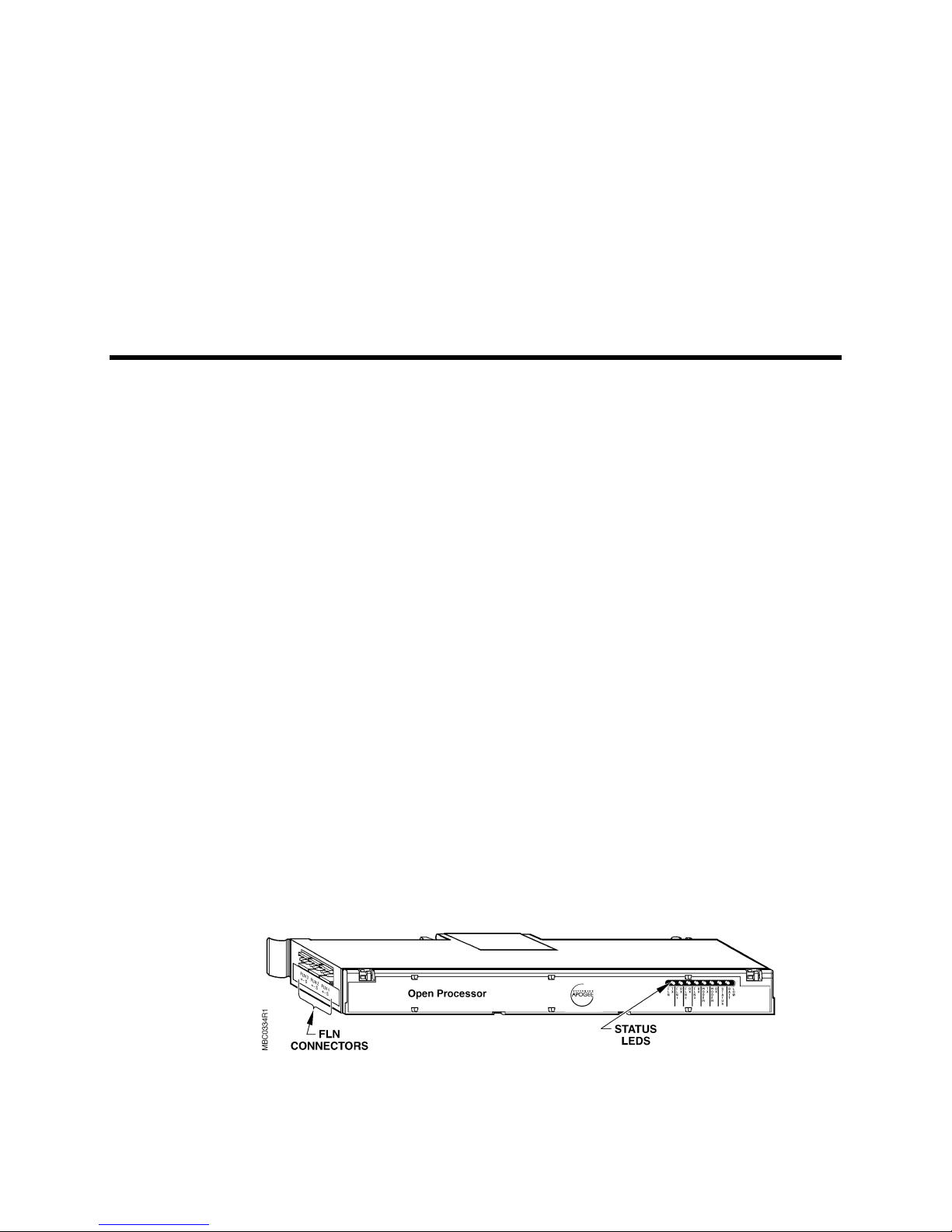
Figure 1-1 shows an Open Processor.
Siemens Building Technologies, Inc. 1-1
Landis Division
FFFFiiiigu
gurrrre
gugu
e 1111----1111.
e e
. TTTThe
he OOOOppppen
. .
he he
en PPPPrrrroooocccceeeess
en en
ssoooorrrr....
ssss
Page 10

Open Processor with Trane Driver Owner's Manual
CCCCoooommmmppppaaaattttiiiibbbbili
ilittttyyyy
iliili
The Open Processor is compatible with the following products:
GGGGaaaatttthe
herrrriiiing
ng aaaand
hehe
ng ng
EEEExxxxeeeeccccuuuuttttiiiing
ng CCCCon
ng ng
APOGEE Insight
x
Stand-alone Control Unit (SCU), Revision 6.1 or greater
x
Local Area Network (LAN) Controller
x
Remote Control Unit Protocol 2 (RCU P2)
x
Modular Equipment Controller (MEC)
x
Modular Building Controller (MBC)
x
Remote Building Controller (RBC)
x
Floor Level Network (FLN) Controller
x
nd PPPPrrrroooocccceeeessi
nd nd
The Open Processor samples the Trane network inputs, or
numerical representations of these values. The Open Processor then takes the required
action; that is, it either adds current information to the history file or sends an alarm message
to the proper location.
ontr
trooool
onon
trtr
ssing
ssissi
l PPPPrrrrog
ogrrrram
l l
ogog
ng FFFFiiiieeeelllld
ng ng
amssss
amam
“
for Personal Computers
d IIIInpu
nputtttssss
d d
npunpu
, for information and stores
points
The Open Processor continuously executes a user-defined set of instructions called the
control program
time. The control program performs the following functions:
Evaluates control strategies.
x
Uses an internal calendar and time clock for time-based functions.
x
Updates point values, and commands field points according to the program results.
x
Sends alarms, messages, or reports to proper terminal locations as needed.
x
PPPPrrrroooocccceeeessi
ssing
ng OOOOpe
ssissi
1-2 Siemens Building Technologies, Inc.
perrrraaaattttoooor
ng ng
pepe
An operator can issue commands or requests to the Open Processor using an operator
terminal and the operator interface program that resides in the Open Processor. Reference
the
System 600 APOGEE Field Panels User’s Manual
access levels.
. This program uses the most recent point values and the most recent clock
r CCCCoooomma
mmand
mmamma
ndssss
ndnd
(125-3000) for more information on
Landis Division
r r
Page 11

Introduction
Valid operator commands to change point values or to command field points are handled
similarly to field input or control program commands. For example, if an operator issues an
ON command to a fan starter, the Open Processor issues the ON command to the field point
and updates the value in its memory. In this case, the operator overrides the control program.
The fan point would remain ON until the operator commands the fan OFF or until the
operator releases the point back to automatic control.
BBBBuuuuil
ilddddiiiing
ng LLLLeeeevvvveeeel
ilil
ng ng
NOTE:
l NNNNeeeetw
l l
Up to 100 Open Processors and field panels (addressed 0-99) can be connected on a building
level network (BLN), also known as a Protocol 2, P2, or peer-to-peer network. Information
from any Open Processor or field panel on the BLN can be accessed and shared. The BLN
provides connections within or between buildings by using dedicated network wiring,
dedicated telephone lines, or dial-up telephone lines.
More than one operator can access the network at one time. For example, as one operator
accesses the system, another operator can access the system at another terminal or from a
remote site by using a modem. Alarms are reported to the alarm printer even as an operator
accesses information.
When an operator issues a command over the network, the Open Processor or field panel at
which the operator issued the command does the following:
x
x
x
Either the Open Processor or the Trane system can command Trane equipment
controllers.
twoooorrrrkkkk
twtw
Validates the command,
Determines the command’s destination.
Passes the command to the destination over the network.
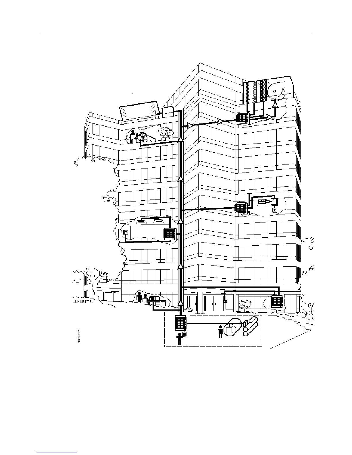
Figure 1-2 illustrates the following process: The operator issues a command at the Open
Processor. The Open Processor is located in the lower level of the building. This command is
sent through the BLN to the Open Processor located on the penthouse to control the main air
handling unit of the building.
For more information about networking, contact your local Siemens Building Technologies
representative.
SSSSiiiing
nglllle
e OOOOpen
ngng
Siemens Building Technologies, Inc. 1-3
Landis Division
pen PPPPrrrroooocccceeeess
e e
pen pen
The Open Processor can operate as a stand-alone controller. A single Open Processor is
typically used in remote sites where only the equipment for that site needs to be controlled.
Communications with the remote site is achieved using modems.
ssoooor
r RRRReeeemmmmooootttte
ssss
r r
e SSSSiiiitttteeeessss
e e
Page 12

Open Processor with Trane Driver Owner's Manual
The remote-site Open Processor can initiate a telephone call to a printer, a dumb terminal, or
a minicomputer or personal computer running Insight software. Once the remote site
connects to the device, an alarm or other user-defined event is issued. When the remote site
no longer requires the connection to the device, the remote site disconnects. The remote
site can also receive telephone calls from a device running Insight software to allow
centralized access of a local network database.
For more information about remote site Open Processors, contact your local Siemens
Building Technologies representative.
1-4 Siemens Building Technologies, Inc.
Landis Division
Page 13
Introduction
Siemens Building Technologies, Inc. 1-5
Landis Division
FFFFiiiigu
gurrrre
gugu
e 1111----2222.
e e
. CCCCoooomm
mmaaaannnnddddiiiing
. .
mmmm
ng OOOOvvvveeeer
ng ng
r a
a NNNNeeeettttwwwwoooorrrrkkkk....
r r
a a
Page 14

Open Processor with Trane Driver Owner's Manual
Notes
1-6 Siemens Building Technologies, Inc.
Landis Division
Page 15

2
2
22
HHHHaaaard
rdwa
rdrd
ware
re
wawa
rere
CCCChhhhaaaappppte
SSSSys
ter
tete
ystttteeeem
m CCCCon
ysys
m m
r OOOOvvvveeeerrrrvi
r r
Chapter 2 describes the hardware components of the Open Processor, and the function of
Trane devices. The Open Processor allows some control and monitoring functions that
formerly required hard-wired interfaces between the System 600 and field equipment. By
using the Open Processor, much of the expense of field wiring can be eliminated. The
following topics are included in Chapter 2:
The Open Processor with Trane driver enables the System 600 APOGEE to monitor and/or
control the Trane Tracer Summit™ Building Control Unit (BCU).
The integrated system consists of the Trane system and the System 600 APOGEE, linked by
the Open Processor and Trunk Interface II. The Trane System consists of a BCU
communicating with many Trane equipment controllers.
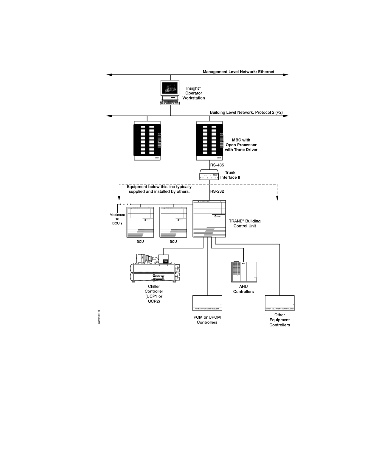
Figure 2-1 diagrams a typical Trane and System 600 APOGEE configuration.
vieeeewwww
vivi
System Configuration
x
System 600 APOGEE Components
x
Trane Components
x
onffffiiiigu
onon
gurrrraaaattttiiiion
gugu
on
onon
Siemens Building Technologies, Inc. 2-1
Landis Division
Page 16
Open Processor with Trane Driver Owner's Manual
SSSSys
ystttteeeem
m 600
ysys
Modu
Modullllaaaar
ModuModu
2-2 Siemens Building Technologies, Inc.
600 AAAAPPPPOOOOGGGGEE
m m
600 600
r BBBBuuuuil
ilddddiiiing
r r
ng CCCCon
ilil
ng ng
The Open Processor may reside in any Modular Building Controller (MBC) or Remote Building
Controller (RBC) enclosure with an open slot on the communications bus (C-Bus).
EE CCCCoooommmmpppponen
EE EE
ontr
trooooll
lleeeer
onon
trtr
llll
FFFFiiiigu
gurrrre
e 2222----1111.
gugu
e e
r oooor
r RRRReeeemmmmooootttte
r r
r r
. TTTTyyyyppppiiiica
cal
l TTTTrrrraaaane
. .
caca
l l
onenttttssss
onenonen
e BBBBuuuuil
e e
ne aaaannnnd
d SSSSys
nene
d d
ilddddiiiing
ng CCCCon
ilil
ng ng
ystttteeeem
m 600
ysys
m m
ontr
onon
600 AAAAPPPPOOOOGGGGEE
600 600
trooooll
lleeeer
r EEEEnnnncccclllloooossssuuuurrrreeee
trtr
llll
r r
EE CCCCon
onffffiiiigu
EE EE
onon
gurrrraaaattttiiiion
on....
gugu
onon
Landis Division
Page 17
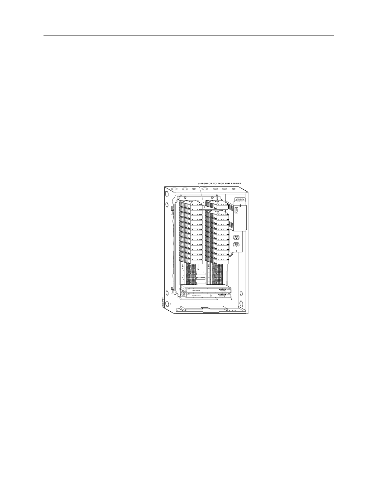
In addition, the Open Processor does the following:
Supports Expansion Module Kits.
x
Does not require a Power Module in the enclosure unless the Open Processor
x
controls Point Termination Modules (PTMs).
Can reside in an enclosure that contains a Power Module and one or more Controller
x
Modules and/or
Open Processors.
other
Other
supporting one of a variety of communication drivers.
Hardware
Open Processors are those capable of
NOTE:
An MBC enclosure is FCC-approved for a maximum of four Controller Modules
and/or Open Processors.
Figure 2-2 shows an MBC enclosure with various modules.
OOOOpen
pen PPPPrrrroooocccceeeess
pen pen
ssoooor w
r wiiiitttth
ssss
r wr w
h TTTTrrrraaaane
ne DDDDrrrriv
h h
ne ne
The Open Processor with Trane driver is a high-performance, independent controller that is
customized to meet your exact building control needs. It controls mechanical equipment and
performs specialized applications using Direct Digital Control (DDC). The Open Processor
with Trane driver can communicate with System 600 APOGEE field panels and Insight
workstations. It can be implemented as a central monitoring unit or remote site equipment
controller, and can communicate with the point modules in the cabinet.
Data about Trane equipment controllers for controlling, displaying, logging, alarming, and
trending on the System 600 APOGEE is made available by the Open Processor, shown in
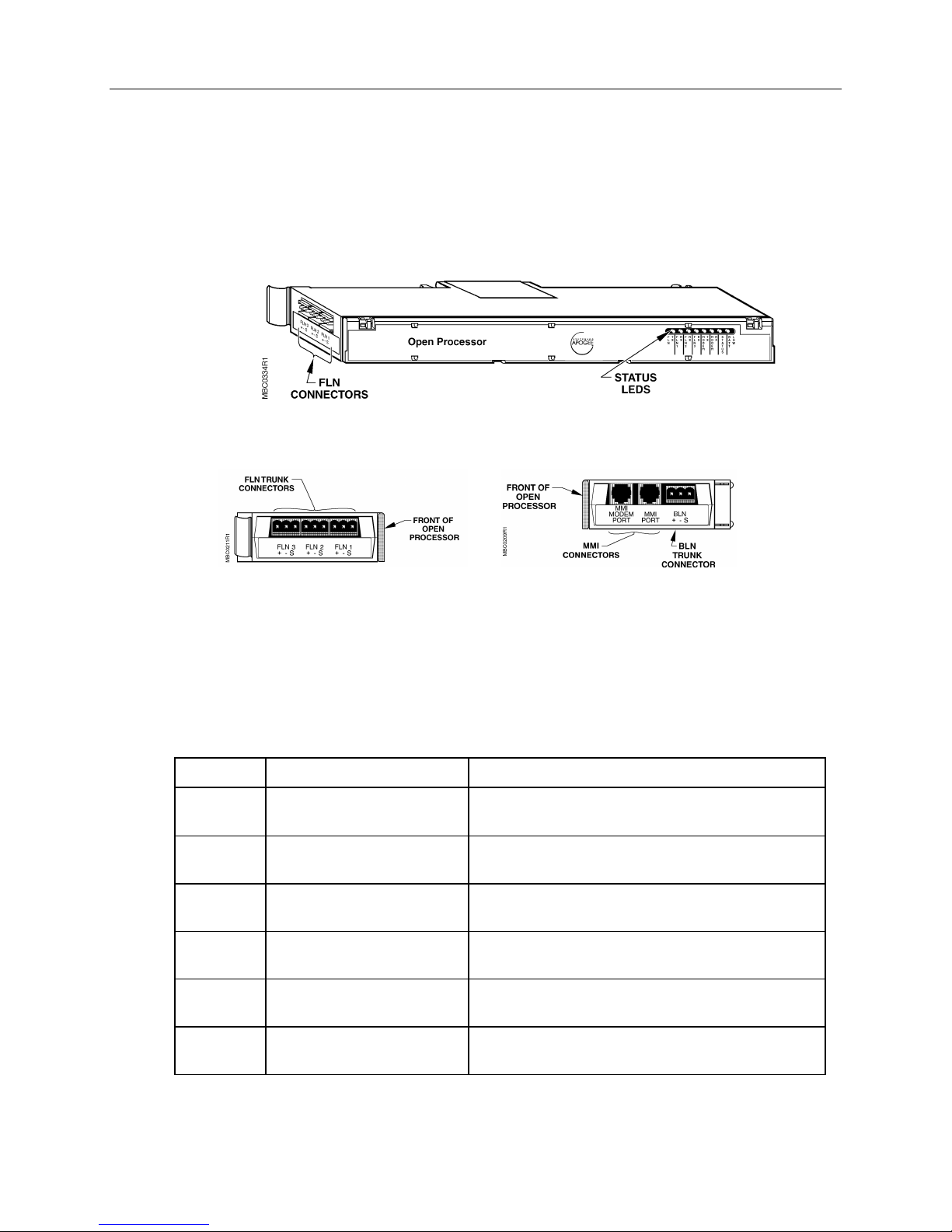
Figure 2-3, Figure 2-4, and Figure 2-5. Points in the Open Processor’s database hold
information about Trane equipment controllers.
Siemens Building Technologies, Inc. 2-3
Landis Division
iveeeerrrr
iviv
FFFFiiiigu
gurrrre
gugu
e 2222----2222.
e e
. MMMMBC
BC EEEEnnnncccclllloooossssuuuurrrre
. .
BC BC
e wwwwiiiitttth
e e
h DDDDoo
oor
h h
oooo
r RRRReeeemmmmoooovvvveeeedddd....
r r
Page 18
Open Processor with Trane Driver Owner's Manual
The Open Processor with Trane driver cannot communicate with any other FLN devices such
as Terminal Equipment Controllers. The Open Processor connects to the Trane system using
only the FLN 1 port. However, the Open Processor uses the address space of FLN 1, FLN 2,
and FLN 3.
FFFFiiiigu
gurrrre
e 2222----3333.
gugu
e e
. OOOOppppen
en PPPPrrrroooocccceeeess
. .
en en
ssoooor
ssss
r ((((FFFFrrrron
ont
r r
onon
t VVVViiiieeeewwww).
t t
).
).).
OOOOpen
pen PPPPrrrroooocccceeeess
pen pen
Green FLN TX Open Processor is transmitting information over
Green FLN1 RX Open Processor is receiving information over the
Green BLN TX Open Processor is transmitting information over
Green BLN RX Open Processor is receiving information over the
Green STATUS Open Processor is powered up and operating
FFFFiiiigu
gurrrre
e 2222----4444.
. OOOOppppen
ssoooor
r LLLLEEEEDDDDssss
ssss
r r
gugu
e e
((((LLLLeeeeft
. .
ft SSSSiiiidddde
ft ft
en PPPPrrrroooocccceeeess
en en
e VVVViiiieeeewwww).
e e
ssoooorrrr
ssss
).
).).
FFFFiiiigu
gurrrre
gugu
e 2222----5555.
e e
((((RRRRiiiigh
ght
ghgh
. OOOOppppen
en PPPPrrrroooocccceeeess
. .
en en
t SSSSiiiidddde
e VVVViiiieeeewwww).
t t
e e
ssoooorrrr
ssss
).
).).
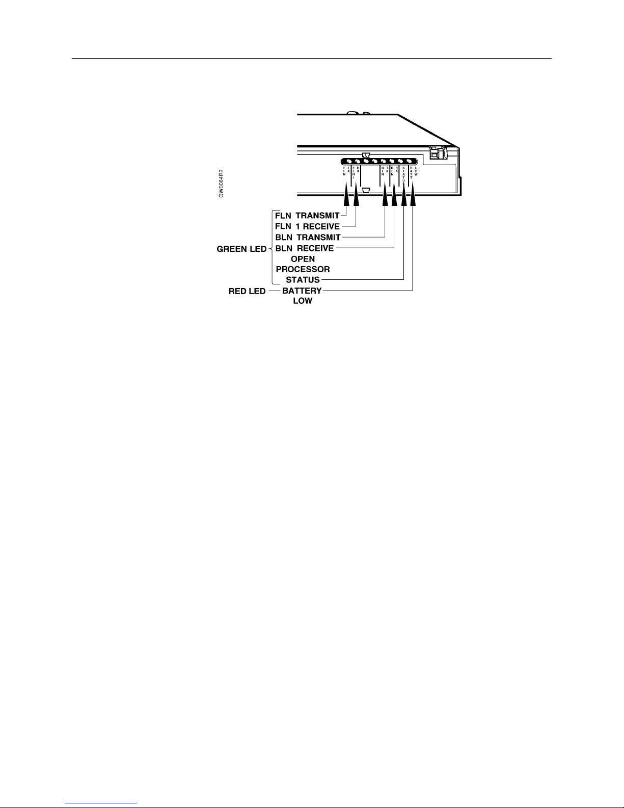
Eight LEDs are located on the front of the Open Processor, but only six are active. Each LED
is labeled according to its function. Refer to Table 2-1 and Figure 2-6 for additional
information.
TTTTaaaabbbblllle
e 2222----1111.
. OOOOppppen
e e
. .
CCCCoooolllloooorrrrL
lD
LLLaaaabbbbeeeelll
en PPPPrrrroooocccceeeess
en en
ssoooor
ssss
r LLLLEEEEDDDDssss....
r r
DDDeeeessssccccrrrriiiippppttttiii
ion
on
onon
the FLN 1 trunk.
FLN 1 trunk.
the BLN trunk.
BLN trunk.
properly when this LED is flashing.
Red BATT LOW The Open Processor backup battery is low.
2-4 Siemens Building Technologies, Inc.
Replace the battery.
Landis Division
Page 19
FFFFiiiigu
gurrrre
gugu
e 2222----6666.
e e
. OOOOppppen
en PPPPrrrroooocccceeeess
. .
en en
ssoooor
ssss
r LLLLEEEEDDDDssss....
r r
Hardware
OOOOtttthe
her
r OOOOpen
hehe
r r
PPPPoooowwwweeeer
r Modu
r r
pen PPPPrrrroooocccceeeess
pen pen
Other Open Processors are those capable of supporting one of a variety of communication
drivers.
Other Open Processors also gather information about building systems that they monitor and
sometimes control. The information from the building systems is then stored into standard
System 600 APOGEE point types.
For more information about other Open Processors and associated drivers, contact your local
Siemens Building Technologies representative.
Modulllleeee,
ModuModu
The Open Processor does not require a Power Module or a Controller Module when it is in an
MBC or RBC enclosure. However, Power Modules and Controller Modules can share an
MBC or RBC enclosure with Open Processors.
NOTE:
For more information about Power Modules and Controller Modules, refer to the
Modular Building Controller and Remote Building Controller Owner’s Manual
ssoooorrrrssss
ssss
, CCCCon
ontr
trooooll
lleeeer
r Modu
, ,
onon
trtr
If an Open Processor controls PTMs, a Power Module is required.
llll
r r
Modulllleeee
ModuModu
System 600
(125-1992).
EEEExxxxppppaaaannnnsi
Siemens Building Technologies, Inc. 2-5
Landis Division
sion Modu
on Modulllle
sisi
on Moduon Modu
Expansion Module Kits contain communication devices that join the Module Bus (M-Bus) of
two sets of MBC or RBC enclosures when the first enclosure reaches its maximum point
capacity.
e KKKKiiiitttt
e e
Page 20

Open Processor with Trane Driver Owner's Manual
The Expansion Module Kit contains two different types of modules: the Primary Module (PM)
and the Expansion Module (EM). The PM is installed in the
with the Open Processor or Controller Module). The primary panel is responsible for
controlling PTMs installed within that enclosure, as well as any enclosures with Expansion
Module Kits joined to the primary panel.
primary panel
(an MBC or RBC
The EM is installed in the
Controller Module). The purpose of the expansion panel is to provide extra PTM slots for the
primary panel to use.
For more information about Expansion Module Kits, refer to the
Building Controller and Remote Building Controller Owner’s Manual
PPPPooooiiiinnnnt
t TTTTeeeerrrrmmmmiiiinnnnaaaattttiiiion Modu
t t
Point Termination Modules (PTMs) are signal converters that have one, two, or four points.
PTMs are the interface between the field equipment and an Open Processor or a Controller
Module. Field equipment includes devices that provide information to, or are controlled or
monitored by an Open Processor or a Controller Module. All field input and output points are
either digital points or analog points such as 4mA–20mA sensors, 0Vdc–10Vdc outputs to
control actuators, and pulse accumulators.
For more information about PTMs, refer to the
Remote Building Controller Owner’s Manual
OOOOpe
perrrraaaattttoooor
pepe
r IIIInnnntttteeeerf
rfac
r r
rfrf
Operator interfaces, such as operator terminals (PCs, laptops), video display terminals, and
printers, allow you to communicate with the Open Processor.
on Modulllleeeessss
on Moduon Modu
aceeeessss
acac
expansion panel
(an MBC or RBC without an Open Processor or
System 600 Modular
(125-1992).
System 600 Modular Building Controller and
(125-1992)
.
OOOOpe
perrrraaaattttoooor
pepe
2-6 Siemens Building Technologies, Inc.
r TTTTeeeerrrrmmmmiiiinnnnaaaals
r r
Operator terminals allow you to communicate interactively with the Open Processor. A
keyboard is used for input, and a video screen or printer is used to display (echo) your inputs
and the system responses. Operator terminals allow you to do the following:
ls
lsls
Directly control or request information about Open Processor points.
x
Check the operation of Trane building controls.
x
Change or override control programs in the Open Processor.
x
Landis Division
Page 21

VVVViiiideo
deo DDDDis
deo deo
Request and receive a variety of Trane system and point status reports.
x
Change the definition of points in the system.
x
Define the destinations of alarm messages and reports.
x
Control operator access to the system (set up operator access levels and
x
passwords).
Create backup copies of user-defined control programs (using a PC or a laptop).
x
Transmit messages between operator terminals.
x
isppppllllaaaay
y TTTTeeeerrrrmmmmiiiinnnnaaaals
isis
y y
Video display terminals and printers transmit information from the Open Processor to the
operator. These two devices allow you to do the following:
x
ls aaaand
nd PPPPrrrriiiinnnntttteeeerrrrssss
ls ls
nd nd
Receive and print reports.
Hardware
Mode
Modemmmmssss
ModeMode
Receive alarms.
x
Receive and print alarm messages.
x
Modems can transmit data from an Open Processor to an operator interface over telephone
lines. Therefore, remote communication between the Open Processor and an operator
interface is possible using two modems—one at each end of the communication link. For
example, an alarm printer can be set up in a building manager's office to receive alarms from
an Open Processor that is in a remote location.
Modems may be used along with leased telephone lines to link remote Open Processors in a
networked system and to link remote Open Processors with a centrally located mass storage
device such as a personal computer running Insight for Personal Computers.
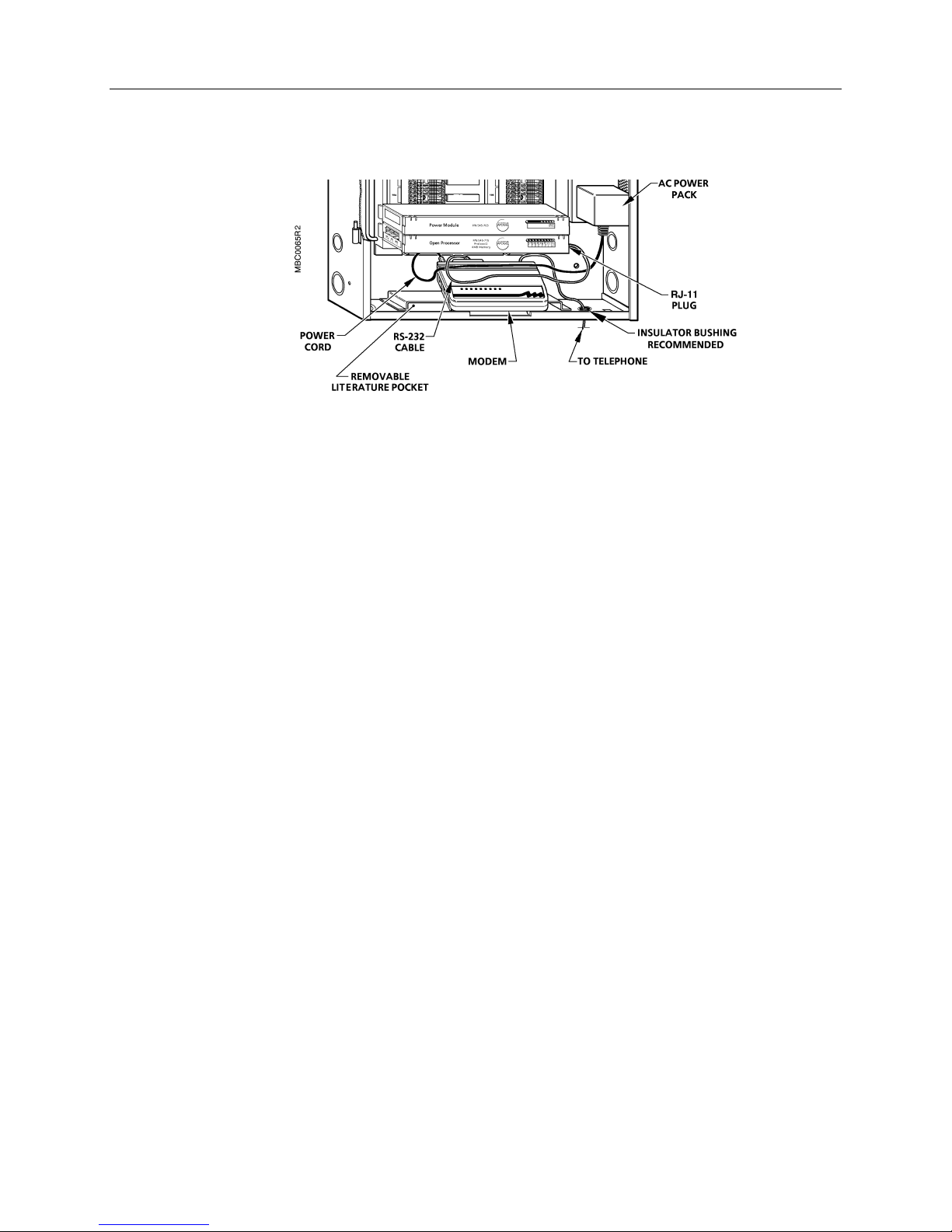
A modem approved for your application can be installed within the MBC or RBC enclosure. A
cable connects the modem's RS-232 port to the MMI/MODEM port on the Open Processor.
Refer to Figure 2-7. If you need more room for the modem, remove the literature pocket by
lifting up on the center of the pocket until the ends slide out from underneath the two tabs
on both sides.
NOTE:
The communication speed (baud rate) of the modem and the MMI/MODEM port
must match.
For more information about modems approved for use with the Open Processor, contact
your local Siemens Building Technologies representative.
Siemens Building Technologies, Inc. 2-7
Landis Division
Page 22
Open Processor with Trane Driver Owner's Manual
FFFFiiiigu
gurrrre
e 2222----7777.
gugu
e e
TTTTrrrraaaane
ne CCCCoooommmmpppponen
ne ne
onenttttssss
onenonen
The Open Processor enables the Siemens Building Technologies System 600 APOGEE to
communicate with up to 18 Trane Tracer Summit™ Building Control Unit (BCU) Panels. Thus,
the integrated system consists of the Trane system plus the System 600 APOGEE, linked by
the Open Processor.
. TTTTyyyyppppiiiica
cal
. .
caca
l MMMMooooddddeeeem
m IIIInnnnssssttttaaaall
l l
m m
llaaaattttiiiion
on....
llll
onon
TTTTrrrrac
aceeeer
acac
r SSSSuuuumm
mmiiiitttt™
r r
™ HHHHaaaarrrrddddwwwwaaaarrrre
mmmm
™ ™
Information regarding Tracer Summit hardware installation requirements may be found in the
Trane Tracer Summit Hardware Installation Book
mounting, wiring requirements, modem communications information and Trane Summit BCU
LAN hookup instructions.
e IIIInnnnssssttttaaaall
e e
llaaaattttiiiion
on
llll
onon
, Volume 1. The book addresses BCU
2-8 Siemens Building Technologies, Inc.
Landis Division
Page 23

3
3
33
SSSSooooft
ftwa
ftft
ware
re
wawa
rere
CCCChhhhaaaappppte
OOOOppppen
ter
tete
en PPPPrrrroooocccceeeess
en en
r OOOOvvvveeeerrrrvi
r r
Chapter 3 describes the software that comes installed in the Open Processor. The following
topics are covered in Chapter 3:
The Open Processor software runs automatically when the Open Processor is powered up.
When properly configured, the Open Processor establishes communications with the
remainder of the System 600 APOGEE and the Trane system, and begins relaying data.
The Open Processor contains the following software:
vieeeewwww
vivi
Open Processor Software
x
Trane Driver
x
Operator Interface
x
PPCL
x
ssoooor
r SSSSooooft
r r
ftwwwwaaaarrrreeee
ftft
ssss
System 600 APOGEE Trane driver
x
Operator interface
x
Powers Process Control Language (PPCL)
x
TTTTrrrraaaane
ne DDDDrrrriv
iveeeerrrr
ne ne
iviv
The Trane driver allows the Trane system to communicate directly with the System 600
APOGEE.
Siemens Building Technologies, Inc. 3-1
Landis Division
Page 24

Open Processor with Trane Driver Owner's Manual
OOOOpe
perrrraaaattttoooor
pepe
r IIIInnnntttteeeerf
rfac
r r
aceeee
rfrf
acac
An operator issues commands or requests to the Open Processor using an operator terminal
and the
communicate interactively with the Open Processor.
operator interface
. The operator interface is the software that allows the operator to
PP
PPCCCCLLLL
PPPP
The operator interface is described in detail in the
Manual
operator interface. It describes the functions necessary for everyday operation of your
system, plus the higher level functions for commanding, displaying, editing, scheduling,
networking, alarm management, and others.
For experienced users of the operator interface, the
Manual Quick Reference Guide
strings and the keystrokes necessary to access the functions.
The programming language used with the Open Processor is called
Language (PPCL)
controlling Heating, Ventilating, and Air Conditioning (HVAC) equipment.
The control configuration and control requirements of your system are customized into each
application by using PPCL. You can incorporate the following applications into the operation
of your system
(125-3000). This manual is designed to help you become familiar with and use the
(125-3001) contains a listing of the operator interface prompt
. PPCL is a powerful programming language developed specifically for
Alarm Management
x
Auto-Dial/Dial-Up
x
Daylight Savings Time
x
System 600 APOGEE Field Panel User's
System 600 APOGEE Field Panel User's
Powers Process Control
Duty Cycling
x
Enthalpy and Dry Bulb Economizer Control
x
Field Panel/Equipment Controller Coordinator
x
Loop Tuning (future)
x
Peak Demand Limiting (PDL)
x
Start/Stop Time Optimization (SSTO)
x
Time-Of-Day (TOD) Scheduling
x
Trend Data Collection
x
The
Powers Process Control Language (PPCL) User's Manual
on designing, coding, and implementing PPCL programs. It lists and defines all PPCL control
commands, control applications, syntax, and functionality.
3-2 Siemens Building Technologies, Inc.
(125-1896) contains information
Landis Division
Page 25

4
4
44
PPPPooooiiiinnnnt
CCCChhhhaaaappppte
t DDDDaaaattttaaaabbbbaaaasssseeee
t t
ter
tete
r OOOOvvvveeeerrrrvi
r r
Chapter 4 describes the Open Processor point database, including point definition
information, dynamic point information, point database structure, point addresses, and slopes
and intercepts. The following topics are included in Chapter 4:
vieeeewwww
vivi
What is a Point Database?
x
Types of Logical Points
x
Virtual Points
x
Local Points
x
Point Characteristics
x
Point Type Attributes
x
BCU Mapping/Metapoints
x
BACnet
x
¥
Point Database Guidelines
x
Most tasks that the Open Processor performs involve either collecting data from Trane
equipment controllers or commanding them. Other tasks require communication and
calculations within the control programs using stored information. Operators also need a
practical method of commanding and examining points. With the Open Processor, operators
use the commands and menu-driven prompts of the operator interface.
The point database is created by supplying the Open Processor with logical points and
information about the Trane BACnet objects. There are two basic classifications of point
information that make up the point database: information used to define Trane BACnet
objects, and information that is updated or set during operation of the Trane system.
In order to monitor and/or control Trane equipment controllers, points must be added to the
point database. For details about defining these points, refer to the point addressing
information that follows. For additional information about adding or modifying points in the
database, refer to the
Siemens Building Technologies, Inc. 4-1
Landis Division
System 600 APOGEE Field Panel User’s Manual
(125-3000).
Page 26

Open Processor with Trane Driver Owner's Manual
WWWWhhhhaaaat
t iiiis
t t
TTTTyyyyppppeeees
s oooof
s s
Information for specific Trane equipment controllers is listed in
s a
a PPPPooooiiiinnnnt
s s
a a
The point database is a file containing all information defined for every point in the System
600 APOGEE. The system controls points according to their definition and the purpose they
represent. Points are classified as follows:
LLLLog
ogiiiica
ogog
unique 30-character name. This name is referenced by operators, control programs, and the
other system features to command, examine, and store information for those points.
PPPPhhhhys
connected to a field input/output termination.
VVVViiiirt
points generally store values such as set points and results from calculations.
LLLLooooca
program, such as ALMCNT\.
f llllog
f f
All logical points are composed of one or more of the four basic point types. The basic point
types are Analog Input (AI), Analog Output (AO), Digital Input (DI), and Digital Output (DO).
Table 4-1 lists all available logical point types used by the Trane system:
t DDDDaaaattttaaaabbbbaaaasssseeee????
t t
cal
l ppppooooiiiinnnnttttssss – A grouping of one to four physical and/or virtual point addresses under a
caca
l l
ysiiiica
cal
l ppppooooiiiinnnnttttssss – Points which the system uses to reference the actual physical devices
ysys
caca
l l
rtuuuuaaaal
l ppppooooiiiinnnnttttssss – Points residing in memory that do not represent a piece of equipment. Virtual
rtrt
l l
cal
l ppppooooiiiinnnnttttssss – Standard system points residing in a PPCL program that are specific to that
caca
l l
ogiiiica
cal
ogog
l ppppooooiiiinnnnttttssss
caca
l l
Chapter 5, Applications
.
PPPPooooiiiinnnnt
t TTTTyyyyppppe
e aaaannnnd
t t
1 - AI (numeric value)
1 - AO (numeric value)
1 - DI (ON/OFF)
1 - DO (ON/OFF)
1 - Analog (multiple value
point–numeric only)
d CCCCoooommmmppppoooossssiiiittttiiiion
e e
d d
LLLLAAAAIIII
LLLLAAAAOOOO
LLLLDDDDIIII
LLLLDDDDOOOO
LLLLEEEENU
NUMMMM
NUNU
TTTTaaaabbbblllle
e 4444----1111.
. LLLLog
ogiiiica
cal
l PPPPooooiiiinnnnt
e e
. .
ogog
on DDDDeeeessssccccrrrriiiippppttttiiiion
onon
Logical Analog Input- Monitors one AI point. For example,
sensors for temperature, flow, pressure, and humidity.
Logical Analog Output - Commands one AO point. For
example, positioners for dampers, valves, and motors.
Logical Digital Input - Monitors one latched DI point. For
example, door contacts, smoke detectors, low
temperature detectors, and damper end switches.
Logical Digital Output - Commands one latched DO point
for a two state (ON/OFF) device. For example, switches
for lighting and occupancy indication.
Logical ENUMerated - Control points that have multiple
numeric values. Each value is associated with a state text
entry. For example, a LENUM point can be a virtual point
that stores operational values for an SSTO application.
LENUMS are defined as virtual.
caca
l l
t TTTTyyyyppppeeeessss....
t t
on
onon
4-2 Siemens Building Technologies, Inc.
Landis Division
Page 27

VVVViiiirt
rtuuuuaaaal
rtrt
l PPPPooooiiiinnnnttttssss
l l
Point Database
EEEExam
xampppplllleeeessss
xamxam
A virtual point is a logical point without a physical device. Refer to the
Field Panel User’s Manual
The following examples demonstrate how virtual points can be used:
FFFFoooor
r sssseeeet
t po
poiiiinnnnttttssss::::
r r
t t
popo
Virtual points can store desired values such as temperature, relative humidity, and pressure.
For the system to make adjustments to control equipment, the system needs to compare
the actual value to the desired value. The field panel stores the desired value in memory as a
virtual analog output point.
FFFFoooor
r ope
operrrraaaattttiiiion
r r
opeope
Virtual points are often used to store operational data. For example, a virtual point can be
used to store the high and low temperatures for outside air. Applications such as Start/Stop
Time Optimization (SSTO) use virtual points for different types of values.
FFFFoooor
r a
a ttttiiiimmmmeeee////ddddaaaatttteeee::::
r r
a a
PPCL uses times and dates to accomplish building control.
onaaaal v
l vaaaallllue
onon
l vl v
(125-3000).
uessss::::
ueue
System 600 APOGEE
LLLLooooca
cal
l ppppooooiiiinnnnttttssss
caca
l l
Every PPCL program has a set of fixed local points. Local points are used primarily in PPCL
programming. Refer to the
User’s Manual
PPPPooooiiiinnnnt
t cccchhhhaaaarrrrac
t t
Siemens Building Technologies, Inc. 4-3
Landis Division
actttteeeerrrriiiissssttttiiiiccccssss
acac
Each point (logical or virtual) is composed of attributes that define it in the database. These
attributes are:
(125-3000) for more information on using local points.
PPCL Editor
chapter of the
System 600 APOGEE Field Panel
Page 28

Open Processor with Trane Driver Owner's Manual
Point name/point system name
x
Point address
x
Point status
x
Point priority
x
Point value/state
x
PPPPooooiiiinnnnt
t nnnnam
ameeee////po
poiiiinnnnt
t sys
systttteeeem
m nnnnam
t t
amam
popo
t t
syssys
m m
ameeee
amam
The
point name
database. The
them with different names. Both names, whether they are set equal or defined differently,
must be unique on the network.
Having two names provides the ability to customize the database without affecting the
control of the system. PPCL programs (which exclusively use the point system name) remain
unchanged if the point name is changed.
Each user account defines the type of name that is displayed in the interface. Those with
access see the point name. Those with
User
When viewing PPCL programs, the system always displays the point system name
regardless of the access settings.
The following example illustrates a point name and a point system name:
Point name:
Point system name:
For points on an FLN device, or in applications, a suffix is used with the device or application
name. For these types of points, the FLN device/application is referenced first, followed by a
colon, followed by the suffix (the name of the subpoint).
Below is an example of referencing a point on an FLN device called
and
point system name
point system name
%8,/',1*41$+84163$&(7(03
%4$467
are the labels that identify a particular point in the
and
point name
can be the same. You may also define
System
access see the point system name.
%8,/',1*#409$945
:
%8,/',1*#409$945='25
Below is an example of referencing a local set point in a PPCL program called
:$508302'(=6(732,17
4-4 Siemens Building Technologies, Inc.
:$508302'(
Landis Division
:
Page 29

PPPPooooiiiinnnnt
t nnnnam
amiiiing
t t
amam
Point Database
ng ccccon
onvvvven
enttttiiiion
ng ng
onon
Naming conventions provide a consistent and predictable organization for points. The
following guidelines are recommended:
x
onssss
enen
onon
When designing a point database, identify common segments or groupings for point
names. Larger facilities may use six or more segments to name points. Smaller
facilities may choose a simpler convention by using only three or four segments. The
most common segments and order are as follows:
State
Campus
Building or Department
Floor, Room, or Area
Equipment (boiler, chiller, air handler, etc.)
Device
The names should be structured hierarchically, moving from global (far left
x
characters), to specific (far right characters). For example:
LIB.CHILL02.CWT 773 248 3607
ð
(room, equipment, device)
BLD990.FLR01.AHU01.SAT
ð
(building, floor, equipment, device)
Only alphanumeric characters and periods should be used in point names.
x
Do not use underscores.
ð
Use periods only as separators between sections. Do not use periods in
ð
abbreviations.
Do not begin a point name with a period.
ð
If one or more points on a job lacks a section that you identified in your point naming
x
conventions, insert a period for the missing section. For example:
BLD990.FLR01.AHU01.SAT
ð
BLD990.FLR01..SAT
ð
The equipment section is missing in the second point name, replaced by two
ð
periods.
Siemens Building Technologies, Inc. 4-5
Landis Division
Page 30

Open Processor with Trane Driver Owner's Manual
Program names should be the same as the point names and equipment they control,
x
but without the suffix. For example:
SSSSaaaavi
ving
ng ttttiiiimmmme
vivi
ng ng
PPPPooooiiiinnnnt
t aaaadd
ddrrrreeeess
t t
dddd
EEEEqqqquuuuiiiippppmmmmen
PPPPrrrrog
PPPPooooiiiinnnntttts
entttt:::: Building 990, Floor 1, Air Handling Unit 1
enen
ogrrrraaaam
m NNNNaaaammmmeeee::::
ogog
m m
s CCCCon
s s
ontr
trooooll
onon
trtr
lleeeedddd::::
llll
,/1%/'<<31)/5341$+834
,/1%/'<<31)/5341$+83416$7
,/1%/'<<31)/5341$+8341+9/
,/1%/'<<31)/5341$+83416)1
e wwwwhen en
hen entttteeeerrrriiiing po
e e
hen enhen en
ng poiiiinnnnt
ng pong po
t nnnnam
ameeeessss
t t
amam
Instead of typing an entire point name, the system allows the following shortcuts:
Wildcards allow for easier selection for names of points.
x
Query for point names can provide a numeric list of points to select from.
x
The quick text key can be used to define part of the point name.
x
Use command key shortcuts (such as CCCCtr
x
For examples of queries and wildcarding, refer to the
APOGEE Field Panel User’s Manual
ss
ssss
(125-3000).
trllll-PPPP and CCCCtr
trtr
Introduction
trllll-IIII from the paste buffer).
trtr
chapter of the
System 600
The Open Processor uses the standard Siemens Building Technologies addressing scheme
of TCCLDDPP. Refer to Table 4-2.
TTTTaaaabbbblllle
e 4444----2222.
. OOOOppppen
AAAAbb
bbrrrreeeevvvviiiiaaaattttiiiion
bbbb
e e
. .
on MMMMeeeeaaaannnniiiing
onon
ng RRRRaaaange
ngng
en PPPPrrrroooocccceeeess
en en
ssoooor
r PPPPooooiiiinnnnt
t AAAAdd
ddrrrreeeess
ssiiiing
ng SSSScccche
ssss
r r
t t
dddd
ssss
nge DDDDeeeessssccccrrrriiiippppttttiiiion
ngenge
ng ng
hemmmmeeee....
hehe
on
onon
T Trunk 0–3 As with other MBC or SCU
controllers, the individual building
level network (BLN) number is
always zero.
CC Cabinet 00–99 The cabinet number assigned to
the Open Processor (unique BLN
network node address).
NNNNOOOOTTTTEEEE:::: It is possible to have more
than one node in an enclosure.
L FLN 0–3 0: Virtual or PTM points
1–3: Trane points
ccccon
onttttiiiinue
nued
d on ne
on nexxxxt
t ppppaaaage
onon
nuenue
d d
on neon ne
ge…………
t t
gege
4-6 Siemens Building Technologies, Inc.
Landis Division
Page 31

AAAAbb
bbrrrreeeevvvviiiiaaaattttiiiion
bbbb
TTTTaaaabbbblllle
e 4444----2222.
. OOOOppppen
e e
. .
on MMMMeeeeaaaannnniiiing
onon
ng RRRRaaaange
ngng
en PPPPrrrroooocccceeeess
en en
ssoooor
r PPPPooooiiiinnnnt
t AAAAdd
ddrrrreeeess
ssss
r r
nge DDDDeeeessssccccrrrriiiippppttttiiiion
ngenge
ssiiiing
t t
dddd
ssss
ng SSSScccche
hemmmmeeee....
ng ng
hehe
on
onon
Point Database
DD Drop 0A–0Z
00–31
(FLN 0) 0A–0Z: Virtual point
drops
(FLN 1) 00–31: Trane drops
(FLN 2) 00–31: Trane drops
(FLN 3) 00–29: Trane drops
(FLN 3) 30: Metadrop
(FLN 3) 31: Diagnostic & Control
drop
PP Point 00–99 For Open Processor points, this is
a designated number derived as
shown in Section 5,
Applications
For physical points, this is a
number from the lists of points on
the following pages. Virtual points
may use any desired scheme.
NOTE:
If the Open Processor is to be used only to monitor and not to control Trane
equipment controllers, Siemens Building Technologies suggests that all points
listed as outputs (LAO and LDO) be defined instead as inputs (LAI and LDI).
All LDO points for the Open Processor are non-inverted.
All LAI points for the Open Processor should be defined as current (I) type.
.
The point address defines the location of the point in the field panel (whether on the M-Bus
or in an FLN device). Points on the M-Bus are addressed by:
Field panel - The name or number.
x
FLN - For points on the M-Bus, the FLN number is always 0.
x
Drop - The number of the address key on the Point Termination Module (PTM).
x
Point -The point number on the Point Termination Module (PTM).
x
NOTE:
Virtual points only require a field panel number, and cannot be defined on FLN
devices.
Siemens Building Technologies, Inc. 4-7
Landis Division
Page 32

Open Processor with Trane Driver Owner's Manual
PPPPooooiiiinnnnt
t ssssttttaaaattttuuuussss
t t
The point status indicates the current condition of a logical point as defined in the System
600 APOGEE database. It can also reflect two or more statuses. For example, a point may be
in alarm and failed at the same time, in which case the status would be *AF*. Table 4-3
gives an explanation of each status.
TTTTaaaabbbblllle
e 4444----3333.
e e
. PPPPooooiiiinnnnt
. .
t SSSSttttaaaattttuuuussss....
t t
SSSSttttaaaattttuuuussssM
ing
ng EEEExxxxppppllllaaaannnnaaaattttiiiion
MMMeeeeaaaannnniii
ngng
on
onon
-N- NORMAL The point is in regular operation. The value and alarm
conditions of the point can be updated by control
programs or operator commands.
*A* ALARM
The condition of the point is outside its defined limits
and an alarm priority has been assigned to the point.
An alarm occurs when: the value of an analog point is
outside a defined high or low limit. The value of a
proof point does not correspond to the commanded
value of the associated output point within the proof
delay time. An LDI or LDO point is ON and the point
was defined to go into alarm when it turns ON. An
example is a smoke detector point.
*An* ALARM
The condition of the point is outside its defined limits
and an enhanced alarm priority has bee assigned to
n
the point. The
represents the number of the alarm
level.
*AC* ALARM-BY-
COMMAND
The value of a point in its normal operating range,
however the point has been commanded into alarm
by an operator or by the control program. The point
remains in this state until it is commanded back to
the Normal state by an operator or control program.
*ACK* ACKNOWLEDGE The point is in alarm and has been acknowledged by
*F* FAILED The field panel is unable to command or read any of
*O* OPERATOR
DISABLED
4-8 Siemens Building Technologies, Inc.
a user.
the physical points associated with the logical point.
This may be the result of hardware failure or a sensor
reading outside of its defined limits.
The point has been disabled by an operator. The
point value and alarm conditions are not reported to
the BLN and cannot be updated by operator
commands or control programs until the point is
commanded back to Enabled.
ccccon
onttttiiiinue
nued
d on ne
on nexxxxt
t ppppaaaage
onon
nuenue
d d
on neon ne
ge…………
t t
gege
Landis Division
Page 33

TTTTaaaabbbblllle
e 4444----3333.
e e
. PPPPooooiiiinnnnt
. .
t SSSSttttaaaattttuuuussss....
t t
Point Database
SSSSttttaaaattttuuuussssM
ing
ng EEEExxxxppppllllaaaannnnaaaattttiiiion
MMMeeeeaaaannnniii
ngng
on
onon
*P* PROOFING The field panel is waiting to verify that the value of a
proof point corresponds to the commanded value of
an associated output point. The point is in this state
for as long as the proof delay time that is defined for
the point.
*HAND* HAND A PTM manual override switch has been used and
the system no longer has control of the point. The
system will not be able to control that point until the
PTM is switched back into AUTOMATIC mode.
*TBL* TROUBLE The point is in TROUBLE state. This status appears
when a PPCL program or user commands the point
to this state.
Siemens Building Technologies, Inc. 4-9
Landis Division
Page 34

Open Processor with Trane Driver Owner's Manual
PPPPooooiiiinnnnt
t pppprrrriiiioooorrrriiiittttyyyy
t t
The point priority determines if an operator or a particular control program is responsible for
controlling the point. The five priority levels are described in the Table 4-4.
CCCCoooomm
mmaaaannnnd
d PPPPrrrriiiioooorrrriiiittttyyyyD
mmmm
d d
TTTTaaaabbbblllle
e 4444----4444.
e e
. PPPPooooiiiinnnnt
t PPPPrrrriiiioooorrrriiiittttyyyy....
. .
t t
DDDeeeessssccccrrrriiiippppttttiii
ion
on
onon
OPER
(Operator)
The highest command priority. The control program is
overridden and an operator has direct control for commanding
the point. A point commanded by an operator must have its
priority lowered in order for the control program to resume
control of the point. This change in priority is known as
releasing a point
.
SMOKE The point is commanded by a smoke control program. Smoke
control is a special control program that monitors smoke
alarms.
EMER
(Emergency)
The point is commanded by an emergency control program.
Emergency control is a special control program that
commands a point during emergency situations, for example a
smoke detector goes into ALARM and turns on the exhaust
fan at EMER priority.
PDL
(Peak Demand
Limiting)
The point is commanded by a Peak Demand Limiting (PDL)
control program. PDL control is a special energy management
program that limits electrical demand by turning off electrical
loads when demand approaches a set point (for example
shutting down an air handling unit if demand approaches set
point).
NONE The lowest command priority level. The point can be
commanded by the standard PPCL control program. The point
is not controlled by the operator or special control programs.
Most point commanding in a building system is done
automatically by PPCL programs commanding points with the
NONE priority.
In most cases, the priority of a point should be NONE (under general system control).
Depending on the type of application, the system can change point priority to prevent
interaction by other applications (either by PPCL or an application). For example:
4-10 Siemens Building Technologies, Inc.
Landis Division
Page 35

Point Database
A point at NONE priority can be commanded by any PPCL program or application.
x
A point at PDL priority is being used by the PDL application. The point can be
x
commanded by other higher level applications (such as smoke control or operator),
but not by general PPCL programs or applications.
A point in OPER priority was commanded by a user. The system cannot command
x
the point until released back to system control. At any time, you can override any
application. The result of this action can change system performance.
The following methods are used to change point priority:
User interaction - the priority is changed manually via the interface.
x
A PPCL command - PPCL uses a command to directly change the point priority.
x
Once the point priority changes to NONE, it is available for commanding by general PPCL and
applications.
PPPPooooiiiinnnnt
t vvvvaaaallllue
uessss////ssssttttaaaatttteeee
t t
ueue
Analog points have numeric
point value is usually associated to an engineering unit that gives the value more meaning.
Digital points have
of one or more electronic switches. If a switch is energized, then the point is at a certain
state (for example, ON). For example:
PPPPooooiiiinnnnt
t SSSSttttaaaatttteeeeD
t t
Energized state ON (value 1)
De-energized state OFF (value 0)
State text allows the text used by each digital point to be redefined with more meaningful
text. The following example illustrates the difference between the default text and alternate
state text labels:
PPPPooooiiiinnnnt
t SSSSttttaaaatttteeeeD
t t
Energized state ON DIRTY
De-energized state OFF CLEAN
Refer to the System Profile chapter of the
(125-3000) for more information concerning the use of state text.
such as ON or OFF. A state is determined by the physical position
states
DDDeeeeffffaaaauuuulll
, identifying temperatures, positions, flow rate, etc. The
values
lt
t SSSSys
ystttteeeem
m TTTTeeeexxxxtttt
ysys
m m
te
e SSSSttttaaaatttte
AAAlllltttteeeerrrrnnnnaaaattt
System 600 APOGEE Field Panels User’s Manual
e e
e TTTTeeeexxxxtttt
e e
lt
t SSSSys
t t
DDDeeeeffffaaaauuuulll
t t
ystttteeeem
m TTTTeeeexxxxttttA
ysys
m m
Siemens Building Technologies, Inc. 4-11
Landis Division
Page 36

Open Processor with Trane Driver Owner's Manual
PPPPooooiiiinnnnt t
t tyyyyppppe
e aaaattr
ttriiiibbbbuuuutttteeeessss
e e
ttrttr
Each point definition is composed of attributes. These attributes describe the point to the
system. Some attributes are used by all point types, and some are specific to a particular
point type.
The following attributes are used for the point name:
The entries can contain from 1 to 30 characters. Valid characters include the following: A-Z, az, 0-9, spaces ( ), periods (.), commas (,), dashes (-), underlines (_), and apostrophes (').
PPPPooooiiiinnnnt
t tt t
t nnnnam
ameeee
t t
amam
!3RLQWýV\VWHPýQDPH
!3RLQWýQDPH
PPPPooooiiiinnnnt t
t tyyyype
t tt t
PPPPooooiiiinnnnt
t de
t t
NOTE:
NOTE:
pe
pepe
The following attribute is used to identify the logical point type:
!ý3RLQWýW\SH
Any of the 12 point types can be entered. For a numerical list of point types, type ???? To select
a point from a list, type the corresponding number and press Enter.
4,#/$2 8,#/', <,#/22$3
5,#/$, 9,#/56/ 43,#/)66/
6,#/3$&, :,#/563 44,#/)663
7,#/'2 ;,#/22$/ 45,#/(180
dessssccccrrrriiiippppttttoooorrrr
dede
The following attribute is used for the point descriptor:
!'HVFULSWRU
If backward compatibility is required, the point system name must follow the 6character naming structure. Valid characters include the following: A-Z and 0-9.
If spaces, periods, commas, dashes, or underlines are used in the point system
name, they must have quotes around them when used in PPCL.
This optional prompt identifies additional information for the point. The descriptor can contain
from 0 to 16 characters. Valid characters include the following: A-Z, a-z, 0-9, spaces ( ),
periods (.), commas (,), dashes (-), underlines (_), and apostrophes ('). Pressing EEEEnnnntttteeeerrrr without
entering text leaves the descriptor blank.
EEEEng
ngiiiinee
neerrrriiiing un
neenee
ng uniiiittttssss
ng unng un
The following attribute is used for the engineering units of the point:
ngng
4-12 Siemens Building Technologies, Inc.
Landis Division
Page 37

AAAAcc
cceeeess
cccc
Point Database
!(QJLQHHULQJýXQLWV
This optional prompt identifies the units of measurement for the point value (called
engineering units). This field is optional. The descriptor can contain from 0 to 6 characters.
Valid characters include the following: A-Z, a-z, 0-9, spaces ( ), periods (.), commas (,), dashes
(-), underlines (_), and apostrophes (').
ss ggggrrrroup
oupssss
ss ss
oupoup
The following attribute is used to identify access groups for the point:
!$FFHVVýJURXSõVô
This prompt identifies to which access group(s) a point belongs. Valid entries range from 1 to
30. Pressing EEEEnnnntttteeeerrrr without entering a number(s), will default to all access groups. To define
more than one access group, you can use either of the following conventions:
Use commas to separate the access group numbers (1, 10, 22 - for access groups 1,
x
10, and 22).
AAAAllllaaaarrrrmmmmiiiing
ng
ngng
!$ODUPDEOHýõ<î1ô
!(QKDQFHGýDODUPVýõ<î1ô
!3ULQWýDODUPVýõ<î1ô
!$ODUPýFRXQWýëýõ<î1ô
Use double periods to define a range (1..8 - for access groups 1 through 8).
x
If the defined access groups are unknown, type ???? and press EEEEnnnntttteeeerrrr. The system displays a list
of all defined access groups.
The following attributes are used for point alarming:
This attribute specifies if the point will use standard alarming. Answering NNNN will forego the
remaining alarm prompting.
This attribute specifies if the point will use enhanced alarming. Answering YYYY to this prompt
requires you to set up enhanced alarming information for the point at a later time. Answering
NNNN to this prompt assigns the point to use standard alarming. Refer to the
chapter for more information on alarming.
This attribute specifies if the system should print an alarm message when the point condition
changes to ALARM, the point is commanded into ALARM or the point fails. Answer YYYY to print
alarms, otherwise, answer N to suppress alarm printing for the point.
Alarm Management
This attribute specifies if the system should update the PPCL ALMCT2 resident point when
this point enters ALARM. This PPCL resident point allows for closer monitoring of critical
points. Answering YYYY causes both the ALMCNT and ALMCT2 counters to increment by 1
when a point enters alarm. NNNN updates the ALMCNT resident point only.
Siemens Building Technologies, Inc. 4-13
Landis Division
Page 38

Open Processor with Trane Driver Owner's Manual
!1RUPDOýDFNýHQDEOHGýõ<î1ô
This attribute specifies if the point requires acknowledgment from a user after it enters an
ALARM condition. If the alarm is not acknowledged, the system will be unable to change the
status point until a user acknowledges the alarm condition.
!+LJKýOLPLW
For analog points that use standard alarming, the high limit represents the maximum value
before the point condition changes to ALARM.
!/RZýOLPLW
For analog points that use standard alarming, the low limit represents the minimum value
before the point condition changes to ALARM.
TTTToooottttaaaali
lize
ze
lili
zeze
The following attributes are used for totalization of a point:
!7RWDOL]Hýõ<î1ô
!7RWDOL]HýLQý+RXUVñý0LQXWHVñý6HFRQGV
PPPPooooiiiinnnnt
If the answer is YYYY, the system keeps track of the run time for the various states of the point
and prompts for how often the totalization value should be displayed: by second, minute, or
hour.
The totalization function accumulates the runtime value of a point. It can be used to:
x
x
x
t aaaadd
ddrrrreeeess
t t
ss
dddd
ssss
The following attributes are used to address the point in the field panel:
!)LHOGýSDQHO
Identifies the field panel where the point is defined. Field panel numbers can range from 0 to
99.
Accumulate run time for fans and pumps.
Accumulate volume total from a flow rate sensor.
Calculate degree days (used in PPCL).
4-14 Siemens Building Technologies, Inc.
Landis Division
Page 39

Point Database
!3K\VLFDOñý9LUWXDOý3RLQWýDGGUHVV
!3K\VLFDOñý9LUWXDOý$872ý3RLQWýDGGUHVV
!3K\VLFDOñý9LUWXDOý)$67ý3RLQWýDGGUHVV
!3K\VLFDOñý9LUWXDOý2))ý3RLQWýDGGUHVV
!3K\VLFDOñý9LUWXDOý21ý2))ý3RLQWýDGGUHVV
!3K\VLFDOñý9LUWXDOý21ý3RLQWýDGGUHVV
!3K\VLFDOñý9LUWXDOý3URRIý3RLQWýDGGUHVV
!3K\VLFDOñý9LUWXDOý6/2:ý3RLQWýDGGUHVV
!3K\VLFDOñý9LUWXDOý6723ý3RLQWýDGGUHVV
Depending on the point being defined, the system will display any of the above prompts after
the field panel has been identified. Each point type has different characteristics, so the
system will display the appropriate prompt for the type being defined.
A
physical
panel. The
specific purpose (such as a complex digital requiring multiple points to control specific
states), then the system will identify which point (and state) is being defined. The system
does not prompt for the FLN, DROP and POINT numbers when defining virtual points.
!ý)/1
The number of the FLN (floor level network) that the point resides on. If the point resides in
the field panel, the FLN Number is 0. If the point resides in an FLN device, the FLN Number
can be 1, 2, or 3.
NOTE:
!ý'URS
A number from 000 to 255 that identifies the Point Termination Module (PTM) or an FLN
device address in which the point resides. If the point resides in the field panel, the Drop
Number is the number of the PTM address key. If the point resides in an FLN device, the
Drop Number is the FLN device number.
!ý3RLQW
A number that identifies the physical point within the field panel or the point on the FLN
device. The valid values for point numbers are set by the actual layout of the hardware within
the field panel or FLN device.
point address means a point is associated to an actual termination in the field
point address means the point resides in memory. If the point serves a
virtual
Although the Open Processor only resides on FLN 1, it takes up the address
space of FLN 1, 2, and 3.
SSSSttttaaaatttte
e tttteeeexxxxtttt
e e
The following attribute is used to define state text for digital and LENUM points:
!6WDWHýWH[WýWDEOH
Designates the state text table assigned to a particular point. To use the default entry for a
point, press EEEEnnnntttteeeerrrr without typing a number. To assign an alternate state text table, type the
table name and press EEEEnnnntttteeeerrrr. If the name of a particular table is unknown, type ?
EEEEnnnntttteeeerrrr to display a list of available state text tables.
Siemens Building Technologies, Inc. 4-15
Landis Division
? and press
? ?
Page 40

Open Processor with Trane Driver Owner's Manual
CCCChhhhaaaange o
nge of
f VVVVaaaallllue
ue
f f
ueue
The following attributes are used to define a Change of Value (COV) limit for a point:
This attribute specifies if the system should use an internal algorithm to generate the point
COV limit. Type YYYY to use the algorithm, otherwise type NNNN to specify a numeric value for the
COV limit.
This attribute indicates the amount of change, in engineering units, that a point can
experience before a field panel reports the change to other field panels on the BLN.
og poiiiinnnnt
og poog po
The following attributes are used when defining analog points:
t aaaattr
ttriiiibu
t t
ttrttr
butttteeeessss
bubu
OOOOtttthe
her
hehe
nge onge o
!'\QDPLFý&29ýOLPLWýõ<î1ô
!&29ýOLPLW
r aaaannnnaaaallllog po
r r
!)ORDWñý,QWHJHUñý7LPHñý'DWHñý'DWHî7LPH
This attribute identifies the point value format type. There are four different types of point
values for analog points:
Float - Floating point values.
x
Integer - Integer values.
x
Time - A floating point value that represents the time of day (for example, 13.5 = 1:30
x
PM).
Date - A floating point value identifying the number of minutes that have passed
x
since 01/01/1970.
Date/Time - A floating point value identifying the number of minutes that have
x
passed since January 1 at 00:00 in the current year.
!6HQVRUýW\SH
This attribute indicates the type of input that the sensor point receives. The sensor types are:
Thermistors (thermo-electric element with electrical resistance that falls with the rise
x
of temperature).
Current (4 to 20 mA).
x
Voltage (0 to 10 Vdc).
x
Pneumatic (3 to 15 psig).
x
L-type sensor (AI sensor terminated on a FLN device).
x
NOTE:
4-16 Siemens Building Technologies, Inc.
Sensor type selection for all Trane AI points must be “current.”
Landis Division
Page 41

Point Database
!1XPEHUýRIýGHFLPDOýSODFHV
The system prompts for the number of decimal places for the point value if a float sensor
type is defined.
!6ORSH
!,QWHUFHSW
Factors used to convert signals that the field panel uses for analog points into engineering
units that represent point values. Slope and intercept constants are determined by the type
of input or output device that is represented by the point, and whether the point is a physical
point or a virtual point. For points in the Open Processor with Trane Driver, refer to the
Chapter 5 - Applications
section of the
information.
x
System 600 APOGEE Field Panel User’s Manual
SSSSllllooooppppe
e aaaannnnd
d iiiinnnntttteeeerrrrcccceeeeppppt
e e
d d
the intercept must be -320 for any analog points mapped from the Trane system
except for points found in FLN3, Devices 30 and 31.
. For other point types, see the
t ccccon
onssssttttaaaannnntttts
t t
onon
s ffffoooor
s s
r TTTTrrrraaaane
ne SSSSys
r r
ne ne
ystttteeeem
ysys
Calculating Slopes and Intercepts
(125-3000)for more
m ppppooooiiiinnnnttttssss.... The slope must be 0.1 and
m m
OOOOtttthe
her
hehe
SSSSllllooooppppe
e aaaannnnd
x
outputs are represented in engineering units such as pressure, amperage, voltage,
temperature, and others.
SSSSllllooooppppe
x
virtual LAI and LAO points are calculated based on the resolution and range of values
required for the point. These constants determine a straight line which maps the
point value to a digital value range of 0–32,767. The slope is the required resolution
for reporting point information over a network. A slope of 1.0 and an intercept of 0.0
is used frequently (based on a resolution of 1.0 and a range of 0–32,767). For more
information, refer to the
and Remote Building Controller Owner’s Manual (125-1992).
!,QLWLDOýYDOXH
This is used to set the point value when an analog point is first viewed by the field panel
(either by being defined or on a return from power loss).
!:LUHýUHVLVWDQFH
This is used to adjust a point intercept value to compensate for long runs of wire.
r ddddiiiiggggiiiittttaaaal
r r
l po
poiiiinnnnt
t aaaattr
l l
popo
t t
The following attributes are used when defining digital points:
!,QYHUWýYDOXHýõ<î1ô
e e
e aaaannnnd
e e
ttriiiibu
butttteeeessss
ttrttr
bubu
d iiiinnnntttteeeerrrrcccceeeeppppt
d d
d iiiinnnntttteeeerrrrcccceeeeppppt
d d
t ccccon
onssssttttaaaannnntttts
t t
onon
t ccccon
onssssttttaaaannnntttts
t t
onon
s ffffoooor
r pppphhhhys
ysiiiica
cal
s s
r r
s ffffoooor
r vvvviiiirt
s s
r r
Siemens Building Technologies Modular Building Controller
l ppppooooiiiinnnnttttssss. Physical points, field inputs and
ysys
caca
l l
rtuuuuaaaal
l ppppooooiiiinnnnttttssss. Slope and intercept constants for
rtrt
l l
This attribute defines how a command should be applied to an output. If a point has an
inverted value, an ON command de-energizes the point and an OFF command energizes the
point. Conversely, a point with a value that is not inverted energizes when an ON command
is received, and de-energizes when an OFF command is received.
Siemens Building Technologies, Inc. 4-17
Landis Division
Page 42

Open Processor with Trane Driver Owner's Manual
!1RUPDOO\ýFORVHGýõ<î1ô
This attribute defines how a digital point will react during a power loss. If a point is normally
closed, the contacts for the DI point are wired to be closed when no energy is applied to the
point. A point that is normally open will have open contacts when no energy is applied to the
point.
!3URRIýõ<î1ô
This attribute defines if a point should be proofed. If the point does have a proof point, then
the system also asks for a proof delay.
!3URRIýGHOD\ýõVHFRQGVô
This attribute defines (in seconds) how much time must pass after a point is commanded,
before the system will check if an alarm condition exists for the point.
!&RXQWýERWKýHGJHVýõ<î1ô
This attribute defines how the system interprets a pulse count. Gain is specified per pulse
edge count. If both edges are counted, each on/off pulse (momentary contact) of the point
produces two pulse counts. If only one edge is counted, each on/off pulse produces one
pulse count. If both pulse edges are counted, gain is doubled.
!*DLQ
BC
BCU
U MMMMaaaapp
BCBC
U U
This is a number used to convert pulses from a pulse accumulator point into the engineering
units that represent point values. Gain defines the number of engineering units (ranging from
0.001 to 5000.0) represented by each pulse count.
ppiiiing
ng/
pppp
The Metadrop in the System 600 APOGEE is defined as follows:
A Metapoint for the Open Processor with Trane Driver is always defined with the following
point characteristics:
Each Metapoint defines the device address of the BCU and the first of 5 sequential drops on
an FLN where the BCU information is to be mapped. The third drop of the 5 is not used.
/ MMMMeeeettttaaaappppooooiiiinnnnttttssss
ngng
/ /
The Metadrop is Drop 30 on FLN 3.
x
The Metadrop consists of a group of points known as Metapoints.
x
TTTTyyyyppppeeee::::LAO
SSSSllllooooppppeeee::::1.0
IIIInnnntttteeeerrrrcccceeeepppptttt::::0
IIIInnnniiiittttiiiiaaaal
l vvvvaaaallllue
ue:::: The device address of the BCU
l l
ueue
4-18 Siemens Building Technologies, Inc.
Landis Division
Page 43

Point Database
Use Table 4-5 to associate the proper Open Processor Metapoint to the BCU being mapped.
Grayed areas in the table are invalid mappings and are not used.
TTTTaaaabbbblllle
e 4444----5555.
. TTTTrrrraaaane
ne BC
BCU
U tttto
o SSSSys
ystttteeeem
m 600
SSSSiiiieeeemmmmen
ens
s BBBBuuuuil
enen
s s
SSSSys
ystttteeeem
m PPPPooooiiiinnnntttt
ysys
m m
LLLLooooca
cattttiiiion
on
caca
onon
FFFFLLLLNNNND
DDDrrrrooooppp
p
ilddddiiiing
ng TTTTeeeecccchno
ilil
ng ng
e e
. .
ne ne
BCBC
U U
o o
hnollllog
ogiiiieeeessssT
hnohno
ogog
MMMMeeeettttaaaappppooooiiiinnnntttt
AAAAdd
ddrrrreeeess
ss
dddd
ssss
600 AAAAPPPPOOOOGGGGEE
ysys
m m
600 600
DDDDeeeevvvviiiicccce
e AAAAdd
e e
BC
BCU
U ((((PPPPrrrroooovvvviiiiddddeeeed b
BCBC
U U
TTTTrrrraaaane
ne RRRReeeepppp.)
ne ne
EE MMMMaaaapp
EE EE
ddrrrreeeess
ss ooooffff
dddd
ss ss
d byyyy
d bd b
.)
.).)
ppiiiing
ng....
pppp
ngng
ane
TTTrrrraaa
ne
nene
OOOObbbbjjjjeeeecccctttt
TTTTyyyyppppeeee
100 AI
TCC33000
101 AO
1 02
103 BI
104
105 AI
TCC33005
BO
106 AO
1 07
108 BI
109
110 AI
TCC33010
BO
111 AO
1 12
113 BI
114
115 AI
TCC33015
BO
116 AO
1 17
118 BI
119
120 AI
121 AO
1 22
123 BI
124
Siemens Building Technologies, Inc. 4-19
Landis Division
TCC33020
ccccon
onttttiiiinue
onon
nued
nuenue
BO
BO
d on ne
on nexxxxt
d d
on neon ne
t ppppaaaage
ge…………
t t
gege
Page 44

Open Processor with Trane Driver Owner's Manual
TTTTaaaabbbblllle
e 4444----5555.
. TTTTrrrraaaane
ne BC
. .
ne ne
ogiiiieeeessssT
ogog
ddrrrreeeess
ss
dddd
ssss
SSSSiiiieeeemmmmen
ens
s BBBBuuuuil
enen
s s
SSSSys
ystttteeeem
m PPPPooooiiiinnnntttt
ysys
m m
LLLLooooca
cattttiiiion
on
caca
onon
FFFFLLLLNNNND
DDDrrrrooooppp
p
ilddddiiiing
ng TTTTeeeecccchno
ilil
ng ng
e e
hnollllog
hnohno
MMMMeeeettttaaaappppooooiiiinnnntttt
AAAAdd
BCU
U tttto
BCBC
U U
o SSSSys
ystttteeeem
m 600
o o
ysys
m m
DDDDeeeevvvviiiicccce
BC
BCU
U ((((PPPPrrrroooovvvviiiiddddeeeed b
BCBC
U U
TTTTrrrraaaane
600 AAAAPPPPOOOOGGGGEE
600 600
e AAAAdd
ddrrrreeeess
dddd
ss ooooffff
ss ss
d byyyy
d bd b
.)
.).)
e e
ne RRRReeeepppp.)
ne ne
EE MMMMaaaapp
ppiiiing
EE EE
pppp
TTTrrrraaa
ng....
ngng
ane
ne
nene
OOOObbbbjjjjeeeecccctttt
TTTTyyyyppppeeee
125 AI
TCC33025
126 AO
1 27
128 BI
129
200 AI
TCC33030
BO
201 AO
2 02
203 BI
204
205 AI
TCC33035
BO
206 AO
2 07
208 BI
209
210 AI
TCC33040
BO
211 AO
2 12
213 BI
214
215 AI
216 AO
2 17
218 BI
219
4-20 Siemens Building Technologies, Inc.
TCC33045
ccccon
onttttiiiinue
onon
nued
nuenue
BO
BO
d on ne
on nexxxxt
d d
t ppppaaaage
on neon ne
t t
Landis Division
ge…………
gege
Page 45

SSSSiiiieeeemmmmen
ens
s BBBBuuuuil
enen
s s
SSSSys
ystttteeeem
m PPPPooooiiiinnnntttt
ysys
m m
LLLLooooca
cattttiiiion
on
caca
onon
FFFFLLLLNNNND
DDDrrrrooooppp
p
TTTTaaaabbbblllle
ilddddiiiing
ng TTTTeeeecccchno
ilil
ng ng
Point Database
e 4444----5555.
. TTTTrrrraaaane
ne BC
BCU
U tttto
o SSSSys
ystttteeeem
m 600
e e
. .
ne ne
BCBC
U U
o o
hnollllog
ogiiiieeeessssT
hnohno
ogog
MMMMeeeettttaaaappppooooiiiinnnntttt
AAAAdd
ddrrrreeeess
ss
dddd
ssss
600 AAAAPPPPOOOOGGGGEE
ysys
m m
600 600
DDDDeeeevvvviiiicccce
e AAAAdd
e e
BC
BCU
U ((((PPPPrrrroooovvvviiiiddddeeeed b
BCBC
U U
TTTTrrrraaaane
ne RRRReeeepppp.)
ne ne
EE MMMMaaaapp
EE EE
ddrrrreeeess
ss ooooffff
dddd
ss ss
d byyyy
d bd b
.)
.).)
ppiiiing
ng....
pppp
ngng
ane
TTTrrrraaa
ne
nene
OOOObbbbjjjjeeeecccctttt
TTTTyyyyppppeeee
220 AI
TCC33050
221 AO
2 22
223 BI
224
225 AI
TCC33055
BO
226 AO
2 27
228 BI
229
300 AI
TCC33060
BO
301 AO
3 02
303 BI
304
305 AI
TCC33065
BO
306 AO
3 07
308 BI
309
310 AI
311 AO
3 12
313 BI
314
Siemens Building Technologies, Inc. 4-21
Landis Division
TCC33070
ccccon
onttttiiiinue
onon
nued
nuenue
BO
BO
d on ne
on nexxxxt
d d
on neon ne
t ppppaaaage
ge…………
t t
gege
Page 46

Open Processor with Trane Driver Owner's Manual
TTTTaaaabbbblllle
e 4444----5555.
. TTTTrrrraaaane
ne BC
. .
ne ne
ogiiiieeeessssT
ogog
ddrrrreeeess
ss
dddd
ssss
SSSSiiiieeeemmmmen
ens
s BBBBuuuuil
enen
s s
SSSSys
ystttteeeem
m PPPPooooiiiinnnntttt
ysys
m m
LLLLooooca
cattttiiiion
on
caca
onon
FFFFLLLLNNNND
DDDrrrrooooppp
p
ilddddiiiing
ng TTTTeeeecccchno
ilil
ng ng
e e
hnollllog
hnohno
MMMMeeeettttaaaappppooooiiiinnnntttt
AAAAdd
BCU
U tttto
BCBC
U U
o SSSSys
ystttteeeem
m 600
o o
ysys
m m
DDDDeeeevvvviiiicccce
BC
BCU
U ((((PPPPrrrroooovvvviiiiddddeeeed b
BCBC
U U
TTTTrrrraaaane
600 AAAAPPPPOOOOGGGGEE
600 600
e AAAAdd
ddrrrreeeess
dddd
ss ooooffff
ss ss
d byyyy
d bd b
.)
.).)
e e
ne RRRReeeepppp.)
ne ne
EE MMMMaaaapp
ppiiiing
EE EE
pppp
TTTrrrraaa
ng....
ngng
ane
ne
nene
OOOObbbbjjjjeeeecccctttt
TTTTyyyyppppeeee
315 AI
TCC33075
316 AO
3 17
318 BI
319
320 AI
TCC33080
BO
321 AO
3 22
323 BI
324
325 AI
TCC33085
BO
326 AO
3 27
328 BI
329
BO
BAC
BACne
netttt™™™™
BACBAC
nene
The American Society of Heating, Refrigeration and Air Conditioning Engineers (ASHRAE)
established ASHRAE Standard 135 which created the Building Automation and Control
Networking (BACnet) protocol. The BACnet protocol provides mechanisms by which
computerized equipment of arbitrary function may exchange information, regardless of the
particular building service it performs. Trane has adopted a version of the BACnet protocol as
their standard protocol.
4-22 Siemens Building Technologies, Inc.
Landis Division
Page 47

BAC
BACne
net
BACBAC
nene
Point Database
t OOOObbbbjjjjeeeecccct
t t
The System 600 APOGEE supports four BACnet object types as illustrated in Table 4-6.
t MMMMaaaapp
t t
BAC
BACne
BACBAC
OOOObbbbjjjjeeeecccct
netttt
nene
t TTTTyyyyppppeeee
t t
ppiiiing
ng
pppp
ngng
BAC
BACne
netttt
BACBAC
nene
OOOObbbbjjjjeeeecccct
t TTTTyyyyppppeeee
t t
EEEEnu
nummmmeeeerrrraaaattttiiiion
nunu
TTTTaaaabbbblllle
on
onon
e 4444----6666.
e e
. BAC
BACne
. .
BACBAC
net
t OOOObbbbjjjjeeeecccct
nene
t t
SSSSys
ystttteeeem
ysys
t MMMMaaaapp
ppiiiing
ng....
t t
pppp
ngng
m 600
600 AAAAPPPPOOOOGGGGEE
m m
600 600
PPPPooooiiiinnnnt
t TTTTyyyyppppeeee
t t
EE
EEEE
Analog Input
(AI)
Analog Output
(AO)
Binary Input
(BI)
Binary Output
(BO)
A BACnet object is analogous to a System 600 APOGEE point. BACnet identifies each object
by its object type enumeration and an
any particular object type across an entire network of BCUs. This assumption allows for
mapping BACnet objects directly into a System 600 APOGEE point number.
Trane expresses object addresses through the following notation:
-00-00-YY
XX
Where XX is the Object Type Enumeration as shown in Table 4-6 and YY is the object’s
instance number.
MMMMaaaapp
ppiiiing
ng EEEExam
pppp
ng ng
00 Logical Analog Input (LAI)
01 Logical Analog Output (LAO)
03 Logical Digital Input (LDI)
04 Logical Digital Output (LDO)
instance number.
xampppplllleeee::::
xamxam
Each instance number is unique for
For this example, assume the following:
For Trane:
The device address of the BCU is 1.
x
The following Trane objects exist with the given object addresses:
x
AI 00-00-00-01
ð
AO 01-00-00-01
ð
BI 03-00-00-01
ð
BO 04-00-00-01
ð
Siemens Building Technologies, Inc. 4-23
Landis Division
Page 48

Open Processor with Trane Driver Owner's Manual
For the Open Processor:
The Trunk number is 0.
x
The Cabinet number is 7.
x
BCU information is to be mapped into the Open Processor starting at FLN 1 Drop 0.
x
Given these assumptions, to map the Trane objects into the Open Processor, do the
following:
NOTE:
The point attributes given below are rrrreeeeqqqquuuuiiiirrrreeeedddd to correctly map the Trane objects
into the Open Processor system points. Other point attributes entered during the
point definition process can vary according to the needs of the application.
Define a Metapoint with the following characteristics:
TTTTyyyyppppeeee::::LAO
SSSSllllooooppppeeee::::1.0
IIIInnnntttteeeerrrrcccceeeepppptttt::::0
IIIInnnniiiittttiiiiaaaal
l VVVVaaaallllue
ue::::1.0
l l
ueue
AAAAdd
ddrrrreeeess
ss:::: 00733000
dddd
ssss
Define the following system points:
1. Map the Trane AI object (address: 00-00-00-01) by defining a point with the following
characteristics:
TTTTyyyyppppeeee::::LAI
SSSSllllooooppppeeee::::0.1
IIIInnnntttteeeerrrrcccceeeepppptttt:::: -320
AAAAdd
ddrrrreeeess
ss:::: 00710001
dddd
ssss
2. Map the Trane AO object (address: 01-00-00-01) by defining a point with the following
characteristics:
TTTTyyyyppppeeee::::LAO
SSSSllllooooppppeeee::::0.1
IIIInnnntttteeeerrrrcccceeeepppptttt:::: -320
AAAAdd
ddrrrreeeess
ss:::: 00710101
dddd
ssss
3. Map the Trane BI object (address: 03-00-00-01) by defining a point with the following
characteristics:
TTTTyyyyppppeeee::::LDI
AAAAdd
ddrrrreeeess
ss:::: 00710301
dddd
ssss
4-24 Siemens Building Technologies, Inc.
Landis Division
Page 49

PPPPooooiiiinnnnt
t DDDDaaaattttaaaabbbbaaaasssse
t t
RRRRequ
equiiiirrrred po
ed poiiiinnnnttttssss
equequ
ed poed po
Point Database
4. Map the Trane BO object (address: 04-00-00-02)by defining a point with the following
characteristics:
TTTTyyyyppppeeee::::LDO
AAAAdd
ddrrrreeeess
ss:::: 00710401
dddd
ssss
e GGGGuuuuiiiiddddeeeeli
e e
This section provides some general guidelines for adding points to the Open Processor’s
database. These points monitor and/or control Trane equipment controller operation. Define
only the points necessary for your application.
The following points are required in order to start up the Open Processor:
Add the Metapoint (FLN3, Drop 30) for each Trane BCU. Refer to the
x
Mapping/Metapoints
line
nessss
lili
nene
BCU
section for detailed information regarding the Metapoint.
x
NOTE:
PPPPooooiiiinnnnt
t TTTTeeeerrrrmmmmiiiinnnnaaaattttiiiion Modu
t t
Point Termination Modules (PTMs) are interfaces between the field equipment and the Open
Processor. Field equipment includes equipment controllers that provide information to, or are
controlled or monitored by the Open Processor. PTMs can also be controlled by Controller
Modules.
PTMs gather information from sensors. Sensors are
information, or
valves and other equipment. Sensors may also measure input such as temperature, relative
humidity, flow and pressure.
PTMs control equipment such as motors, pumps, fans, valves, dampers, lights,
compressors, and so on. These equipment controllers are
controlled with electrical or pneumatic command signals, or
There are 14 types of PTMs. Each has one, two, or four points depending on its type. PTMs
can be added to the MBC/RBC enclosure if the system expands. For more information about
PTMs, refer to the
Building Controller Owner’s Manual
Any LAI
Ensure that the Trane representative has set the network (ARCNET) address of
the BCU to the same value as the device address of the BCU.
on Modulllle
on Moduon Modu
e PPPPooooiiiinnnnttttssss
e e
input points
to the Open Processor. Sensors may indicate the position of dampers,
input
Siemens Building Technologies Modular Building Controller and Remote
(125-1992).
because they provide
output points
output
because they are
from the Open Processor.
Siemens Building Technologies, Inc. 4-25
Landis Division
Page 50

Open Processor with Trane Driver Owner's Manual
DDDDiiiiaaaagno
gnossssttttiiiic
gnogno
c PPPPooooiiiinnnnttttssss
c c
For troubleshooting in the field, diagnostic points are available on FLN 3, Drop 31. During
startup and subsequent operation, these points can be used to determine whether the Open
Processor is operational and, if not, the source of the problem. The standard MBC baseline
contains diagnostic points 0–50. Points above 50 are unique to the specific Open Processor.
Those points that refer to addressing issues are indicated in the following table.
TTTTaaaabbbblllle
e 4444----7777.
e e
. DDDDiiiiaaaagno
gnossssttttiiiic
. .
gnogno
c PPPPooooiiiinnnnttttssss....
c c
PPPPooooiiiinnnntttt
TTTTyyyyppppeeeeS
SSSllllooooppppeee
eI
IIInnnntttteeeerrrrcccceeeeppppttt
tD
DDDeeeessssccccrrrriiiippppttttiii
ion
on
onon
NNNNuuuummmmbbbbeeeerrrr
50 LAO 1.0 0.0 BCU Net Point
Default Value = 1
51 LAO 1.0 0.0 Open Processor Net Point Default Value =
21
52 LAO 1.0 0.0 Open Processor MAC Point Default Value =
21
4-26 Siemens Building Technologies, Inc.
Landis Division
Page 51

5
5
55
AAAApp
ppli
pppp
liccccaaaattttiiiion
lili
onssss
onon
OOOOvvvveeeerrrrvi
OOOOppppen
vieeeewwww
vivi
en PPPPrrrroooocccceeeess
en en
Chapter 5 contains applications, features, and object mapping for all the Trane equipment
controllers supported by the Open Processor. The following topics are included in Chapter 5:
Open Processor Applications
x
Features
x
Typical Trane Objects by Equipment Controller
x
Object Worksheet
x
ssoooor
r AAAApp
ppli
lica
cattttiiiion
ssss
r r
pppp
Open Processor applications are an important part of the energy management capabilities of
your system. Open Processor applications are created using Powers Process Control
Language (PPCL) statements and, in some cases, additional hardware to perform specific
operations or functions. The control configuration and control requirements of your system
are customized into each application by using PPCL. The applications that you can incorporate
into the operation of your system depend upon the Trane equipment controller the Open
Processor interfaces with. For a list of features, refer to the specific Trane controller that
manipulates the Trane equipment controller.
lili
caca
CA
CAUUUUTTTTIIIIOOOONNNN::::
CACA
onssss
onon
Siemens Building Technologies, Inc., 5-1
Landis Division
Incorrect point commanding and operation may damage the
equipment controllers that are controlled by this Open Processor.
Points that may be commanded for specific equipment controllers
must not be set to values other than those recommended by Trane.
Refer to Trane documentation for specifics on Trane equipment
controller operations.
Page 52

Open Processor with Trane Driver Owner's Manual
CA
CAUUUUTTTTIIIIOOOONNNN::::
CACA
There may be more than one source of control for points in the
Trane system. Be sure not to command points that are being
commanded by other Trane equipment controllers.
FFFFeeeeaaaattttuuuurrrreeeessss
The Open Processor allows the System 600 APOGEE to achieve some control functions
which formerly required hard-wired interfaces between the System 600 APOGEE and other
systems. Using the Open Processor, much of the expensive field wiring can be eliminated.
CCCChhhhill
illed
ed WWWWaaaatttteeeer
illill
ed ed
r SSSSeeeet
t PPPPooooiiiinnnntttt
r r
t t
Compressors are generally controlled using the Leaving Evaporator Set Point. All
compressors on a common chilled water supply should be controlled to the same set point.
DDDDeeeema
mand
nd LLLLiiiimmmmiiiit
mama
nd nd
CCCChhhhill
illeeeer
r EEEEnnnnaaaabbbblllleeee////DDDDis
illill
r r
TTTTyyyyppppiiiica
cal
caca
t SSSSeeeet
t PPPPooooiiiinnnntttt
t t
t t
This point limits the amp usage for all chillers on the network.
isaaaabbbblllleeee
isis
Using the Chiller Enable/Disable command, Trane chillers may be remotely started and
stopped. The BIP object for chiller status will reflect the status of the chiller. The BOP object
for Chiller Enable/Disable can be used to send a command to the chiller controller to start or
stop chiller operation. The Chiller Enable/Disable command does not start or stop the chiller;
it only sends a command to the chiller to begin the startup or shutdown sequences. The
chiller controller will control the starting and stopping of the chiller. For example, if a
command is sent to the chiller controller to enable operation, the chiller status will not display
an ON value until all chiller safeties have been proven and a load is present.
l TTTTrrrraaaane
ne OOOObbbbjjjjeeeecccctttts
l l
ne ne
Table 5-1 illustrates the analog and binary inputs and outputs available by equipment type
which Trane makes available on a standard case. To obtain additional points contact a local
Trane representative. If the Trane representative denies access to this information and it is
needed for monitoring the application, have the Siemens Building Technologies customer
representative make the request. Any object that is defined at the BCU is capable of being
mapped in the Open Processor.
s bbbby
y EEEEqqqquuuuiiiippppmmmmen
s s
y y
ent
enen
t CCCCon
ontr
t t
onon
trooooll
trtr
lleeeerrrr
llll
5-2 Siemens Building Technologies, Inc.,
Landis Division
Page 53

CCCCen
entr
enen
triiiiffffug
trtr
CCCChhhhill
illeeeerrrr
illill
ugaaaallll
ugug
SSSSeeeerrrriiiieeees
CCCChhhhill
illeeeerrrr
illill
s RRRR
s s
TTTTaaaabbbblllle
e 5555----1111.
e e
SSSSccccrrrreeeew
. OOOObbbbjjjjeeeecccct
. .
AAAAiiiir
r CCCCoo
oolllleeeedddd
r r
oooo
w CCCChhhhill
w w
t NNNNaaaammmmeeees
t t
illeeeerrrr
illill
s oooof
f AAAAnnnnaaaallllog
s s
f f
WWWWaaaatttteeeer
SSSSccccrrrreeeew
og IIIInnnnppppuuuutttts
og og
r CCCCoo
oolllleeeedddd
r r
oooo
w CCCChhhhill
illeeeerrrr
w w
illill
s AAAAvvvvaaaail
s s
SSSSiiiing
ilaaaabbbblllle
e BBBBy
y EEEEqqqquuuuiiiippppmmmmen
ilil
e e
y y
nglllle
e SSSSttttaaaage
ngng
e e
AAAAbbbbssssoooorrrrppppttttiiiion
CCCChhhhill
illeeeerrrr
illill
on
onon
ge
gege
ent
t CCCCon
ontr
enen
t t
onon
2
2 ----SSSSttttaaaage
2 2
AAAAbbbbssssoooorrrrppppttttiiiion
CCCChhhhill
trooooll
trtr
illeeeerrrr
illill
ge
gege
lleeeer
llll
on
onon
r TTTTyyyyppppeeee....
r r
Applications
CCCChhhhill
illeeeer
r PPPPllllaaaannnntttt
illill
r r
SSSSys
ystttteeeemmmm
ysys
“Leaving Chilled
Water Temp”
“Return Chilled
Water Temp”
“Leaving Cond.
Water Temp”
“Return Cond.
Water Temp”
“%RLA” “%RLA”
“Evaporator
Refrig.
Pressure”
“Condenser
Refrig.
Pressure”
“Comp. Disch.
Refrig. Temp”
“Evaporator
Refrig. Temp”
“Condenser
Refrig. Temp”
“Oil Tank
Temp”
“Oil Differential
Pressure”
“Leaving Chilled
Water Temp”
“Return Chilled
Water Temp”
“Leaving Cond.
Water Temp”
“Return Cond.
Water Temp”
“Evaporator
Refrig.
Pressure”
“Condenser
Refrig.
Pressure”
“Comp. Disch.
Refrig. Temp”
“Evaporator
Refrig. Temp”
“Condenser
Refrig. Temp”
“Evaporator
Leaving Water
Temp”
“Evaporator
Entering Water
Temp”
“%RLA”
“Evap. Refrig.
Pressure-Ckt 1”
“Evap. Refrig.
Pressure-Ckt 2”
“Evap. Refrig.
Temp-Ckt 1”
“Evap. Refrig.
Temp-Ckt 2”
“Cond. Fans %
Running-Ckt 1”
“Cond. Fans %
Running-Ckt 2”
“Condenser
Refrig. PressCkt 1”
“Condenser
Refrig. PressCkt 2”
“Condenser
Refrig. TempCkt 1”
“Evaporator
Leaving Water
Temp”
“Evaporator
Entering Water
Temp”
“Leaving Cond.
Water Temp”
“Return Cond.
Water Temp”
“%RLA”
“Evap. Refrig.
Pressure-Ckt 1”
“Evap. Refrig.
Pressure-Ckt 2”
“Evap. Refrig.
Temp-Ckt 1”
“Evap. Refrig.
Temp-Ckt 2”
“Condenser
Refrig. PressCkt 1”
“Condenser
Refrig. PressCkt 2”
“Condenser
Refrig. TempCkt 1”
“Leaving Chilled
Water Temp”
“Return Chilled
Water Temp”
“Leaving Cond.
Water Temp”
“Return Cond.
Water Temp”
“Evaporator
Refrig.
Pressure”
“Condenser
Refrig.
Pressure”
“Evaporator
Refrig. Temp”
“Condenser
Refrig. Temp”
“Entering
Generator Water
Temp”
“Leaving Gen.
Water Temp” or
“Leaving Steam
Condensate
Temp” (Steam
Units)
“Leaving Chilled
Water Temp”
“Return Chilled
Water Temp”
“Leaving Cond.
Water Temp”
“Return Cond.
Water Temp”
“Evaporator
Refrig.
Pressure”
“Condenser
Refrig.
Pressure”
“Evaporator
Refrig. Temp”
“Condenser
Refrig. Temp”
“Leaving Steam
Condensate
Temp”
“System Supply
Water Temp”
“System Return
Water Temp”
“Tower Supply
Water Temp”
“Tower Return
Water Temp”
“Ambient Refrig
Concentration”
Siemens Building Technologies, Inc. 5-3
Landis Division
“Condenser
Refrig. TempCkt 2”
“Condenser
Refrig. TempCkt 2”
ccccon
onttttiiiinue
onon
nued
nuenue
d on ne
on nexxxxt
d d
on neon ne
t ppppaaaage
ge…………
t t
gege
Page 54

Open Processor with Trane Driver Owner's Manual
TTTTaaaabbbblllle
e 5555----2222.
. OOOObbbbjjjjeeeecccct
t NNNNaaaammmmeeees
s oooof
f BBBBiiiinnnnaaaarrrry
s s
f f
WWWWaaaatttteeeer
SSSSccccrrrreeeew
CCCCen
entr
enen
triiiiffffug
trtr
CCCChhhhill
illeeeerrrr
illill
ugaaaallll
ugug
SSSSeeeerrrriiiieeees
s RRRR
s s
CCCChhhhill
illeeeerrrr
illill
e e
SSSSccccrrrreeeew
. .
AAAAiiiir
r CCCCoo
r r
t t
oolllleeeedddd
oooo
w CCCChhhhill
w w
illeeeerrrr
illill
y IIIInnnnppppuuuutttts
y y
r CCCCoo
oolllleeeedddd
r r
oooo
w CCCChhhhill
w w
illeeeerrrr
illill
s AAAAvvvvaaaail
s s
ilaaaabbbblllle
e BBBBy
y EEEEqqqquuuuiiiippppmmmmen
ilil
e e
y y
SSSSiiiing
nglllle
e SSSSttttaaaage
ngng
e e
AAAAbbbbssssoooorrrrppppttttiiiion
CCCChhhhill
illeeeerrrr
illill
on
onon
ge
gege
ent
t CCCCon
ontr
enen
t t
onon
2
2 ----SSSSttttaaaage
2 2
AAAAbbbbssssoooorrrrppppttttiiiion
CCCChhhhill
trooooll
trtr
illeeeerrrr
illill
lleeeer
r TTTTyyyyppppeeee....
llll
r r
ge
gege
on
onon
CCCChhhhill
SSSSys
illeeeer
r PPPPllllaaaannnntttt
illill
r r
ystttteeeemmmm
ysys
“Chiller Status” “Chiller Status” “Chiller Status” “Chiller Status” “Chiller Status” “Chiller Status”
“Condenser
Water Flow”
“Chilled Water
Flow”
“Manual Reset
Alarm”
“Auto-Reset
Alarm”
“UCP Communications”
“Condenser
Water Flow”
“Chilled Water
Flow”
“Manual Reset
Alarm”
“Auto-Reset
Alarm”
“UCP Communications”
TTTTaaaabbbblllle
e 5555----3333.
e e
“Manual Reset
Alarm”
“Auto-Reset
Alarm”
“Compressor A
Status”
“Compressor B
Status”
“Compressor C
Status”
“Compressor D
Status”
“UCM Communications”
. OOOObbbbjjjjeeeecccct
t NNNNaaaammmmeeees
. .
t t
s oooof
f AAAAnnnnaaaallllog
s s
f f
“Manual Reset
Alarm”
“Auto-Reset
Alarm”
“Compressor A
Status”
“Compressor B
Status”
“Compressor C
Status”
“Compressor D
Status”
“UCM Communications”
og aaaannnnd
d BBBBiiiinnnnaaaarrrry
d d
y OOOOuuuuttttppppuuuutttts
y y
og og
“Absorber/Condensor Water
Flow”
“Chilled Water
Flow”
“Manual Reset
Alarm”
“Auto-Reset
Alarm”
“UCP Communications”
s AAAAvvvvaaaail
ilaaaabbbblllle
s s
ilil
“Absorber/Cond
enser Water
Flow”
“Chilled Water
Flow”
“Manual Reset
Alarm”
“Auto-Reset
Alarm”
“UCP Communications”
e BBBBy
y EEEEqqqquuuuiiiippppmmmmen
e e
y y
ent
enen
t CCCCon
ontr
t t
onon
“System Chilled
Water Flow”
“Tower Water
Flow”
“Tower Fan 1
Status”
“Tower Fan 2
Status”
"Tower Fan 3
Status"
“Tower Fan 4
Status”
“Tower Fan 5
Status”
“Tower Fan 6
Status”
“UCM Communications”
trooooll
lleeeer
r TTTTyyyyppppeeee....
trtr
llll
r r
CCCCen
entr
triiiiffffug
ugaaaallll
enen
trtr
ugug
CCCChhhhill
illeeeerrrr
illill
“Chilled Water
Set Point”
“Demand Limit
Set Point”
“Chiller
Enable/Disable”
SSSSeeeerrrriiiieeees
s RRRR
s s
CCCChhhhill
illeeeerrrr
illill
“Chilled Water
Set Point”
“Demand Limit
Set Point”
"Chiller
Enable/Disable”
AAAAiiiir
r CCCCoo
oolllleeeedddd
r r
oooo
SSSSccccrrrreeeew
w CCCChhhhill
illeeeerrrr
w w
illill
“Chilled Water
Set Point”
“Demand Limit
Set Point”
“Chiller
Enable/Disable”
WWWWaaaatttteeeer
r CCCCoo
oolllleeeedddd
r r
oooo
SSSSccccrrrreeeew
w CCCChhhhill
illeeeerrrr
w w
illill
“Chilled Water
Set Point”
“Demand Limit
Set Point”
“Chiller
Enable/Disable”
e e
CCCChhhhill
illeeeerrrr
illill
on
onon
ge
gege
ngng
AAAAbbbbssssoooorrrrppppttttiiiion
“Chilled Water
Set Point”
"Chiller
Enable/Disable”
2
2 ----SSSSttttaaaage
ge
2 2
gege
AAAAbbbbssssoooorrrrppppttttiiiion
“Chilled Water
Set Point”
“Chiller
Enable/Disable”
CCCChhhhill
illeeeerrrr
illill
on
onon
CCCChhhhill
illeeeer
r PPPPllllaaaannnntttt
illill
r r
SSSSys
ystttteeeemmmm
ysys
“System Chilled
Water Set
Point”
“System
Demand Set
Point”
“Chiller System
Enable/Disable”
“System Pump
On/Off”
SSSSiiiing
nglllle
e SSSSttttaaaage
5-4 Siemens Building Technologies, Inc.,
Landis Division
Page 55

Applications
OOOObbbbjjjjeeeecccct
BC
BCU
BCBC
t WWWWoooorrrrkkkksssshee
t t
U OOOObbbbjjjjeeeecccct
U U
heetttt
heehee
In order to create the Open Processor with Trane driver database, a list of objects must be
obtained from the local Trane representative.
t WWWWoooorrrrkkkksssshee
t t
Table 5-4 is an illustration of the BCU object worksheet. The worksheet is used by local Trane
representatives to document the Object IDs created to interface with the Trane Tracer
Summit BCU. PPPPrrrriiiioooor t
TTTTrrrraaaane
ne rrrreeeepppprrrreeeessssen
ne ne
APOGEE database. The network (ARCNET) address must be set to the same value as the
device address of the BCU.
heetttt
heehee
r to
o ssssttttaaaart
rtuuuupppp,
, tttthhhhiiiis
r tr t
o o
rtrt
enttttaaaattttiiiivvvveeee.... Use the worksheet to assist in the creation of the System 600
enen
s ccccoooommmmpppplllleeeetttteeeed
, ,
s s
d wwwwoooorrrrkkkksssshee
d d
heet
heehee
t mmmmuuuusssst
t t
t bbbbe o
e obbbbttttaaaaiiiine
t t
e oe o
ned
d fr
nene
d d
froooom
frfr
m tttthe
he llllooooca
m m
he he
callll
caca
Siemens Building Technologies, Inc. 5-5
Landis Division
Page 56

Open Processor with Trane Driver Owner's Manual
TTTTaaaabbbblllle
e 5555----4444.
. TTTTrrrraaaane
ne////BAC
BACne
net
t OOOObbbbjjjjeeeecccct
t WWWWoooorrrrkkkksssshee
e e
. .
nene
BACBAC
nene
t t
heetttt....
t t
heehee
Job Name:___________________ Device Address:______________ Network Address:______________
OOOObbbbjjjjeeeecccctttt
TTTTyyyyppppeeee
SSSSeeeeqqqquen
uenttttiiiiaaaallll
uenuen
NNNNuuuummmmbbbbeeeerrrr
GGGGene
enerrrriiiicccc
eneene
DDDDaaaatttta
a NNNNaaaammmmeeee
a a
OOOObbbbjjjjeeeecccct
----00
00----00
0000
----00
00----00
0000
----00
00----00
0000
----00
00----00
0000
----00
00----00
0000
----00
00----00
0000
----00
00----00
0000
----00
00----00
0000
----00
00----00
0000
----00
00----00
0000
----00
00----00
0000
----00
00----00
0000
----00
00----00
0000
----00
00----00
0000
00----
0000
00----
0000
00----
0000
00----
0000
00----
0000
00----
0000
00----
0000
00----
0000
00----
0000
00----
0000
00----
0000
00----
0000
00----
0000
00----
0000
t IIIIDDDD
t t
----00
00----00
00----
0000
0000
----00
00----00
00----
0000
0000
----00
00----00
00----
0000
0000
----00
00----00
00----
0000
0000
----00
00----00
00----
0000
0000
----00
00----00
00----
0000
0000
----00
00----00
00----
0000
0000
----00
00----00
00----
0000
0000
----00
00----00
00----
0000
0000
----00
00----00
00----
0000
0000
----00
00----00
00----
0000
0000
5-6 Siemens Building Technologies, Inc.,
Landis Division
Page 57

EEEExam
xampppplllle
xamxam
Applications
e WWWWoooorrrrkkkksssshee
e e
heetttt
heehee
Table 5-5 is an example of a completed worksheet. The shaded areas in the table are
interpretations of how the Trane object addresses are mapped into the System 600 APOGEE
address.
The example below shows the Standard BCU Input/Output objects created to share UCM
data from a chiller plant system. Chiller #1 is a UCP1 CenTraVac
CTV) and Chiller #2 is a UCP2 Two-Stage Absorption Chiller (UCP2 ABS). Notice the higher
addresses (last two digits) in the object ID for Chiller #2. This occurs because of the
sequential order in which the objects were entered.
For this example, a Metadrop point was created at address TCC33000 with an initial value of
1.0.
£
Centrifugal Chiller (UCPI
Siemens Building Technologies, Inc. 5-7
Landis Division
Page 58

Open Processor with Trane Driver Owner's Manual
TTTTaaaabbbblllle
e 5555----5555.
. SSSSttttaaaannnnddddaaaarrrrd
e e
. .
BCU #1
Job Name: MMMMy
y EEEExa
xammmmpppplllleeee Device Address: 1111 Network Address: 1111
y y
xaxa
d BC
BCU
U IIIInnnnppppuuuutttt////OOOOuuuuttttppppuuuut
d d
BCBC
U U
t OOOObbbbjjjjeeeeccccttttssss....
t t
OOOObbbbjjjjeeeecccctttt
TTTTyyyyppppeeee
AIP 1 UCP1 CTV Leaving Chilled Water Temperature 00-00-00-01 1 0 1
AIP 2 UCP1 CTV Return Chilled Water Temperature 00-00-00-02 1 0 2
AIP 3
AIP 4
AIP 5 UCP1 CTV Percent RLA 00-00-00-05 1 0 5
AIP 6 UCP1 CTV Condenser Refrigerant Pressure 00-00-00-06 1 0 6
AIP 7
AIP 8 UCP1 CTV Evaporator Refrigerant Temperature 00-00-00-08 1 0 8
AIP 9 UCP1 CTV Condenser Refrigerant Temperature 00-00-00-09 1 0 9
AIP 10 UCP1 CTV Oil Temperature 00-00-00-0A 1 0 10
AIP 11
AIP 12 UCP2 ABS Return Chilled Water Temperature 00-00-00-0C 1 0 12
AIP 13
AIP 14
AIP 15 UCP2 ABS Evaporator Refrigerant Pressure 00-00-00-0F 1 0 15
AIP 16 UCP2 ABS Condenser Refrigerant Pressure 00-00-00-10 1 0 16
AIP 17 UCP2 ABS Evaporator Refrigerant Temperature 00-00-00-11 1 0 17
AIP 18 UCP2 ABS Condenser Refrigerant Temperature 00-00-00-12 1 0 18
AIP 19
BIP 1 UCP1 CTV Chiller Status 03-00-00-01 1 3 1
BIP 2 UCP1 CTV Condenser Water Flow 03-00-00-02 1 3 2
BIP 3 UCP1 CTV Chilled Water Flow 03-00-00-03 1 3 3
BIP 4 UCP1 CTV Manual Reset Alarm 03-00-00-04 1 3 4
BIP 5 UCP1 CTV Auto Reset Alarm 03-00-00-05 1 3 5
BIP 6 UCP1 CTV UCP Communications 03-00-00-06 1 3 6
BIP 7 UCP2 ABS Chiller Status 03-00-00-07 1 3 7
BIP 8 UCP2 ABS Absorber/Condenser Water Flow 03-00-00-08 1 3 8
BIP 9 UCP2 ABS Chilled Water Flow 03-00-00-09 1 3 9
BIP 10 UCP2 ABS Manual Reset Alarm 03-00-00-0A 1 3 10
BIP 11 UCP2 ABS Auto Reset Alarm 03-00-00-0B 1 3 11
BIP 12 UCP2 ABS UCP Communications 03-00-00-0C 1 3 12
BOP 1 UCP1 CTV Chiller Enable/Disable 04-00-00-01 1 4 1
BOP 2 UCP2 ABS Chiller Enable/Disable 04-00-00-02 1 4 2
AOP 1 UCP1 CTV Chilled Water Set Point 01-00-00-01 1 1 1
AOP 2 UCP1 CTV Demand Limit Set Point 01-00-00-02 1 1 2
AOP 3 UCP2 ABS Chilled Water Set Point 01-00-00-03 1 1 3
SSSSeeeeqqqquen
uenttttiiiiaaaallll
uenuen
NNNNuuuummmmbbbbeeeerrrr
GGGGene
enerrrriiiicccc
eneene
DDDDaaaatttta
a NNNNaaaammmmeeee
a a
UCP1 CTV Leaving Condenser Water
Temperature 00-00-00-03 1 0 3
UCP1 CTV Return Condenser Water
Temperature 00-00-00-04 1 0 4
UCP1 CTV Compressor Discharge Refrigerant
Temperature 00-00-00-07 1 0 7
UCP2 ABS Leaving Chilled Water Temperature
UCP2 ABS Leaving Condenser Water
Temperature 00-00-00-0D 1 0 13
UCP2 ABS Return Condenser Water
Temperature 00-00-00-0E 1 0 14
UCP2 ABS Leaving Steam Condensate
Temperature 00-00-00-13 1 0 19
OOOObbbbjjjjeeeecccct
t IIIIDDDD SSSSiiiieeeemmmmen
t t
00-00-00-0B 1 0 11
FFFFLLLLNNNN
enssss
enen
SSSSiiiieeeemmmmen
enssss
enen
DDDDRRRROOOOPPPP
SSSSiiiieeeemmmmen
enssss
enen
PPPPOOOOIIIINNNNTTTT
5-8 Siemens Building Technologies, Inc.,
Landis Division
Page 59

6
6
66
Tr
Trou
oubbbblllleeeesssshhhhoo
TrTr
ouou
oottttiiiinnnngggg
oooo
CCCChhhhaaaapppptttteeeer
r OOOOvvvveeeerrrrvvvviiiieeeewwww
r r
Chapter 6 describes corrective measures you can take if you encounter a problem with the
Open Processor. If you encounter a symptom or a problem not covered in this manual,
contact your local Siemens Building Technologies representative.
Chapter 6 covers the following topics:
Basic Service Information
x
Ordering Replacement Parts
x
Open Processor Troubleshooting
x
Open Processor Operation
x
Trunk Interface
x
Point Operation
x
Communication with Trane System
x
Battery Replacement Procedure
x
WWWWAR
ARNNNNIIIING
NG::::
ARAR
NGNG
The Point Termination Module (PTM) manual override switch is not
intended for use as a safety device when performing maintenance. If
you use the PTM manual override switch as a safety device, it may
result in serious injury to personnel and may damage property in the
area. Continue to follow safety procedures when performing
maintenance.
BBBBaaaasi
sic
c SSSSeeeerrrrvi
vicccce
sisi
c c
Siemens Building Technologies, Inc. 6-1
Landis Division
e IIIInnnnffffoooorrrrma
vivi
e e
To determine that the Open Processor is powered up and communicating properly, verify
that the STATUS LED on the Open Processor is flashing ON and OFF once per second.
(Upon power-up, it may take five to six seconds for the STATUS LED to begin flashing.)
mattttiiiion
on
mama
onon
Page 60

Open Processor with Trane Driver Owner's Manual
NOTE:
When you turn off power to an Open Processor to perform maintenance or service, make
sure that the person in charge of the facility is aware of this and that appropriate steps are
taken to keep the building in control.
To view the status of the Open Processor and to call up reports for troubleshooting, you can
use an operator's terminal and the operator interface or an Insight
information refer to the following manual(s):
x System 600 APOGEE Field Panel User's Manual
x System Management volume of the Insight for Personal Computers User's Set
x Advanced Operations volume of the Insight
When you troubleshoot, record what the problem is and what actions you
performed immediately
problem in detail is important should you need assistance from your local
Siemens Building Technologies representative.
1854).
1910).
CA
CAUUUUTTTTIIIIOOOONNNN::::
CACA
To prevent damage to the Open Processor, wear an anti-static wrist
strap when you install or service an Open Processor. Failure to do so
may allow an electrostatic discharge to pass from your body to the
equipment, causing irreparable damage.
the problem occurred. Being able to describe the
before
workstation. For more
(125-3000).
for Minicomputers User's Set
(125-
(125-
OOOOrrrrde
derrrriiiing
ng rrrrep
dede
ng ng
OOOOppppen
en PPPPrrrroooocccceeeess
en en
epllllac
aceeeemmmmen
ent
t ppppaaaart
epep
acac
enen
If an Open Processor, Controller Module, Power Module, or PTM is not operating correctly, it
should be replaced. Contact your local Siemens Building Technologies representative for
ordering and replacement information.
ssoooor
r TTTTrrrrou
ssss
r r
Find the symptom (in boldface type) that best describes the problem. Perform the corrective
action that follows. If the problem persists or other symptoms are present, contact your local
Siemens Building Technologies representative.
NOTE:
rtssss
t t
rtrt
oubbbblllleeeesssshoo
ouou
Ensure that you backup your Open Processor database before continuing.
hoottttiiiing
hoohoo
ng
ngng
6-2 Siemens Building Technologies, Inc.
Landis Division
Page 61

OOOOppppen
en PPPPrrrroooocccceeeess
en en
ssoooor
r OOOOppppeeeerrrraaaattttiiiion
ssss
r r
Which of the following best describes the problem?
AAAA.... NNNNo
o LLLLEEEEDDDDs
o o
1. Check that there is power to the MBC or RBC enclosure.
2. Check that power to the field panel is turned ON.
3. Turn OFF power to the field panel. Turn ON power to the field panel.
4. Contact your local Siemens Building Technologies representative.
BBBB.... TTTThe
he SSSSTTTTAAAATTTTUUUUS
he he
s on
s s
on
onon
on tttthe
he OOOOpen
on on
he he
S LLLLEEEEDDDD is ill
S S
WWWWAR
ARNNNNIIIING
ARAR
pen PPPPrrrroooocccceeeess
pen pen
is illuuuummmmiiiinnnnaaaatttted
is ill is ill
NG::::
NGNG
ssoooor
ssss
ed ((((sssstttteeeeaaaaddddily
ed ed
r aaaarrrre
e ill
r r
e e
illuuuummmmiiiinnnnaaaatttted
illill
ily)
ilyily
) on
on tttthe
) )
on on
ed....
eded
he OOOOpen
he he
pen PPPPrrrroooocccceeeess
pen pen
Troubleshooting
ssoooorrrr....
ssss
To avoid injuring either personnel or equipment, be sure that
all equipment is in manual mode.
1. Turn OFF power to the field panel. Turn ON power to the field panel.
2. Contact your local Siemens Building Technologies representative.
CCCC.... TTTThe
he BA
BATT L
he he
ddddis
isppppllllaaaayyyyed
isis
1. Check that the mylar insert has been removed from the battery holder.
2. Check that the battery is properly installed (+ to + and – to –) and that it is seated
3. Refer to the Battery Replacement Procedure later in this chapter.
4. Turn OFF power, remove and reinstall the Open Processor. Turn ON power.
5. Contact your local Siemens Building Technologies representative.
DDDD.... TTTThe MM
he MMI
he MMhe MM
1. Verify baud rates of operator terminal. Change them to match the MMI port.
2. Make sure that the memory board is properly seated.
TT LOOOOW
BABA
TT LTT L
ed aaaat
ed ed
properly in its holder.
W LLLLEEEED
W W
t ope
operrrraaaattttoooorrrr’’’’s
t t
opeope
I pppprrrroooommmmppppt
I I
t li
t t
D is ill
is illuuuummmmiiiinnnnaaaatttted
D D
is illis ill
s tttteeeerrrrmmmmiiiinnnnaaaal
s s
line doe
ne does
lili
ne doene doe
s no
s s
ed ((((sssstttteeeeaaaaddddily
ed ed
l ((((op
opttttiiiion
l l
opop
not
t aaaappe
ppeaaaarrrr....
nono
t t
ppeppe
onaaaallll).
onon
ily).
ilyily
).
).).
). BBBBaaaatt
). ).
tteeeerrrry l
y loooow w
tttt
y ly l
w waaaarrrrnnnniiiing
w ww w
ng
ngng
3. Contact your local Siemens Building Technologies representative.
Siemens Building Technologies, Inc. 6-3
Landis Division
Page 62

Open Processor with Trane Driver Owner's Manual
EEEE.... TTTThe
he FFFFLLLLN
TTTTrrrrun
unk
unun
N TTTTXXXX aaaand
he he
N N
no
not f
t fllllaaaasssshhhh....
nono
t ft f
1. Verify that there is at least one point in the Open Processor.
2. Disconnect the FLN 1 Trunk cable that connects the Open Processor to the Trunk
Interface II to see if the problem disappears. If the LEDs start flashing, the wiring
may be bad. Check the wiring polarity between the Trunk Interface II and the Open
Processor: + to +, – to –, shield connected at the Open Processor, but
disconnected at the Trunk Interface II.
3. Contact your local Siemens Building Technologies representative.
k IIIInnnntttteeeerf
k k
rfac
aceeee
rfrf
acac
Which of the following best describes the problem?
nd FFFFLLLLNNNN1
nd nd
1 RRRRXXXX LLLLEEEEDDDDs
1 1
s on
on tttthe
s s
on on
he fr
fron
he he
frfr
ont
onon
t oooof t
f the
t t
f tf t
he OOOOpen
pen PPPPrrrroooocccceeeess
he he
pen pen
ssoooor
ssss
r do
do
r r
dodo
AAAA.... TTTThe
he FFFFLLLLN
N TTTTX
X LLLLEEEED
D on
on tttthe
he OOOOpen
he he
N N
X X
D D
on on
IIIInnnntttteeeerf
rfac
ace
e II
II do no
e e
II II
D on
on TTTTrrrrun
D D
on on
do not f
do nodo no
rfrf
acac
1. Verify that the AC power to Trunk Interface II is properly connected.
2. Verify that the FLN connector screws face ddddoooowwwwnnnn at the Open Processor and uuuupppp at
the Trunk Interface II.
3. Verify that the FLN connections properly terminate at FLN 1 on the Open Processor:
+ to +, – to –, and shield to shield.
4. Verify that the FLN connections properly terminate at the Trunk Interface II: + to +,
– to –, and shield disconnected.
5. Verify that the Open Processor’s FLN 1 baud rate is correct.
6. Check the FLN Trunk for shorts or opens.
7. Verify that the Open Processor addresses are correct and that all Trane equipment
controller points have addresses on FLNs 1–3.
8. Contact your local Siemens Building Technologies representative.
BBBB.... RRRRX
X LLLLEEEED
X X
sys
systttteeeem.
m.
syssys
m.m.
1. Check wiring polarity between the Trane and the Trunk Interface II (refer to
installation instructions).
t fllllaaaasssshhhh....
t ft f
unk I
k Innnntttteeeerf
unun
k Ik I
pen PPPPrrrroooocccceeeess
he he
pen pen
rfac
ace
e II
acac
II doe
e e
II II
rfrf
does
doedoe
s no
not f
s s
nono
ssoooor
r aaaand
ssss
r r
t fllllaaaassssh
t ft f
nd tttthe
he RRRRX
nd nd
he he
h wwwwhen
hen cccconne
h h
hen hen
X LLLLEEEED
D on
X X
onnecccctttted
onneonne
on tttthe
D D
on on
ed tttto
ed ed
he TTTTrrrrun
he he
o tttthe
he TTTTrrrraaaane
o o
he he
unkkkk
unun
ne
nene
2. Disconnect the Trunk Interface II from the Trane system. If the problem ceases, call
your Trane representative.
3. Contact your local Siemens Building Technologies representative.
6-4 Siemens Building Technologies, Inc.
Landis Division
Page 63

Troubleshooting
CCCC.... TTTThe
he TTTTrrrrun
unk I
k Innnntttteeeerf
rfac
ace
e II
II TTTTX
X LLLLEEEED
D doe
does
s no
not f
he he
unun
k Ik I
rfrf
acac
e e
II II
X X
D D
doedoe
1. Check wiring polarity between the Trane and the Trunk Interface II (refer to
installation instructions).
2. Contact a Trane representative to make sure the Trane system has been installed
and certified, and that it operates according to their procedures.
3. Contact your local Siemens Building Technologies representative.
DDDD.... TTTThe
he PPPPoooowwwweeeer
he he
1. Verify that the proper power supply is being used.
2. Verify that the Trunk Interface II power supply is plugged into a live electrical outlet.
3. Verify that the power supply is securely plugged into the socket on the back of the
Trunk Interface II.
4. Contact your local Siemens Building Technologies representative.
r LLLLEEEEDDDD on
r r
on tttthe
on on
he fr
fron
he he
frfr
ont
t oooof t
onon
t t
f the
he TTTTrrrrun
f tf t
he he
s s
t fllllaaaasssshhhh....
nono
t ft f
unk I
unun
k Innnntttteeeerf
rfac
k Ik I
rfrf
ace
e II
acac
e e
II is
is no
II II
is is
not
nono
t li
t t
litttt....
lili
PPPPooooiiiinnnnt
t OOOOppppeeeerrrraaaattttiiiion
t t
EEEE.... TTTThe
he PPPPoooowwwweeeer
he he
1. Verify that the cable between the Trane and the Trunk Interface II is properly
connected, and has the correct pin assignments.
2. Contact your local Siemens Building Technologies representative.
on
onon
Which of the following best describes the problem?
AAAA.... AAAAll
ll tttthe
he PPPPooooiiiinnnnt
ll ll
he he
ffffaaaail
iled
ed ((((****FFFF****).
ilil
ed ed
1. Check that the power to the field panel is turned ON.
2. Check that all electrical connections are secure.
3. Ensure that only one Open Processor or Controller Module has the M-bus enabled.
4. Contact your local Siemens Building Technologies representative.
r LLLLEEEED
D on
on tttthe
he TTTTrrrrun
r r
D D
on on
t TTTTeeeerrrrmmmmiiiinnnnaaaattttiiiion Modu
t t
).
).).
unk I
he he
unun
on Modulllleeee ((((PPPPTTTTMMMM)
on Moduon Modu
k Innnntttteeeerf
k Ik I
rfac
ace
rfrf
acac
e II
II is li
e e
II II
) po
poiiiinnnntttts i
) )
popo
is litttt,
is liis li
, bu
but t
t the
, ,
bubu
t tt t
s in
n aaaan en
n encccclllloooossssuuuurrrre
s is i
n n
n enn en
he DDDDTTTTR
he he
R LLLLEEEED
R R
D is
D D
e rrrreeeeaaaadddd
e e
is no
not
is is
nono
t li
t t
litttt....
lili
Siemens Building Technologies, Inc. 6-5
Landis Division
Page 64

Open Processor with Trane Driver Owner's Manual
BBBB.... AAAAll
ll po
poiiiinnnntttts
s aaaadd
ddrrrreeeess
ssed
ed iiiin
n tttthe
ll ll
popo
s s
dddd
ssss
ed ed
1. Verify that the points have the correct addresses and that there are no duplicate
addresses.
2. Check that points are defined with the proper type, slope, and intercept. Refer to
Chapter 4, Point Databases
3. Verify that all physical connections are secure.
4. Contact your local Siemens Building Technologies representative.
he OOOOpen
n n
he he
, for more information.
pen PPPPrrrroooocccceeeess
pen pen
ssoooor
ssss
r aaaappe
ppeaaaar
r r
ppeppe
r aaaas
s ffffaaaail
r r
s s
iled
ed ((((****FFFF****).
ilil
ed ed
).
).).
CCCC.... SSSSoooommmme o
DDDD.... A
e or
r aaaall
ll po
poiiiinnnntttts
s aaaadd
ddrrrreeeess
ssed
ed iiiin
n tttthe
he OOOOpen
e oe o
r r
ll ll
popo
s s
dddd
ssss
ed ed
n n
vvvvaaaallllue
uessss....
ueue
1. Verify that the points have the correct addresses and that there are no duplicate
addresses.
2. Check that the points are defined with the proper type, slope, intercept, etc. Refer
to
Chapter 4, Point Databases
3. Contact your local Siemens Technologies, Inc. representative.
4. Contact a Trane representative to ensure that the Trane system has been installed
and certified, and that it is operating according to their procedures.
A ggggrrrroup o
oup of
A A
oup ooup o
aaaappe
ppeaaaarrrrs
ppeppe
1. Verify that the points have the correct address and that there are no duplicate
addresses.
2. Check that the points are defined with the proper type, slope, intercept, etc. Refer
to
3. Check that the Metapoint status appears as normal (-N-).
4. Contact a Trane representative to ensure that the Trane system has been installed
and certified, and that it is operating according to their procedures.
f po
poiiiinnnntttts
s aaaass
f f
popo
s aaaas
s ffffaaaail
s s
iled
ilil
s s
Chapter 4, Point Databases
ssoooocccciiiiaaaatttted
s s
ssss
ed ((((****FFFF****).
ed ed
).
).).
, for more information.
ed wwwwiiiitttth
ed ed
, for more information.
pen PPPPrrrroooocccceeeess
he he
pen pen
h a
a sssspe
pecccciiiiffffiiiic
h h
a a
pepe
ssoooor
r ddddis
ssss
r r
c TTTTrrrraaaane equ
ne equiiiippppmmmmen
c c
ne equne equ
isppppllllaaaay i
y innnnccccoooorr
isis
y iy i
ent
enen
t ccccon
ontr
t t
onon
rreeeecccctttt
rrrr
trooooll
trtr
lleeeerrrr
llll
5. Contact your local Siemens Technologies, Inc. representative.
EEEE....AAAAll
ll po
poiiiinnnntttts
s aaaadd
ll ll
popo
1. Verify that the points have the correct addresses and that there are no duplicate
addresses.
2. Check that points are defined with the proper type, slope, and intercept. Refer to
Chapter 4, Point Databases
3. Verify that all physical connections are secure.
4. Verify baud rates of FLN port.
5. Contact your local Siemens Building Technologies representative.
6-6 Siemens Building Technologies, Inc.
s s
ddrrrreeeess
dddd
ssed
ed iiiin
ssss
ed ed
n tttthe
he OOOOpen
n n
pen PPPPrrrroooocccceeeess
he he
pen pen
, for more information.
ssoooor
ssss
r aaaappe
ppeaaaar
r r
ppeppe
r aaaas
s ffffaaaail
r r
s s
iled
ed ((((****FFFF****).
ilil
ed ed
).
).).
Landis Division
Page 65

CCCCoooomm
mmun
mmmm
uniiiica
cattttiiiion
ons
unun
caca
Which of the following best describes the problem?
AAAA.... NNNNo
s wwwwiiiitttth
onon
s s
o ccccoooomm
o o
1. Check the FLN trunk connectors for proper orientation. The screws for the
connectors should face ddddoooowwwwnnnn at the Open Processor.
2. Verify that the Open Processor addresses are correct and that the Trane Equipment
Controller points have addresses on FLNs 1–3.
3. Check that points are defined with the proper type, slope, and intercept. Refer to
Chapter 4, Point Databases
h TTTTrrrraaaane
h h
mmun
uniiiica
mmmm
unun
ne SSSSys
ne ne
cattttiiiion
ons
caca
onon
ystttteeeemmmm
ysys
s wwwwiiiitttth
h tttthe
s s
h h
he TTTTrrrraaaane
he he
, for more information.
ne sys
ne ne
systttteeeem.
m.
syssys
m.m.
Troubleshooting
BBBBaaaatt
tteeeerrrry
tttt
RRRRequ
equiiiirrrred
equequ
4. Insure that the Metapoints have been characterized correctly. Refer to
Point Databases
5. Check the Metapoint status to be sure it is normal.
6. Contact your local Siemens Building Technologies representative.
y RRRReeeeppppllllac
y y
ed ttttoo
ed ed
aceeeemmmmen
acac
Replacement battery kits with ten, non-rechargeable lithium batteries and pull tabs are
available only from your local Siemens Building Technologies representative.
Order using product number 545-710.
ools
ls
oooo
lsls
None.
ent
t PPPPrrrroooocccceeeedddduuuurrrreeee
enen
t t
CCCCAAAAUUUUTTTTIIIIOOOONNNN::::
Use only factory-authorized replacement batteries. Failure to do so
may result in equipment damage or data loss.
Leave the AC power to the Open Processor ON during battery
replacement. You will lose data if power is turned OFF and the
battery is low or is removed.
, for more information.
Chapter 4
,
Siemens Building Technologies, Inc. 6-7
Landis Division
Page 66
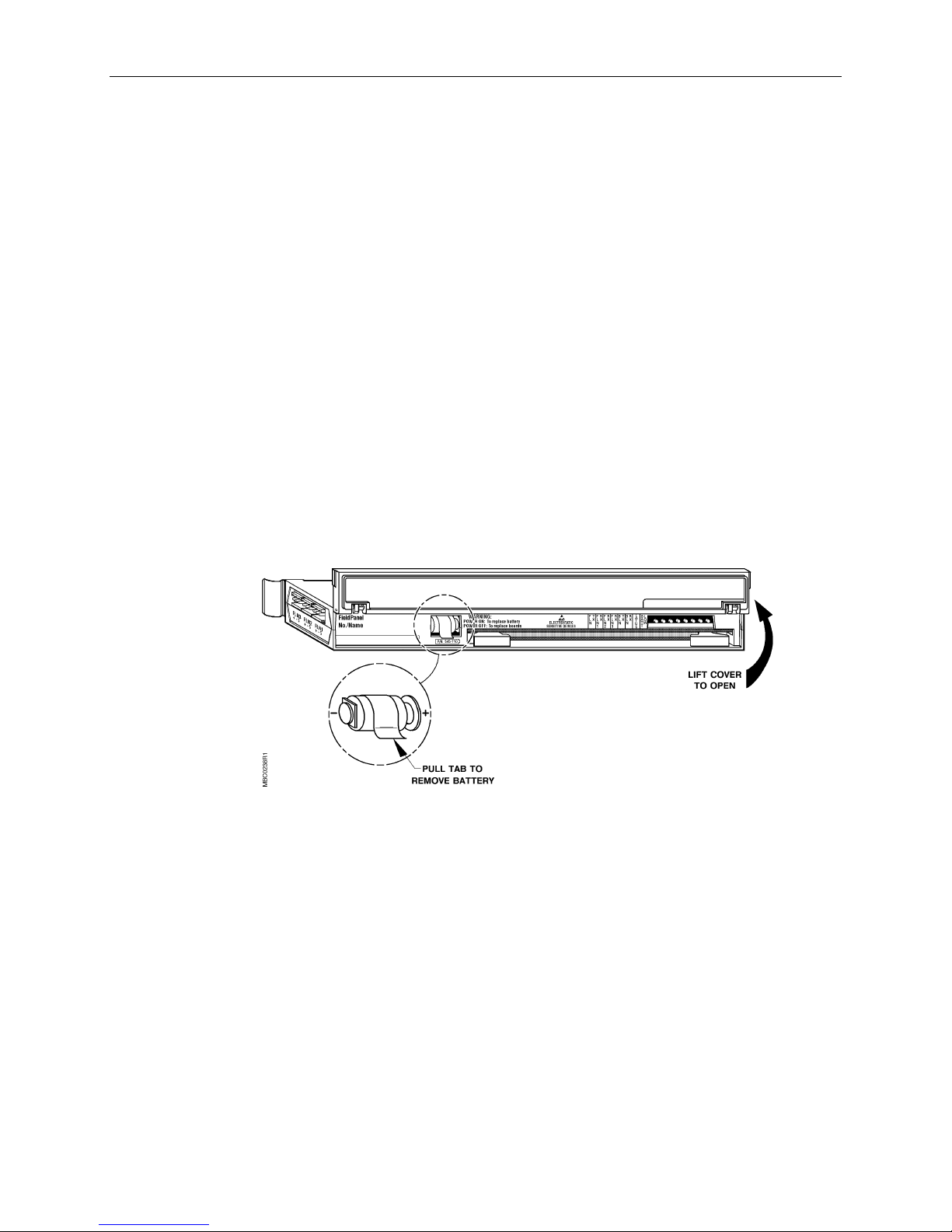
Open Processor with Trane Driver Owner's Manual
IIIInnnnsssstr
truuuuccccttttiiiion
onssss
trtr
onon
Follow these procedures to replace the battery backup of the Open Processor:
1. With the AC power to the Open Processor turned ON, lift up the front cover of the Open
Processor to expose the battery. Refer to Figure 6-1.
2. Remove the old battery from holder by pulling on the tab.
3. Properly discard the old battery and tab.
4. Insert the new battery through the loop of the new pull tab.
5. Insert the battery and pull tab combination back into the battery holder with the plus (+)
and minus (–) ends aligned as shown in Figure 6-1.
6. Close the cover of the Open Processor.
The battery replacement is complete.
FFFFiiiigu
gurrrre
gugu
e 6666----1111.
e e
. BBBBaaaatt
. .
tteeeerrrry
y RRRReeeeppppllllac
tttt
y y
aceeeemmmmen
entttt....
acac
enen
6-8 Siemens Building Technologies, Inc.
Landis Division
Page 67

GGGGllllooooss
ssaaaarrrryyyy
ssss
OOOOvvvveeeerrrrvi
aaaadd
aaaallllaaaarrrrm
aaaannnnaaaallllog
vieeeewwww
vivi
ddrrrreeeess
ss kkkkeeeeyyyy
dddd
ss ss
m pppprrrriiiioooorrrriiiittttyyyy
m m
og iiiinpu
og og
The glossary contains terms and acronyms that are used in this manual. For definitions of
point database descriptors, refer to Chapter 4
of commonly used terms as well as acronyms and abbreviations associated with the System
600 APOGEE, refer to the
(125-2185). This book is available from your local Siemens Building Technologies
representative.
PTM component that provides the PTM address for the Open Processor or Controller
Module and the point database.
The ranking of a point alarm.
nputttt----eeeelllleeeecccctr
npunpu
An analog input point that receives either a current, voltage, or resistance input signal.
triiiicccc
trtr
Technical Glossary of Building Controls Terminology and Acronyms
, Point Database
, of this manual. For definitions
aaaannnnaaaallllog ou
og outtttpu
og ouog ou
AAAASSSSHHHHRA
RAEEEE
RARA
BAC
BACne
netttt™
BACBAC
™ ((((AAAASSSSHHHHRA
nene
™ ™
putttt----pneu
pneuma
pneupneu
RAE S
RARA
mattttiiiicccc
mama
E Sttttaaaand
ndaaaarrrrd
E SE S
ndnd
d 135
135))))
d d
135135
Glossary-1
pupu
An analog output point that outputs a pneumatic signal.
American Society of Heating, Refrigeration and Air Conditioning Engineers.
The ASHRAE Building Automation and Control Networking protocol, provides mechanisms by
which computerized equipment of arbitrary function may exchange information, regardless of
the particular building service it performs. Trane has adopted a version of the BACnet
protocol as their standard protocol.
Page 68

Open Processor with Trane Driver Owner's Manual
BC
BCUUUU
BCBC
Tracer Summit Building Control Unit (BCU). The BCU communicates with the Open
Processor via RS-232 signals and provides the link between the Open Processor and the
Trane equipment controllers.
BBBBLLLLNNNN
Building level network. A data communications network providing connections within or
between buildings for building controllers and workstations. Also known as Protocol 2, P2, or
peer-to-peer network.
CCCC----BBBBuuuussss
Communications Bus. The low voltage power pathway between the Open Processor (or
Controller Module) and the Power Module.
ccccoooomma
mmand p
mmamma
CCCCon
ontr
trooooll
onon
trtr
ccccuuuurr
rren
ent
rrrr
enen
ddddiiiiggggiiiittttaaaal v
l vaaaallllue
l vl v
ddddrrrrop
op
opop
nd prrrriiiioooorrrriiiittttyyyy
nd pnd p
The ranking of a point command.
lleeeer
r Modu
Modulllleeee
llll
r r
ModuModu
Older version of the modular component that can contain the "brains" of the MBC or RBC
enclosure. The Controller Module holds the processor, memory chips, analog-to-digital
converter, supporting circuitry, and operator terminal ports. This controller module has been
replaced by the Open Processor.
t vvvvaaaallllue
ue
t t
ueue
Last commanded or sensed value of a logical point.
ue
ueue
Integer value used by the Open Processor or Controller Module to determine the logical
value, state, and the condition of logical points.
Address of an electronic device that can communicate with a field panel through a direct
connection to either the local point termination or to one of three FLN ports. When
associated with a point that has no physical device, the drop serves as an address of a
memory location for the point.
Glossary-2
Page 69

ddddyyyynnnnam
amiiiic
c po
amam
c c
en
encccclllloooossssuuuurrrreeee
enen
EEEEng
nglis
lish un
h uniiiittttssss
ngng
lislis
h unh un
EEEEnh
nhaaaannnncccced
nhnh
ed AAAAllllaaaarrrrmmmmiiiing
ed ed
Glossary
poiiiinnnnt
t iiiinnnnffffoooorrrrma
popo
t t
Information stored in the point database that may change during system operation and that is
not part of the data entered when defining points.
Metal case that houses the Open Processor and other MBC or RBC components.
The foot-pound-second system of units for weights and measurements.
Application that allows multiple alarm limits, specific alarm reporting locations, and variable
alarm limit set points.
mattttiiiion
mama
ng
ngng
on
onon
FFFFLLLLNNNN
Floor level network. A data communications network (either Protocol 1 or other vendor
protocols) providing connections within a room or building for application-specific controllers.
iiiinnnnssssttttaaaannnncccceeee
Similar to a System 600 point number.
li
litttteeeerrrraaaattttuuuurrrre po
lili
Me
Mettttaaaaddddrrrrop
MeMe
Me
Mettttaaaaddddrrrrop
MeMe
e pock
e poe po
Metal slipcase in the MBC or RBC enclosure for storing layout sheets or documentation.
op
opop
Drop 30 of FLN 3 in the System 600 point addressing scheme, used to define metadrop
points (metapoints) 00–94 for an equipment controller or device from another vendor's
system.
op PPPPooooiiiinnnntttt
op op
See
ckeeeetttt
ckck
Metapoint.
Glossary-3
Page 70

Open Processor with Trane Driver Owner's Manual
Me
Mettttaaaapo
poiiiinnnntttt
MeMe
popo
A logical point in an Open Processor that identifies an equipment controller or device and
defines the address location of its associated point.
MMMMBC
BC
BCBC
Modular Building Controller. A System 600 field panel with replaceable Open Processors, and
Power, Controller, and Point Termination Modules.
MMMM----BBBBuuuussss
Module Bus. The low voltage and communication pathway between the Open Processor or
Controller Module and the Point Termination Modules.
MMMM----BBBBuuuus
s rrrraaaail
il
s s
ilil
mmmmoun
ounttttiiiing
ng rrrraaaail
ounoun
ng ng
ob
objjjjeeeecccctttt
obob
ob
objjjjeeeecccct
t iiiidddd
obob
t t
ob
objjjjeeeecccct t
t tyyyype
t tt t
pe
pepe
obob
OOOOpen
pen PPPPrrrroooocccceeeess
pen pen
The low voltage and communication hardware pathway between the Open Processor or
Controller Module and the Point Termination Modules.
il
ilil
The hardware on which the MBC modules are installed.
Similar to a System 600 point.
Similar to a System 600 drop/equipment controller number.
Similar to a System 600 point type.
ssoooorrrr
ssss
The modular component that contains the “brains” of the MBC or RBC enclosure. The Open
Processor holds the processor, memory chips, analog-to-digital converter, supporting
circuitry, and operator terminal ports. The Open Processor is capable of supporting various
protocol drivers.
Glossary-4
Page 71

po
poiiiinnnnt
popo
po
poiiiinnnnt
popo
PPPPTTTTMMMM
RBC
RBC
RBCRBC
t ccccond
ondiiiittttiiiion
t t
ondond
t mmmmodu
odulllleeee
t t
oduodu
Glossary
on
onon
State of a point such as normal, alarm, alarm-by-command, failed or operator disabled.
Component of a PTM which provides the signal conversion between the MBC or RBC
enclosure and the field input or output point.
Point Termination Module. The interface between the Open Processor or Controller Module
and the field device.
Remote Building Controller. A System 600 field panel with replaceable Open Processors, and
Power, Controller, and Point Termination Modules.
sssseeeerrrrvi
vicccce bo
e boxxxx
vivi
e boe bo
An MBC or RBC enclosure component that receives the line power for the field panels.
tttteeeerrrrmmmmiiiinnnnaaaattttiiiion b
tttteeeexxxxtttt----bbbbaaaassssed
ttttoooottttaaaali
TTTTrrrraaaane d
ne drrrriv
ne dne d
on blllloooock
on bon b
Component of the PTM at which the field devices are terminated.
ed tttteeeerrrrmmmmiiiinnnnaaaallll
ed ed
Operator terminal which displays and accepts text only.
lized
zed vvvvaaaallllue
lili
zed zed
Sum of information (in hours or minutes) about logical points such as run time, total volume,
degree days, and so on.
iveeeerrrr
iviv
ue
ueue
ck
ckck
Software contained in the Open Processor that allows the Trane system to communicate
directly with the System 600.
unbund
unbundlllleeee
unbundunbund
Describes the action of entering a point that resides in an equipment controller's database
into the field panel's database so that it can be monitored at and/or controlled from the field
panel.
Glossary-5
Page 72

Open Processor with Trane Driver Owner's Manual
Notes
Glossary-6
Page 73

IIIInnnnde
dexxxx
dede
A
access group ................................................. 4-13
address
point ............................................................ 4-7
Alarm Management ........................................3-2
alarming......................................................... 4-13
analog point attributes ..................................4-16
Date........................................................... 4-16
Date/Time.................................................. 4-16
Float........................................................... 4-16
Integer ....................................................... 4-16
Time........................................................... 4-16
applications .....................................................5-1
Auto-Dial.......................................................... 3-2
B
BATT LOW...................................................... 2-4
battery backup ................................................ 2-4
battery replacement........................................ 6-7
product number........................................... 6-7
BLN ............................
BLN RX............................................................ 2-4
BLN TX............................................................ 2-4
building level network ..................................... 1-3
building level network
See
Daylight Savings Time .................................... 3-2
Dial-Up ............................................................ 3-2
digital point attributes
other digital point ...................................... 4-17
drop................................................................. 4-7
Duty Cycling.................................................... 3-2
E
EMER point priority ...................................... 4-10
engineering units .......................................... 4-12
Enthalpy and Dry Bulb Economizer Control.... 3-2
Equipment Controller Coordinator .................. 3-2
Expansion Module Kits ................................... 2-5
F
field equipment............................................... 2-6
field input/output points.................................. 2-6
Field Panel Coordinator................................... 3-2
FLN .................................
FLN TX............................................................ 2-4
Troubleshooting .......................................... 6-4
FLN1 RX.......................................................... 2-4
Troubleshooting .......................................... 6-4
Float attribute ............................................... 4-16
floor level network .......................................... 1-1
floor level network
See
C
C-Bus............................................................... 2-2
Change of Value (COV) limit.......................... 4-16
commanding over the network....................... 1-3
communications
troubleshooting system............................... 6-7
compatibility .................................................... 1-2
control program
execution of................................................. 1-2
control strategy ............................................... 1-1
Controller module
in cabinet with Open Processor ..................2-3
Controller Module ...........................................2-5
D
Database
point address............................................... 4-7
Date attribute ................................................4-16
Date/Time attribute .......................................4-16
G
gathering and processing field inputs ............. 1-2
I
Integer attribute ............................................ 4-16
L
LAO point...................................................... 4-17
LEDs ............................................................... 2-4
literature pocket.............................................. 2-7
Local Area Network (LAN) Controller.............. 1-2
local points............................................... 4-2, 4-3
Logical Analog Input (LAI) point ...................... 4-2
Logical Analog Output (LAO) point ................. 4-2
Logical Digital Input (LDI) point ....................... 4-2
Logical Digital Output (LDO) point .................. 4-2
Logical ENUMerated (LENUM) point..... 4-2, 4-15
logical points ................................................... 4-2
types of ....................................................... 4-2
Index-1
Page 74

Open Processor with Trane Driver Owner’s Manual
Loop Tuning ....................................................3-2
M
MBC..................
M-Bus.......................................
Metadrops..................................................... 4-18
MMI/modem port ........................................... 2-7
communication speed of............................. 2-7
modem............................................................ 2-7
Modular Building Controller............................. 2-2
compatibility ................................................1-2
Modular Bus.................................................... 2-5
Modular Building Controller
See
Modular Bus
See
N
naming conventions ........................................ 4-5
NONE point priority.............................. 4-10, 4-11
O
Open Processor
applications.................................................. 5-1
battery backup............................................. 2-4
connections ................................................. 2-4
description................................................... 2-3
LEDs............................................................ 2-4
memory .......................................................1-3
multiple Open Processors and/or Controller
Modules in one enclosure ....................... 2-3
operation of .................................................1-1
other ............................................................ 2-5
remote sites ................................................1-3
software ......................................................3-1
troubleshooting ...........................................6-2
OPER point priority ..............................4-10, 4-11
operator commands........................................ 1-2
operator interface..................................... 2-6, 3-2
operator terminals ........................................... 2-6
Other Open Processors ..................................2-5
P
P2...............................
parts, ordering replacement............................ 6-2
PDL point priority ................................. 4-10, 4-11
Peak Demand Limiting (PDL) .......................... 3-2
peer-to-peer network .
physical point address................................... 4-15
physical points ................................................ 4-2
slope and intercept constants ................... 4-17
point address .........................................4-7, 4-14
drop ............................................................. 4-7
point alarming................................................ 4-13
building level network
See
building level network
See
point attributes ............................................. 4-12
access group ............................................. 4-13
Change of Value (COV) limit...................... 4-16
engineering units....................................... 4-12
other analog point attributes ..................... 4-16
other digital point ...................................... 4-17
point address ............................................ 4-14
point alarming............................................ 4-13
point descriptor ......................................... 4-12
point name ................................................ 4-12
point totalization ........................................ 4-14
point type .................................................. 4-12
state .......................................................... 4-15
point characteristics........................................ 4-3
point database ................................................ 4-1
point naming conventions ........................... 4-5
point descriptor............................................. 4-12
point name............................................. 4-4, 4-12
Point operation
troubleshooting ........................................... 6-5
point priority.................................................. 4-10
EMER ........................................................ 4-10
NONE ............................................... 4-10, 4-11
OPER................................................ 4-10, 4-11
PDL .................................................. 4-10, 4-11
SMOKE ..................................................... 4-10
point states ................................................... 4-11
point status ..................................................... 4-8
point system name......................................... 4-4
Point Termination Modules...................... 2-3, 2-6
troubleshooting ........................................... 6-5
point totalization............................................ 4-14
point type...................................................... 4-12
point values................................................... 4-11
points
local ...................................................... 4-2, 4-3
logical .......................................................... 4-2
naming conventions .................................... 4-5
physical ....................................................... 4-2
virtual.................................................... 4-2, 4-3
Power LED...................................................... 6-5
Power Module ......................................... 2-3, 2-5
Powers Process Control Language................. 3-2
PPCL ......
Primary Module .............................................. 2-6
printer
alarm ........................................................... 1-3
priority
point .......................................................... 4-10
Protocol 2...................
PTM ...................
Powers Process Control Language
See
building level network
See
Point Termination Modules
See
Index-2
Page 75

Index
R
RBC....................
Remote Building Controller ............................. 2-2
compatibility ................................................1-2
operation of .................................................1-2
replacement parts, ordering............................ 6-2
RS-232 port .....................................................2-7
Remote Building Controller
See
S
slope and intercept constants....................... 4-17
SMOKE point priority .................................... 4-10
Stand-alone Control Unit (SCU)....................... 1-2
Start/Stop Time Optimization.......................... 3-2
state .............................................................. 4-15
STATUS........................................................... 2-4
STATUS LED............................................ 6-1, 6-3
status lights
Open Processor........................................... 2-4
system configuration ......................................2-1
T
thermistors ................................................... 4-16
Time attribute ............................................... 4-16
Time-Of-Day (TOD) Scheduling....................... 3-2
Totalize.......................................................... 4-14
Trend Data Collection ..................................... 3-2
troubleshooting............................................... 6-2
battery replacement .................................... 6-7
Open Processor .......................................... 6-2
Point Termination Modules ......................... 6-5
points .......................................................... 6-5
system communications............................. 6-7
V
video display terminals ................................... 2-7
virtual point address ..................................... 4-15
virtual points ............................................ 4-2, 4-3
slope and intercept constants ................... 4-17
Index-3
Page 76

Open Processor with Trane Driver Owner’s Manual
Notes
Index-4
 Loading...