

Siemens OpenAir GDE161.1T, OpenAir GLB, OpenAir GDE161.1T/B, OpenAir GLB161.1P, OpenAir GDE163.1P Technical Instructions
...
Technical Instructions
Document No. 155-187P25
EA GDE/GLB-1
November 30, 2005
OpenAir™ Electric Damper Actuators
GDE/GLB Series
Non-spring Return Rotary
24 Vac - Modulating Control 0 to 10 Vdc
Description
Features
Application
The OpenAir direct coupled 24 Vac non-spring return rotary electri c actu ators are designed
for modulating control of dampers.
• Compact, lightweight design
• Self-adapting capability for maximum flexibility in damper positioning
• Manual override
• Offset and slope adjustment models available
• Independently adjustable dual auxiliary switches available
• cUL and UL listed;
These actuators are used in constant or variable air volume installations for control of HVAC
dampers requiring up to 44 lb-in (5 Nm) or 88 lb-in (10 Nm) of torque.
certified
Product Numbers
Table 1. 24 Vac Operating Voltage.
Torque Cabling Standard
GDE161.1P Plenum
GDE161.1P/B
44 lb-in (5 Nm)
Terminal Strip
88 lb-in (10 Nm) Plenum GLB161.1P GLB163.1P GLB164.1P GLB166.1P
(24 pk)
GDE161.1T — — —
GDE161.1T/B
(24 pk)
Slope/Offset
Adjustable
GDE163.1P GDE164.1P GDE166.1P
— — —
Dual Auxiliary
Switches and
Slope/Offset
Adjustable
Dual Auxiliary
Switches
Siemens Building Technologies, Inc.
Only

Technical Instructions OpenAir Non-Spring Return Rotary Electric Damper Actuator
Document Number: 155-187P25 24 Vac – Modulating Control
November 30, 2005
Specifications
Operating voltage (G–G0) 24 Vac +20%, -15%
Frequency 50/60 Hz
Power Supply
Control signal
Power consumption 3.3 VA
Input signal (Y-G0)
Voltage-input 0 to 10 Vdc
Input resistance 100K ohms
Feedback signal
Position output signal (U–G0)
Voltage-output 0 to 10 Vdc
Maximum output current DC 1 mA
Equipment rating
Rating: Class 2 according to UL, CSA
Class III per EN60730
Auxiliary features
Control signal adjustment
Offset (start point) Between 0 to 5 Vdc
Slope (span) Between 2 and 30 Vdc
Dual auxiliary switch contact rating 4A resistive, 2A inductive
Voltage 24 Vac/24 Vdc
DC rating 12 to 30 Vdc
DC 2A
Switch Range
Switch A 0 to 90° with 5° intervals
Recommended range usage 0 to 45 °
Factory setting 5°
Switch B 0 to 90° with 5° intervals
Recommended range usage 45° to 90°
Factory setting 85°
Switching hysteresis: 2°
Function
Torque
GDE 44 lb-in (5 Nm)
GLB 88 lb-in (10 Nm)
Runtime for 90° opening or closing
GDE 90 sec. at 60 Hz (108 sec. at 50 Hz)
GLB 125 sec. at 60 Hz (150 sec. at 50 Hz)
Nominal angle of rotation 90°
Maximum angular rotation 95°
Mounting
Shaft size: Minimum shaft length 3/4-inch (20 mm)
3/8 to 5/8 inch
EA1010R1
8 -16 mm
1/4 to 1/2 inch
6 - 12.7 mm
9/16 inch
15 mm
Figure 1. Acceptable Shaft Sizes.
Page 2 Siemens Building Technologies, Inc.

OpenAir Non-Spring Return Rotary Electric Damper Actuator Technical Instructions
24 Vac – Modulating Control Document Number: 155-187P25
November 30, 2005
Specifications, continued
Housing
Ambient conditions
Agency certification
conformity
Miscellaneous
Enclosure: NEMA Type 2
IP54 according to EN60529
Material: Durable plastic
Gear lubrication: Silicone-free
Ambient temperature
Operation: -25°F to 130°F (-32°C to 55°C)
Storage and transport: -40°F to 158°F (-40°C to 70°C)
Ambient humidity (non-condensing): 95% rh
UL listed to UL873
cUL certified to Canadian
Standard C22.2 No. 24-93
In accordance with the directive set forth by the European Union for
Electromagnetic Compatibility (EMC): 89/336/EEC
Emissions standards: EN 50081-1
Immunity standards: EN 50082-2
Pre-cabled connection: 18 AWG
Cable length: 3 feet (0.9m)
Life cycle: Designed for over 60,000 full
strokes and a minimum of 1.5
million repositions at rated torque
and temperature
Dimensions: See
Figure 22
Weight: 1.06 lb (0.48 kg)
Siemens Building Technologies, Inc. Page 3
Technical Instructions OpenAir Non-Spring Return Rotary Electric Damper Actuator
Document Number: 155-187P25 24 Vac – Modulating Control
November 30, 2005
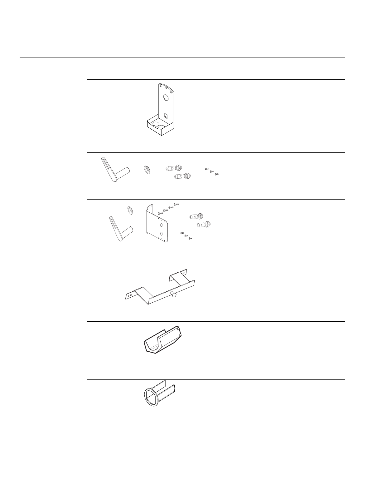
Accessories
NOTE: The auxiliary switches cannot be added in the field. Order the product number that
includes this option. See Table 1.
ASK76.1U Provides connection
between the actuator and conduit.
EA0647R1
Figure 2. Conduit adapter.
ASK71.5 Allows a direct-coupled
actuator to provide an auxiliary linear
drive.
EA0695R1
Figure 3. Rotary to linear.
ASK71.6 Allows economical mounting
of an OpenAir actuator to a variety of
surfaces.
Ea0696R1
Figure 4. Rotary to linear with bracket.
Should be used in applications where
the actuator can be rigid-surface
mounted and a linear stroke output is
needed.
ASK73.1 Bracket provides extended
anti-rotation pin allowing two OpenAir
actuators to directly drive a single
EA0496R1
Figure 5. Tandem Mount Bracket.
damper shaft. For use with two- and
three-position actuators.
ASK78.3U Shaft insert for use with 3/8inch (8 to 10 mm) diameter shafts.
(10/pk). Included in box with GDE/GLB
series.
EA0807R1
NOTE: Factory-installed 1/2-inch
Figure 6. Shaft insert.
guide must be removed prior
to installation.
985-101P25:
Shaft guide, 1/2-inch (25/pk). Factory
installed with GDE/GLB Series.
EA1060R1
Figure 7. 1/2-inch Shaft Guide.
Page 4 Siemens Building Technologies, Inc.
OpenAir Non-Spring Return Rotary Electric Damper Actuator Technical Instructions
24 Vac – Modulating Control Document Number: 155-187P25
November 30, 2005
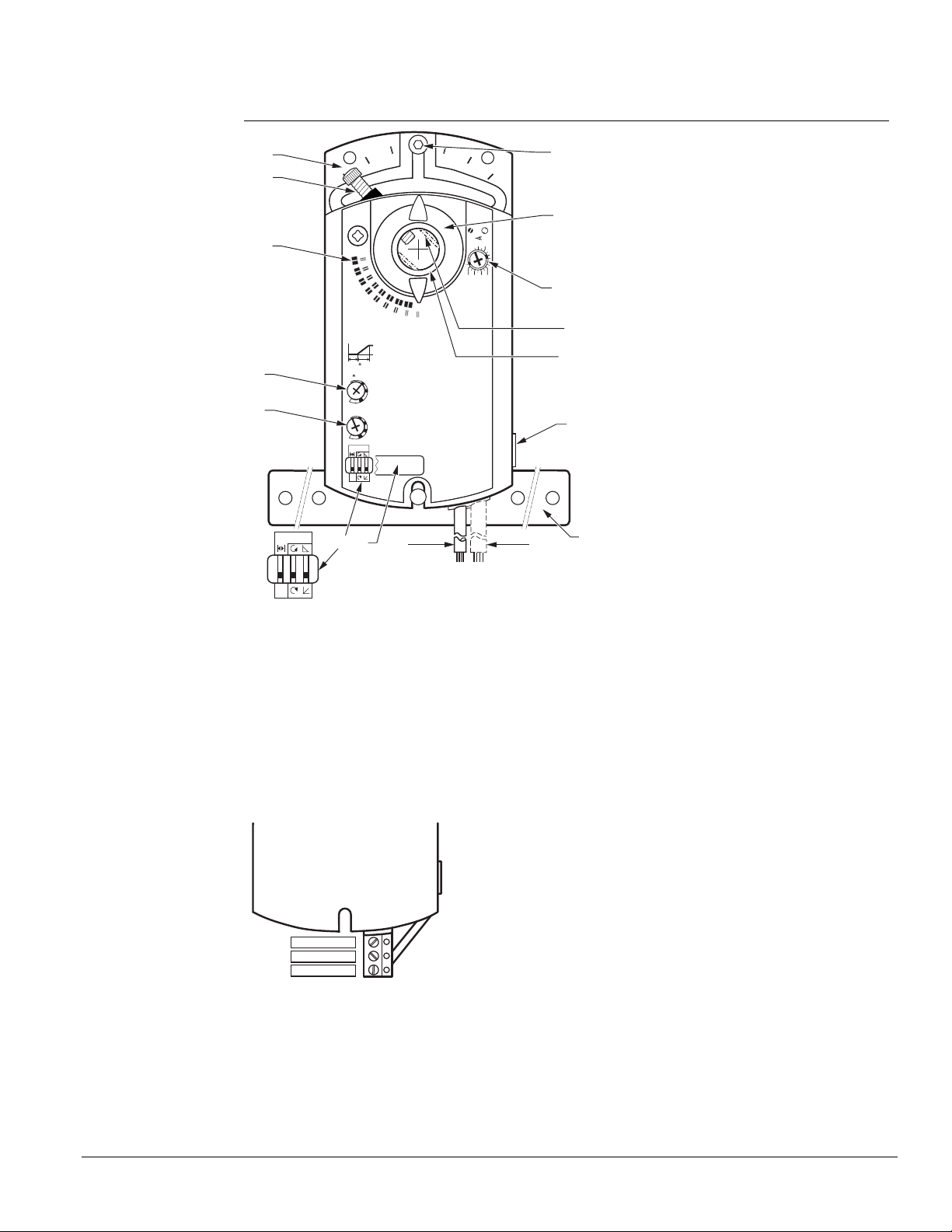
Actuator
Components
15
1
16
Legend
1. Base plate
2. Positioning scale for angle of
14
A B
80 70 60
Aux Switch
Adjustment
2010
50
12,13
2
90
45
90
11
Ys
U
Uo
V
3
4
2
30
0
5
self adapt
U
10
16
24
Uo
1
2
3
4
10
9
rotation
3. Slope adjustment
4. Offset (start point) adjustment
5. DIP switches
6. Cover for DIP switches
7. Connection cables
8. Connection cables
9. Manual override
self adapt
0
EA0641R3
0
5
6
78
Figure 8. Parts of the Actuator.
GDE161.1T
10. Coupling bushing
11. Factory installed 1/2-inch guide
12. Auxiliary switch A
17
13. Auxiliary switch B
14. Position indicator
15. Adjustment lever with locking screw
(4 mm hex)
16. Set screw for mechanical range
stop (4 mm hex)
17. Mounting bracket
GDE161.1T
This model uses a terminal strip for
connection purposes rather than cable
connections (7,8).
COM
0 to 10 Vdc Input
EA1093R1
Supply 24 Vac
Figure 9. Special Features of Terminal Strip Model.
Siemens Building Technologies, Inc. Page 5
 Loading...