

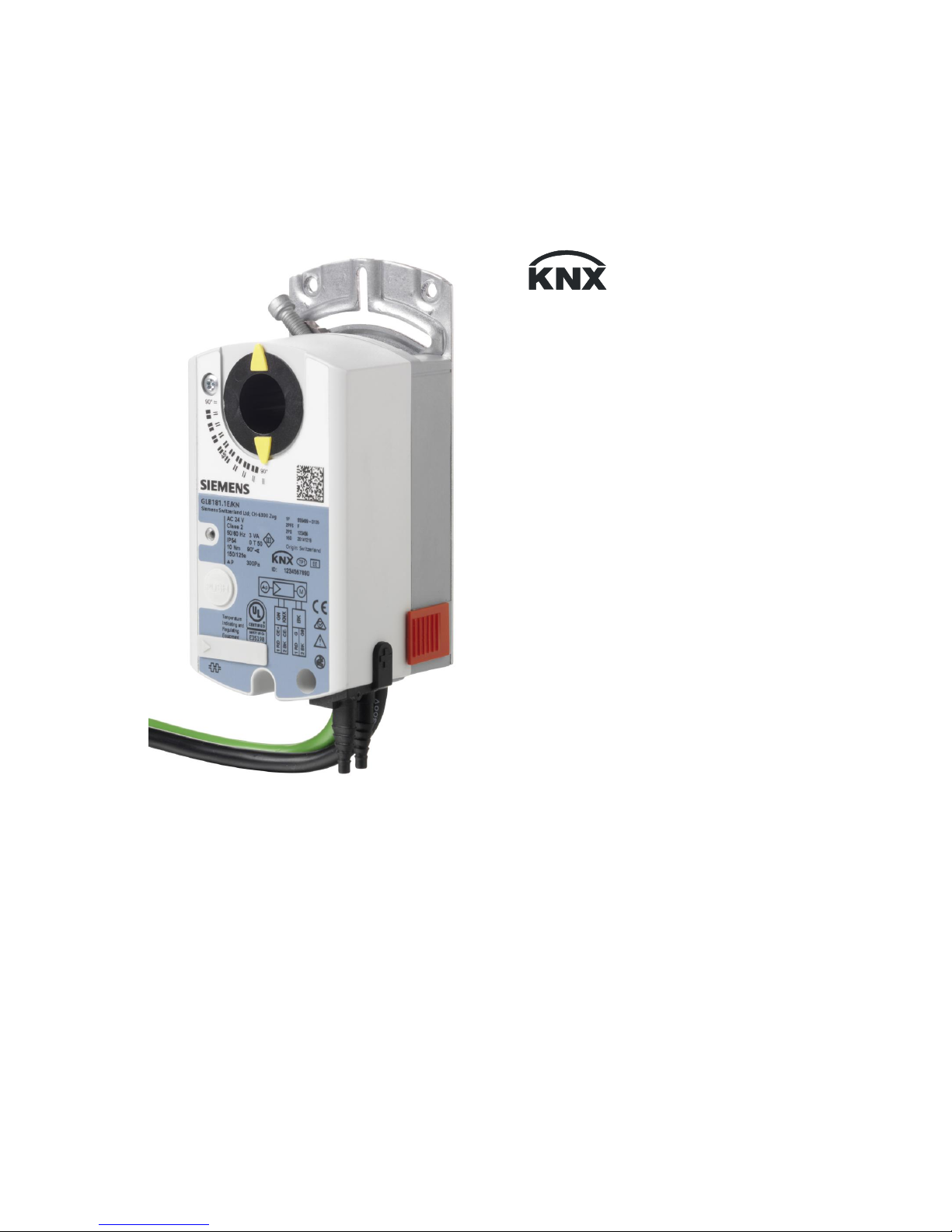
Siemens OpenAir G..B181.1E/KN Series, OpenAir GDB181.1E/KN, OpenAir GLB181.1E/KN Technical Basics
s
OpenAir
T
M
VAV compact controller KNX/PL-Link G..B181.1E/KN
Technical Basics
CE1P3547en
2017-03-23 Building Technologies

2 / 44
Siemens VAV compact controller KNX/PL-Link G..B181.1E/KN CE1P3547en
Building Technologies 2017-03-23
Issued by
Siemens Switzerland Ltd
Building Technologies Division
International Headquarters
Gubelstrasse 22
6301 Zug
Switzerland
Tel. +41 41-724 24 24
www.siemens.com/buildingt echnologies
© Siemens Switzerland Ltd, 2017
Technical specifications and availability subject to change without notice.

3/44
Siemens VAV compact controller KNX/PL-Link G..B181.1E/KN CE1P3547en
Building Technologies 2017-03-23
Table of contents
1 Introduction.......................................................................................... 5
1.1 Revision history ..................................................................................... 5
1.2 Before you start ..................................................................................... 5
1.2.1 Trademarks ........................................................................................... 5
1.2.2 Copyright ............................................................................................... 5
1.2.3 Quality assurance .................................................................................. 5
1.2.4 Document use / request to the reader .................................................... 5
1.3 Objectives of this basic documentation................................................... 6
1.4 Abbreviations and naming conventions .................................................. 6
1.4.1 Abbreviations ......................................................................................... 6
1.4.2 Naming conventions .............................................................................. 6
1.5 References ............................................................................................ 7
2 Device ................................................................................................... 8
2.1 Type summary ....................................................................................... 8
2.1.1 Device variants, tools and accessories ................................................... 8
2.1.2 Selection guide for all types ................................................................. 10
2.1.3 Version summary ................................................................................. 11
2.2 Design and device parts....................................................................... 12
2.3 Dimensions .......................................................................................... 12
2.4 Human-machine interface .................................................................... 13
2.5 Internal diagrams ................................................................................. 14
2.6 Measuring principle .............................................................................. 15
3 Functionality / application ................................................................. 16
3.1 Fields of application ............................................................................. 16
3.2 Equipment combinations ...................................................................... 16
3.3 Application examples ........................................................................... 17
3.3.1 Application example 1: Supply air control ............................................. 17
3.3.2 Application example 2: Supply and extract air control ........................... 17
3.3.3 Application example 3: AHU optimization ............................................. 18
3.4 Further application examples ............................................................... 19
3.4.1 Application examples for Synco 700 (Series C or newer)...................... 19
3.4.2 Application examples for Desigo Total Room Automation ..................... 19
4 Electrical and mechanical installation .............................................. 20
4.1 Mechanical installation / mounting ........................................................ 20
4.2 Electrical installation / cabling .............................................................. 21
4.2.1 Power supply cabling ........................................................................... 21
4.2.2 Bus cabling .......................................................................................... 22
5.3 Setting examples ................................................................................. 26
5.3.1 Symbols and parameters ..................................................................... 26
5.3.2 Min/max control by the supervisory controller ....................................... 26
5.3.3 Min/max control by the VAV compact controller .................................... 28
5.3.4 Master/Slave operating mode .............................................................. 30
6 Engineering and commissioning ...................................................... 32
6.1 Fundamentals ...................................................................................... 32
6.1.1 System environments .......................................................................... 32

4/44
Siemens VAV compact controller KNX/PL-Link G..B181.1E/KN CE1P3547en
Building Technologies 2017-03-23
6.1.2 Documentation of engineering and commissioning ............................... 32
6.1.3 Address labels ..................................................................................... 32
6.2 Engineering ......................................................................................... 33
6.2.1 KNX S-mode engineering .................................................................... 33
6.2.2 KNX LTE-mode / Synco 700 engineering ............................................. 33
6.2.3 Desigo PL-Link / Desigo PXC3.. engineering ....................................... 34
6.3 Commissioning .................................................................................... 35
6.3.1 Preconditions ....................................................................................... 35
6.3.2 KNX S-mode commissioning................................................................ 36
6.3.3 KNX LTE-mode commissioning ............................................................ 36
6.3.4 PL-Link commissioning ........................................................................ 36
7 Safety and EMC optimization ............................................................ 37
7.1 Safety notes ........................................................................................ 37
7.2 Device-specific regulations .................................................................. 38
7.3 Notes on EMC optimization .................................................................. 39
8 Technical data .................................................................................... 40
9 Parameters and datapoints ............................................................... 41
9.1 Parameter description .......................................................................... 41
9.2 Device parameters (ACS931 / ACS941 / AST20) ................................. 42
9.3 Parameters for engineering tools ......................................................... 42
9.4 S-mode datapoints............................................................................... 43
10 Environmental compatibility and disposal ....................................... 44
5/44
Siemens VAV compact controller KNX/PL-Link G..B181.1E/KN CE1P3547en
Building Technologies 2017-03-23
1 Introduction
1.1 Revision history
1.2 Before you start
1.2.1 Trademarks
Trademarks used in this document are listed together with their legal owners below.
Use of these trademarks is subject to international and national statutory provisions.
Trademarks
Legal owner
KNX® KNX Association, B - 1831 Brussels-Diegem Belgium
http://www.knx.org/
All the product names listed are trademarks (™) or registered trademarks (®) of
their respective owners, as listed in the table. Further to the notes in this section,
and to facilitate the reading of the text, these trademarks will not be indicated
elsewhere in the text (e.g. by use of symbols such as ® or ™).
1.2.2 Copyright
This document may be duplicated and distributed only with the express permission
of Siemens, and may be passed only to authorized persons or companies with the
required technical knowledge.
1.2.3 Quality assurance
These documents were prepared with great care.
∂ The contents of all documents are checked at regular intervals.
∂ Any corrections necessary are included in subsequent versions.
∂ Documents are automatically amended as a consequence of modifications and
corrections to the products described.
Please make sure that you are aware of the latest document revision date.
If you find lack of clarity while using this document, or if you have any criticisms or
suggestions, please contact your local point of contact in your nearest branch
office. The addresses of the Siemens regional companies are available at
www.siemens.com/sbt.
1.2.4 Document use / request to the reader
Before using our products, it is important that you read the documents supplied
with or ordered at the same time as the products (equipment, applications, tools
etc.) carefully and in full.
We assume that persons using our products and documents are authorized and
trained appropriately and have the technical knowledge required to use our
products as intended.
More information on the products and applications is available:
Version
Date
Changes
Section
Pages
2.0 23.03.2017 Update for Series G
1.0 26.02.2016 EU and RCM Conformity,
European Directive 2012/19/EU
8 Technical data,
10 Environmental
compatibility and disposal
38
42
6/44
Siemens VAV compact controller KNX/PL-Link G..B181.1E/KN CE1P3547en
Building Technologies 2017-03-23
∂ On the intranet (Siemens employees only) at
https://workspace.sbt.siemens.com/content/00001123/default.aspx
∂ From the Siemens branch office near you www.siemens.com/sbt or from your
system supplier
∂ From the support team at headquarters fieldsupport-zug.ch.sbt@siemens.com
if there is no local point of contact
Siemens assumes no liability to the extent allowed under the law for any losses
resulting from a failure to comply with the aforementioned points or for the
improper compliance of the same.
1.3 Objectives of this basic documentation
This basic documentation covers the networked VAV compact controllers
GDB181.1E/KN and GLB181.1E/KN. These devices are designed for controlling
variable or constant air volume flows.
This document is structured along the according workflow. Following a description
of the devices and their application, mounting, engineering, and commissioning are
covered. A references section lists technical data, parameters, and data points.
1.4 Abbreviations and naming conventions
1.4.1 Abbreviations
Abbreviation
Description
Desigo TRA Total Room Automation (Part of Desigo V5)
ABT Automation Building Tool – part of Desigo XWP
SSA Setup and Service Assistant
LTE Logical Tag Extended (KNX Mode)
USS Universal Serial Interface Protocol (industry automation protocol)
VSD Variable Speed Drive
1.4.2 Naming conventions
Throughout this documentation the term “VAV compact controller(s)” refers to the
GDB181.1E/KN as well as to the GLB181.1E/KN.

7/44
Siemens VAV compact controller KNX/PL-Link G..B181.1E/KN CE1P3547en
Building Technologies 2017-03-23
1.5 References
[1] G..B181.1E/KN – Datasheet for VAV compact controller (N3547)
[2] G..B181.1E/KN – Mounting instruction for VAV compact controller (M3547)
[3] AST20 – Handheld tool for VAV compact controller (A6V10631836)
[4] AST11 – Interface converter (N5852)
[5] ACS931 – PC-Software for OEM (N5853)
[6] ACS941 – PC-Software for Service (N5854)
[7] Scan-to-HIT App for iOS devices (link)
[8] Scan-to-HIT App for Android devices (link)
[9] Desigo V5 Basic manual, chapter 21 “Room automation”
[10] Desigo XWP (ABT Online help)
[11] Desigo TRA Setup and Service Assistant (SSA) (CM111050en)
[12] Desigo TRA mounting and installation manual (CM111043en)
[13] Synco Communication over KNX Bus – Basic documentation (P3127)
[14] Synco 700 Universal controller RMU710B, RMU720B, RMU730B (P3150)
[15] Synco planning and commissioning protocol V2.6 (C3127)
[16] Synco KNX S-Mode datapoints (Y3110)
8 / 44
Siemens VAV compact controller KNX/PL-Link G..B181.1E/KN CE1P3547en
Building Technologies 2017-03-23
2 Device
2.1 Type summary
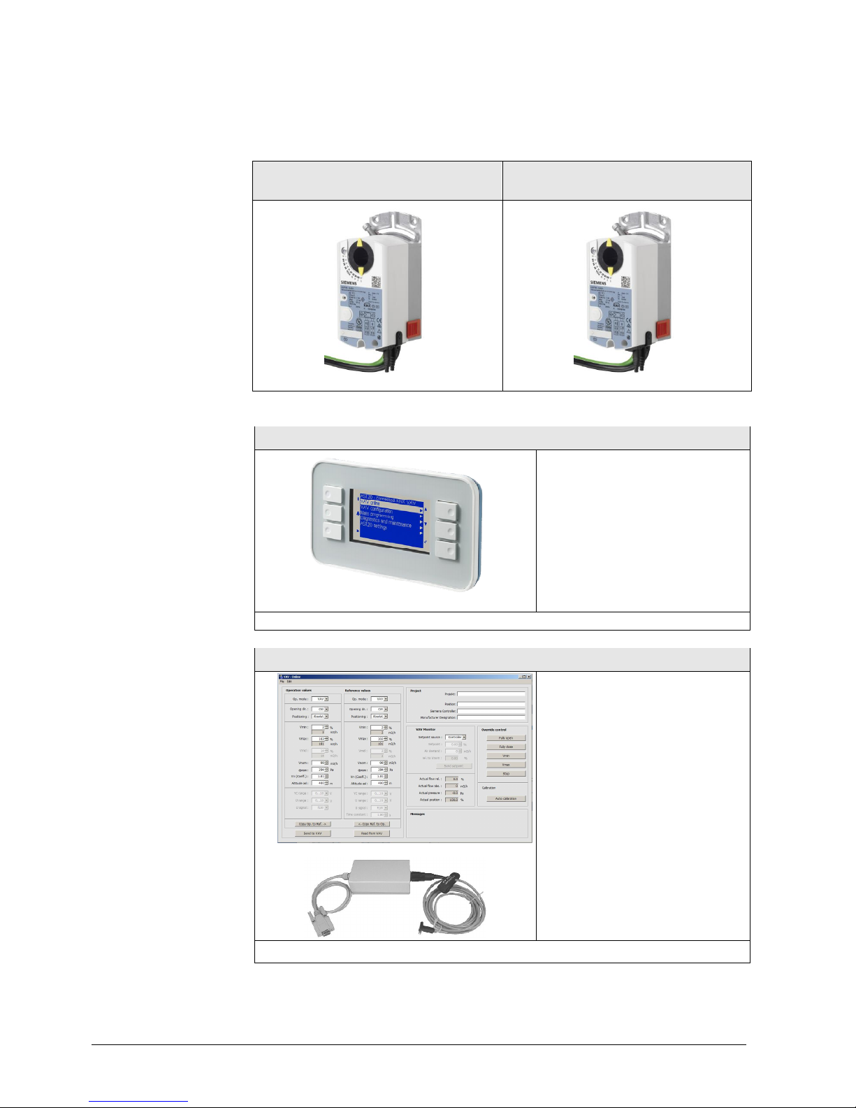
2.1.1 Device variants, tools and accessories
GDB181.1E/KN (5 Nm) GLB181.1E/KN (10 Nm)
AST10
The handheld tool AST20 can be
used to set the VAV and actuator
parameters and supports access
levels for service technicians and
OEMs.
Datasheet: A6V10631836
ACS941 / AST11
The PC software for service
ACS941 can be used for setting
and reading a certain set of device
parameters (values set by OEM
and current configuration, and
actual values), cf. section 9.2.
For connecting to a PC with
RS232 interface, an interface
converter AST11 is required.
Datasheet: N5852
VAV compact controller
KNX/PL-Link
Tools for
commissioning and
service

9 / 44
Siemens VAV compact controller KNX/PL-Link G..B181.1E/KN CE1P3547en
Building Technologies 2017-03-23
Scan
-to-
HIT App
The Scan-to-Hit App can be used to
retrieve technical information about
the actuator by scanning the DMC
(data matrix code) in the top right
corner of the actuator.
The app can be obtained free of charge at [7] resp. [8]
For information regarding accessories and spare parts for VAV compact controllers,
please refer to datasheet N4698.
Accessories
10 / 44
Siemens VAV compact controller KNX/PL-Link G..B181.1E/KN CE1P3547en
Building Technologies 2017-03-23
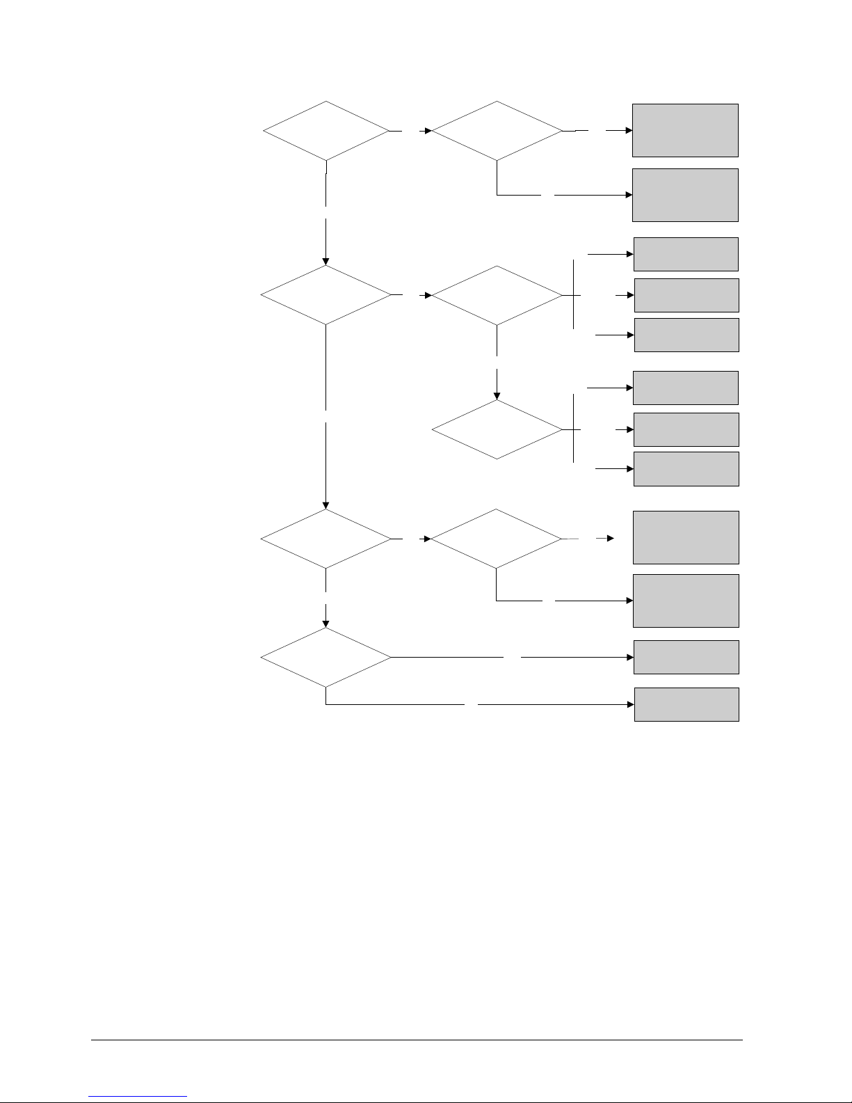
2.1.2 Selection guide for all types
Spring return
function?
Actuator >10 Nm
Actuator >5 Nm
Auxiliary switch
GLB181.1E /3
10 Nm
GDB181.1E/3
5 Nm
GDB181.1E/MO
5 Nm
ASV181.1E/3
with 3P actua tor
GMA131.1E (7 Nm )
GCA131.1E (18 Nm)
ASV181.1E/3
with 3P actuator
GMA136.1E (7 Nm )
GCA136.1E (18 Nm)
ASV181.1E/3
with 3P actuator
GEB136.1E ( 15 Nm)
GBB136.1E ( 25 Nm)
GLB136.1E (35 Nm)
ASV181.1E/3
with 3P actuator
GEB131.1E ( 15 Nm)
GBB131.1E ( 25 Nm)
GLB131.1E (35 Nm)
Bus conn ection
Actuator <=10 Nm
and >5 Nm
Actuator <=5 Nm
Yes
No
No
No
Yes
Yes
No
No
Yes
Yes Auxiliary switch
No
Yes
Modbus
No
GDB181.1E/BA
5 Nm
BACnet
GDB181.1E/KN
5 Nm
KNX
GLB181.1E/MO
10 Nm
Modbus
GLB181 .1E/BA
10 Nm
BACnet
GLB181 .1E/KN
10 Nm
KNX
11 / 44
Siemens VAV compact controller KNX/PL-Link G..B181.1E/KN CE1P3547en
Building Technologies 2017-03-23
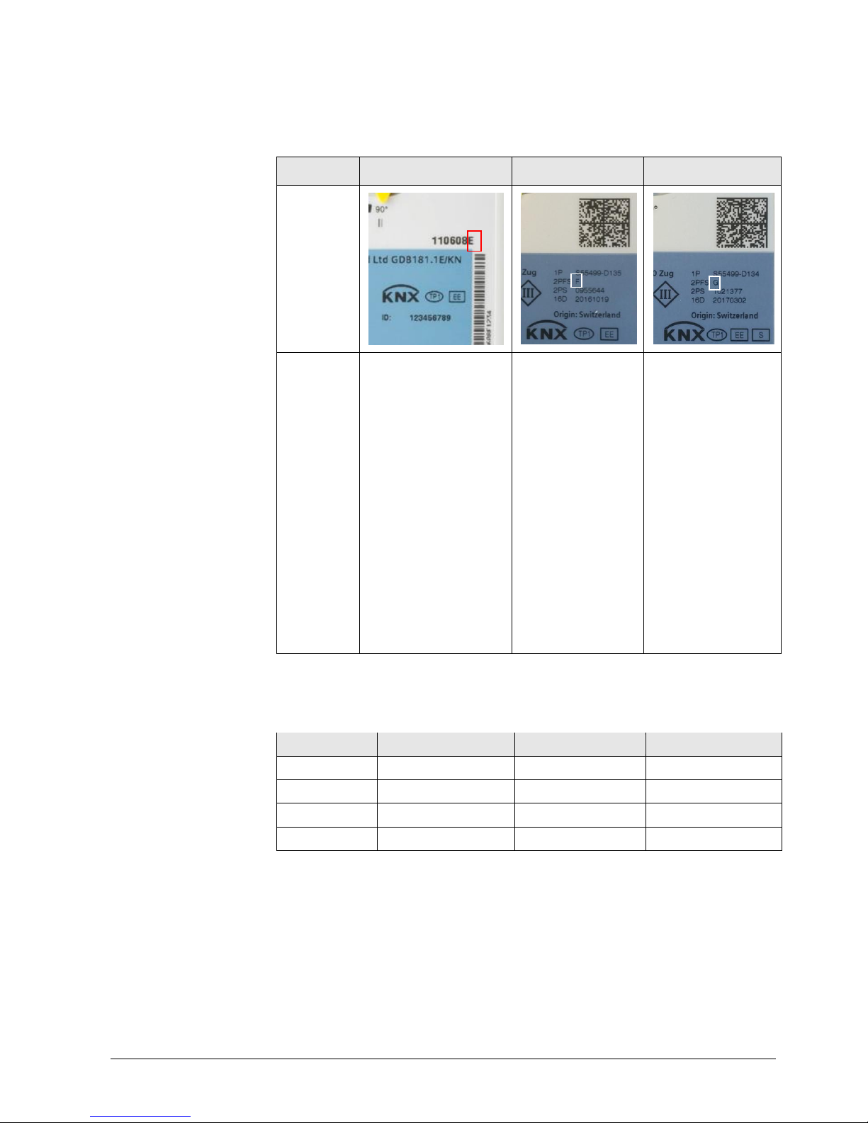
2.1.3 Version summary
Series identification and actuator data can be found in the top right corner of the
product label. As of Series F, the device data is also stored in a DMC (data matrix
code) in the top right corner. It can be read out with any QR Code / DMC scanner
or the Scan-to-HIT app available at ([7] resp. [8]).
VAV Compact Controllers series G are designed for using ETS device profile v2.x,
however ETS device profile v1.x is supported for backward compatibility reasons.
Version
Series E
Series F
Series G
Production period 10/2011 – 03/2014 03/2014 – 01/2017 01/2017
FW version 4.16 4.18 4.24
ETS profile v1.x supported supported supported
ETS profile v2.x not supported not supported supported
Version identification
Version Series E Series F Series G
Identification
Features
∂ Communication over
Desigo PL-Link or
KNX (LTE- and Smode).
∂ New differential
pressure sensor.
∂ Simultaneous
feedback of actual
values of damper
position and air
volume flow.
∂ Optional adaptive
opening range
measurement
(adaptive positioning).
∂ HMI with push button
and LED.
∂ Stability
Improvements
∂ Support for DMC
(data matrix code)
based workflows
∂ Improved ETS and
Desigo ABT
interfaces
Compatibility
12 / 44
Siemens VAV compact controller KNX/PL-Link G..B181.1E/KN CE1P3547en
Building Technologies 2017-03-23
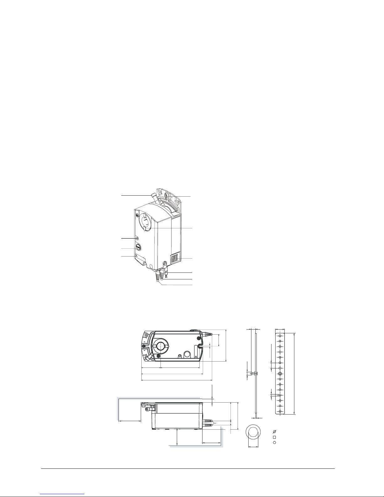
2.2 Design and device parts
The VAV compact controllers consist of a differential pressure sensor, actuator and
digitally configurable control electronics. They are intended for mounting on
damper shafts of a minimum length of 30 mm. They consist of base and 2-sectional
housing.
Components contained in the base:
∂ Steel base plate with damper drive shaft fixing for different drive shaft
diameters / cross-sectional areas (cf. section 2.3) and angular rotation limiter,
∂ maintenance-free, low-noise gear train,
∂ magnetic hysteresis clutch with practically contact-free force transmission; this
means that the actuator is locking- and overload-proof, also in continuous
operation.
Components contained in the housing (Note: the housing cover must not be
removed):
∂ Controller electronics,
∂ differential pressure sensor,
∂ synchronous motor for the damper actuator.
1 Shaft attachment screw
2 LED
3 Push button
4 Configuration and maintenance interface (below c over)
5 Connection nozz le f or m
easuring differential pressure in
the VAV box
6
Connection nozzle for measuri ng differential pressure in
the VAV box ("+": Side with higher pressure)
7 Two connecting cables (power and communications),
2-c ore each
8 Dis engagement of gear train
9 Rotation angle display
10 Rotation angle check screw
Manual control of the air dampers is possible by gear train disengagement (8)
when the VAV compact controller is disconnected from the power supply.
2.3 Dimensions
min. 100
min.
200
min. 80
min. 6
8
20
ø7
2
5
180
X
8 - 16 mm
12.8 mm
15 mm
3547M01
14 x 12
X =
4.15
71
26.5
87
158
137
Ø 3.. .8
43
41.3
61
9.6
Measures in mm
2
3
4
5
8910
3547J01
617
Main device parts
Gear train
disengagement
13 / 44
Siemens VAV compact controller KNX/PL-Link G..B181.1E/KN CE1P3547en
Building Technologies 2017-03-23
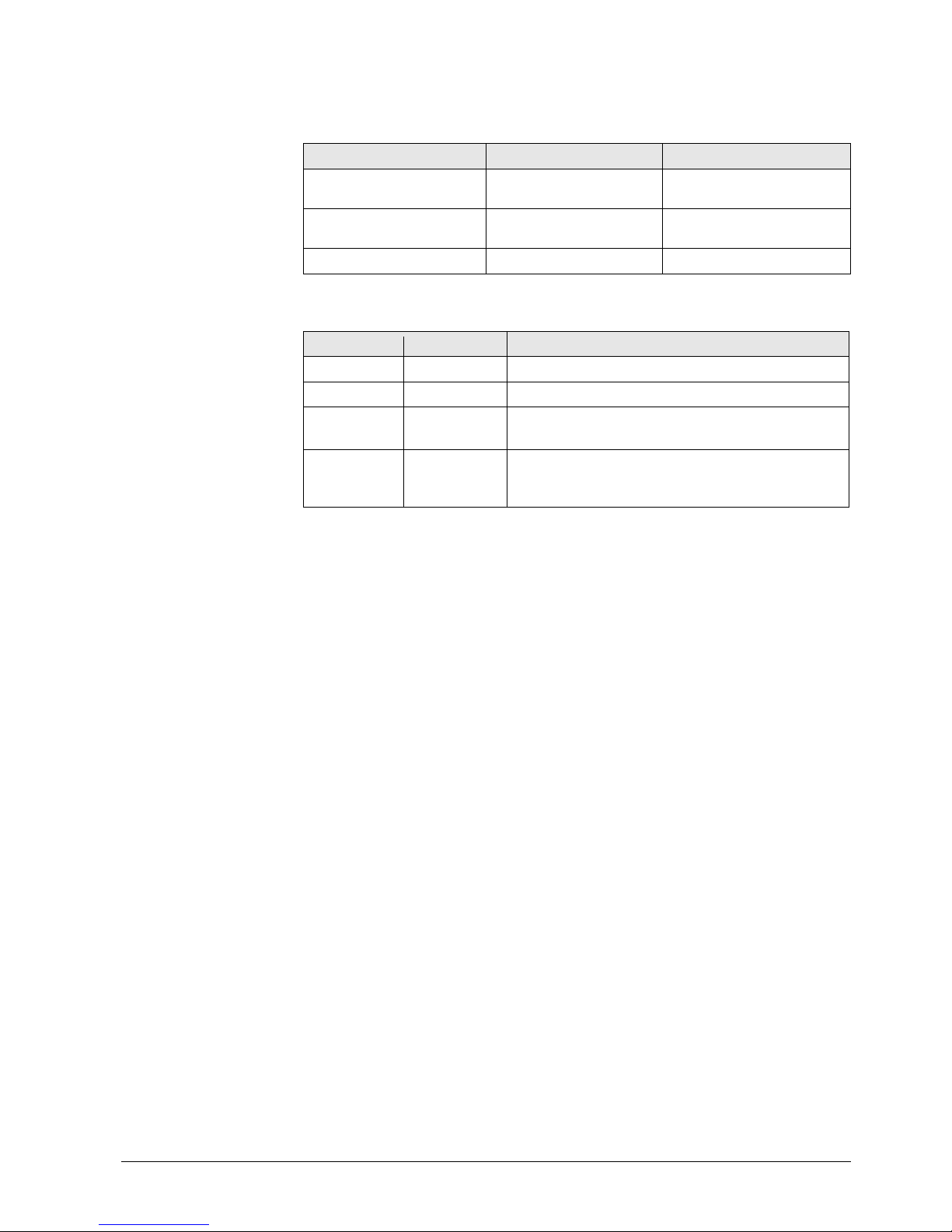
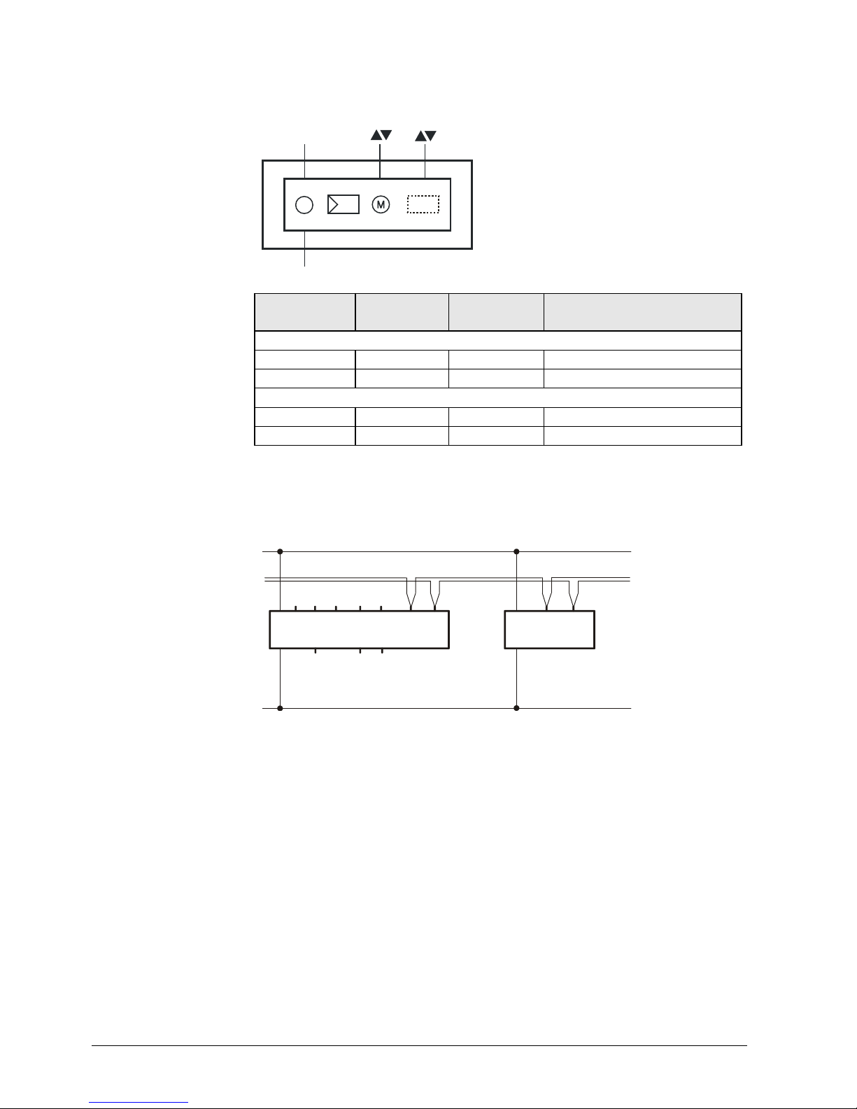
2.4 Human-machine interface
User interaction with the VAV compact controllers’ human-machine interface (HMI)
(multicolor LED and push-button) is described below, cf. also section 6.3.1.
Activity Push-but ton operation Confirmation
Enter / leave addressing
mode
Press button < 1s LED turns red or gets off
Reset to factory settings Press button > 20s LED flashes orange until
device restarts
PL-Link connection test1) Press key >2s and < 20s LED flashes 1x orange
Color
Pattern
Off --- Fault free operation or device not powered
Green steady Connection test successful
1)
Orange flashing a) Factory reset in progress
b) When a connection test was triggered: wait
1)
Red steady c) Device is in programming/addressing mode
d) When a connection test was triggered: Connection
test failed
2)
1)
Function or part of the function available in PL-Link operation only
The VAV compact controllers can be set into addressing/programming mode by
push-button:
ƒ Press push button (>0.1s and <1s)
ƒ KNX bus wiring OK ⇓ LED turns red until addressing/programming is finished
ƒ KNX bus wiring not OK ⇓ LED stays dark
The VAV compact controllers can be reset by push-button:
ƒ Press push button > 20s
ƒ LED flashes orange
ƒ Device restarts
All parameters which can be set by the OEM are reset to the OEM default values.
Push button
LED state display
Addressing and bus
test with push button
Reset with push button
14 / 44
Siemens VAV compact controller KNX/PL-Link G..B181.1E/KN CE1P3547en
Building Technologies 2017-03-23
2.5 Internal diagrams
The VAV compact controllers are supplied with two prewired connecting and
communication cables.
Χp
(G) (CE+) (CE-)
1 1 2
(G0)
2
3547G01
Tool
Tool = Configuration and maintenance interf ace
(Series E and newer: 7-pin)
Core
designation
Core color
Terminal
code
Description
Cable 1: Power / black sheathing
1 red (RD) G System voltage AC 24 V
2 black (BK) G0 System neutral AC 24 V
Cable 2: Bus / green sheathing
1 red (RD) CE+ Bus (KNX / PL-Link)
2 black (BK) CE- Bus (KNX / PL-Link)
The VAV compact controllers are connected to the bus as KNX devices according
to the KNX-TP1 standard. KNX-specific limitations regarding cable length, power
supply, number of attachable devices, and distances apply. For more details please
refer to [13] and [16] or to the KNX standard.
N1 G..B181.1E/KN
N2 RDG400KN (Example for a VAV enabled room unit)
Terminal layout may differ for each device. Devices with twin-terminals or internally
connected terminals may be encountered as well as bus connection in junction
boxes. Please refer to the technical basic documentation for product specific
information.
∂ The operating voltage at terminals G and G0 must comply with the
requirements under SELV or PELV.
∂ Safety transformers with twofold insulation as per EN 61558 required; they
must be designed to be on 100 % of the time.
G
CE+
CE-
G0
N1
3547A01
G
CE+
CE-
G0
X1M U1 D1 GND
Y10 Y1 Y2
N2
Internal diagram
(Applies to all types)
Power supply and bus
cable (color coded and
labeled)
Wiring diagram VAV
Connection to the KNX
TP1-Bus
Note
 Loading...