

Siemens OP7,OP17 Equipment Manual

RGB ELEKTRONIKA AGACIAK CIACIEK
SPÓŁKA JAWNA
Jana Dlugosza 2-6 Street
51-162 Wrocław
Poland
biuro@rgbelektronika.pl
+48 71 325 15 05
www.rgbautomatyka.pl
www.rgbelektronika.pl
DATASHEET
www.rgbautomatyka.pl
www.rgbelektronika.pl
OTHER SYMBOLS:
6AV3617-1JC20-0AX1 COVER
SIEMENS
YOUR
PARTNER IN
MAINTENANCE
At our premises in Wrocław, we have a fully equipped servicing facility. Here we perform all the repair
works and test each later sold unit. Our trained employees, equipped with a wide variety of tools and
having several testing stands at their disposal, are a guarantee of the highest quality service.
OUR SERVICES
ENCODERS
SERVO
DRIVERS
LINEAR
ENCODERS
SERVO AMPLIFIERS
CNC
MACHINES
MOTORS
POWER
SUPPLIERS
OPERATOR
PANELS
CNC
CONTROLS
INDUSTRIAL
COMPUTERS
PLC
SYSTEMS
Repair this product with RGB ELEKTRONIKA
ORDER A DIAGNOSIS
∠
Buy this product at RGB AUTOMATYKA
BUY
∠
SIMATIC HMI
Preface, Contents
1
Part I Introduction
2
3
Part II Basic Functions
OP7, OP17
Operator Panel
Equipment Manual
10
11
Part III Expanded, Configurable
Functions
13
14
Part IV Commissioning and
Description of Devices
16
A
Part V Appendix
F
Glossary, Index
6AV3991–1AE05–1AB0
Release 04/99
Safety
Guidelines
!
!
This manual contains notices which you should observe to ensure your own personal safety, as
well as to protect the product and connected equipment. These notices are highlighted in the
manual by a warning triangle and are marked as follows according to the level of danger:
Warning
indicates that death, severe personal injury or substantial property damage can result if proper
precautions are not taken.
Caution
indicates
that minor personal injury or property damage can result if proper precautions are not
taken.
Note
draws
your attention to particularly important information on the product, handling the product, or
to a particular part of the documentation.
Qualified Personnel
Correct Usage
!
Trademarks
Equipment
may be commissioned and operated only by
qualified
personnel
. Qualified personnel
within the meaning of the safety notices in this manual are persons who are authorized to commis
sion, ground and identify equipment, systems and circuits in accordance with safety engineering
standards.
Note the following:
Warning
The equipment may be used only for the applications stipulated in the catalog and in the techni-
cal description and only in conjunction with other equipment and components recommended or
approved by Siemens.
must not take place until it is established that the machine, which is to accommodate this
Startup
component, is in conformity with the guideline 89/392/EEC.
Faultless and safe operation of the product presupposes proper transportation, proper storage,
erection and installation as well as careful operation and maintenance.
SIMATIC is a registered trademark of Siemens AG.
Some of the other designations used in these documents are also registered trademarks; the
owner’s rights may be violated if they are used be third parties for their own purposes.
-
Impressum
Copyright
The reproduction, transmission or use of this document or its
contents is not permitted without express written authority.
Offenders will be liable for damages. All rights, including rights
created
reserved.
Siemens
Automation & Drives
SIMA
TIC Human Machine Interface
Postfach 4848,
Siemens Aktiengesellschaft
Siemens
by patent grant
AG,
D-90327 Nuernberg
AG 1996 All rights reserved
or registration of a utility model or design, are
Editor and Publisher: A&D PT1
Disclaimer of Liability
We
have checked the contents of this manual for agreement with
hardware
cluded
data
rections
ment
T
Order No. 6A
Equipment
and software described. Since deviations cannot be pre
entirely
in this manual
are welcomed.
echnical data subject to change.
Siemens
, we cannot guarantee full agreement. However
are reviewed regularly and any necessary cor
included in subsequent editions. Suggestions for improve
AG 1996
V3991–1AE05–1AB0
Manual OP7, OP17
the
-
, the
-
-
Preface
Guide through the
manual
The
“OP7, OP17 Operator Panel” equipment manual is divided into five
parts:
Part Chapter Contents
Conventions
1
Appendix
The following conventions are used in this manual:
Motor off Text
Variable
Screens
1 – 2
3 – 10 Step-by-step instructions on how you control the
1 – 13
14 – 16
A – F
Overview of the OPs and their range of func
tions.
OPs with the standard screens.
Expanded functions of the OPs (online changes
to system settings, PLC jobs and the scheduler).
–
Mechanical and electrical installation
– Commissioning
–
Detailed information about the OPs and their
maintenance
Contains general tables and a list of the techni
cal terms used in this manual.
on the display of the OP is shown in
“typewriter” style.
Symbolic names representing variable values on the
display are shown in italic ”typewriter” style.
Functions which you can choose are shown in
normal italics.
-
-
Equipment
Release 04/99
Manual OP7, OP17
Scr
eens →Print
ESC
Steps that are performed in succession are linked by
an arrow
The names of keys are shown in a dif
.
ferent typeface.
i
Preface
History
The
various editions of this equipment manual correspond to the following
firmware and ProT
ool versions:
Edition Remark ProT
09/96
First edition of the “OP7, OP17 Opera
tor Panel” equipment manual
04/99 T
Other support
In the case of technical queries, please contact your local Siemens in the sub
sidiaries and branches responsible for your area. Refer to Appendix F of this
equipment manual for a list of addresses.
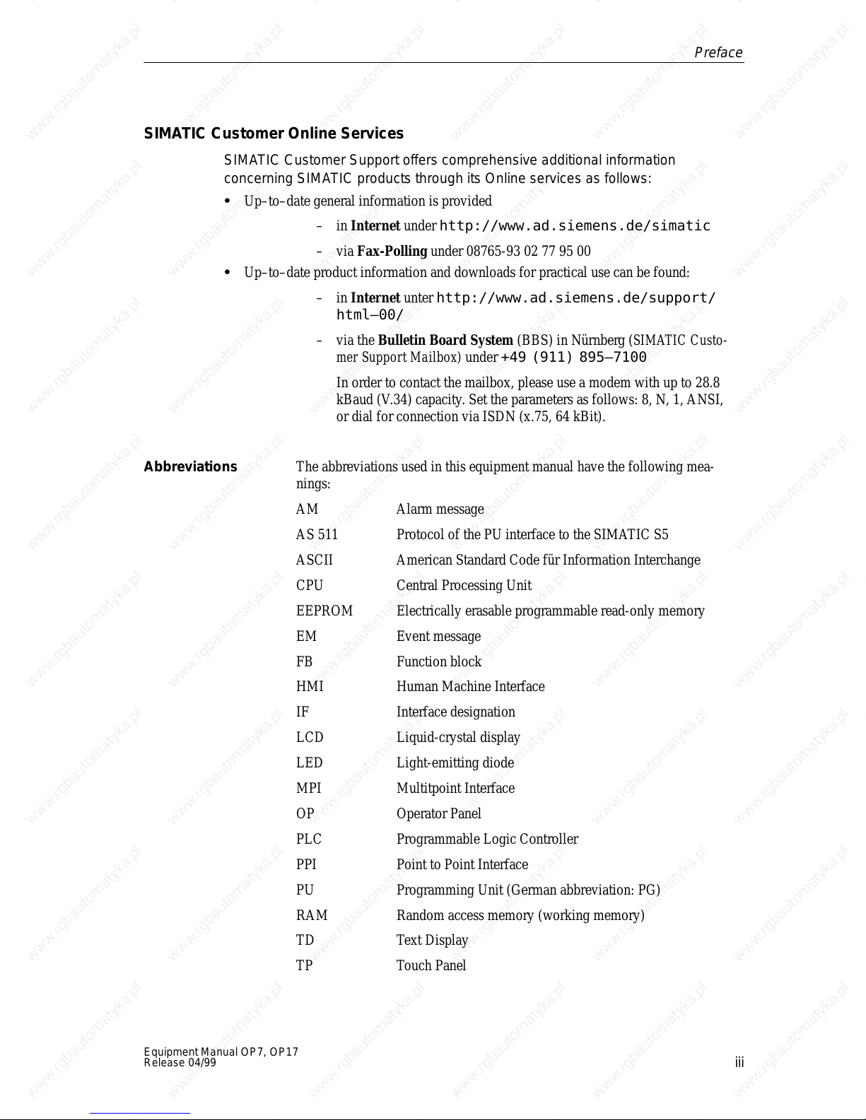
SIMATIC Customer Support Hotline
Available
worldwide, at all times:
Johnson City
echnical revision
Nuernberg
-
V 2.5 or higher
V5.01 or higher
ool V
ersion
-
Nuernberg
SIMATIC BASIC Hotline
Local
time:
Mon - Fri 8:00 to 18:00
T
elephone:
+49 (911) 895-7000
Fax:
E-Mail: simatic.support@
SIMATIC
(charged,
SIMA
T
ime:
Mon - Fri 0:00 to 24:00
T
elephone:
+49 (911) 895-7777
Fax:
+49 (911) 895-7001
+49 (911) 895-7002
nbgm.siemens.de
Premium Hotline
only with
TIC Card)
Simatic
Basic Hotline
Johnson City
SIMATIC BASIC Hotline
Local time:
Mon - Fri 8:00 to 17:00
T
elephone:
+1 423 461-2522
Fax:
E-Mail: simatic.hotline@
+1 423 461-2231
sea.siemens.com
Singapur
Singapur
SIMATIC BASIC Hotline
Local time:
Mon - Fri 8:00 to 17:30
T
elephone:
+65 740-7000
Fax:
E-Mail: simatic@
+65 740-7001
singnet.com.sg
ii
Equipment
Manual OP7, OP17
Release 04/99
SIMATIC Customer Online Services
Preface
SIMATIC
concerning SIMA
Up–to–date
Abbreviations
Customer Support of
fers comprehensive additional information
TIC products through its Online services as follows:
general information is provided
–
in
–
Internet
via
Fax-Polling
under
http://www.ad.siemens.de/simatic
under 08765-93 02 77 95 00
Up–to–date product information and downloads for practical use can be found:
–
in
Internet
unter
http://www.ad.siemens.de/support/
html–00/
–
via the
Bulletin Board System
mer Support Mailbox)
In
order to contact the mailbox, please use a modem with up to 28.8
kBaud (V
.34) capacity
under
. Set the parameters as follows: 8, N, 1, ANSI,
(BBS) in Nürnber
g (
SIMA
+49 (911) 895–7100
TIC Custo
or dial for connection via ISDN (x.75, 64 kBit).
The abbreviations used in this equipment manual have the following mea
nings:
AM
AS 51
ASCII
1
Alarm message
Protocol of the PU interface to the SIMA
TIC S5
American Standard Code für Information Interchange
-
-
CPU
EEPROM
EM
FB
HMI
IF
LCD
LED
MPI
OP
PLC
PPI
PU
RAM
TD T
TP T
Central Processing Unit
Electrically erasable programmable read-only memory
Event message
Function block
Human Machine Interface
Interface designation
Liquid-crystal display
Light-emitting diode
Multitpoint Interface
Operator Panel
Programmable Logic Controller
Point to Point Interface
Programming Unit (German abbreviation: PG)
Random access memory (working memory)
ext Display
ouch Panel
Equipment
Release 04/99
Manual OP7, OP17
iii

Preface
iv
Equipment
Manual OP7, OP17
Release 04/99
Contents
Part I Introduction
1 Product
1.1 Configuration
1.2 Visualizing
1.3 Design
1.4 Design
2 Functionality 2-1
Description
of Operator Panel OP7
of Operator Panel OP17
. . . . . . . . . . . . . . . . . . . . . . . . . . . . . . . . . . . . . . . . . . . . . . . . . . . . . . . . . . . .
. . . . . . . . . . . . . . . . . . . . . . . . . . . . . . . . . . . . . . . . . . . . . . . . . . . .
and process control phases
and controlling processes
. . . . . . . . . . . . . . . . . . . . . . . . . . . . . . . . . . . .
. . . . . . . . . . . . . . . . . . . . . . . . . . . . . . . . . . .
. . . . . . . . . . . . . . . . . . . . . . . . . .
. . . . . . . . . . . . . . . . . . . . . . . . . . . . . .
1-1.
1-1.
1-3.
1-6.
1-8.
Part II Basic Functions
3 General
3.1 Integrated
3.1.1 System
3.2 Entering Values 3-6.
3.2.1 Entering
3.2.2 Entering
3.2.3 Entering
3.2.4 Entering T
3.3 Help Text 3-14.
4 Using the OP with Its Standard Functions 4-1.
Operation
Keys
Numerical V
Alphanumeric V
Symbolic V
. . . . . . . . . . . . . . . . . . . . . . . . . . . . . . . . . . . . . . . . . . . . . . . . . . . . . .
keyboard
. . . . . . . . . . . . . . . . . . . . . . . . . . . . . . . . . . . . . . . . . . . . . . . . . . .
imer V
. . . . . . . . . . . . . . . . . . . . . . . . . . . . . . . . . . . . . . . . . . . . . . . . . . . . . .
. . . . . . . . . . . . . . . . . . . . . . . . . . . . . . . . . . . . . . . . . . . . .
. . . . . . . . . . . . . . . . . . . . . . . . . . . . . . . . . . . . . . . . . . . . . . . . .
alues 3-7.
alues 3-11.
alues 3-12.
. . . . . . . . . . . . . . . . . . . . . . . . . . . . . . . . . . . . . . .
alues 3-8.
. . . . . . . . . . . . . . . . . . . . . . . . . . . . . . . . . . . . . . . . . . .
. . . . . . . . . . . . . . . . . . . . . . . . . . . . . . . . . . . .
. . . . . . . . . . . . . . . . . . . . . . . . . . . . . . . . . . . . . . . .
. . . . . . . . . . . . . . . . . . . . . . . . . . . . . . . .
3-1.
3-1.
3-2.
4.1 Operating
4.2 Standard
4.3 Branching
5 Screens 5-1
5.1 Screen
5.2 Selecting
5.3 Editing
5.4 Printing
6 Password
6.1 Password
6.2 Logging-in
6.3 Password
Equipment Manual OP7, OP17
Release 04/99
. . . . . . . . . . . . . . . . . . . . . . . . . . . . . . . . . . . . . . . . . . . . . . . . . . . . . . . . . . . . . . . . .
Protection
Levels
Screens
in Standard Screens
Entries
Screens
Screens
Screens
Levels and Access
and logging-out on the OP (LOGIN/LOGOUT)
Management
. . . . . . . . . . . . . . . . . . . . . . . . . . . . . . . . . . . . . . . . . . . . . . . .
. . . . . . . . . . . . . . . . . . . . . . . . . . . . . . . . . . . . . . . . . . . . . . .
. . . . . . . . . . . . . . . . . . . . . . . . . . . . . . . . . . .
. . . . . . . . . . . . . . . . . . . . . . . . . . . . . . . . . . . . . . . . . . . . . . . . . .
. . . . . . . . . . . . . . . . . . . . . . . . . . . . . . . . . . . . . . . . . . . . . . .
. . . . . . . . . . . . . . . . . . . . . . . . . . . . . . . . . . . . . . . . . . . . . . . . .
. . . . . . . . . . . . . . . . . . . . . . . . . . . . . . . . . . . . . . . . . . . . . . . .
. . . . . . . . . . . . . . . . . . . . . . . . . . . . . . . . . . . . . . . . . . . . . . . . . . .
. . . . . . . . . . . . . . . . . . . . . . . . . . . . . . . . . . . . .
. . . . . . . . . . . . . . . . . . . . . . . . . . . . . . . . . . . . . . . . . .
. . . . . . . . . . . .
4-1.
4-3.
4-5.
5-2.
5-3.
5-4.
5-4.
6-1.
6-1.
6-3.
6-4.
v
7 Messages 7-1
. . . . . . . . . . . . . . . . . . . . . . . . . . . . . . . . . . . . . . . . . . . . . . . . . . . . . . . . . . . . . . .
7.1 Message
7.1.1 Event
7.1.2 Alarm
7.1.3 System
7.2 Displaying
7.2.1 Display
7.2.2 Scrolling
7.2.3 Viewing
7.3 Message
7.4 Deleting
7.4.1 Deleting
7.4.2
Deleting alarm and event messages via standard screens
7.4.3 Automatically
7.5
Printing Messages
7.5.1 Direct
7.5.2 Printing
8 Recipes 8-1
. . . . . . . . . . . . . . . . . . . . . . . . . . . . . . . . . . . . . . . . . . . . . . . . . . . . . . . . . . . . . . . . .
8.1 Creating
8.2 Copying
8.3 Transferring
types
and alarm messages
messages
messages
Messages
Sequences
through W
Event and Alarm Message T
Buf
Messages
. . . . . . . . . . . . . . . . . . . . . . . . . . . . . . . . . . . . . . . . . . . . . . . . .
. . . . . . . . . . . . . . . . . . . . . . . . . . . . . . . . . . . . . . .
. . . . . . . . . . . . . . . . . . . . . . . . . . . . . . . . . . . . . . . . . . . . . . . .
. . . . . . . . . . . . . . . . . . . . . . . . . . . . . . . . . . . . . . . . . . . . . .
. . . . . . . . . . . . . . . . . . . . . . . . . . . . . . . . . . . . . . . . . . . .
. . . . . . . . . . . . . . . . . . . . . . . . . . . . . . . . . . . . . . . . . . . . . .
aiting Messages at Message Level
ext 7-9.
. . . . . . . . . . . . . . . . . . . . . . . . . . . .
fers 7-10.
. . . . . . . . . . . . . . . . . . . . . . . . . . . . . . . . . . . . . . . . . . . . . . . .
. . . . . . . . . . . . . . . . . . . . . . . . . . . . . . . . . . . . . . . . . . . . . .
alarm message and event message buf
Deleting the System Message Buf
. . . . . . . . . . . . . . . . . . . . . . . . . . . . . . . . . . . . . . . . . . . . . .
Message Logging
the Message Buf
and Editing Data Records
Data Records
Data Records
. . . . . . . . . . . . . . . . . . . . . . . . . . . . . . . . . . . . . . . . .
fer 7-15.
. . . . . . . . . . . . . . . . . . . . . . . . . . . . . . . . . . . . . .
. . . . . . . . . . . . . . . . . . . . . . . . . . . . . . . .
. . . . . . . . . . . . . . . . . . . . . . . . . . . . . . . . . . . . . . . . . . .
. . . . . . . . . . . . . . . . . . . . . . . . . . . . . . . . . . . . . . .
. . . . . . . . . . . . . . .
fers upon buffer overflow
. . . . . . . . . . . .
fer upon Buf
fer Overflow
7-2.
7-2.
7-4.
7-6.
7-7.
7-8.
7-8.
7-12.
7-12
7-13.
7-13
7-14.
7-14.
8-4.
8-6.
8-7.
8.4 Deleting
Data Records
9 STATUS/FORCE VAR with the OP
9.1 FORCE VAR 9-2.
10 System Settings 10-1.
10.1 Selecting
10.2 Modifying
10.3 Adjusting
10.4 Setting
OP Modes
. . . . . . . . . . . . . . . . . . . . . . . . . . . . . . . . . . . . . . . . . . . . . . . . . . .
. . . . . . . . . . . . . . . . . . . . . . . . . . . . . . . . . . . . . . . . . . . . . . . . . . . . . . . .
a Language
Parameters in Online Mode
Contrast
. . . . . . . . . . . . . . . . . . . . . . . . . . . . . . . . . . . . . . . . . . . . . .
. . . . . . . . . . . . . . . . . . . . . . . . . . . . . . . . . . . . . . . . . . . . . . .
. . . . . . . . . . . . . . . . . . . . . . . . . . . . . . . . . . . . . . . . . . .
. . . . . . . . . . . . . . . . . . . . . . . . . . . . . . . . . . . . . . . .
. . . . . . . . . . . . . . . . . . . . . . . . . . . . . . . . . . . . . . . . . . .
. . . . . . . . . . . . . . . . . . . . . . . . . . . . .
8-10.
9-1.
10-1.
10-2.
10-4.
10-5.
vi
Equipment Manual OP7, OP17
Release 04/99
Part III Expanded, Configurable Functions
11 Process-Dependent
11.1 Branching
11.2 Self-Defined
12 Schedulers
13 Controlling
(OP17 only)
the OP from the PLC
Operator Guidance
. . . . . . . . . . . . . . . . . . . . . . . . . . . . . . . . . .
by Means of Soft Keys and Function Keys
Screen Hierarchy
. . . . . . . . . . . . . . . . . . . . . . . . . . . . . . . . . . . .
. . . . . . . . . . . . . . . . . . . . . . . . . . . . . . . . . . . . . . . . . . . . . . . . .
. . . . . . . . . . . . . . . . . . . . . . . . . . . . . . . . . . . . . . . .
. . . . . . . . . . . . . . . .
11-1.
11-1.
11-3.
12-1.
13-1.
Part IV Commissioning and Description of Devices
14 Installation 14-1.
14.1 Mechanical
14.2 Electrical
14.2.1 Connecting
14.2.2 Connecting
14.2.3 Connections
14.2.4 Loop-Through
14.2.5 Connecting
15 Commissioning 15-1
15.1 Initial
15.2 Recommissioning 15-4
. . . . . . . . . . . . . . . . . . . . . . . . . . . . . . . . . . . . . . . . . . . . . . . . . . . . . . . . . . . . .
Installation
Installation
. . . . . . . . . . . . . . . . . . . . . . . . . . . . . . . . . . . . . . . . . . .
. . . . . . . . . . . . . . . . . . . . . . . . . . . . . . . . . . . . . . . . . . . . .
the Power Supply
a Configuration Computer
to PLC
. . . . . . . . . . . . . . . . . . . . . . . . . . . . . . . . . . . . . . . . . . . . .
Mode (OP17 only)
a Printer
. . . . . . . . . . . . . . . . . . . . . . . . . . . . . . . . . . . . . . . . . . . . .
. . . . . . . . . . . . . . . . . . . . . . . . . . . . . . . . . . . .
. . . . . . . . . . . . . . . . . . . . . . . . . . . . .
. . . . . . . . . . . . . . . . . . . . . . . . . . . . . . . . .
14-2.
14-3.
14-4.
14-5.
14-6.
14-8.
14-9.
. . . . . . . . . . . . . . . . . . . . . . . . . . . . . . . . . . . . . . . . . . . . . . . . . . . . . . . . .
commissioning
. . . . . . . . . . . . . . . . . . . . . . . . . . . . . . . . . . . . . . . . . . . .
15-3.
. . . . . . . . . . . . . . . . . . . . . . . . . . . . . . . . . . . . . . . . . . . . . . . .
15.3 Start-up
15.4 Testing
15.5 Testing
15.6 Testing
16 Device
Description
16.1 OP7 16-1
16.2 OP17 16-3
16.3 Labeling
16.4 Optional
16.5 Maintenance 16-9
Behavior
the Configuration in OFFLINE Mode
the Configuration in Conjunction with the PLC
Communication via the PROFIBUS-DP
. . . . . . . . . . . . . . . . . . . . . . . . . . . . . . . . . . . . . . . . . . . . . . .
. . . . . . . . . . . . . . . . . . . . . . . .
. . . . . . . . . . . . . . .
. . . . . . . . . . . . . . . . . . . . .
. . . . . . . . . . . . . . . . . . . . . . . . . . . . . . . . . . . . . . . . . . . . . . . . . . . . .
. . . . . . . . . . . . . . . . . . . . . . . . . . . . . . . . . . . . . . . . . . . . . . . . . . . . . . . . . . . .
. . . . . . . . . . . . . . . . . . . . . . . . . . . . . . . . . . . . . . . . . . . . . . . . . . . . . . . . . . .
of the Function Keys
Backup Battery for the OP17
. . . . . . . . . . . . . . . . . . . . . . . . . . . . . . . . . . . .
. . . . . . . . . . . . . . . . . . . . . . . . . . . . .
. . . . . . . . . . . . . . . . . . . . . . . . . . . . . . . . . . . . . . . . . . . . . . . . . . . .
15-5.
15-6.
15-7.
15-8.
16-1.
16-5.
16-8.
Equipment Manual OP7, OP17
Release 04/99
vii

Part V Appendix
A Brief
B System
C Technical
D Interface
E SIMATIC
Description of Standard Screens
Messages
Data
. . . . . . . . . . . . . . . . . . . . . . . . . . . . . . . . . . . . . . . . . . . . . . . . . . . . . .
. . . . . . . . . . . . . . . . . . . . . . . . . . . . . . . . . . . . . . . . . . . . . . . . . . . . . . . . .
Assignment
HMI Documentation
F Siemens Worldwide F-1.
. . . . . . . . . . . . . . . . . . . . . . . . . . . . . . . . . . .
A-1.
B-1.
C-1.
. . . . . . . . . . . . . . . . . . . . . . . . . . . . . . . . . . . . . . . . . . . . . . . . . . .
. . . . . . . . . . . . . . . . . . . . . . . . . . . . . . . . . . . . . . . . . . . .
D-1.
E-1.
. . . . . . . . . . . . . . . . . . . . . . . . . . . . . . . . . . . . . . . . . . . . . . . . . . . .
viii
Equipment Manual OP7, OP17
Release 04/99

Part
I
Introduction
Product Description
Functionality
1
2

2-2
Equipment
Manual OP7, OP17
Release 04/99

Product Description
1
Applications of
OP7 and OP17
Operator
and malfunctions of a connected PLC to be visualized. In addition, inputs can
be made on the OP which can be written directly to the PLC. Some functions
relating to machine diagnostics can also be executed on the Operator Panel.
The Operator Panels feature a number of standard functions. The displays
and operation of the devices can be optimized by the configurer to meet the
requirements of the process.
The Operator Panels are suitable for fitting into switching cabinets and con
trol desks. A printer can be attached to the OP for logging processes during
automation operation.
1.1 Configuration
Creating data
areas
Before
visualizing data from the PLC, i.e. it has to be configured. As far as the PLC
is concerned, data areas used by the OP to communicate with the PLC have
to be created in the memory
Panels OP7 and OP17 allow operating states, current process values
-
and process control phases
an OP can go into service, it has to be prepared for its job of
.
Configuration with
ProTool
Equipment Manual OP7, OP17
Release 04/99
The configuration for the OP is created on a computer (PC/PU) using
ProT
ool configuration software under Microsoft W
configuration is ready, it is transferred to the OP
however
transfer of the configuration, the OP has to be connected to the PLC.
The OP now communicates with the PLC and reacts to program flows on the
PLC on the basis of the configured requirements.
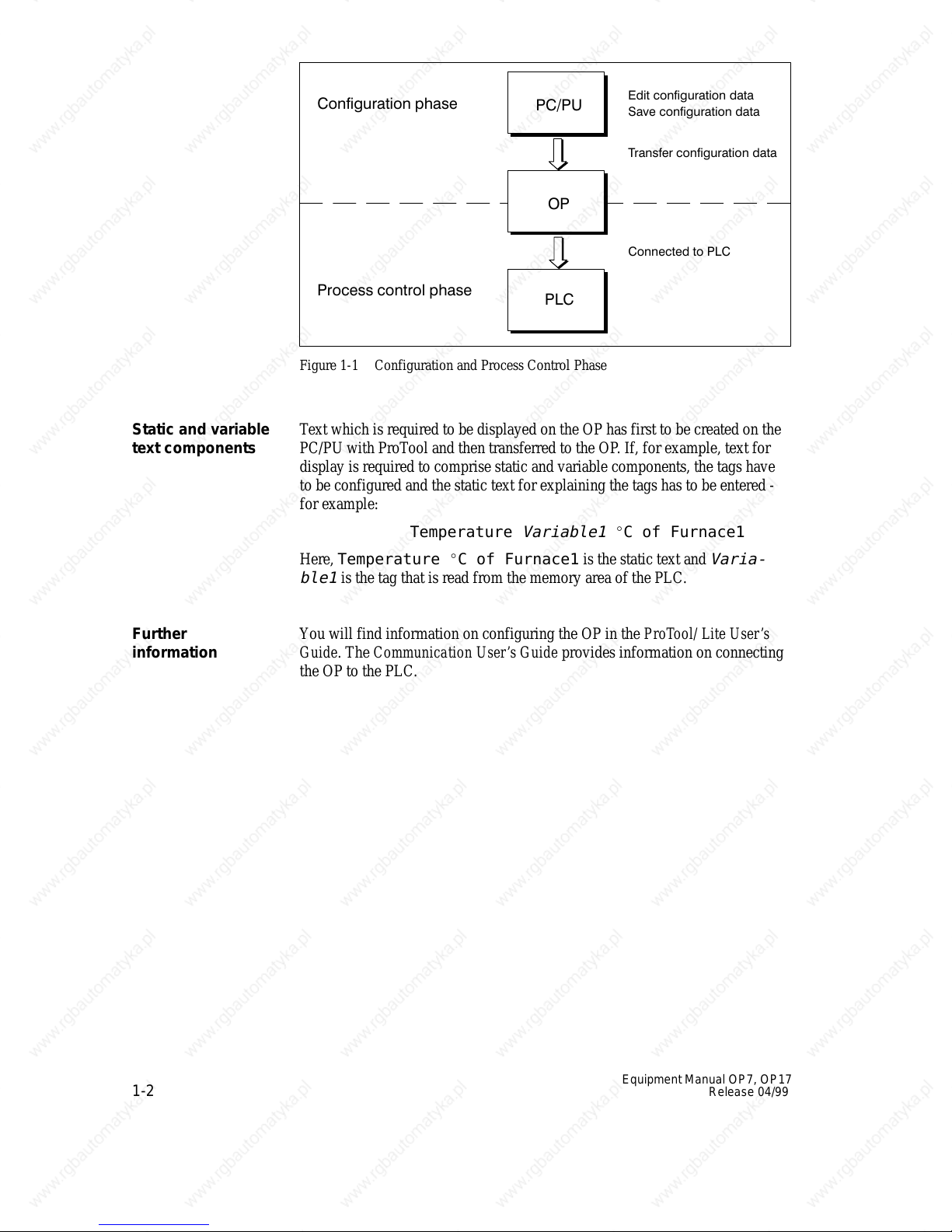
figure 1-1 depicts the configuration and process control phases described
above:
, the computer has to be connected to the Operator Panel. Following
indowsTM. When the
. Before this can be done,
1-1
Static
and variable
text components
Further
information
Figure 1-1 Configuration and Process Control Phase
Text
which is required to be displayed on the OP has first to be created on the
PC/PU with ProT
ool and then transferred to the OP
. If, for example, text for
display is required to comprise static and variable components, the tags have
to be configured and the static text for explaining the tags has to be entered -
for example:
Temperature
Here,
Temperature C of Furnace1
ble1
is the tag that is read from the memory area of the PLC.
Y
ou will find information on configuring the OP in the
Guide
. The
Communication User’s Guide
Variable1
C of Furnace1
is the static text and
ProT
ool/ Lite User
provides information on connecting
Varia-
’s
the OP to the PLC.
1-2
Equipment
Manual OP7, OP17
Release 04/99
1.2 Visualizing and controlling processes
The
Display and
control functions
basic functions of an OP consist in displaying process states and in con
trolling the process. The following display and control functions can be con
figured on Operator Panels OP7 and OP17:
screens
event messages
alarm messages
recipes
help text
logging
languages
schedulers for the OP17
-
-
Screens
Event messages
Data supplied by the PLC may be displayed together on a screen and modi
fied individually
since, for example, more related data are required for describing a machine
state than can normally be displayed in the window of a screen. Therefore
data on operating temperature, fill level, speed and running time can illus
trate the current machine state.
The OP7 and OP17 are Operator Panels with text based displays. Accordin
gly
, a screen on the display comprises text items which may include static
text and current state values.
Screens may be combined on the OP in a directory
to display
Event messages are information and operating notes on current machine and
process states during regular production operations. Event messages may
contain process values. Process values are displayed either numerically - for
example,
Motor running at 3000 revs
or
symbolically - for example,
Motor running normally,
where
a specific control value is assigned to
, if required. A screen consists of several screen entries
. Y
ou can use the directory
, print and edit screens.
normally.
-
-
-
The classification of a message as an event message is done at the configura
tion stage.
Equipment
Release 04/99
Manual OP7, OP17
-
1-3

Alarm
messages
Alarm
messages show
dur ing production operations. Due to their ur
, in contrast to event messages, critical machine states
gency
, they have to be acknowl
edged before any other action is possible.
Alarm messages may contain process values. Process values are displayed
either numerically - for example
Motor speed 4500
or
symbolically - for example
Motor speed too high,
where
a specific control value is assigned to
This
type of message has a higher display priority than an event message. If
too high.
an alarm message is issued, any event message or screen that is being dis
played is replaced with a flashing alarm on the display
.
-
-
Recipes
Help text
The classification of a message as an alarm message is made at the configu
-
ration stage.
When a product is made up of various ingredients in certain ratios, this infor
mation is stored in a so-called recipe.
T
ake orange juice for example. Its production and bottling requires that
orange concentrate and water be mixed in a certain ratio. These values are
stored as tags in a recipe.
Each recipe can be made up of several data records containing dif
ferent va
-
lues for the recipe.
The data can be edited in the OP
, transferred to the PLC and read out from
the PLC.
In the OP
, the recipes are combined by recipe number and title in a recipe
directory.
Help text consists of configurable additional information and operator in
structions relating to event messages, alarm messages and screens. If for ex
-
-
ample an alarm message arises, this enables additional information on how to
eliminate faults to be displayed.
Help text can also be displayed by pressing a key
HELP
LED is on.
, if required, when the
-
Logging
Messages can be printed in online mode by means of the printer connected to
the OP
messages that have accumulated in the buf
1-4
. Furthermore, there is a possibility of printing all the event and alarm
fer concerned.
Equipment
Manual OP7, OP17
Release 04/99
Multilinguality
Message
several languages. Up to three of the languages listed below can be loaded
simultaneously on the same OP and presented to the operator for selection on
line:
text, screens, help text and system messages may be displayed in
German
English
French
Italian
Spanish
Russian (Cyrillic characters).
Schedulers
A scheduler is a regularly recurring point in time (i.e., hourly
annually) at which a certain function is to be executed. When a scheduler
time is reached, the configured bit is set in the interface area of the PLC and
the configured function is executed.
The following functions are available:
Print alarm message buf
Print event message buf
Select screen
Print screen
Print data record
fer
fer
, daily
, weekly
,
Equipment
Release 04/99
Manual OP7, OP17
1-5
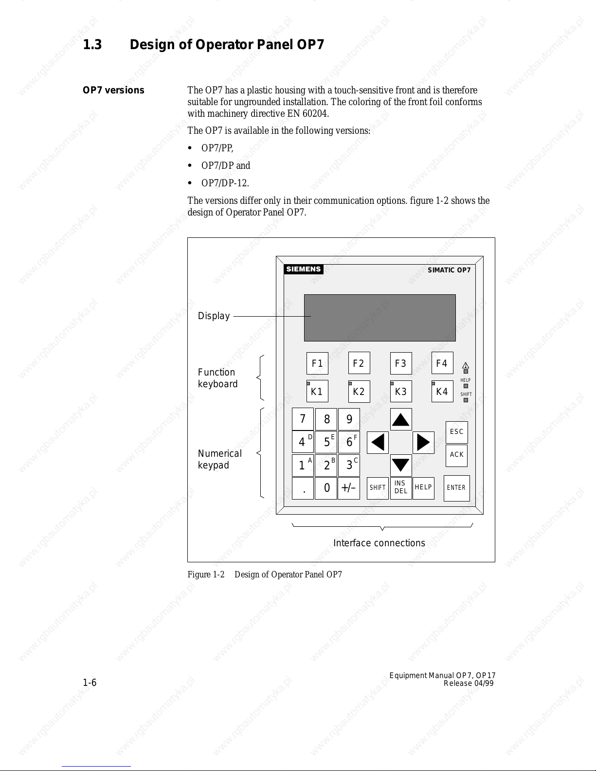
1.3 Design of Operator Panel OP7
The
OP7
versions
OP7 has a plastic housing with a touch-sensitive front and is therefore
suitable for ungrounded installation. The coloring of the front foil conforms
with machinery directive EN 60204.
The OP7 is available in the following versions:
OP7/PP,
OP7/DP and
OP7/DP-12.
The versions dif
fer only in their communication options. figure 1-2 shows the
design of Operator Panel OP7.
Display
Function
keyboard
456
Numerical
keypad
1
F1
F2 F3 F4
K1 K2 K3 K4
7
D
A
.
9
8
E
BC
3
2
+/–
0
F
SHIFT
INS
DEL
HELP
SIMA
TIC OP7
HELP
SHIFT
ESC
ACK
ENTER
Figure 1-2 Design of Operator Panel OP7
1-6
Interface
connections
Equipment
Manual OP7, OP17
Release 04/99
LCD
High-contrast
LC display with LED back-lighting. Display of up to 4 lines
each having a maximum length of 20 characters; the height of the characters
is 8 mm.
Function
keyboard
Soft keys
System keyboard
Data buffer
Interfaces
Fuse
Compatibility
8 keys (F1 to F4 and K1 to K4) for calling freely programmable, generally
valid standard functions. The green LEDs embedded in keys K1 to K4 can be
driven by the PLC.
All eight function keys may alternatively be configured as soft keys. Each of
these keys can be configured with dif
ferent functions for the various screens.
22 keys for calling universally valid, standard functions (keypad, arrow keys,
etc.).
The OP7 operates without a battery and is therefore maintenance-free. Oper
ating data are retained in a non-volatile state in the flash memory on the OP
1 x RS232/TTY for connecting to the PLC/computer/printer
1 x RS422/485 for connecting to the PLC/computer
.
Maintenance-free electronic fuse.
The OP7 is upwards compatible with the OP5. All cabling can be continue to
be used. Existing OP5 configurations can be converted automatically for the
OP7 by means of the ProTool configuration software.
-
Equipment
Release 04/99
Manual OP7, OP17
1-7
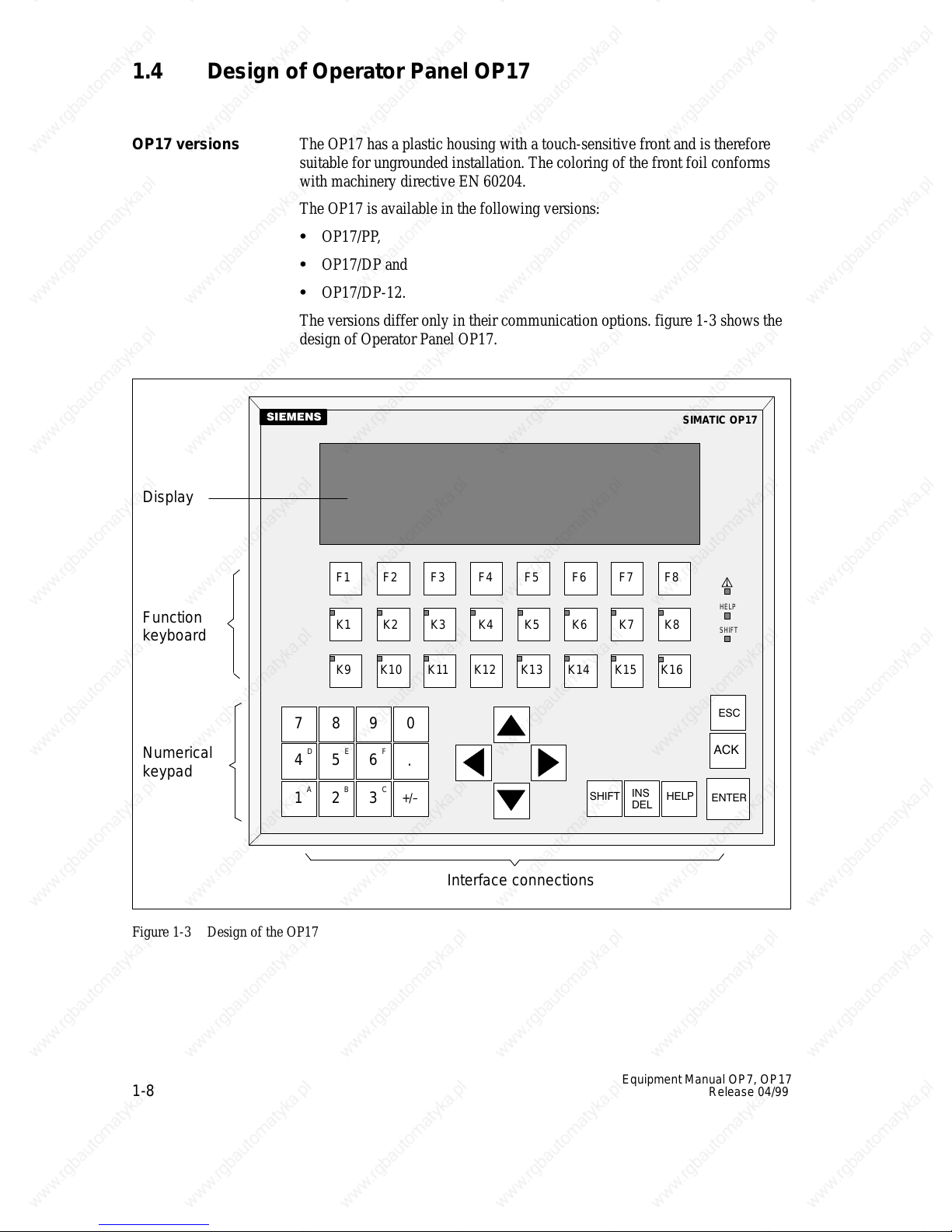
1.4 Design of Operator Panel OP17
The
OP17
versions
OP17 has a plastic housing with a touch-sensitive front and is therefore
suitable for ungrounded installation. The coloring of the front foil conforms
with machinery directive EN 60204.
The OP17 is available in the following versions:
OP17/PP,
OP17/DP and
OP17/DP-12.
Display
Function
keyboard
Numerical
keypad
The versions dif
fer only in their communication options. figure 1-3 shows the
design of Operator Panel OP17.
F1 F2 F3 F4 F5 F6 F7 F8
K1 K2 K3 K4 K5 K6 K7 K8
K9 K10 K11 K12 K13 K14 K15 K16
7 0
8
9
D
E
4
5
A
2
1
F
6
.
B
C
+/–
3
SIMA
TIC OP17
HELP
SHIFT
Figure 1-3 Design of the OP17
1-8
Interface
connections
Equipment
Manual OP7, OP17
Release 04/99
LCD
High-contrast
LC display with LED back-lighting. The following displays
can be configured:
4 lines each of 20 characters; height of characters is 1
8 lines each of 40 characters; height of characters is 6 mm.
1 mm
Function
keyboard
Softkeys
System keyboard
Data buffer
Interfaces
24 keys (F1 to F8 and K1 to K16) for calling freely configurable functions.
The two-color LEDs (red/green) embedded in keys K1 to K16 can be driven
by the PLC.
16 function keys (F1 to F8 and K1 to K8) can be used as function keys too.
Soft keys can be configured with functions which vary from screen to screen.
22 keys for calling universally valid, standard functions (keypad, arrow keys,
etc.).
The OP7 operates without a battery and is therefore maintenance-free. Oper
ating data are retained in a non-volatile state in the flash memory on the OP
The message buf
turned of
f.
fer is backed up for several hours after the power supply is
.
The internal hardware clock has reserve power for several days after the
power supply is turned of
f.
The OP17 can be optionally upgraded with a lithium battery. The battery is
not supplied with OP as a standard component.
1 x RS232/TTY active, for connecting to the PLC/computer/printer
1 x RS232/TTY passive, for connecting to the PLC/computer/printer
-
Fuse
Compatibility
Equipment
Release 04/99
Manual OP7, OP17
1 x RS422/485 for connecting to the PLC/computer
Maintenance-free electronic fuse.
The OP17 is upwards compatible with the OP15/C. All cabling can be con
tinue to be used. Existing OP15/C configurations can be converted automati
cally for the OP17 by means of the ProTool configuration software.
-
-
1-9

1-10
Equipment
Manual OP7, OP17
Release 04/99
Functionality
g
g
gq
gp
table
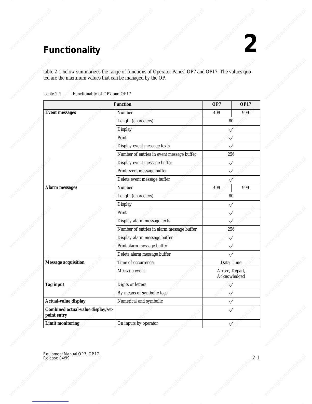
2-1 below summarizes the range of functions of Operator Panesl OP7 and OP17. The values quo
ted are the maximum values that can be managed by the OP
Table 2-1 Functionality of OP7 and OP17
Function OP7 OP17
Event messages
Alarm messages
Message acquisition
Tag input
Actual-value display Numerical and symbolic
Combined
point entry
Limit monitoring On inputs by operator
actual-value display/set
Number 499 999
Length (characters) 80
Display
Print
Display event message texts
Number of entries in event message buffer 256
Display event message buffer
Print event message buffer
Delete event message buffer
Number 499 999
Length (characters) 80
Display
Print
Display alarm message texts
Number of entries in alarm message buffer 256
Display alarm message buffer
Print alarm message buffer
Delete alarm message buffer
Time of occurrence Date, Time
Message event Arrive, Depart,
Digits or letters
By means of symbolic tags
-
.
Acknowledged
2
-
Equipment
Release 04/99
Manual OP7, OP17
2-1

Table 2-1 Functionality of OP7 and OP17, continued
p
p
y
OP17OP7Function
Password protection
Number of passwords 50
Password levels 9 (1..9)
Screens
Number 99
Display
Print
Screen entries per screen 99
Number of fields per screen 300
Number of fields per screen entry 32
Recipes
Number 99
Display
Print
Recipe entries per recipe 99
Recipe memory size (kbytes) 4 20
Data records per recipe 99
Store/retrieve data record in/from OP
Help text Length (characters) 320
Schedule times – 48
Function keys
Number 8 24
Of which can be configured as soft keys 8 16
Integrated LEDs 4 16
Reports
Diagnostics function STATUS/FORCE VAR
Loop-through operation for con-
figuration computer
Configurable OP languages German, English,
French, Italian,
Spanish, Russian
(Cyrillic characters)
Online language change Number of languages 3
2-2
Equipment
Manual OP7, OP17
Release 04/99
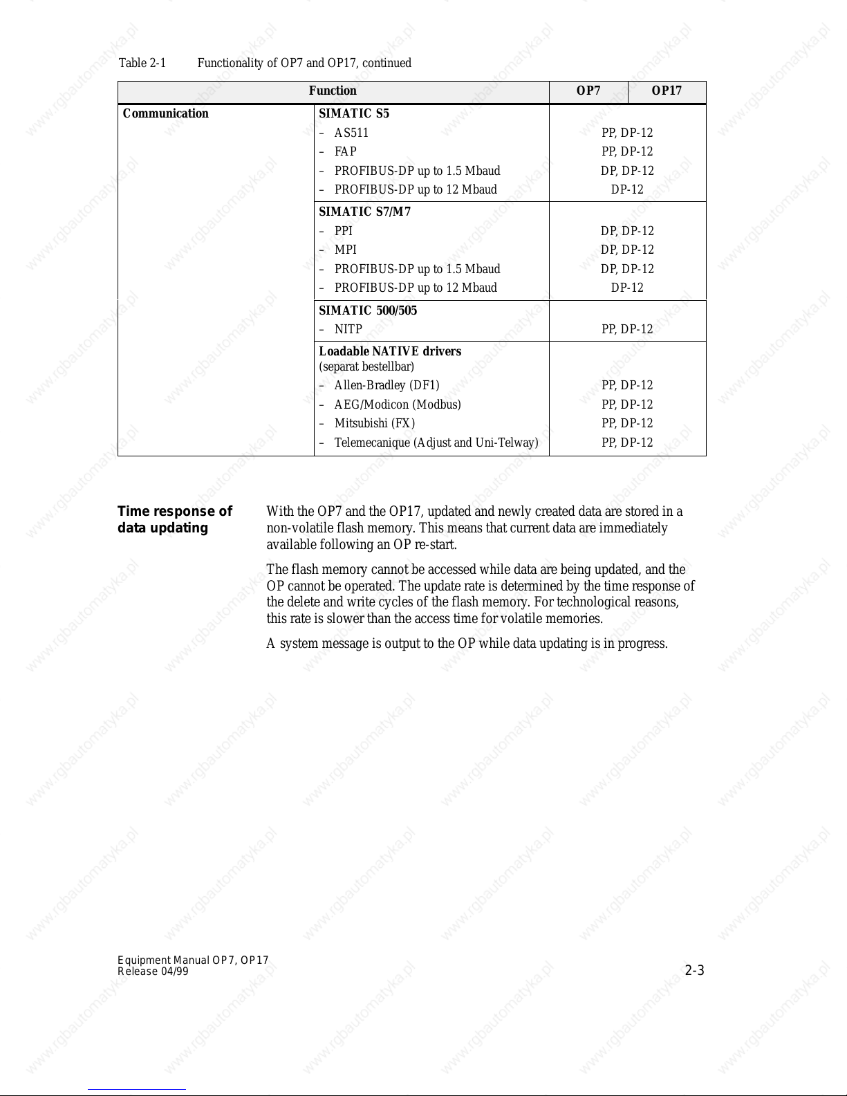
Table 2-1 Functionality of OP7 and OP17, continued
Communication
SIMATIC S5
– AS511
–FAP
– PROFIBUS-DP up to 1.5 Mbaud
– PROFIBUS-DP up to 12 Mbaud
SIMATIC S7/M7
– PPI
– MPI
– PROFIBUS-DP up to 1.5 Mbaud
– PROFIBUS-DP up to 12 Mbaud
SIMATIC 500/505
– NITP
Loadable NATIVE drivers
(separat bestellbar)
– Allen-Bradley (DF1)
– AEG/Modicon (Modbus)
– Mitsubishi (FX)
– Telemecanique (Adjust and Uni-Telway)
OP17OP7Function
PP, DP-12
PP, DP-12
DP, DP-12
DP-12
DP, DP-12
DP, DP-12
DP, DP-12
DP-12
PP, DP-12
PP, DP-12
PP, DP-12
PP, DP-12
PP, DP-12
Time response of
data updating
With
the OP7 and the OP17, updated and newly created data are stored in a
non-volatile flash memory
. This means that current data are immediately
available following an OP re-start.
The flash memory cannot be accessed while data are being updated, and the
OP cannot be operated. The update rate is determined by the time response of
the delete and write cycles of the flash memory
. For technological reasons,
this rate is slower than the access time for volatile memories.
A system message is output to the OP while data updating is in progress.
Equipment Manual OP7, OP17
Release 04/99
2-3

2-4
Equipment
Manual OP7, OP17
Release 04/99
Part
II
Basic Functions
General Operation
Using the OP with Its
Standard Functions
3
4
Screens
Password Protection
Messages
Recipes
STATUS/FORCE VAR
with the OP
System Settings
5
6
7
8
9
10

2-6
Equipment
Manual OP7, OP17
Release 04/99
 Loading...