

Page 1

Preface, Table of Contents
Introduction
COROS
Operator Panel
OP25, OP35, OP45
Equipment Manual
Functions od the Operator Panel
Commissioning and Operation
Device Description,
Installation and Maintenance
Appendices
Glossary, Index
6AV3991–1AD02–0AB0
Release 04/96
Page 2

Safety Guidelines
!
!
This manual contains notices which you should observe to ensure your own personal safety, as
well as to protect the product and connected equipment. These notices are highlighted in the
manual by a warning triangle and are marked as follows according to the level of danger:
Danger
indicates that death, severe personal injury or substantial property damage can result if proper
precautions are not taken.
Caution
indicates that minor personal injury or property damage can result if proper precautions are not taken.
Note
draws your attention to particularly important information on the product, handling the product, or
to a particular part of the documentation.
Qualified Personnel
Correct Usage
!
Trademarks
Impressum
Equipment may be commissioned and operated only by qualified personnel. Qualified personnel
within the meaning of the safety notices in this manual are persons who are authorized to commission, ground and identify equipment, systems and circuits in accordance with safety engineering
standards.
Note the following:
Warning
The equipment may be used only for the applications stipulated in the catalog and in the technical description and only in conjunction with other equipment and components recommended or
approved by Siemens.
Faultless and safe operation of the product presupposes proper transportation, proper storage,
erection and installation as well as careful operation and maintenance.
Startup must not take place until it is established that the machine, which is to accommodate this
component, is in conformity with the guideline 89/392/EEC.
SIMATIC and SINEC are registered trademarks of SIEMENS AG. Some of the other designations used in these documents are also registered trademarks; the owner’s rights may be violated
if they are used be third parties for their own purposes.
Published by AUT 91
Copyright Siemens AG 1996 All rights reserved
The reproduction, transmission or use of this document or its
contents is not permitted without express written authority.
Offenders will be liable for damages. All rights, including rights
created by patent grant or registration of a utility model or design,
are reserved.
Siemens AG
Automation Group
Industrial Automation Systems
P.O. Box 4848, D-90327 Nürnberg
Siemens Aktiengesellschaft Order No. 6AV3991–1AD02–0AB0
Equipment Manuel OP25, OP35, OP45
We have checked the contents of this manual for agreement with
the hardware and software described. Since deviations cannot be
precluded entirely , we cannot guarantee full agreement. However ,
the data in this manual are reviewed regularly and any necessary
corrections included in subsequent editions. Suggestions for
improvement are welcomed.
Technical data subject to change.
Siemens AG 1995, 1996
Page 3

Preface
Purpose
Audience
Applicability
This equipment manual contains precise information about the functionality
and technical design of operator panels OP25, OP35, and OP45.
The present equipment manual is written for operators, fitters, configurers, and
system support engineers.
The operator of an operator panel will find all the information he requires for
handling the device in Part II.
For the fitter, Part IV contains all the information he requires to install and
commission the operator panel.
The different versions of the equipment manual refer to the following OP firmware and ProT ool versions:
Release Remarks OP Firmware ProTool
Version
04/95 Initial release of Equipment
Manual
Summary of OP25, OP35 Equip-
ment Manual, and OP45 added
10/95 Extensions for Release 2 OP25: from V. 1.31
04/96 SINEC L2-DP for OP45 and MPI
for SIMATIC S7 added
1)
As well as an upgrade floppy disk
OP25: from V. 1.31
OP35: from V. 1.31
OP45: from V. 1.31
OP35: from V. 1.31
OP45: from V. 1.31
OP25: from V. 2.0
OP35: from V. 2.0
OP45: from V. 1.40
Up to V. 1.31
Up to V. 1.31
Up to V. 1.31
Up to V 2.0
Up to V 2.0
Up to V. 2.0
Up to V 2.0
Up to V 2.0
V. 2.0
1
Further support
Should you have any queries regarding technical matters, please get into touch
with your point of contact at the Siemens agency or branch responsible. You
will find the addresses in Appendix F of this manual, in catalogs, and in Compuserve (go autforum) ..., for instance. In addition, you can call our hotline by
dialing +49(911) 895-7000 (fax 7001).
Conventions
The following conventions are used in this manual:
Trans Mode T ext on the display of the OP appears in the manual in
Login: Field name on screens
( section 7.2) Cross-reference, reference to additional information
Equipment Manuel OP25, OP35, OP45
Release 04/96
Courier
i
Page 4

Preface
How the manual is
organized
The OP25/35/45 Equipment Manual is organized as follows:
Chapters 1 to 2 provide an overview of the operator panels and their
functions in tabular form.
Chapters 3 to 9 describe in step-by-step instructions how to operate oper-
ator panels – for example, how to
– create new screens (in addition to the standard
screens)
– output messages or alarms
– enter recipe data records
– print messages or screens.
Chapters 10 to 13 contain information on
– how you commission operator panels
– which system settings you can perform, and
– how you can back up and restore data.
Chapters 14 to 18 contain detailed information about the different devices,
as well as their mechanical and electrical installation and
maintenance.
In the appendices you will such items as technical data, interface assign-
ments, test functions, and system messages.
Related
documents
The illustration shown below provides an overview of how the complete range
of documents covering manuals and online help is organized. The present
manual is shaded.
PC
Configuration
"
!
"
OP
Installation
Operation
"!
" "
"!
"!
"
PLC
"#
Connection
!
"
!
ii
Equipment Manuel OP25, OP35, OP45
Release 04/96
Page 5

Table of Contents
Part I: Introduction
1 Product Description 1-1. . . . . . . . . . . . . . . . . . . . . . . . . . . . . . . . . . . . . . . . . . . . . . . . . . . . .
1.1 The Operator Panel at a Glance 1-3. . . . . . . . . . . . . . . . . . . . . . . . . . . . . . . . . . .
1.2 Process V isualization and Manipulation 1-5. . . . . . . . . . . . . . . . . . . . . . . . . . . . .
2 Functionality 2-1. . . . . . . . . . . . . . . . . . . . . . . . . . . . . . . . . . . . . . . . . . . . . . . . . . . . . . . . . . . .
Part II: Functions of the Operator Panel
3 Using the OP 3-1. . . . . . . . . . . . . . . . . . . . . . . . . . . . . . . . . . . . . . . . . . . . . . . . . . . . . . . . . . . .
3.1 Keyboard 3-2. . . . . . . . . . . . . . . . . . . . . . . . . . . . . . . . . . . . . . . . . . . . . . . . . . . . . . .
3.2 Input/Output Fields 3-5. . . . . . . . . . . . . . . . . . . . . . . . . . . . . . . . . . . . . . . . . . . . . . .
3.2.1 Numeric Fields 3-6. . . . . . . . . . . . . . . . . . . . . . . . . . . . . . . . . . . . . . . . . . . . . . . . . .
3.2.2 String Fields 3-7. . . . . . . . . . . . . . . . . . . . . . . . . . . . . . . . . . . . . . . . . . . . . . . . . . . . .
3.2.3 Symbolic Fields 3-9. . . . . . . . . . . . . . . . . . . . . . . . . . . . . . . . . . . . . . . . . . . . . . . . . .
3.3 Using the Windows of OP25/OP35 3-10. . . . . . . . . . . . . . . . . . . . . . . . . . . . . . . . .
4 Screens 4-1. . . . . . . . . . . . . . . . . . . . . . . . . . . . . . . . . . . . . . . . . . . . . . . . . . . . . . . . . . . . . . . . .
4.1 The Operator Panel in Action 4-2. . . . . . . . . . . . . . . . . . . . . . . . . . . . . . . . . . . . . .
4.2 Screen Elements 4-4. . . . . . . . . . . . . . . . . . . . . . . . . . . . . . . . . . . . . . . . . . . . . . . . .
4.3 Selecting a Screen 4-5. . . . . . . . . . . . . . . . . . . . . . . . . . . . . . . . . . . . . . . . . . . . . . .
4.4 Standard Screens 4-6. . . . . . . . . . . . . . . . . . . . . . . . . . . . . . . . . . . . . . . . . . . . . . . .
5 Messages 5-1. . . . . . . . . . . . . . . . . . . . . . . . . . . . . . . . . . . . . . . . . . . . . . . . . . . . . . . . . . . . . . .
5.1 Event and Alarm Messages 5-2. . . . . . . . . . . . . . . . . . . . . . . . . . . . . . . . . . . . . . .
5.1.1 General Features 5-3. . . . . . . . . . . . . . . . . . . . . . . . . . . . . . . . . . . . . . . . . . . . . . . .
5.1.2 Current Messages 5-5. . . . . . . . . . . . . . . . . . . . . . . . . . . . . . . . . . . . . . . . . . . . . . .
5.1.3 Stored Messages 5-8. . . . . . . . . . . . . . . . . . . . . . . . . . . . . . . . . . . . . . . . . . . . . . . .
5.1.4 Standard Screen: Message Processing 5-10. . . . . . . . . . . . . . . . . . . . . . . . . . . . .
5.2 System Messages 5-11. . . . . . . . . . . . . . . . . . . . . . . . . . . . . . . . . . . . . . . . . . . . . . .
6 Recipes 6-1. . . . . . . . . . . . . . . . . . . . . . . . . . . . . . . . . . . . . . . . . . . . . . . . . . . . . . . . . . . . . . . . .
6.1 Processing and Transferring the Data Records 6-4. . . . . . . . . . . . . . . . . . . . . . .
6.1.1 Standard Screens: Data Record Processing and
Data Record Transferring 6-5. . . . . . . . . . . . . . . . . . . . . . . . . . . . . . . . . . . . . . . . .
6.1.2 Setting Up and Editing Data Records 6-8. . . . . . . . . . . . . . . . . . . . . . . . . . . . . . .
Equipment Manuel OP25, OP35, OP45
Release 04/96
iii
Page 6

Table of Contents
6.2 Parameter Records 6-11. . . . . . . . . . . . . . . . . . . . . . . . . . . . . . . . . . . . . . . . . . . . . .
7 Print Functions 7-1. . . . . . . . . . . . . . . . . . . . . . . . . . . . . . . . . . . . . . . . . . . . . . . . . . . . . . . . . .
7.1 Hardcopy 7-2. . . . . . . . . . . . . . . . . . . . . . . . . . . . . . . . . . . . . . . . . . . . . . . . . . . . . . .
7.2 Message Logging 7-2. . . . . . . . . . . . . . . . . . . . . . . . . . . . . . . . . . . . . . . . . . . . . . . .
7.3 Forced Logging 7-2. . . . . . . . . . . . . . . . . . . . . . . . . . . . . . . . . . . . . . . . . . . . . . . . . .
7.4 Printing Screen List (OP25, OP35 Only) 7-3. . . . . . . . . . . . . . . . . . . . . . . . . . . . .
8 Password Protection 8-1. . . . . . . . . . . . . . . . . . . . . . . . . . . . . . . . . . . . . . . . . . . . . . . . . . . .
8.1 Logging In on the OP 8-2. . . . . . . . . . . . . . . . . . . . . . . . . . . . . . . . . . . . . . . . . . . . .
8.2 Logging Out on the OP (Logout) 8-3. . . . . . . . . . . . . . . . . . . . . . . . . . . . . . . . . . .
8.3 Password Management 8-4. . . . . . . . . . . . . . . . . . . . . . . . . . . . . . . . . . . . . . . . . . .
9 Status/Force Variable with the OP 9-1. . . . . . . . . . . . . . . . . . . . . . . . . . . . . . . . . . . . . . . .
9.1 Status Variable 9-2. . . . . . . . . . . . . . . . . . . . . . . . . . . . . . . . . . . . . . . . . . . . . . . . . .
9.2 Force Variable 9-5. . . . . . . . . . . . . . . . . . . . . . . . . . . . . . . . . . . . . . . . . . . . . . . . . . .
Part III: Commissioning and Operation
10 Commissioning 10-1. . . . . . . . . . . . . . . . . . . . . . . . . . . . . . . . . . . . . . . . . . . . . . . . . . . . . . . . .
10.1 Initial Commissioning of the OP25/OP35 10-2. . . . . . . . . . . . . . . . . . . . . . . . . . . .
10.2 Initial Commissioning of the OP45 10-3. . . . . . . . . . . . . . . . . . . . . . . . . . . . . . . . . .
10.3 Recommissioning 10-4. . . . . . . . . . . . . . . . . . . . . . . . . . . . . . . . . . . . . . . . . . . . . . . .
10.4 MPI Transfer (OP25/35 only) 10-5. . . . . . . . . . . . . . . . . . . . . . . . . . . . . . . . . . . . . .
10.5 Startup Sequence 10-6. . . . . . . . . . . . . . . . . . . . . . . . . . . . . . . . . . . . . . . . . . . . . . . .
10.6 Error Diagnosis 10-7. . . . . . . . . . . . . . . . . . . . . . . . . . . . . . . . . . . . . . . . . . . . . . . . . .
10.7 Notes on Data Security 10-8. . . . . . . . . . . . . . . . . . . . . . . . . . . . . . . . . . . . . . . . . . .
11 System Settings 11-1. . . . . . . . . . . . . . . . . . . . . . . . . . . . . . . . . . . . . . . . . . . . . . . . . . . . . . . . .
11.1 Standard Screen: System Settings 11-2. . . . . . . . . . . . . . . . . . . . . . . . . . . . . . . . .
11.2 Standard Screen: Printer Settings 11-3. . . . . . . . . . . . . . . . . . . . . . . . . . . . . . . . . .
11.3 Blanking Circuit (OP25/35 Only) 11-5. . . . . . . . . . . . . . . . . . . . . . . . . . . . . . . . . . .
11.4 Contrast and Brightness Adjustment on the OP25/35 11-6. . . . . . . . . . . . . . . . .
11.5 System-Related Key Assignments (OP45 Only) 11-7. . . . . . . . . . . . . . . . . . . . . .
11.6 User-Specific Key Assignment (OP45 Only) 11-8. . . . . . . . . . . . . . . . . . . . . . . . .
12 Operating Modes 12-1. . . . . . . . . . . . . . . . . . . . . . . . . . . . . . . . . . . . . . . . . . . . . . . . . . . . . . . .
12.1 Normal Operation, Loop-Through Operation and Transfer Mode 12-2. . . . . . .
12.2 Setting/Changing the Operation Mode 12-3. . . . . . . . . . . . . . . . . . . . . . . . . . . . . .
12.3 DOS Operation with the OP45 12-4. . . . . . . . . . . . . . . . . . . . . . . . . . . . . . . . . . . . .
iv
Equipment Manuel OP25, OP35, OP45
Release 04/96
Page 7

Table of Contents
13 Storing and Loading Data 13-1. . . . . . . . . . . . . . . . . . . . . . . . . . . . . . . . . . . . . . . . . . . . . . . .
13.1 Storage Principle and Storage Media (Data Media) 13-2. . . . . . . . . . . . . . . . . . .
13.2 Backup and Restore with the OP25/35 13-4. . . . . . . . . . . . . . . . . . . . . . . . . . . . . .
Part IV: Device Description, Installation, and Maintenance
14 Device Description 14-1. . . . . . . . . . . . . . . . . . . . . . . . . . . . . . . . . . . . . . . . . . . . . . . . . . . . . .
14.1 Device Description: OP25 14-2. . . . . . . . . . . . . . . . . . . . . . . . . . . . . . . . . . . . . . . .
14.1.1 Operating and Indicating Elements of the OP25 14-2. . . . . . . . . . . . . . . . . . . . . .
14.1.2 Connections of the OP25 14-3. . . . . . . . . . . . . . . . . . . . . . . . . . . . . . . . . . . . . . . . .
14.1.3 Dimensions of the OP25 14-4. . . . . . . . . . . . . . . . . . . . . . . . . . . . . . . . . . . . . . . . . .
14.2 Device Description: OP35 14-5. . . . . . . . . . . . . . . . . . . . . . . . . . . . . . . . . . . . . . . .
14.2.1 Operating and Indicating Elements of the OP35 14-5. . . . . . . . . . . . . . . . . . . . . .
14.2.2 Connections/Interfaces of the OP35 14-6. . . . . . . . . . . . . . . . . . . . . . . . . . . . . . . .
14.2.3 Dimensions of the OP35 14-7. . . . . . . . . . . . . . . . . . . . . . . . . . . . . . . . . . . . . . . . . .
14.3 Device Description: OP45 14-8. . . . . . . . . . . . . . . . . . . . . . . . . . . . . . . . . . . . . . . .
14.3.1 Operating and Indicating Elements of the OP45 14-8. . . . . . . . . . . . . . . . . . . . . .
14.3.2 Connections of the OP45 14-10. . . . . . . . . . . . . . . . . . . . . . . . . . . . . . . . . . . . . . . . .
14.3.3 Dimensions of the OP45 14-12. . . . . . . . . . . . . . . . . . . . . . . . . . . . . . . . . . . . . . . . . .
14.4 Options 14-13. . . . . . . . . . . . . . . . . . . . . . . . . . . . . . . . . . . . . . . . . . . . . . . . . . . . . . . . .
14.4.1 Direct Key Module for the OP25 14-14. . . . . . . . . . . . . . . . . . . . . . . . . . . . . . . . . . . .
14.4.2 Direct Key Module for the OP35 14-16. . . . . . . . . . . . . . . . . . . . . . . . . . . . . . . . . . . .
15 Labelling the Function Keys 15-1. . . . . . . . . . . . . . . . . . . . . . . . . . . . . . . . . . . . . . . . . . . . . .
15.1 Labelling the Keys for OP25 15-2. . . . . . . . . . . . . . . . . . . . . . . . . . . . . . . . . . . . . . .
15.2 Labelling the Keys for OP35 15-3. . . . . . . . . . . . . . . . . . . . . . . . . . . . . . . . . . . . . . .
15.3 Labelling the Keys for OP45 15-6. . . . . . . . . . . . . . . . . . . . . . . . . . . . . . . . . . . . . . .
16 Mechanical Installation 16-1. . . . . . . . . . . . . . . . . . . . . . . . . . . . . . . . . . . . . . . . . . . . . . . . . .
16.1 Installing the OP25 16-2. . . . . . . . . . . . . . . . . . . . . . . . . . . . . . . . . . . . . . . . . . . . . . .
16.2 Installing the OP35 16-5. . . . . . . . . . . . . . . . . . . . . . . . . . . . . . . . . . . . . . . . . . . . . . .
16.2.1 Installation in 19” Cabinets/Racks 16-5. . . . . . . . . . . . . . . . . . . . . . . . . . . . . . . . . .
16.2.2 Installation in Switching Cabinets/Consoles 16-6. . . . . . . . . . . . . . . . . . . . . . . . . .
16.3 Installing the OP45 16-8. . . . . . . . . . . . . . . . . . . . . . . . . . . . . . . . . . . . . . . . . . . . . . .
16.3.1 Installation in 19” Cabinets/Racks 16-9. . . . . . . . . . . . . . . . . . . . . . . . . . . . . . . . . .
16.3.2 Installation in Switching Cabinets/Consoles 16-1 1. . . . . . . . . . . . . . . . . . . . . . . . . .
17 Electrical Installation 17-1. . . . . . . . . . . . . . . . . . . . . . . . . . . . . . . . . . . . . . . . . . . . . . . . . . . .
17.1 Electrical Installation of the OP25/OP35 17-2. . . . . . . . . . . . . . . . . . . . . . . . . . . . .
17.1.1 Connecting the Voltage Supply and Relay Contacts 17-3. . . . . . . . . . . . . . . . . .
17.1.2 Connecting the Configuration Computer 17-4. . . . . . . . . . . . . . . . . . . . . . . . . . . .
17.1.3 Link to the Controller 17-5. . . . . . . . . . . . . . . . . . . . . . . . . . . . . . . . . . . . . . . . . . . . .
17.1.4 Connecting the Printer 17-6. . . . . . . . . . . . . . . . . . . . . . . . . . . . . . . . . . . . . . . . . . . .
17.1.5 Loop-Through Operation 17-7. . . . . . . . . . . . . . . . . . . . . . . . . . . . . . . . . . . . . . . . . .
17.2 Electrical Installation of the OP45 17-8. . . . . . . . . . . . . . . . . . . . . . . . . . . . . . . . . .
17.2.1 Connection to the Power Supply 17-9. . . . . . . . . . . . . . . . . . . . . . . . . . . . . . . . . . .
Equipment Manuel OP25, OP35, OP45
Release 04/96
v
Page 8

Table of Contents
17.2.2 Connecting the Configuration Computer 17-10. . . . . . . . . . . . . . . . . . . . . . . . . . . .
17.2.3 Link to the Controller 17-10. . . . . . . . . . . . . . . . . . . . . . . . . . . . . . . . . . . . . . . . . . . . .
17.2.4 Connecting the Printer 17-11. . . . . . . . . . . . . . . . . . . . . . . . . . . . . . . . . . . . . . . . . . . .
17.2.5 Connecting an MF2 Keyboard 17-12. . . . . . . . . . . . . . . . . . . . . . . . . . . . . . . . . . . . .
18 Maintenance 18-1. . . . . . . . . . . . . . . . . . . . . . . . . . . . . . . . . . . . . . . . . . . . . . . . . . . . . . . . . . . .
18.1 Backup Battery 18-2. . . . . . . . . . . . . . . . . . . . . . . . . . . . . . . . . . . . . . . . . . . . . . . . . .
18.2 Display 18-5. . . . . . . . . . . . . . . . . . . . . . . . . . . . . . . . . . . . . . . . . . . . . . . . . . . . . . . . .
18.2.1 Replacing the Display for the OP25 18-6. . . . . . . . . . . . . . . . . . . . . . . . . . . . . . . . .
18.2.2 Replacing the Display for the OP35 18-10. . . . . . . . . . . . . . . . . . . . . . . . . . . . . . . . .
18.2.3 Replacing the Display for the OP45 18-13. . . . . . . . . . . . . . . . . . . . . . . . . . . . . . . . .
Part V: Appendices
A Technical Data A-1. . . . . . . . . . . . . . . . . . . . . . . . . . . . . . . . . . . . . . . . . . . . . . . . . . . . . . . . . .
B Interface Assignment B-1. . . . . . . . . . . . . . . . . . . . . . . . . . . . . . . . . . . . . . . . . . . . . . . . . . . .
B.1 Interface Assignment for OP25 and OP35 B-1. . . . . . . . . . . . . . . . . . . . . . . . . . .
B.2 Interface Assignment for OP45 B-3. . . . . . . . . . . . . . . . . . . . . . . . . . . . . . . . . . . .
C Test Functions C-1. . . . . . . . . . . . . . . . . . . . . . . . . . . . . . . . . . . . . . . . . . . . . . . . . . . . . . . . . .
C.1 Hardware Test for OP25 C-2. . . . . . . . . . . . . . . . . . . . . . . . . . . . . . . . . . . . . . . . . .
C.1.1 General Operating C-3. . . . . . . . . . . . . . . . . . . . . . . . . . . . . . . . . . . . . . . . . . . . . . .
C.1.2 Individual Tests C-4. . . . . . . . . . . . . . . . . . . . . . . . . . . . . . . . . . . . . . . . . . . . . . . . . .
C.1.3 Test Adapters C-7. . . . . . . . . . . . . . . . . . . . . . . . . . . . . . . . . . . . . . . . . . . . . . . . . . . .
D System Messages D-1. . . . . . . . . . . . . . . . . . . . . . . . . . . . . . . . . . . . . . . . . . . . . . . . . . . . . . .
E ESD Guidelines E-1. . . . . . . . . . . . . . . . . . . . . . . . . . . . . . . . . . . . . . . . . . . . . . . . . . . . . . . . .
F Siemens Worldwide F-1. . . . . . . . . . . . . . . . . . . . . . . . . . . . . . . . . . . . . . . . . . . . . . . . . . . . .
vi
Equipment Manuel OP25, OP35, OP45
Release 04/96
Page 9

INTRODUCTION
1 Product Description
2 Functionality
Part I
Equipment Manuel OP25, OP35, OP45
Release 04/96
i-i
Page 10

i-ii
Equipment Manuel OP25, OP35, OP45
Release 04/96
Page 11

Product Description
1
Overview
Application of
operating panels
Electronically controlled machines are usually supervised and controlled ”on
the spot”. Depending on the size and complexity of the machine or system,
the requirements for operator interface systems differ greatly.
Operator panels OP25/35/45 allow a realistic graphical display of the machine or system under supervision and are designed for easy machine control.
With operator panels OP25/35/45 you can
Control and supervise the process by means of menus – for example, you
can control setpoints or signal control elements by means of inputs, soft
keys, and function and system keys.
Visualize processes, machines and systems as pixel or character graphics
images.
Display event and alarm messages as well as process variables as an out-
put field, a bar graph, trends or a status display, for instance.
Intervene in the process flow using the integrated keyboard.
Equipment Manuel OP25, OP35, OP45
Release 04/96
1-1
Page 12
Product Description
Installation
options
System
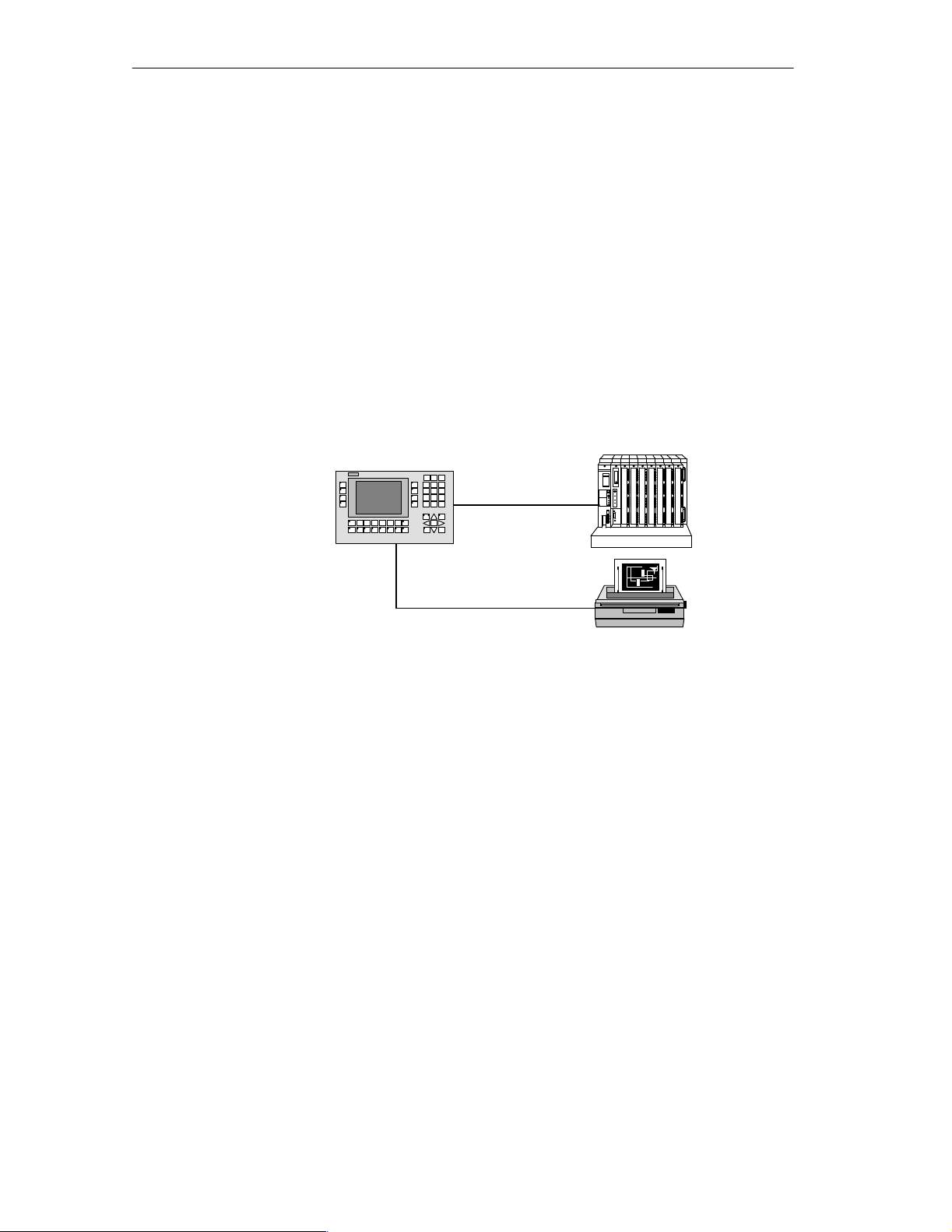
configuration
Operator panels OP25, OP35 and OP45 are panel mounting devices for use
locally on the machine.
Due to the high degree of protection (IP65 at the front panel), the OP is also
suitable for hostile industrial environments.
Possible installation locations for the OPs are:
Cabinets or panels
19” cabinets or racks (OP35 and OP45 only)
The OP’s integrated interfaces permit it to be connected directly to controllers.
A printer can also be added for hardcopies and listings.
Controller
OP25, OP35, OP45
Planning
Printer
A PC or programmer is used to configure the OP with ProT ool (a configuring
program which runs under Windows).
1-2
Equipment Manuel OP25, OP35, OP45
Release 04/96
Page 13
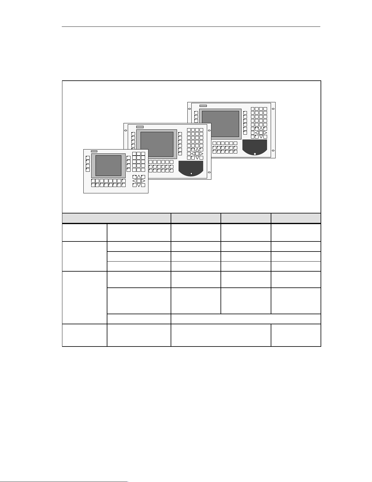
1.1 The Operator Panel at a Glance
OP45
OP35
OP25
Product Description
Basic Models OP25 OP35 OP45
Models Black and white display
Color display
Display
Sealed keyboard
Interfaces Serial interfaces for con-
Type STN-LCD STN-LCD TFT-LCD
Resolution (in pixels) 320 x 240 640 x 480 640 x 480
Background illumination Yes Yes Yes
System keys with fixed
functions
Function keys with confi-
gurable functions
Softkeys thereof 14 20 20
Function key labels Customized labelling with label strips
nection of controller,
PC/PG, printer
Yes
–
24
(4 with LED)
24
(18 with LED)
2 x V.24/TTY
1 x RS 422/RS 485
1 x TTY/RS 422/RS 485
Yes
Yes
32
(4 with LED)
36
(28 with LED)
–
Yes
32
(4 with LED)
36
(28 with LED)
1 x V.24/TTY
1 x V.24
1 x RS 485
Equipment Manuel OP25, OP35, OP45
Release 04/96
1-3
Page 14

Product Description
Basic Model OP25 OP35 OP45
Memory
Floppy disk drive – Optional Yes
Hard disk – – 425 Mbytes
Special features
Flash EPROM for firmware and user data
Working storage (DRAM) 2 Mbytes 4 Mbytes 8 Mbytes
Memory for configuration 1 Mbyte 3 Mbytes 5.5 Mbytes
Hardware clock (buffered) Yes Yes Yes
Relay output Yes Yes –
Operation of an external
MF2 keyboard
DOS operation – – Yes
Operation of an external
monitor
Module slot for PCMCIA/
JEIDA cards
1 Mbyte 2 Mbytes –
– – Yes
– – Yes
Yes Yes –
Options OP25 OP35 OP45
Direct key module Digital outputs, address-
able via either keys or configurable ports
Floppy disk drive – 3 ” drive (Included in stan-
Installation Possible in OP25 OP35 OP45
Switching cabinets/consoles Yes Yes Yes
19” cabinets/racks – Yes Yes
Controllers That Can Be Used OP25 OP35 OP45
SIMATIC S5 programmable controllers Yes Yes Yes
SIMATIC S7 automation system Yes Yes –
SIMATIC 500/505 Yes Yes –
PC/AT-compatible computers Yes Yes –
Controllers of other manufacturers Yes Yes –
8 16 16
dard model)
(AS 511 only)
1-4
Equipment Manuel OP25, OP35, OP45
Release 04/96
Page 15

1.2 Process Visualization and Manipulation
“One picture is worth a thousand words” goes the familiar saying.
This is particularly true of machine and system monitoring where it is impor-
tant to provide the operator with clear and easy-to-understand information
about the state of the process.
Product Description
Screens
Full graphic plant
screens
Bars, curves
Symbolic graphics
Process manipulation
Process values and process sequences are shown by screens which can contain graphics, texts and values. Process values in a system are often related
in some way. Screens show this relationship and thus represent an image of
the process.
The OP permits you to represent machines and plants as full graphic
screens. This improves operator orientation.
You can show current process values (e.g., filling level and speed) as numeric
values, or symbolically as text or bars.
Curves are a particularly good way to show changeable process values (e.g.,
changes in temperature) over a period of time.
Symbolic graphics are another way to indicate process values. Symbolic
graphics are graphic elements (i.e., bit maps) which are indicated alternately
to show different process states (e.g., valve open or closed).
The operator can use the OP’s integrated keyboard to intervene in the process
sequence.
For example, you can control actuators (e.g., valves) by specifying process
values (i.e., setpoints).
Features important to operator control include ease of handling, short training
periods, and a high degree of reliability.
You can configure the structure of the OP operating environment as desired
(i.e., you can tailor operator control to your particular application).
A few features:
Free configurable function keys
Softkeys
Pop-up windows for symbolic entries
Equipment Manuel OP25, OP35, OP45
Release 04/96
1-5
Page 16

Product Description
Messages
Information texts
Recipes
Password protection
Process or machine states (e.g., the current operating mode) are displayed by
the OP as plain-text event messages.
Alarm messages provide information on critical machine states.
Current measured values (e.g., temperatures, speeds, etc.) can also be in-
cluded in the text of event or alarm messages.
Event and alarm messages are stored with date and time in a message buffer.
At the same time, all event and alarm occurrences can be printed (if message
logging is switched on and a printer is connected).
Information texts can be configured. You can use them to give the operator
additional information which will help him/her to correct a malfunction.
Complete blocks of machine data can be stored as recipes on the OP.
The structure of a recipe is specified during the configuring phase. It makes
no difference whether the recipes are “real recipes” or only piece number
specifications, traversing paths or temperature progressions.
You can change or redefine recipe data directly on the OP.
The OP offers password protection. Each operator can be assigned a different password. A password level can then be used to enable or disable each
operator’s access to special operating functions. This prevents incorrect entries and improves system security.
Multiple languages
PG functions
All messages and texts for screens can be stored in the OP in up to three different languages.
This permits international use even when operating personnel speak different
languages.
The “STATUS/FORCE VARIABLE” PG functions are available for testing
and trouble-shooting. They can be used on the OP to specify and change
address areas in the controller. This makes on-site troubleshooting fast even
without a programmer.
1-6
Equipment Manuel OP25, OP35, OP45
Release 04/96
Page 17

Functionality
The functions of the operating panels are listed below. The numerical values
contained in the tables are the maximum values that can be managed by an
OP and are limited possibly only by the size of the user memory.
Functions OP25 OP35 OP45
Event messages Number 2000
Indication In message line/message window
View all queued events On message page
Length of message text (in char-
acters)
Lines per message 2 1 1
Process values in message text 8
Alarm messages Number 2000
Indication In message line/message window
Indication type 1st value/last value (can be selected)
View all queued alarms On message page
Length of message text (in char-
acters)
Lines per message 2 1 1
Process values in message text 8
Acknowledge single alarm mes-
sages
Acknowledge several alarm mes-
sages simultaneously
Message logging Logged on a printer Yes
Message buffer Capacity 512 message occurrences
Look at buffered event messages/
alarm messages
Delete Yes
Buffer overflow warning Yes
Forced printout for buffer over-
flow
2 x 35 70 70
2 x 35 70 70
Yes
Yes, 16 acknowledgement groups
On puffer page
Yes
2
Equipment Manuel OP25, OP35, OP45
Release 04/96
2-1
Page 18

Functionality
Functions OP25 OP35 OP45
Message acquisition Time of occurrence Date/time
Message status Arriving, departing, acknowledged
Screens Indicate Yes
Print (hardcopy) Yes
Static screen elements Static full graphics
Fixed text
Semigraphic characters
Input/output elements Input fields
Output fields
Combined input/output fields
Symbolic input
(pop-up window)
Symbolic output
(graphics/text)
Bars
Curves
Operator prompting Icons for softkey functions
Fixed window Yes
Limit value monitoring For inputs/outputs Yes
Conversion functions For inputs/outputs Linear
Square
Fonts Loadable fonts per language 3
Fonts not dependent on language
(with semigraphic characters)
Character sizes in pixels 8 x 8 to 64 x 64
Text attributes Display Flashing, inverse, underlined
Printer Bold, italics, underlined
Information texts Lines/characters 7/35
For messages Yes
For input fields Yes
For screens Yes
Password protection Number of passwords
Password levels
1
50
9
2-2
Equipment Manuel OP25, OP35, OP45
Release 04/96
Page 19

Functionality
Functions OP25 OP35 OP45
Recipes Number 255
Data records per recipe 500
Entries per data record 500
Save data records (set up) Controller/OP storage medium
Load data records Storage medium OP/controller
Delete data records In storage medium
Change data records (edit) In storage medium
Transfer current values Controller OP
OP controller
Transfer data records Data medium OP
OP data medium
Parameter records Yes
Print functions Hardcopy of the contents of the
display
Character mode (ASCII)
Graphic mode
Direct message logging Yes
Screen printout in character mode
(ASCII)
Data backup Backup/restore function for
PCMCIA/JEIDA cards
Online language switchover Number of languages 3
PG functions For SIMATIC S5 Yes Yes Yes
(Status/force variable)
For SIMATIC S7 Yes Yes Yes
Loop–through operation For PG or additional TD/OP
(only with SIMATIC S5 and
AS 511 protocol)
Display Setting for display brightness/
contrast
Blanking circuit Yes Yes –
Connection to PLC SIMATIC S5-AS511
SIMATIC S5-FAP
SIMATIC S5-L2-DP
SIMATIC S7-MPI
SIMATIC S7-PPI
SIMATIC 500/505
Free Serial
Allen Bradley
Mitsubishi
Telemecanique
Yes
Yes
Yes Yes –
Yes Yes –
Yes Yes No
Yes Yes –
Yes
Yes
Yes
Yes
Yes
Yes
Yes
Yes
Yes
Yes
Yes
Yes
Yes
Yes
Yes
Yes
Yes
3
3
3
Yes
Yes
Yes
3
3
3
Yes
–
No
–
–
–
–
–
–
–
2
2) The immunity to interference cannot be guaranteed on account of the hardware characteristics of the OP45
3) Driver available as an option
Equipment Manuel OP25, OP35, OP45
Release 04/96
2-3
Page 20

Functionality
2-4
Equipment Manuel OP25, OP35, OP45
Release 04/96
Page 21

FUNCTIONS OF THE
OPERATOR
3 Using the OP
4 Screens
5 Messages
6 Recipes
7 Print Functions
8 Password Protection
9 Status/Force Variable with the OP
PANEL
Part II
Equipment Manuel OP25, OP35, OP45
Release 04/96
ii-i
Page 22

ii-ii
Equipment Manuel OP25, OP35, OP45
Release 04/96
Page 23

Using the OP
3
Overview
Screen section
Fixed window
Processes (e.g., a machine tool, mixing station or similar) are displayed on the
OP with screens. The processes can also be manipulated.
One screen takes up the entire display. An example of a possible layout is
shown below.
Fixed window
Main screen area
Icons for softkey
functions
Figure 3-1 Screen layout for the OP25
The fixed window provides the operator with a continuous stream of important
process variables regardless of which screen is open at the moment.
Main screen area
Icons
Equipment Manuel OP25, OP35, OP45
Release 04/96
The main screen area contains the actual contents of the currently opened
screen.
Additional windows (e.g., message windows, help windows and pop-up windows) are faded in over the main screen area and the fixed window.
Icons symbolize softkey functions related to specific screens.
3-1
Page 24

Using the OP
3.1 Keyboard
Overview
Function keys/
softkeys
The keyboard of the OP is equipped with two blocks of keys:
The function keys/softkeys
The system keys
A function key always triggers the same action in the OP or controller (i.e.,
global significance for the OP) regardless of which screen is currently open.
A few possible actions are listed below.
Open a screen
Indicate the current alarm messages
Start a hardcopy of a screen
Indicate the time window
The term softkey means that function keys can have a meaning related to the
currently open screen (i.e., local).
The function of a softkey can vary from screen to screen. When a screen is
open, a softkey’s function is shown by an icon in the margin of the monitor
screen.
The following keys can have softkey functionality:
For OP25: F1 to F14
Repeat function
(for OP45 only)
For OP35/OP45: F1 to F20
The repeat function activates when a key is repeatedly pressed.
Note
Do not press several keys on the OP45 at the same time. This can cause incorrect entries.
3-2
Equipment Manuel OP25, OP35, OP45
Release 04/96
Page 25
Using the OP
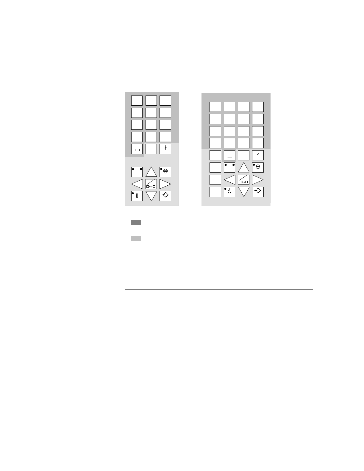
System keys
The system keys are used to make entries on the OP.
Figure 3-2 shows the system keyboard for the OP25 and OP35/OP45.
OP25
AB8CD9EF
7
GH5IJ6KL
4
MN2OP3QR
1
ST0UV
.
YZ
A–Z
HELP
A–Z
INS
DEL
WX
+/–
ESC
ACK
ENTER
= Input keys for numeric and alphanumeric characters
OP35/OP45
AB7CD8EF9GH
/
IJ4KL5MN6OP
*
QR1ST2UV3WX
–
YZ.:\0=,
+
TAB
ALT
A–Z
A–Z
CTRL
SHIFT
HELP
A–Z
INS
DEL
()
+/–
ESC
ACK
ENTER
= Control keys
Figure 3-2 Assignment of the system keys
Note
The TAB, ALT, CTRL and SHIFT keys of the OP35 have no function.
Equipment Manuel OP25, OP35, OP45
Release 04/96
3-3
Page 26

Using the OP
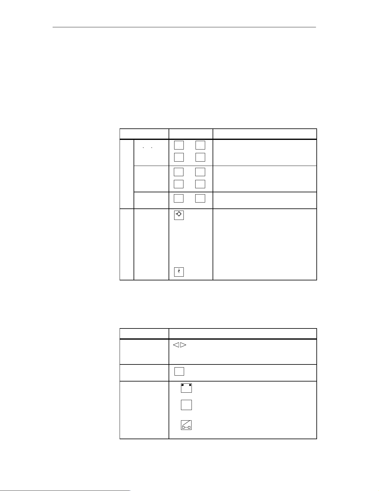
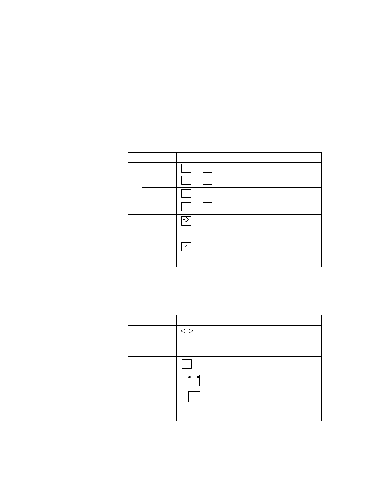
Key functions
The control keys of the OP have the following functions:
Key Description
A–Z
Shift key
This key is used to shift the input keys from numeric to
alphanumeric.
The key is equipped with two LEDs which indicate the
current status.
No LED is on.
Numeric assignment of the input keys is active.
Alphanumeric assignment of the input keys becomes
active when this key is pressed once.
One of the two LEDs (i.e., left or right) is on.
Left or right alphanumeric assignment of the input
keys is active.
Input key assignment alternates between the left and
right alphanumeric assignment each time this key is
pressed.
A–Z
A–Z
Switches the active window (OP25/OP35 only)
Switch from alphanumeric assignment of the input
keys back to numeric assignment
INS
DEL
ESC
Cancel key
Activates edit mode (OP25/OP35 only)
Deletes/inserts single characters
This key cancels already started actions. Some examples
are listed below.
Delete an already entered character for a value input
Delete a queued system message
Acknow-
ACK
ledgement
key
Info key
HELP
Apply key
ENTER
Cursor keys Move the cursor to the individual input fields in a
This key acknowledges the currently indicated alarm
message or all messages of an acknowledgement group.
The LED remains on as long as an unacknowledged
alarm message is queued.
This key is used to open a window containing a help text
for the selected object (e.g., message, input field).
The LED goes on when a help text is available for the
selected object.
The help window is closed by pressing any key.
Accept and exit an entry
Open the pop-up window for a symbolic entry
screen
Move the cursor within an input field
Select an entry from the message buffer
Select a value from the pop-up window
3-4
Equipment Manuel OP25, OP35, OP45
Release 04/96
Page 27

3.2 Input/Output Fields
Using the OP
Overview
Procedure
Correcting/canceling entries
The screens on the OP contain different types of input/output fields.
Numeric fields (digital or analog)
String fields
Symbolic fields
Values can be entered on the OP in these input fields which are then transferred
to the controller.
The basic procedure for entering values on the OP is described below.
1. Using the cursor keys, position the cursor on the desired input field.
2. Enter the value. The method of entry varies depending on the type of field.
See the following subsections for information on handling the individual
fields.
3. Confirm the entry with with ENTER key.
The following methods of correction are available before the entry is applied.
Using the INS/DEL key, insert/delete single characters where the cursor is
positioned. Then use the ENTER key to confirm the correct value.
Cancel the entry with the ESC key.
Edit mode
(OP25/35 only)
The original value is then automatically rewritten in the field. Enter the
correct value, and confirm with the ENTER key.
An edit function is available on the OP25/35. This edit function can be used to
edit entries which have already been applied.
1. Position the cursor on the desired input field.
2. Activate edit mode by pressing the INS/DEL key.
In contrast to input mode, the indicated value is retained.
3. Move the cursor to the appropriate position of the input field.
4. Using the INS/DEL key, insert/delete characters where the cursor is positioned.
5. Confirm the entry with the ENTRY key.
The entry can be canceled with the ESC key. The old value is indicated
again.
Equipment Manuel OP25, OP35, OP45
Release 04/96
3-5
Page 28
90
Using the OP
3.2.1 Numeric Fields
The shape of the cursor changes in input mode. Input starts at the right-hand
edge of the input field. Digits are shifted to the left similar to a pocket calculator.
Entry
T o make entries in a numeric field, proceed as follows:
Step Key Description
1 Enter deci-
mal value
Enter
hexadecimal
value
Enter digital
value
2Apply entry
Or
Cancel entry
+/–
ST
AB EF
S
01
ENTER
ESC
90
to
.
,
to
90
to
,
The characters A to F must be entered in
alpha mode.
The entered value becomes valid.
The entry becomes invalid if the en-
tered value violates a configured limit
value or an incorrect entry is made.
The “old” value is retained.
The “old” value becomes valid again.
Correction
If you have made a mistake and have not yet applied the entry, proceed as follows:
IF ... THEN ...
Position the cursor on the digit and over-
Wrong digit
One digit too
many
1. Switch to alpha mode.
One digit too few
2. Inserts a blank where the cursor is positioned and
3. Shift back to numeric assignment of the input keys.
4. Overwrite blank.
3-6
write.
(The cursor remains on this position.)
INS
Deletes the digit at the cursor position and
DEL
consolidates the input from the left.
A–Z
INS
DEL
shifts the entry to the left starting at the cursor
position.
A–Z
A–Z
Equipment Manuel OP25, OP35, OP45
Release 04/96
Page 29
3.2.2 String Fields
Both numeric characters (i.e., digits) and alphanumeric characters (i.e., letters
of the alphabet) can be entered in a string field. Strings may also contain
blanks.
The cursor changes shape in input mode. The entry starts at the left edge of the
input field. The cursor jumps one position to the right each time a character is
entered.
Using the OP
Entry
Correction
T o make entries in a string field, proceed as follows:
Step Key Description
1
Enter digits
Enter letters
2 Apply entry
to
+/–
,
A–Z
ST
AB Y
to
ENTER
If necessary, switch back from alpha mode.
90
.
Switch to alpha mode.
Z
The entered string becomes valid.
Switch back from alpha mode
4
Or
Cancel entry
ESC
The input cursor is deleted.
Switch back from alpha mode
1
The “old” string becomes valid again.
If you have made a mistake and have not yet accepted the entry, proceed as
follows:
Wrong character
One character too
many
One character too
few
4) Not applicable to OP45
Equipment Manuel OP25, OP35, OP45
Release 04/96
IF ... THEN ...
Position the cursor on the character and
overwrite.
(The cursor jumps one position to the right
after the overwrite.)
INS
Deletes the character at the cursor position
DEL
and consolidates the input from the right.
1. Switch to alpha mode.
A–Z
INS
2. Inserts a blank where the cursor is
DEL
positioned and shifts the entry to the
right starting at the cursor position.
3. Overwrite blank.
3-7
Page 30
Using the OP
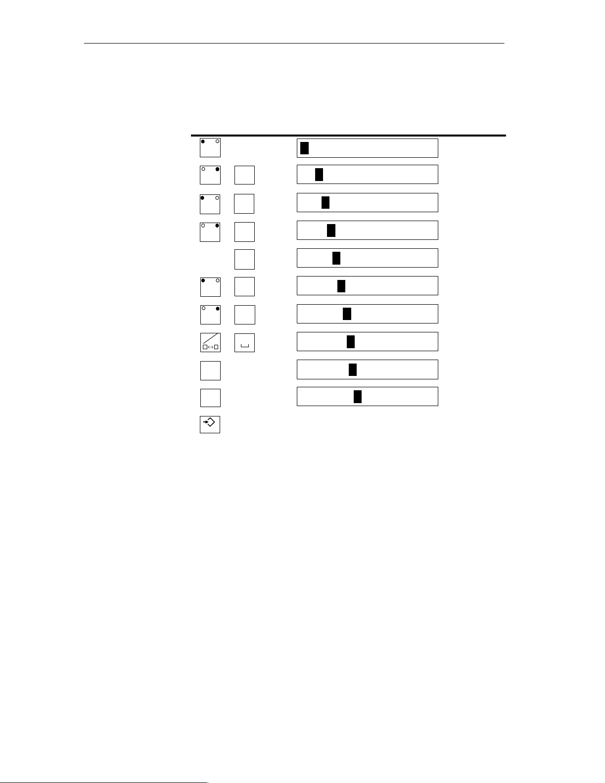
Example of a
string entry
You want to enter “valve 05”. Proceed as follows:
Key Display
A–Z
A–Z
A–Z
A–Z
A–Z
A–Z
A–Z
UV
,
EF
,
MN
,
ST
IJ
,
KL
,
,
0
V
VA
VAL
VALV
VALVE
VALVE
VALVE
VALVE 0
5
ENTER
VALVE 05
Apply entry .
3-8
Equipment Manuel OP25, OP35, OP45
Release 04/96
Page 31

3.2.3 Symbolic Fields
1
Open pop-up
indo
ENTER
Entries in symbolic fields are made with a pop-up window indicating the entries available for this field.
Using the OP
Entry
Example
T o make an entry in a symbolic field, proceed as follows:
Step Key Description
1 O
en o-u
w
w
2 Select entry
3 Apply entry
ENTER
ENTER
The value belonging to the selected
entry becomes valid.
The pop-up window is closed.
Or
Cancel entry
ESC
You want to use a symbolic entry to turn on mixer 3.
The pop-up window appears.
ENTER
The “old” value becomes valid again.
The pop-up window is closed.
ENTER
Equipment Manuel OP25, OP35, OP45
Release 04/96
Mixer 3 is marked “off”.
–
Off
On
You select mixer 3 “on”.
–
Off
On
The entry you selected is applied (i.e., accepted).
3-9
Page 32

Using the OP
3.3 Using the Windows of OP25/OP35
Several windows can be displayed at the same time on the OP.
T o use them, you can switch between the individual windows.
Switches between the following windows are possible.
Main screen
Fixed screen
Message line and message window
Selecting a window
Restrictions/
special features
Information key
Use the middle cursor key to select the window in which you want to work or
make entries.
Key Description
A–Z
A–Z
Each time you press this key the cursor jumps from one
window to the next.
The window in which the cursor is located is the active window (i.e., you can
make entries or perform other operations in this window).
You cannot switch to windows which do not contain input fields.
Exceptions: Message line, message window and message page
For these exceptions, the cursor is positioned on the first message. You can
then select the information text pertaining to the message.
How to use the information key
The first time the key is pressed
The information text pertaining to the selected field or message is displayed.
3-10
The second time the key is pressed
The information text pertaining to the main screen is displayed.
Equipment Manuel OP25, OP35, OP45
Release 04/96
Page 33

Using the OP
Static and dynamic
windows
The position of the displayed window is static on the OP25.
When an alarm message window or a pop-up window is displayed, for exam-
ple, an entry field hidden by the window cannot be used.
Generally , entries on the OP25 cannot be made unless all windows are closed.
The OP35 can be configured with dynamic window positioning.
When a window is to be displayed, it jumps automatically to a position which
does not cover up the input field or the cursor.
This means that entries can always be made regardless of the contents of the
display .
Equipment Manuel OP25, OP35, OP45
Release 04/96
3-11
Page 34

Using the OP
3-12
Equipment Manuel OP25, OP35, OP45
Release 04/96
Page 35

Screens
4
Overview
Logically related process values are combined into screens. Graphic elements
illustrate the relationships between these values. The individual screens provide a quick overview of a process or a system. In addition to showing what is
happening in the process, screens can also be used to control the process by
entering new process values.
Equipment Manuel OP25, OP35, OP45
Release 04/96
4-1
Page 36

Screens
4.1 The Operator Panel in Action
The OP is to control and monitor a plant which mixes and bottles various fruit
juices. Plant functions are divided roughly into the mixing and bottling stations.
Mixing station
Bottling station
The ingredients for the juices are stored in three tanks. The ingredients are
mixed in certain proportions depending on which fruit juice is to be produced.
After the juice is mixed, a valve is opened, and the finished fruit juice flows
into a filling tank and is then bottled. The bottles are transported on a conveyor belt. Before being filled, they are checked for glass breakage. After
being filled, the bottles are sealed, labelled and palletized.
TANK1 TANK2 TANK3
To the bottling station
MIXER
M
4-2
Equipment Manuel OP25, OP35, OP45
Release 04/96
Page 37

From
the mixer
Screens
Bottling station
Labelling
Figure 4-1 Mixing and bottling stations
Palletization
Equipment Manuel OP25, OP35, OP45
Release 04/96
4-3
Page 38

Screens
4.2 Screen Elements
Screens on the OP are made up of various screen elements. Some examples
are listed below.
Fixed texts
Semigraphic characters
Input fields for process values
Output fields for process values
Bars
Curves
Symbolic graphics
We will use the mixing station of the fruit juice plant to show you the various
screen elements.
Screen elements of
the sample screen
The screen might look something like this.
Mixing Station
1
3
6
Tank 1 Tank 2 Tank 3
Amount in
the mixer
(in l)
44
Valve 4
open
1
Fixed text
2
Semi-graphic (corresponding to tank)
3
Bar shows filling level of the tank graphically.
4
Symbolic input field to open and close the valve
5
Symbolic graphic shows the status of the valve (i.e., open or closed)
6
Numeric output field
7
Icons for the softkey functions
Valve 4
closed
Ingredients (in l)
Mixer mo-
Mixer
motor
on
tor
off
Selection
bottling station
2
4
5
Valve 4
7
Selection
main screen
4-4
Figure 4-2 Sample screen for a mixing station
Equipment Manuel OP25, OP35, OP45
Release 04/96
Page 39

4.3 Selecting a Screen
You can select a screen in the following ways.
Via function key (softkey)
Via an appropriately configured input field
Via job from the controller
Screens
Via function key
Via input field
Via job from the
controller
You can open a certain screen by pressing a function key (or a softkey).
A screen is opened after an entry has been executed in an input field configured for the selection of this screen.
When the state of the process/plant requires, the controller causes a screen to
be selected on the OP.
Equipment Manuel OP25, OP35, OP45
Release 04/96
4-5
Page 40

Screens
4.4 Standard Screens
The OP comes already equipped with standard screens. You can use these
standard screens for your configuration, or adapt them to fit your application.
Main screen
The standard screens are called from a main screen via softkey.
Main screen
Softkeys for
selecting
the standard
1
2 3 4 5 6
Figure 4-3 Main screen (example)
1
Password processing
2
Printer settings
3
Status Variable
4
System settings
screens
4-6
5
Message processing
6
Mixing station (our example)
For detailed information on function and use of the standard screens, see the
applicable sections in this manual.
Equipment Manuel OP25, OP35, OP45
Release 04/96
Page 41

Messages
5
Messages inform the operator of certain occurrences by displaying a text.
There are three types of messages.
Event messages indicate process states during normal operation of the sys-
tem.
Alarm messages indicate malfunctions/interruptions in the process.
System messages
In contrast to event and alarm messages which contain process-related information, system messages provide information on internal operating
states/errors of the OP.
Equipment Manuel OP25, OP35, OP45
Release 04/96
5-1
Page 42

Messages
5.1 Event and Alarm Messages
Event and alarm messages provide information on normal or critical process
states by indicating message texts. The message texts may also contain current
measured values.
Below are two examples showing the differences between event and alarm
messages.
Event messages
Alarm messages
The fruit juice plant has finished a mixing procedure. An event message informs the operator of this. The event message might look something like this:
Mixing procedure finished
Juice in the mixer: 5000 l
The operator would now like to start the bottling procedure but has forgotten to
open the filling valve. The controller automatically stops the bottling procedure and outputs an alarm message. The alarm message might look something
like this:
Bottling procedure terminated
Filling valve is closed !
Because of their urgency, alarm messages must be acknowledged to ensure that
the operator has noticed the message.
Acknowledgement can also be performed by the controller.
5-2
Equipment Manuel OP25, OP35, OP45
Release 04/96
Page 43

5.1.1 General Features
Messages
Available methods
of indication
Message line,
message window
The OP offers the following ways to indicate event and alarm messages.
You can indicate a current event or alarm message in a message line or in a
message window.
You can configure one of the following combinations:
Indicate an event or alarm
message in the message line
Indicate an event message in
the message line and an
alarm message in the message window
Message line
Event or alarm message
Message line
Event message
Alarm message window
Alarm message
Indicate an event/alarm mes-
sage in the appropriate message window
Event message window
Alarm message window
Event message
page, alarm
The operator can look at all still queued event messages or alarm messages on
the appropriate message page.
message page
The OP stores all messages in a battery-buffered memory. The operator can
Message buffer
look at these stored messages.
Indication priorities
Each message is given a priority during configuration. This priority determines the importance of the message.
When several messages are queued, the message with the highest priority is
indicated first.
When several, unacknowledged alarm messages are queued, either the first
(i.e., the oldest) or the last (i.e., the latest) message is indicated.
The operator can change the configured type of indication (first/last).
When several event messages with the same priority are queued, the latest
is indicated.
Equipment Manuel OP25, OP35, OP45
Release 04/96
5-3
Page 44

Messages
Message states
Message indicator
Acknowledging
alarm messages
Message occurrences may assume the following states:
Arriving Marks the occurrence of the message
Departed Cause of the message no longer exists.
Acknowledged Only for alarm messages.
The operator or the controller has recognized the message
and confirmed it.
The OP acquires these message states with the precise time and outputs them
when a message page or the message buffer is indicated.
At least one alarm message is still queued when this symbol appears on the
OP’s display.
Alarm messages must be acknowledged by either the operator or the controller.
Acknowledgement
groups
Key Description
Acknowledge indicated alarm message
ACK
After acknowledgement, the next unacknowledged message (if one exists) is
then faded in.
You can combine messages into acknowledgement groups.
When the indicated message belongs to an acknowledgement group, its ac-
knowledgement automatically acknowledges all other alarm messages of this
acknowledgement group.
5-4
Equipment Manuel OP25, OP35, OP45
Release 04/96
Page 45

5.1.2 Current Messages
Messages
Message line
Flashing alarm
messages
Priorities of indication
The message line is always present regardless of which screen is selected.
Depending on your configuration, event messages and/or alarm messages are
displayed in the message line.
Example of an event message:
Mixing procedure finished
Juice in mixer: 5000 l
Process value at the time of arrival
Alarm messages flash to distinguish them from event messages.
Alarm messages
Event messages
Alarm messages always take precedence
over event messages.
Event messages are not indicated unless no
more alarm messages are queued and all
have been acknowledged.
Message window
Standby
message
A standby message is indicated when no
event messages are queued.
In addition to the message text, messages in a message window contain other
information (e.g., message number and date/time of the arrival of a message).
Example of an alarm message window:
Message number Date
Time
Acknowledge–
ment group
Number of unacknowledged messages
0048 11:34:02 11.11.93 QGR.01 2
Tank 25: Temperature 156 degrees
Call shift supervisor: Tel: 9465
Process value at time of arrival
Equipment Manuel OP25, OP35, OP45
Release 04/96
5-5
Page 46

Messages
Event message
window
Alarm message
page,
event message
page
The event message window is not automatically faded in. It must be selected
by the operator or the controller and then deselected again later.
A standby message is displayed when no current event message is queued.
Message number Date
Time
i
Number of not departed
messages
0050 11:42:17 11.11.93 12
Tank 25: Temperature within tol.
again 94 degrees
Process value at time of arrival
The message pages give the operator an overview of the still queued (i.e., not
yet departed) alarm or event messages.
The event message page or the alarm message page can be selected on the OP
or via the controller.
The individual message occurrences are sorted by indication priority and, if
alarm messages, listed by first/last setting.
Example of an alarm message page:
Alarm Message Page
0049 K 11:32:00 11.18.93 QGR:01
Tank press. too high: 12.7 bar
0049 KQ 11:33:20 11.18.93 QGR:01
Tank press. too high: 10.3 bar
0010 K 11:34:36 11.18.93 QGR:02
Oil feed stopped!
0010 KQ 11:35:18 11.18.93 QGR:02
Oil feed stopped!
Message status:
K = arrived,
Q = acknowledged
Message number
Time and date of arrival
Process value
at time of arrival
Acknowledgement
group
If all messages do not fit on the display at the same time, you can scroll the
contents of the message page up/down with the
, cursor keys.
5-6
Equipment Manuel OP25, OP35, OP45
Release 04/96
Page 47

Messages
The message page contains the following information for each message occurrence.
Message number
Message status with date and time
The OP updates the message status display (e.g., K for arriving, Q for
acknowledged).
Acknowledgement group to which an alarm message belongs
Message text, with process values if applicable
When a message contains process values, the OP indicates these values as
they were when the state occurred or stopped occurring (i.e., time of arrival
or time of departure).
The OP does not acquire current process values after the message has been
acknowledged.
To message buffer
and back
Message logging
You can switch back and forth between indication of the message page and the
message buffer by repeatedly pressing the function key which you used to call
the alarm message page/event message page.
All message occurrences are logged directly on a printer (if message logging is
switched on and a printer is connected).
Equipment Manuel OP25, OP35, OP45
Release 04/96
5-7
Page 48

Messages
5.1.3 Stored Messages
The OP stores all message occurrences in a battery-buffered memory.
This allows you to indicate the messages at a later time.
Alarm message
buffer, event
message buffer
The stored message occurrences are indicated in the alarm message buffer or
the event message buffer depending on what type of message they are.
A buffer page can be selected on the OP or via the controller.
All messages are indicated in the order of when they occurred. The latest
message is shown at the top of the display.
Example of indicating the alarm message buffer:
Alarm Message Buffer
0010 KGQ11:38:04 11.18.93 QGR:02
Oil feed stopped!
0010 KQ 11:35:18 11.18.93 QGR:02
Oil feed stopped!
0049 KGQ11:34:09 11.18.93 QGR:01
Tank press. too high: 9.3 bar
0049 KQ 11:33:20 11.18.93 QGR:01
Tank press. too high: 10.3 bar
0049 K 11:32:00 11.18.93 QGR:01
Tank press. too high: 12.7 bar
Message status:
K = arrived,
G = departed,
Q = acknowledged
Message number
Time and date of arrival
Process
value
Acknowledgement
group
Deleting the buffer
5-8
If a message text contains process values, the OP indicates these values as they
were when the message occurrence arrived and departed.
Otherwise, the information is identical to that of the event message page or
alarm message page.
The event message buffer/alarm message buffer can be deleted by operator
input on the OP or via the controller.
Exceptions:
Queued messages
Not yet acknowledged alarm messages
Equipment Manuel OP25, OP35, OP45
Release 04/96
Page 49

Messages
Buffer overflow
The OP stores message occurrences in a common memory area for event and
alarm messages (i.e., the so-called message buffer).
If there is only a certain amount of memory space left in the message buffer
(i.e., remaining buffer space), the OP can fade in a system message to that effect.
If there is no space left in the message buffer and new messages arrive, the OP
continues deleting message occurrences from the message buffer until a certain
remaining buffer space is available again.
The oldest message occurrences are deleted in the following order.
1. Event messages which have already departed
2. Alarm messages which have departed and have been acknowledged
3. Event messages which are queued
4. Alarm messages which are queued
A forced printout of the deleted messages is made (if overflow was configured
as on, and a printer is connected).
Equipment Manuel OP25, OP35, OP45
Release 04/96
5-9
Page 50

Messages
5.1.4 Standard Screen: Message Processing
Layout
Uses
Event and alarm messages can be processed with the standard screen Message
Processing.
Message Processing
ESC
1 2 3
Softkeys
Return to main
screen
Figure 5-1 Standard screen: Message Processing
The softkeys have the following meaning:
1
Open event message window
2
Delete event message buffer
3
Delete alarm message buffer
In addition, the following functions can be selected via function keys.
Open event message page, alternate between indicating the event
K1
message page and the event message buffer
Open alarm message page, alternate between indicating the alarm
K2
message page and the alarm message buffer
5-10
Equipment Manuel OP25, OP35, OP45
Release 04/96
Page 51

5.2 System Messages
System messages inform you of certain internal operating states of the OP.
The messages include everything from informational notes to serious and fatal
error messages.
System messages can be caused by the following:
Operator errors
(e.g., illegal entries)
System errors
(e.g., disturbed communication between OP and controller)
Messages
System message
window
Deselecting
As soon as a certain operating state/error occurs, the OP automatically fades in
a window containing a system message.
Example of a system message window:
Message number
i
210 Buffer overflow warning
A system message consists of a message number and a message text. The message text can also contain internal system variables which help to localize the
cause of the error message.
Some system messages expect a confirmation from or a decision by the operator. For example:
“Format data medium? 0 Yes/ 1 No”
The entry of 0 (yes) or 1 (no) then determines what happens next.
The system message window can be closed by pressing the cancel key or by
selecting another screen.
Error causes,
remedies
The appendix of this manual contains a list of system messages including additional information on the cause of the message and any system variables indicated. In some cases, possible remedies are also shown.
Equipment Manuel OP25, OP35, OP45
Release 04/96
5-11
Page 52

Messages
5-12
Equipment Manuel OP25, OP35, OP45
Release 04/96
Page 53

Recipes
6
Our fruit juice plant was introduced in section 4 of this manual. The finished
product of our fruit juice plant is a bottle of fruit juice.
The finished product (i.e., a bottle of fruit juice) is determined by the various
variables of the system.
You can combine the variables for one type of juice into a set of “processing
instructions”. This set of “instructions” is called a recipe. The individual variables are called recipe entries. Recipes are configured and cannot be changed
on the OP.
Equipment Manuel OP25, OP35, OP45
Release 04/96
6-1
Page 54

Recipes
Example of
a recipe
Data records
We will call our recipe “ORANGE”.
Tank 1
Tank 2
Mixing time
Bottle size
Label
Bottles per case
One type of juice can be mixed in different concentrations to make orange
“drink”, orange “nectar” or “pure” orange juice, for example. The juice can
then be bottled in different-sized containers. All this is performed with the
same recipe but using different values for the individual entries. Related values for the entries (e.g., for the orange drink) are combined into a data record.
The data records for a recipe are put together on the OP. An example of how
they could appear is shown below.
Data Records For
“ORANGE” Recipe
Drink Nectar Juice
Tank 1
Tank 2
Mixing time
Bottle size
Label
Bottles per case
90
10
5
1
4
6
70
30
10
0.7
2
12
0
100
0
1
1
6
6-2
Equipment Manuel OP25, OP35, OP45
Release 04/96
Page 55

Recipes
Analogy of a file
cabinet
A file cabinet is a good way to illustrate how recipes function.
The file cabinet is the plant or the process to be controlled. Each of the indi-
vidual drawers represents the fixed structure of one recipe. Index cards in the
drawer contain the data records for that recipe.
Fruit Juice Plant
GRAPEFRUIT
LEMON
.......
Juice
Nectar
Drink
ORANGE
The operator uses the operator panel to “handle the index cards”.
We will now show you how to do this in the following subsections.
Equipment Manuel OP25, OP35, OP45
Release 04/96
6-3
Page 56

Recipes
6.1 Processing and Transferring the Data Records
Up to now, you have learned that the recipe and its entries are configured and
that you cannot change the recipes with the OP later on.
Thus, handling of the recipes with the operator panel is limited to the following
operations on the data records.
Store (set up)
Load
Delete
Edit
6-4
Equipment Manuel OP25, OP35, OP45
Release 04/96
Page 57

Recipes
6.1.1 Standard Screens: Data Record Processing and Data Record Transferring
The standard screen Data Record Pr ocessing is available for processing data
records. A second standard screen called Data Record Transmission provides
you with special transmission functions.
Data record
processing screen
Layout of the “Data Record Processing” Standard Screen
Data Record Processing
Recipe:
Data record name:
Comments:
Storage medium:
ORANGE
Drink
(T ext)
Int. Flash
Format
ESC
Symbolic input
String input
Symbolic input
Softkeys
Figure 6-1 Standard Screen: Data record processing
The icons in the softkey bar have the following meaning:
Softkey Description
A-Z
SAVE
Copy the current values from the PLC to the OP and store
them as a data record on the required storage medium
( Chap. 13):
OP25/35: internal flash memory or Jeida / PCMCIA-
module
OP35/45: floppy disk
OP45: hard disk
A-Z
A-Z
A-Z
A-Z
LOAD
DELETE
EDIT
SELECT
Load the selected data record from the selected storage
medium in the OP and transfer to the controller
Delete the selected data record from the selected storage
medium
Note:
If you want to delete all data records, it is easier to just
reformat the FLASH memory or floppy disk.
Edit (change) the selected data record on the selected
storage medium
Select a data record from the selected recipe
Equipment Manuel OP25, OP35, OP45
Release 04/96
6-5
Page 58

Recipes
Data record transmission screen
You can transfer the current values back and forth between the OP and the controller without storing the values on a data medium. This makes process startups easier, for example.
Transmission between OP and data medium is also possible.
The Data Record Transmission screen is available for these transmissions.
Data Record Transmission
Recipe:
Data record name:
Comment:
Data medium:
ORANGE
Drink
(Text)
Int. Flash
ESC
Symbolic entry
String entry
Symbolic entry
Softkeys
Figure 6-2 Example of a data record transmission screen
The icons in the softkey bar have the following meaning:
Softkey Description
SPS OP
OP SPS
Dat OP
OP Dat
SELECT
Transfer the current values from the controller to
the OP (update values in the OP)
Transfer the current values from the OP to the controller (transfer values to the controller)
Transfer a data record from the data medium to the
OP
Transfer a data record from the OP to the data medium
Select a data record name
6-6
Equipment Manuel OP25, OP35, OP45
Release 04/96
Page 59

Recipes
General use
Step Key/
1 Select recipe
name
2
Entering data
record names
or
Select data
record name
The following table shows you how to use the standard screens “Data Record
Processing” and “Data Record Transmission”.
Description
Softkey
Adhere to the following conventions when assigning data record names.
Names may not contain more than 11 characters.
After the eighth character is entered, a period is inserted automatically.
After the period, up to three characters can still be entered.
Special characters, blanks and commas may not be used.
A-Z
Activating the softkey causes a window to appear indicating all
data records of the selected recipe.
ORANGE
Drinks 05.10 11:34 Commentary
Nectar 05.12 20:17 Commentary
Juice 05.13 08:56 Commentary
Recipe
Data record
name
Time and date of the last storage/
change
Using the data record selection window:
3 Select data me-
dium
1. Select the desired data record with the cursor
2. Accept selected data record, and close window.
Data records can be stored/archived on the following data mediums to the ex-
tent that the OP is equipped with these:
keys.
ENTER
,
Internal FLASH, floppy disk, hard disk and PCMCIA/JEIDA card
4 With the softkey, select the function to be executed (e.g., load, save, and edit).
Equipment Manuel OP25, OP35, OP45
Release 04/96
6-7
Page 60

Recipes
6.1.2 Setting Up and Editing Data Records
Only the recipe structure is specified during configuration of the OP. No data
records exist yet. These are generated/set up on the OP.
Setting up/editing
data records
The standard screen called Data Record Pr ocessing contains an edit function.
You can use this function to accomplish the following.
Set up new data records on a selected data medium
Change the contents of data records stored on a data medium
T o set up/edit data records, proceed as follows.
1. Select recipe.
2. Enter data record names.
If you are setting up a new data record, enter a data record name which
does not exist yet.
3. Select data medium on which the data record is to be stored.
Note
The data medium must be formatted before data are stored on it for the first
time.
The screen called Data Record Pr ocessing contains a format function which
you can use to format flash disks and diskettes.
4. Select edit mode.
6-8
The data record which you have selected is shown as a list in the edit window (i.e., each line contains one recipe entry and value).
ORANGE Drink
Tank 1
Tank 2
Mixing time
Bottle size
Label
Bottles per case
Figure 6-3 Data record in the edit window
Comments
90
10
5
1
4
6
Equipment Manuel OP25, OP35, OP45
Release 04/96
Page 61

Using the edit window:
Step Key Description
1 Select the
value to be
changed.
2 Enter new
value.
3 Enter commen-
tary (optional).
Recipes
,
Only decimal numbers and strings are permissible.
Starting from the top input field, you can reach
the commentary field with the cursor key.
Note
Comments entered in the data record transmission screen are not included in the edit
window.
4 Accept new
values.
Or cancel
entry
ENTER
ESC
A safety prompt appears.
0 Yes: New values will be entered in the data
record and the edit window closed.
1 No: Continue to use edit window.
A safety prompt appears.
Equipment Manuel OP25, OP35, OP45
Release 04/96
6-9
Page 62

Recipes
Accepting values
from the controller
If you want your data records to contain the current values from the controller,
perform the following steps in the Data Record Pr ocessing screen.
1. Select recipe to which a data record is to be assigned.
2. Enter data record name and commentary (commentary is optional).
3. Select data medium on which you want the data record stored.
4. Store the data record.
The current values from the controller will now be transferred to the OP
and stored as a data record on the data medium you have selected. The
time at which the storage took place is also included.
Note
If the recipe does not yet contain a data record with the same name, the record
is stored immediately.
Otherwise, you will be asked if you really want to store the record before it is
overwritten.
5. T o set up additional data records, repeat steps 1 to 4 for each data record.
Copying data
records
Copying means that you use the current values in the OP as your basis, and
transfer these values to the data medium under different data record names.
You can then edit/adjust these data records later.
Proceed as described below in the Data Record Transmission screen.
1. Select recipe.
2. Enter data record name and commentary (commentary is optional).
3. Transfer data record from the OP to the data medium.
4. Repeat steps 1 to 3 for each new data record.
6-10
Equipment Manuel OP25, OP35, OP45
Release 04/96
Page 63

6.2 Parameter Records
Recipes
Definition
Example
Processing
The parameter record is a combination of one data record each from various
recipes with a common name.
The data records of a parameter record contain all values required to set a machine or plant. For example, you can use a parameter record to load the basic
settings for machines which are identically equipped but produce different
products.
We will now expand our example of a fruit juice plant to include three identically equipped production lines. The recipes ORANGE, GRAPEFRUIT and
LEMON are run parallel on these production lines. Each of the recipes contains a “drink” data record. These three data records make up the parameter
record called “drink”.
At the beginning of a shift, for example, each of the three production lines
must be set to produce a special drink. You can do this with just one load operation.
A parameter record is processed in the Data Record Pr ocessing screen in the
same manner as a data record.
The following can be performed on a parameter record.
Select
Selection
Store (set up)
Load
Delete
Parameter record must be selected as the recipe name in the Recipe: symbolic
field.
Note
When parameter record” is selected as the recipe, all data records of all
recipes are indicated after the SELECT softkey is pressed in the data record
selection window.
Parameter records (data records which exist more than once with the same
name) are identified with an asterisk (*) preceding the name.
Equipment Manuel OP25, OP35, OP45
Release 04/96
6-11
Page 64

Recipes
Saving (setting up)
Load
There are two ways to set up (i.e., to save on data medium) a parameter record
in the Data Record Pr ocessing screen.
a) Save a data record for each recipe.
1. Select Parameter Record as recipe.
2. Specify data record name and data medium.
3. Save parameter record the same as a data record.
b) Store a data record individually for recipe selected.
1. Select recipe name.
2. Specify data record name and data medium.
3. Save data record.
4. Repeat steps 1 and 3 for each data record.
All data records with the selected name on the data medium are loaded to the
OP, and then to the controller.
Use the procedure described in section 6.1.1.
Note
Depending on the scope of the recipes, it may require a relatively long period
of time to transfer a parameter record to the controller. For this reason, a parameter record should only contain those recipes which are absolutely necessary .
Delete
Edit
6-12
Complete parameter record:
Use procedure described in section 6.1.1.
Select Parameter Record as the recipe name.
Part of a parameter record:
Delete the desired data record individually from the selected
recipe.
Use procedure described in section 6.1.1.
A parameter record cannot be edited.
Only the individual data records within the parameter record can be edited.
Use procedure described in section 6.1.2.
Equipment Manuel OP25, OP35, OP45
Release 04/96
Page 65

Print Functions
The OP can perform the following functions on a printer.
Log messages
Make hardcopies of the contents of the current display
Hardcopy and message logging can be performed at the same time. When a
new print job is triggered while another print procedure is already running, the
new print job is buffered.
Suitable printers include the DR 215 and DR 235, for example.
7
Equipment Manuel OP25, OP35, OP45
Release 04/96
7-1
Page 66

Print Functions
7.1 Hardcopy
Trigger
Cancel
The hardcopy is triggered by pressing a function key. The screen indicated on
the display is then printed as characters (ASCII) or as pixel graphics. Windows currently opened in the screen (e.g., message windows) are not included
in the hardcopy.
You can cancel an already started hardcopy by pressing the HARDCOPY key
again. A system message is issued each time a hardcopy is cancelled.
7.2 Message Logging
Switch message
logging on/off
Buffering print
jobs
You can switch message logging on and off on the OP.
All message occurrences for which logging is configured are printed out if
message logging is active.
During message logging, you can print out messages at the same time. Messages arriving while the copies are being printed are stored in the buffer and
printed somewhat later.
7.3 Forced Logging
Configure forced
logging
If forced logging has been configured, the messages deleted from the OP are
automatically output on a printer when the message buffer overflows.
7-2
Equipment Manuel OP25, OP35, OP45
Release 04/96
Page 67

7.4 Printing Screen List (OP25, OP35 Only)
Print Functions
Function
Trigger
Printing several
screen lists
Restrictions
For logging purposes, you can configure a list containing up to 20 screens,
which are printed automatically one after the other, one screen per page, after a
print job has been initiated.
If a screen contains output fields for process values, the current values from the
controller are printed for these fields.
Printing is initiated by the PLC by pressing a function key or job 85. If printing
is initiated by the PLC job, a maximum of 3 screens can be printed.
You can define and print several different screen lists by embedding this function several times – for example, by assigning it to several function keys – or
by passing on PLC job 85 several times.
Printing is performed in ASCII mode (i.e., graphic elements in the screens such
as full-graphic screens, curves and bars are not printed). Hardcopy is disabled
during the printing procedure.
Equipment Manuel OP25, OP35, OP45
Release 04/96
7-3
Page 68

Print Functions
7-4
Equipment Manuel OP25, OP35, OP45
Release 04/96
Page 69

Password Protection
The function keys/softkeys and input fields can be protected with passwords
(i.e., only authorized persons can use these keys and fields).
8
Password,
password level
Super user
Password screen
Password list
A protected function cannot be used without first entering a password with a
certain password level. This password level determines the access rights of the
operator.
The required password level is specified during configuration and can be a
number from 0 (lowest level) to 9 (highest level).
This super user has a level-9 password which is especially specified for this
purpose during configuration. It permits all operator actions.
The default system superuser password is ”100” on the standard screen on
leaving the factory. The super user password can be changed on the OP.
A standard screen called Password Processing is available for entering pass-
words and assigning passwords/levels.
You can look at the passwords in a password list.
Equipment Manuel OP25, OP35, OP45
Release 04/96
8-1
Page 70

Password Protection
8.1 Logging In on the OP
There are two ways to log in on the OP.
Using the standard screen
Using a login window which is displayed automatically
Login via
standard screen
Proceed as follows.
1. Call the standard screen Password Processing.
Password Processing
Login:
Edit:
ESC
Password list
Figure 8-1 Standard screen: Password Processing
2. Enter your personal password in the Login: field.
After you have entered a valid password and your entry has been accepted, the
assigned password level is indicated.
Login via
login window
8-2
You can now use all functions assigned to this level or a lower password level.
A login window appears automatically if you want to make an entry or use a
function which requires a higher password level than the current one.
After you have entered a valid password, a jump is made back to the place at
which you attempted to make an entry or use a function.
You can now repeat your entry.
Equipment Manuel OP25, OP35, OP45
Release 04/96
Page 71

8.2 Logging Out on the OP (Logout)
Password Protection
Logout via standard screen
Automatic logout
Call the standard screen Password Processing.
Enter any character string (i.e., an invalid password) in the Login: field.
After your entry has been accepted, you can only use functions with password
level 0.
The operator is automatically logged out if no operator actions are performed
on the OP within a period of time specified during configuration.
Equipment Manuel OP25, OP35, OP45
Release 04/96
8-3
Page 72

Password Protection
8.3 Password Management
Password management includes the following activities.
Assign up to 50 different passwords
Assign a password level to each password
Change existing passwords and password levels
Delete passwords
View the already assigned passwords in a password list
Login
Access rights
Define new password
Change password/
password level
Enter a valid password in the password screen.
After the entry has been accepted, you can assign, change and delete passwords
in the Edit: field.
You only have access rights to passwords whose level is equal to or less than
the level under which you are logged in.
Proceed as follows.
1. Enter a non-existent password in the Edit field. You can use up to 8 characters.
2. Enter a password level (from 1 to 8).
After your entries have been accepted, the new password is stored in a memory
of the OP which is safe from power failure.
Proceed as follows.
1. In the Edit field: Enter the password which you want to change or to which
you want to assign a new password level.
2. Change password:
Delete old password.
Then enter new password.
(You cannot change the password directly.)
Delete password
8-4
Change password level:
Overwrite old password level with the new one.
Proceed as follows.
1. In the Edit field: Enter the password you want to delete.
The OP indicates the password level assigned to the password.
2. Overwrite the password level with zeros.
After the entry is accepted, the password is deleted.
Equipment Manuel OP25, OP35, OP45
Release 04/96
Page 73

Password Protection
View password list
The password list is called from the Password Processing standard screen with
a softkey.
The passwords and their assigned level are displayed in a pop–up window.
Note
Only those passwords are displayed whose password level is less than or equal
to the level in which you are currently logged in.
If there are so many passwords that they cannot all be displayed at the same
time, you can scroll through the display with the cursor keys.
Equipment Manuel OP25, OP35, OP45
Release 04/96
8-5
Page 74

Password Protection
8-6
Equipment Manuel OP25, OP35, OP45
Release 04/96
Page 75

Status/Force Variable with the OP
The operator panel is equipped with the Status Variable and Force Variable
functions. This permits you to use standard screens to indicate operand values
from the connected controller in a screen, and to change them in a second
screen.
Controller operands can be processed directly on the OP during online operation. A programmer does not need to be connected to the controller.
9
Status Variable
Force Variable
You can use Status Variable to display the status of operands of a SIMATIC S5
or S7.
You can control operands of a SIMATIC S5 or S7 with Force Variable by modifying the variable values and transferring them back to the PLC.
Equipment Manuel OP25, OP35, OP45
Release 04/96
9-1
Page 76

Status/Force Variable with the OP
9.1 Status Variable
Status Variable
standard screen
The Status Variable standard screen is selected in the main screen with a softkey.
Status Variable
MPI Operand Format Value
12 DB, DBB 100 10 BIN = 0000000000000000
1 ?????? 0 ????????? 0
1 ?????? 0 ????????? 0
1 ?????? 0 ????????? 0
1 ?????? 0 ????????? 0
1 ?????? 0 ????????? 0
1 ?????? 0 ????????? 0
1 ?????? 0 ????????? 0
1 ?????? 0 ????????? 0
1 ?????? 0 ????????? 0
123
Start/Stop update
Figure 9-1 Status Variable screen of OP35 and SIMATIC S7
Status:
Update running
Return to the main screen
ESC
With the OP35/45, every line contains data for an operand; with the OP25, the
display is spread over two lines owing to the limited display area.
9-2
Status Variable
12 DB, DBB 100 10
BIN = 0000000000000000
1 ?????? 0
????????? 0
1 ?????? 0
????????? 0
1 ?????? 0
????????? 0
1 ?????? 0
????????? 0
123
Status:
Update running
Start/Stop update
Figure 9-2 Status Variable screen of OP25 and SIMATIC S5/S7
Return to the main screen
Equipment Manuel OP25, OP35, OP45
ESC
Release 04/96
Page 77

Status/Force Variable with the OP
Operands for
SIMATIC S5
Operands for
SIMATIC S7
Figure 9-3 shows an example of the layout of a line for the SIMATIC S5.
34 KF28 20DB, DW
Value of the operands
Data format
Operand address
(For data types DB, DW and DB, DD:
number of the DW or DD)
DB number
(Only applicable to data types DB,
DW and DB, DD)
Data type
Figure 9-3 Example of the controller operands for SIMATIC S5
Figure 9-4 shows an example of the layout of a line for the SIMATIC S7.
1438 DEZ=12 1820DB, DBD001
Value of the operands
Data format
Operand address
(For data types DBB, DBW and DB,
DBD, DB: number of the DB, DD)
DB number
(Only applicable to data types DBB,
DBW, DBD and DBX)
Data type
MPI address
Entry of the address of the controller
Figure 9-4 Example of the controller operands for SIMATIC S7
Equipment Manuel OP25, OP35, OP45
Release 04/96
9-3
Page 78

Status/Force Variable with the OP
Use
1 Enter
operand
2 START
update
3 STOP
update
Step Key/
Soft-
key
123
123
T o view operand values in the controller, proceed as follows.
Description
After the screen is selected, status processing is in status Status stop
(indicated in the center of the bottom of the screen).
1. Enter data type for first operand
(symbolically via pop-up window, see also 3.2.3).
2. Enter operand address
(and DB number for data types DB, DW and DB, and DP).
3. Enter data format
(symbolically via pop-up window).
th
4. Repeat entries for the 2nd to the n
Note
A system message appears if you make a wrong entry (e.g., data
format does not agree with data type entered). The first entry
from the pop-up window is then accepted by default in the field.
When this softkey is pressed, status processing is switched to Update running.
The values of the operands are then shown in the last column. The values are
updated cyclically.
When this softkey is pressed again, status processing returns to Status stop.
operands.
9-4
Equipment Manuel OP25, OP35, OP45
Release 04/96
Page 79

9.2 Force Variable
Status/Force Variable with the OP
Function
Force Variable
standard screen
In addition to the functions of Status Variable, values of operands can be modified ( = controlled) with Force Variable.
You have to configure the Force Variable standard screen in ProTool; you se-
lect it by means of a function key.
Force Variable
MPI Operand Format Wert
12 DB, DBB 100 10 BIN = 0000000000100000
1 ?????? 0 ????????? 0
1 ?????? 0 ????????? 0
1 ?????? 0 ????????? 0
1 ?????? 0 ????????? 0
1 ?????? 0 ????????? 0
1 ?????? 0 ????????? 0
1 ?????? 0 ????????? 0
1 ?????? 0 ????????? 0
1 ?????? 0 ????????? 0
123
123
Status:
ESC
Force entry
Force Input/Start
Start/Stop update
Return to the main screen
Figure 9-5 Force Variable screen of OP35 and SIMATIC S7
With the OP35/45, every line contains data for an operand; with the OP25, the
display is spread over two lines owing to the limited display area.
Equipment Manuel OP25, OP35, OP45
Release 04/96
9-5
Page 80

Status/Force Variable with the OP
Use
1 START
update
2 Force
ENTRY
3 Enter/
modify
operand value
4 START
force
Or
Cancel
entry
Step Key/
Soft-
key
123
123
123
ESC
Procedure for controlling operand values:
Description
Use this softkey to switch status processing to Update running
Switch to Force Entry.
Status processing is stopped. Entries can now be made.
When the value of an operand is changed, a modification identifier
appears in the last column of the line.
FW 250 KT 93.0 X
Modification
identifier
The following occurs when the softkey is pressed again.
All operand values marked with an modification identifier are transferred to
the controller.
The modification identifiers are reset.
A return to status processing is made automatically (status Update running).
The modified values are not transferred to the controller when the FORCE
VARIABLE screen is exited or
a switch back to Update running status is made.
123
9-6
Equipment Manuel OP25, OP35, OP45
Release 04/96
Page 81

COMMISSIONING AND
OPERATION
10 Commissioning
11 System Settings
12 Operating Modes
13 Saving Data on the Memory Module
Part III
Equipment Manuel OP25, OP35, OP45
Release 04/96
iii-i
Page 82

iii-ii
Equipment Manuel OP25, OP35, OP45
Release 04/96
Page 83

Commissioning
10
Overview
The figure below shows the primary commissioning steps.
Initial Commissioning
No configuration/firmware
exists on the OP.
OP25/OP35
OP45
Software
installation
Transfer configuration data to the OP.
Recommissioning
The OP already contains a
configuration but you want to
change the configuration or
use a new one.
Switch on power supply of the OP.
Start screen
Normal Operation
The OP is operated with the
loaded configuration.
Figure 10-1 General overview of commissioning
Caution
!
Equipment Manuel OP25, OP35, OP45
Release 04/96
With the SIMATIC S5, compression of the internal program memory on the
PLC (PU ”Compress” function, integrated COMPR FB) is not allowed if an
OP is connected. During compression, the absolute addresses of the blocks are
modified in the program memory. Since an OP reads the addresses only during
start-up, it does not detect the change of address and accesses wrong memory
areas.
If compression cannot be avoided during routine operation, switch off your
OP before compression.
10-1
Page 84

Commissioning
10.1 Initial Commissioning of the OP25/OP35
Proceed as follows:
1. Using a suitable standard cable, connect the IF2 (V.24/TTY) interface of
the OP with the configuration computer (PC/PG).
2. Switch on the power supply of the OP.
Since no configuration is loaded, the OP automatically goes into transfer
mode and waits for data to be transferred.
3. Download your configuration from PC/PG to the OP.
The firmware of the OP is automatically transferred too.
Note
See the ProT ool description for a detailed description of how to proceed.
After successful completion of the data transmission, the OP boots (the message AG-Anlauf disappears when the ESC key is pressed) and displays the
start screen.
10-2
Equipment Manuel OP25, OP35, OP45
Release 04/96
Page 85

10.2 Initial Commissioning of the OP45
Initial commissioning of the OP45 is performed in two steps.
Installation of the OP45 operating system
Transferring the configuration
Commissioning
Software
installation
!
Transferring the
configuration
An OP45 installation floppy disk is included with ProT ool.
Caution
Make a backup copy of the original floppy disk, and only use the backup copy.
T o install the software, proceed as follows:
1. Place installation floppy disk in the floppy disk drive of the OP45.
2. Turn on the OP45.
After booting, the DOS prompt A:> appears.
3. Enter:
INSTALL
and press ENTER to conclude the entry.
Follow the prompts for the rest of the procedure.
Transferring the configuration is described in detail in the ProTool User’ s
Guide.
Equipment Manuel OP25, OP35, OP45
Release 04/96
10-3
Page 86

Commissioning
10.3 Recommissioning
Overview
Serial Transfer
Proceed as follows to replace a configuration which is already loaded on the
OP with another configuration.
When the serial transfer is used, the configuration is transferred via a
V.24/TTY link between the PC/PG and the OP.
Proceed as follows.
1. Using a suitable standard cable, connect the IF2 interface of the OP25/35
respectively the COM2 interface of the OP45 with the configuration computer (PC/PG).
2. Turn on the power supply of the OP.
3. During startup
ESC
5
, press the key combination
+
to switch to transfer mode on the OP.
Trans–Mode. appears in the top line of the display. The contents of the
OP are then deleted.
4. Transfer the configuration from the PC/PG to the OP.
The configuration on the OP is overwritten by the new configuration.
After successful transmission, the OP boots and displays the start screen of
the loaded configuration.
5) OP35: Press these keys when the RAM test (“Testing Memory ...”) has been concluded in the self
test, and keep these keys pressed until the test results have been deleted.
Equipment Manuel OP25, OP35, OP45
10-4
Release 04/96
Page 87

10.4 MPI Transfer (OP25/35 only)
Configurations for the SIMATIC S7 can be transferred to the OP via an MPI/
PPI link.
Prerequisite for this transfer: An S7 configuration must already be loaded on
the OP, and MPI transfer must be configured.
Proceed as follows.
1. Using a standard cable which has been approved for the OP25/35, connect
the IF1B interface of the OP with the configuration computer.
Note
Disconnection/reconnection of the cables is not necessary for the transfer
if the OP and the configuration computer are already linked on the MPI
bus.
If you are using the PPI bus, we recommend disconnecting the OP from
this bus since you can perform the transfer at a much higher speed than the
9600 baud rate of the PPI bus.
Commissioning
2. Connect the OP to the power supply.
3. Select MPI transfer in the standard screen System Settings Operating
modes. The OP now boots.
4. The following screen is displayed in MPI transfer mode.
MPI TRANSFER
MPI Baudrate
MPI Stationsadresse
Transfer Tel.:
Transfer Address:
V .24/
TTY
Switch to transfer mode (serial)
Figure 10-2 MPI transfer
= 187.5
001
ESC
Cancel MPI transfer mode
Indication of the current (configured) baud
rate/entry of another
baud rate
Indication of the configured OP station address
The baud rate can be set from 9.6 Kbaud to 1.5 Mbaud.
5. Transfer configuration from configuration computer (PC/PG) to the OP.
See ProT ool User’s Guide for details on how to proceed.
Equipment Manuel OP25, OP35, OP45
Release 04/96
10-5
Page 88

Commissioning
10.5 Startup Sequence
Self test
OP startup
No configuration
exists or
+ pressed?
ESC
No Yes
Transfer
mode
Initialization
Establish link to
controller
After the power supply is turned on, the OP performs a self-test.
During the self-test, the OP checks the functionality of the most important
components and indicates the test results.
The test results are deleted.
If the OP does not contain a configuration, it goes automatically into transfer
mode.
The OP now performs various internal initializations.
During this phase of the startup, the OP attempts to establish a link to the controller.
If communication is not possible (e.g., because the cable to the controller is
not connected), the OP displays a system message.
STAR T
SCREEN
The start screen is then displayed after conclusion of the OP startup.
10-6
Equipment Manuel OP25, OP35, OP45
Release 04/96
Page 89

10.6 Error Diagnosis
An error during commissioning or normal operation is usually indicated on the
display with a system message.
The appendix of this manual contains a list of some of the more important system messages with notes on correcting the errors.
Commissioning
Equipment Manuel OP25, OP35, OP45
Release 04/96
10-7
Page 90

Commissioning
10.7 Notes on Data Security
The operating data of the OP (variables and message buffer) are retained when
a power failure occurs.
The OP25/OP35 and OP45 use the following measures to achieve this.
OP25, OP35
OP45
The operating data of the OP25 and OP35 are stored in a buffered SRAM.
The operating data are retained when the power is turned off or a power failure
occurs.
The operating data of the OP45 are saved cyclically on hard disk once per minute.
Caution
!
A system conclusion must be performed before the OP45 is switched off (see
System Settings standard screen).
If no system conclusion is performed, the OP45 operating data can be lost.
10-8
Equipment Manuel OP25, OP35, OP45
Release 04/96
Page 91

System Settings
The functions described in this section can be used to configure the OP to
your requirements.
The following can be set:
Operating modes of the OP
Various message functions
Date/time
Language
Brightness, contrast, blanking circuit for OP25/35
Printer parameters
11
Equipment Manuel OP25, OP35, OP45
Release 04/96
11-1
Page 92

System Settings
11.1 Standard Screen: System Settings
The following settings can be made in the System Settings standard screen.
Operating modes:
– Normal operation (online/offline),
– loop-through operation,
– transfer mode,
– MPI transfer,
– system conclusion for OP45, and
– DOS operation of OP45
Message indication: First (oldest) or last (latest) alarm message
Switch message logging on/off
Set current date and time
Switch buffer overflow warning on/off
Choice of up to 3 languages
Blanking of the display (OP25/35 only)
Select backup/restore standard screen (OP25/35 only)
Layout of the standard screen:
System Settings
Operating mode:
Message indication:
Message logging:
Buffer overflow warning:
Date:
Time:
USA
I
D
E
F GBR
Language switchover
Display blanking circuit
Backup/restore standard screen
ESC
11-2
Figure 11-1 Standard screen for system settings
Equipment Manuel OP25, OP35, OP45
Release 04/96
Page 93

11.2 Standard Screen: Printer Settings
The type of printer and the transmission parameters can be specified on the
OP with the standard screen entitled Printer Settings.
The printer and the OP must have the same transmission parameters.
The standard settings are listed below.
Baud rate: 9600
Data bits: 8
Stop bits: 1
Parity: None
System Settings
Printer screen
(OP25)
This standard screen can be used to set the following parameters.
Printer Settings
General:
IF number:
Baud rate:
Data bits:
Stop bits:
Timeout (sec):
Parity:
Type:
Printer type:
00
Figure 11-2 OP25: Standard screen for printer settings
Hardcopy:
Printout:
Color:
Bold:
Density:
Matrix printer
:
ESC
Equipment Manuel OP25, OP35, OP45
Release 04/96
11-3
Page 94

System Settings
Printer screen
(OP35/OP45)
This standard screen can be used for the following purposes.
Setting the printer parameters
Fading out single monitor screen colors for the printout
Printer Settings
General:
IF number:
Baud rate:
Data bits:
Stop bits:
Timeout (sec):
Parity:
Type:
Type of printer:
Color Assignment
OP Printer<-> OP Printer<->
(0) Black:
(1) Blue:
(2) Green:
(3) Cyan:
(Value –1 = “no color”)
Figure 11-3 OP35/OP45: Standard screen for the printer settings
Notes on color assignment:
00
Hardcopy:
Printout:
Color:
Bold:
Density:
Matrix printer:
(4) Red:
(5) Magenta:
(6) Yellow:
(7) White:
–1
ESC
T wo values are permitted in the input fields.
0 OP color is printed.
–1 OP color is not printed.
Default: All OP colors except white are printed.
11-4
Equipment Manuel OP25, OP35, OP45
Release 04/96
Page 95

11.3 Blanking Circuit (OP25/35 Only)
System Settings
Lifespan of CCFL
tubes
Blanking circuit for
OP25/OP35
Cancelling the
blanking circuit
The background illumination of the display uses a CCFL tube (Cold Cathode
Fluorescence Lamp).
For technical reasons, the brightness of these CCFL tubes decreases with use.
The average lifespan is given as 10,000 hrs by the manufacturer of the dis-
play .
An automatic blanking circuit can be used to increase the useful life of CCFL
tubes.
This blanking circuit can be configured via ProT ool.
If no key is pressed within a configured period of time, the display back-
ground illumination is switched off automatically.
Note
Blanking cannot be configured for the OP45.
The background illumination goes on again automatically when any key is
pressed.
Equipment Manuel OP25, OP35, OP45
Release 04/96
11-5
Page 96

System Settings
11.4 Contrast and Brightness Adjustment on the OP25/35
The following can be adjusted at all times on the OP during operation:
Display contrast
Brightness of the display background illumination
Press one of the key combinations shown below simultaneously:
A–Z
A–Z
A–Z
A–Z
+
+
+
+
Display contrast
Brightness of the
display background illumination
Higher
Lower
Higher
Lower
11-6
Equipment Manuel OP25, OP35, OP45
Release 04/96
Page 97

11.5 System-Related Key Assignments (OP45 Only)
System Settings
Key assignment
on delivery
Configuration disk
Changing the
key assignment
On delivery, your OP45 has the key assignment described in this manual.
You will never need to change the key assignment unless you install different
system software (e.g., COROS LS-B) on your OP45 later.
The ProT ool software includes a floppy disk containing the TASTDRV.EXE
keyboard driver. You can use this driver to set the code table you want to use
for your system software.
Setting is performed under DOS with the following command.
TASTDRV [–s1|2|3|a|b|c|x]
–s1 DOS table is set.
–s2 LS-B/WIN code table is set.
–s3 LS-B/FlexOS code table is set.
–sa standard code table for LS-A is set.
–sb standard code table for LS-B is set.
–sc standard code table for LS-C is set.
–sx standard code table is set.
–? or –h displays the syntax.
Equipment Manuel OP25, OP35, OP45
Release 04/96
11-7
Page 98

System Settings
11.6 User-Specific Key Assignment (OP45 Only)
Overview
Scope of supply
Creating the configuration file
Depending on the requirements on the machine or system, you can also set a
different key assignment. The procedure for doing this is described on the
next few pages.
The scope of supply includes a program package with which you can program the two keyboards of the OP45.
The program package comprises the following files:
KEYVERS.EXE for retrieving the version of the keyboard controller
DEFPAD.EXE for compiling the configuration file
TASTDRV.EXE for downloading the compiled configuration file to the
keyboard controller
TSCAN.EXE for retrieving the key codes
OP45_FUN.DEFFile with example configuration for the function keyboard
OP45_FUN.PAD compiled example file for the function keyboard
OP45_SYS.DEF file with example configuration for the system keyboard
OP45_SYS.PAD compiled example file for the system keyboard
Under MS-DOS, you create a configuration file containing the key definitions for every keyboard that you wish to program (system and/or function
keyboard(s)).
The key definition includes the key code and the key characteristic – for example, auto-repeat. The key code is discontinued on pressing or releasing the
key.
Definitions
11-8
The file contains the following definitions:
PADTYPE: ”1” for OP45
KEYPAD: ”keypad_id”
Keypad id = 0 for system keyboard
= 1 for function keyboard
ALPHA ”alpha level”: ”alpha key”, ”alpha led” [,”alpha flags”]
alpha level = 1 or 2
alpha key = number of the key that enables the ALPHA level.
alpha led = 0 signifies that no LEDs are on.
Number of the LED which is required to go on when the
ALPHA key is pressed.
Note
Make sure that an LED is assigned to keys 1 to 16 on the system keyboard.
Equipment Manuel OP25, OP35, OP45
Release 04/96
Page 99

System Settings
alpha flags ALPHA-key characteristics:
TOGGLE ALPHA key changes its status every time the key
is pressed.
GLOBAL ALPHA key affects both OP keyboards.
LOCKOUT ALPHA key automatically turns off the other
ALPHA key.
KEY ”key no”[a1|a2|a12] : ”make eodes” [/”break codes”], ”key flags”
key no number of key to which the definition applies:
If the definition applies to an ALPHA level, the ALPHA
level should be specified for the key number:
al ALPHA level 1 enabled and ALPHA level 2 disabled.
a2 ALPHA level 2 enabled and ALPHA level 1 disabled.
a12 ALPHA level (1 + 2) enabled.
Example
The ALPHA level (1 + 2) can be used only with the TOGGLE ALPHA
flag. The ALPHA levels disable each other with the LOCKOUT ALPHA
flag. Thus only two ALPHA levels are available.
Level assignment:
A–Z
ALPHA 2
ALPHA level 1
T
S
1
ALPHA level 2
Normal level
ALPHA 1
make codes key code that is discontinued when the key is pressed
(hexadecimal – for example, 6C)
break codes key code that is discontinued when the key is released
(hexadecimal – for example, F0 6C)
key flags characteristics of key
MAKE The code entered under ”make_codes” is discon-
tinued when the key is pressed.
BREAK The code entered under ”break_codes” is discon-
tinued when the key is released.
NOLOCK Key cannot be locked with the lock switch.
Equipment Manuel OP25, OP35, OP45
Release 04/96
11-9
Page 100

System Settings
TYPEMATIC The code entered under ”make_codes” is repeated
continuously when the key is pressed (repeat
function).
TYPEMATC1 The same as TYPEMATIC, except that the first byte
of the code entered under ”make_codes” is
suppressed.
TYPEMATIC2 The same as TYPEMATIC, except that the first and
second bytes of the code entered under
”make_codes” are suppressed.
KEYPAD and KEY must be specified, though not all keys of a submodule
need to be assigned. Definition of a maximum of three ALPHA keys is
optional. Definitions must start and end on a line of their own. Definitions
occupying two lines are not allowed.
The keys are numbered in every key mode from left to right and from top
to bottom. The top left key is given the value 1.
Example of system
keyboard
Compiling the
configuration file
Syntax
KEYPAD:1
ALPHA 1:1,1, TOGGLE
ALPHA 2: 2, 2, TOGGLE
KEY 3: 6C / F0 6C, MAKE TYPEMATIC BREAK
KEY 3a1:116C / F0 6C F0 11, MAKE TYPEMATIC1 BREAK
KEY 3a2:12 05 / F0 05 F0 12, MAKE TYPEMATIC BREAK
KEY 3a12:1405 / F0 05 F0 14, MAKE TYPEMATIC1 BREAK
You can assign any file name. The extension, however, must always be
”.DEF”.
Example: PADSYS.DEF for the system keyboard
PADFUNC.DEF for the function keyboard
Every configuration file has to be compiled using the DEFPAD program.
When this is done, the consistency of the key definitions is checked, and a
file having the extension ”.PAD” is created.
DEFPAD filename [.def] [–oname].pad
filename name of configuration file.
–oname name of compiled file.
–s provides a brief summary of the definitions.
–? or –h displays the syntax.
Example
11-10
DEFPAD PADSYS.DEF –oPADSYS.PAD
Equipment Manuel OP25, OP35, OP45
Release 04/96
 Loading...