

Siemens OP5, OP15 Equipment Manual

SIMATIC HMI
Preface, Contents
1
Teil I: Introduction
2
3
Teil II: Basic Functions
OP5, OP15
Operator Panel
Equipment Manual
10
11
Teil III: Expanded, Configurable
Functions
13
14
Teil IV: Commissioning and
Description of Devices
20
A
Teil V: Appendix
F
Glossary, Index
6AV3991–1 AB20–0AB0
Release 01/96

Safety Guidelines
!
!
This manual contains notices which you should observe to ensure your own personal safety, as
well as to protect the product and connected equipment. These notices are highlighted in the
manual by a warning triangle and are marked as follows according to the level of danger:
Warning
indicates that death, severe personal injury or substantial property damage can result if proper
precautions are not taken.
Caution
indicates that minor personal injury or property damage can result if proper precautions are not taken.
Note
draws your attention to particularly important information on the product, handling the product, or
to a particular part of the documentation.
Qualified Personnel
Correct Usage
!
Trademarks
Equipment may be commissioned and operated only by qualified personnel. Qualified personnel
within the meaning of the safety notices in this manual are persons who are authorized to commission, ground and identify equipment, systems and circuits in accordance with safety engineering
standards.
Note the following:
Warning
The equipment may be used only for the applications stipulated in the catalog and in the technical description and only in conjunction with other equipment and components recommended or
approved by Siemens.
Startup must not take place until it is established that the machine, which is to accommodate this
component, is in conformity with the guideline 89/392/EEC.
Faultless and safe operation of the product presupposes proper transportation, proper storage,
erection and installation as well as careful operation and maintenance.
SIMATIC is a registered trademark of Siemens AG.
Some of the other designations used in these documents are also registered trademarks; the
owner’s rights may be violated if they are used be third parties for their own purposes.
Impressum
Copyright Siemens AG 1996 All rights reserved
The reproduction, transmission or use of this document or its contents is not permitted
without express written authority. Offenders will be liable for damages. All rights,
including rights created by patent grant or registration of a utility model or design, are
reserved.
Siemens AG,
Bereich Automatisierungstechnik,
Bedienen und Beobachten
Postfach 4848, D-90327 Nuernberg
Siemens Aktiengesellschaft Order No. 6AV3991–1AE05–0AB0
Editor and Publisher: AUT 91
Disclaimer of Liability
We have checked the contents of this manual for agreement with the hardware and
software described. Since deviations cannot be precluded entirely, we cannot guarantee
full agreement. However, the data in this manual are reviewed regularly and any necessary corrections included in subsequent editions. Suggestions for improvement are
welcomed.
Technical data subject to change.
Siemens AG 1996
Gerätehandbuch OP7, OP17

Preface
Purpose
Complete
documentation
This equipment manual is a part of the documentation for the OP5 and OP15
Operator Panels which have been configured with ProTool configuration
software. It provides operators, fitters, configurers and system support engineers with information on functionality and the technical design of the OP5
and OP15 Operator Panels.
The following manuals/media make up the complete set of documentation for
the OP5 and OP15 Operator Panels.
PC
Configuration
COROS
ProTool/Lite
User’s Guide
Online
help
OP
Installation
Operator control
COROS
Operator Panel
OP5, 15
Equipment Manual
Manual OP5, OP15
( ) J31069-D0840-U001-A2-7618
PLC
Coupling
COROS
Communication
User Manual
Other PLCs
i

Preface
How the Manual is
Organized
Part I
Part II
Part III
Part IV
Part V
This manual is divided into five parts:
Chapters 1 and 2 contain information of a general nature. They describe the
general design of Operator Panels OP5 and OP15 and provide an overview of
the functions of the different device versions.
Chapters 3 and 4 describe how you operate the devices. You should study
these chapters before using the different functions.
Chapters 5 to 10 provide a detailed description of how you use different functions – for instance, screens, messages, password protection and recipes.
Chapters 11 to 13 describe the expanded functions of the OP such as online
modification of system settings, controller jobs and schedulers.
Chapters 14 to 20 inform you about installation, connecting, commissioning,
testing and maintenance of the Operator Panels. This part is aimed primarily
at installation and commissioning personnel.
Appendices A to F contain miscellaneous tables, ESD guidelines and a glossary of the terms used in this manual.
Conventions
The following conventions are used in this manual:
Motor off T ext on the display of the OP is shown in “type-
writer”style
Variable
Symbolic names representing variable values on the
display are shown in italic ”typewriter” style.
Screens Functions which you can choose are shown in nor-
mal italics.
Screens →Print Steps that are performed in succession are linked by
an arrow.
ESC The names of keys are shown in a different typeface.
ii
( ) J31069-D0840-U001-A2-7618
Manual OP5, OP15

Preface
History
Other support
Abbreviations
The different editions of the equipment manual refer to the following ProT ool/Lite versions or OP firmware versions.
Edition Remarks ProTool/Lite-
Version
06/95 First edition of the manual Up to V 1.01 OP5: From V 1.20
01/96 Expansion of the manual
to include recipe and
scheduler functions
From V 2.0 OP5: From V 1.30
OP-Firmware
OP15: From V 2.20
OP15: From V 2.30
For technical questions, get in touch with your local Siemens representative.
You will find the addresses in appendix F of this manual, in our catalogs and
under Compuserve (go autforum) to mention a few examples. In addition,
our hotline is ready to help you (telephone +49 (911) 895–7000,
fax +49 (911) 895–7001).
AS511 Protocol of the PU interface to the SIMATIC S5
ASIC Application-specific integrated circuit
CPU Central processing unit
EM Equipment manual (German abbreviation: GHB)
EPROM (with UV light) erasable programmable read-only memory
EV Event messages
FB Function block
IF Interface designation
LCD Liquid-crystal display
LED Light-emitting diode
MPI Multitpoint Interface
OD Output double word (on the PLC)
OP Operator Panel
PLC Programmable Logic Controller
PPI Point to Point Interface
PU Programming Unit (German abbreviation: PG)
RAM Random access memory (working memory)
SRAM Static RAM (buffered)
VF Vacuum fluorescence
Manual OP5, OP15
( ) J31069-D0840-U001-A2-7618
iii

Preface
iv
( ) J31069-D0840-U001-A2-7618
Manual OP5, OP15

Contents
Preface
Part I Introduction
1 Product Description 1-1. . . . . . . . . . . . . . . . . . . . . . . . . . . . . . . . . . . . . . . . . . . . . . . . . . . . .
1.1 Configuration and process control phases 1-1. . . . . . . . . . . . . . . . . . . . . . . . . . .
1.2 Functions of an Operator Panel 1-3. . . . . . . . . . . . . . . . . . . . . . . . . . . . . . . . . . . .
1.3 Design of Operator Panel OP5 1-6. . . . . . . . . . . . . . . . . . . . . . . . . . . . . . . . . . . . .
1.4 Design of Operator Panel OP15 1-7. . . . . . . . . . . . . . . . . . . . . . . . . . . . . . . . . . . .
2 Functionality 2-1. . . . . . . . . . . . . . . . . . . . . . . . . . . . . . . . . . . . . . . . . . . . . . . . . . . . . . . . . . . .
Part II Basic functions
3 Using the OP with Its Standard Functions 3-1. . . . . . . . . . . . . . . . . . . . . . . . . . . . . . . . .
3.1 Operating Levels 3-1. . . . . . . . . . . . . . . . . . . . . . . . . . . . . . . . . . . . . . . . . . . . . . . . .
3.2 Standard Screens 3-3. . . . . . . . . . . . . . . . . . . . . . . . . . . . . . . . . . . . . . . . . . . . . . . .
3.3 Branching in Standard Screens 3-5. . . . . . . . . . . . . . . . . . . . . . . . . . . . . . . . . . . .
4 General Operation 4-1. . . . . . . . . . . . . . . . . . . . . . . . . . . . . . . . . . . . . . . . . . . . . . . . . . . . . . .
4.1 System Keyboard 4-1. . . . . . . . . . . . . . . . . . . . . . . . . . . . . . . . . . . . . . . . . . . . . . . .
4.1.1 ESCAPE Functions 4-4. . . . . . . . . . . . . . . . . . . . . . . . . . . . . . . . . . . . . . . . . . . . . .
4.1.2 Information Text 4-5. . . . . . . . . . . . . . . . . . . . . . . . . . . . . . . . . . . . . . . . . . . . . . . . . .
4.2 Entering Values 4-6. . . . . . . . . . . . . . . . . . . . . . . . . . . . . . . . . . . . . . . . . . . . . . . . . .
4.2.1 Entering Numerical Values 4-7. . . . . . . . . . . . . . . . . . . . . . . . . . . . . . . . . . . . . . . .
4.2.2 Entering Alphanumeric Values 4-8. . . . . . . . . . . . . . . . . . . . . . . . . . . . . . . . . . . . .
4.2.3 Entering Symbolic Values 4-9. . . . . . . . . . . . . . . . . . . . . . . . . . . . . . . . . . . . . . . . .
5 Screens 5-1. . . . . . . . . . . . . . . . . . . . . . . . . . . . . . . . . . . . . . . . . . . . . . . . . . . . . . . . . . . . . . . . .
5.1 Screen Entries 5-2. . . . . . . . . . . . . . . . . . . . . . . . . . . . . . . . . . . . . . . . . . . . . . . . . . .
5.2 Choosing Screens 5-3. . . . . . . . . . . . . . . . . . . . . . . . . . . . . . . . . . . . . . . . . . . . . . .
5.3 Editing Screens 5-4. . . . . . . . . . . . . . . . . . . . . . . . . . . . . . . . . . . . . . . . . . . . . . . . . .
5.4 Printing Screens 5-4. . . . . . . . . . . . . . . . . . . . . . . . . . . . . . . . . . . . . . . . . . . . . . . . .
Manual OP5, OP15
( ) J31069-D0840-U001-A2-7618
v

Contents
6 Password Protection 6-1. . . . . . . . . . . . . . . . . . . . . . . . . . . . . . . . . . . . . . . . . . . . . . . . . . . .
6.1 Password Levels and Access 6-1. . . . . . . . . . . . . . . . . . . . . . . . . . . . . . . . . . . . . .
6.2 Login/Logout on OP (LOGIN/LOGOUT) 6-2. . . . . . . . . . . . . . . . . . . . . . . . . . . . .
6.3 Password Management 6-3. . . . . . . . . . . . . . . . . . . . . . . . . . . . . . . . . . . . . . . . . . .
7 Message Handling 7-1. . . . . . . . . . . . . . . . . . . . . . . . . . . . . . . . . . . . . . . . . . . . . . . . . . . . . . .
7.1 Event Messages and Alarm Messages 7-2. . . . . . . . . . . . . . . . . . . . . . . . . . . . . .
7.1.1 Acknowledging Alarm Messages 7-3. . . . . . . . . . . . . . . . . . . . . . . . . . . . . . . . . . .
7.1.2 Inhibiting Alarm Messages 7-4. . . . . . . . . . . . . . . . . . . . . . . . . . . . . . . . . . . . . . . .
7.2 System Messages 7-5. . . . . . . . . . . . . . . . . . . . . . . . . . . . . . . . . . . . . . . . . . . . . . .
7.3 Displaying Messages 7-6. . . . . . . . . . . . . . . . . . . . . . . . . . . . . . . . . . . . . . . . . . . . .
7.3.1 Display Sequences 7-7. . . . . . . . . . . . . . . . . . . . . . . . . . . . . . . . . . . . . . . . . . . . . . .
7.3.2 Scrolling through Waiting Messages at Message Level 7-8. . . . . . . . . . . . . . . .
7.3.3 Viewing Event and Alarm Message Text 7-8. . . . . . . . . . . . . . . . . . . . . . . . . . . . .
7.4 Viewing Message Buffers 7-9. . . . . . . . . . . . . . . . . . . . . . . . . . . . . . . . . . . . . . . . .
7.5 Deleting Messages 7-12. . . . . . . . . . . . . . . . . . . . . . . . . . . . . . . . . . . . . . . . . . . . . . .
7.5.1 Deleting Event and Alarm Messages Using Standard Screens 7-12. . . . . . . . .
7.5.2 Automatically Deleting the Alarm Buffer upon Buffer Overflow 7-12. . . . . . . . . .
7.5.3 Automatically Deleting the Event Buffer upon Buffer Overflow 7-13. . . . . . . . . .
7.5.4 Automatically Deleting the System Message Buffer upon Buffer Overflow 7-13
7.6 Printing Messages 7-14. . . . . . . . . . . . . . . . . . . . . . . . . . . . . . . . . . . . . . . . . . . . . . .
7.6.1 Direct Message Logging 7-14. . . . . . . . . . . . . . . . . . . . . . . . . . . . . . . . . . . . . . . . . .
7.6.2 Printing the Message Buffer 7-15. . . . . . . . . . . . . . . . . . . . . . . . . . . . . . . . . . . . . . .
8 Recipes 8-1. . . . . . . . . . . . . . . . . . . . . . . . . . . . . . . . . . . . . . . . . . . . . . . . . . . . . . . . . . . . . . . . .
8.1 Setting Up and Editing Data Records 8-5. . . . . . . . . . . . . . . . . . . . . . . . . . . . . . .
8.2 Copying Data Records 8-7. . . . . . . . . . . . . . . . . . . . . . . . . . . . . . . . . . . . . . . . . . . .
8.3 Transferring Data Records 8-8. . . . . . . . . . . . . . . . . . . . . . . . . . . . . . . . . . . . . . . .
8.4 Deleting Data Records 8-11. . . . . . . . . . . . . . . . . . . . . . . . . . . . . . . . . . . . . . . . . . . .
9 STATUS VAR and FORCE VAR Functions with the OPs (S7/S5 Only) 9-1. . . . . . . .
10 System Settings on Standard Screens 10-1. . . . . . . . . . . . . . . . . . . . . . . . . . . . . . . . . . . .
10.1 Selecting a Language 10-1. . . . . . . . . . . . . . . . . . . . . . . . . . . . . . . . . . . . . . . . . . . .
10.2 Modifying Parameters in Online Mode 10-2. . . . . . . . . . . . . . . . . . . . . . . . . . . . . .
10.3 Adjusting Contrast 10-3. . . . . . . . . . . . . . . . . . . . . . . . . . . . . . . . . . . . . . . . . . . . . . .
10.4 Modes 10-4. . . . . . . . . . . . . . . . . . . . . . . . . . . . . . . . . . . . . . . . . . . . . . . . . . . . . . . . . .
vi
( ) J31069-D0840-U001-A2-7618
Manual OP5, OP15

Contents
Part III Expanded, Configurable Functions
11 Process-Dependent Operator Guidance 11-1. . . . . . . . . . . . . . . . . . . . . . . . . . . . . . . . . . .
11.1 Branching by Means of Soft Keys and Function Keys 11-1. . . . . . . . . . . . . . . . .
11.2 Self-Defined Screen Hierarchy 11-2. . . . . . . . . . . . . . . . . . . . . . . . . . . . . . . . . . . . .
12 Schedulers 12-1. . . . . . . . . . . . . . . . . . . . . . . . . . . . . . . . . . . . . . . . . . . . . . . . . . . . . . . . . . . . . .
13 Controlling the OP from the PLC 13-1. . . . . . . . . . . . . . . . . . . . . . . . . . . . . . . . . . . . . . . . .
Part IV Commissioning and Description of Devices
14 Mechanical Installation 14-1. . . . . . . . . . . . . . . . . . . . . . . . . . . . . . . . . . . . . . . . . . . . . . . . . .
15 Electrical Installation 15-1. . . . . . . . . . . . . . . . . . . . . . . . . . . . . . . . . . . . . . . . . . . . . . . . . . . .
15.1 Setup Guidelines for Interference-Proof Installation 15-2. . . . . . . . . . . . . . . . . . .
15.2 Assigning the Terminal Block 15-3. . . . . . . . . . . . . . . . . . . . . . . . . . . . . . . . . . . . . .
15.3 Connecting a Configuration Computer 15-5. . . . . . . . . . . . . . . . . . . . . . . . . . . . . .
15.4 Connections to PLC 15-6. . . . . . . . . . . . . . . . . . . . . . . . . . . . . . . . . . . . . . . . . . . . . .
15.5 Loop-Through Mode (OP15 only) 15-7. . . . . . . . . . . . . . . . . . . . . . . . . . . . . . . . . .
16 Commissioning 16-1. . . . . . . . . . . . . . . . . . . . . . . . . . . . . . . . . . . . . . . . . . . . . . . . . . . . . . . . .
16.1 Commissioning Guide 16-2. . . . . . . . . . . . . . . . . . . . . . . . . . . . . . . . . . . . . . . . . . . .
16.2 Start-up Behavior 16-4. . . . . . . . . . . . . . . . . . . . . . . . . . . . . . . . . . . . . . . . . . . . . . . .
16.3 Testing the Configuration in OFFLINE Mode 16-5. . . . . . . . . . . . . . . . . . . . . . . . .
16.4 Testing the Configuration in Conjunction with the PLC 16-6. . . . . . . . . . . . . . . .
17 Device Description 17-1. . . . . . . . . . . . . . . . . . . . . . . . . . . . . . . . . . . . . . . . . . . . . . . . . . . . . .
17.1 OP5 17-1. . . . . . . . . . . . . . . . . . . . . . . . . . . . . . . . . . . . . . . . . . . . . . . . . . . . . . . . . . . .
17.2 OP15 17-3. . . . . . . . . . . . . . . . . . . . . . . . . . . . . . . . . . . . . . . . . . . . . . . . . . . . . . . . . . .
17.3 Labeling strips 17-5. . . . . . . . . . . . . . . . . . . . . . . . . . . . . . . . . . . . . . . . . . . . . . . . . . .
17.4 External Floppy Disk Station (Option for OP15) 17-6. . . . . . . . . . . . . . . . . . . . . .
18 Connecting a Printer 18-1. . . . . . . . . . . . . . . . . . . . . . . . . . . . . . . . . . . . . . . . . . . . . . . . . . . . .
19 Test and Monitoring Functions 19-1. . . . . . . . . . . . . . . . . . . . . . . . . . . . . . . . . . . . . . . . . . .
20 Maintenance 20-1. . . . . . . . . . . . . . . . . . . . . . . . . . . . . . . . . . . . . . . . . . . . . . . . . . . . . . . . . . . .
Manual OP5, OP15
( ) J31069-D0840-U001-A2-7618
vii

Contents
Part V Appendices
A Brief Description of Standard Screens A-1. . . . . . . . . . . . . . . . . . . . . . . . . . . . . . . . . . . .
B System Messages B-1. . . . . . . . . . . . . . . . . . . . . . . . . . . . . . . . . . . . . . . . . . . . . . . . . . . . . . .
C Technical Data C-1. . . . . . . . . . . . . . . . . . . . . . . . . . . . . . . . . . . . . . . . . . . . . . . . . . . . . . . . . .
D Interface Assignment D-1. . . . . . . . . . . . . . . . . . . . . . . . . . . . . . . . . . . . . . . . . . . . . . . . . . . .
D.1 Interface Configuration D-1. . . . . . . . . . . . . . . . . . . . . . . . . . . . . . . . . . . . . . . . . . . .
D.2 Pin Assignment D-1. . . . . . . . . . . . . . . . . . . . . . . . . . . . . . . . . . . . . . . . . . . . . . . . . .
E ESD Guidelines E-1. . . . . . . . . . . . . . . . . . . . . . . . . . . . . . . . . . . . . . . . . . . . . . . . . . . . . . . . .
E.1 What Does ESD Mean? E-1. . . . . . . . . . . . . . . . . . . . . . . . . . . . . . . . . . . . . . . . . . .
E.2 Important Precautions against Electrostatic Discharge E-2. . . . . . . . . . . . . . . .
E.3 Handling ESD Assemblies E-2. . . . . . . . . . . . . . . . . . . . . . . . . . . . . . . . . . . . . . . .
E.4 Measuring and Modifying ESD Assemblies E-2. . . . . . . . . . . . . . . . . . . . . . . . . .
E.5 Shipping ESD Assemblies E-3. . . . . . . . . . . . . . . . . . . . . . . . . . . . . . . . . . . . . . . . .
F Siemens Worldwide F-1. . . . . . . . . . . . . . . . . . . . . . . . . . . . . . . . . . . . . . . . . . . . . . . . . . . . .
Glossary
Index
viii
( ) J31069-D0840-U001-A2-7618
Manual OP5, OP15

Part I Introduction
Product Description
Functionality
1
2

-2
( ) J31069-D0840-U001-A2-7618
Manual OP5, OP15

Product Description
1
Applications of
OP5 and OP15
Operator Panels OP5 and OP15 allow operating states, current process values
and malfunctions of a connected PLC to be visualized. In addition, inputs can
be made on the OP which can be written directly to the PLC. Some functions
relating to machine diagnostics can also be executed on the Operator Panel.
The Operator Panels are suitable for fitting into switching cabinets and control desks. A printer can be attached to the OP for logging processes during
automation operation.
The Operator Panels feature a number of standard functions. The displays
and operation of the devices can be optimized by the configurer to meet the
requirements of the process.
1.1 Configuration and process control phases
Creating data
areas
Configuration with
ProTool/Lite
Before an OP can go into service, it has to be prepared for its job of visualizing data from the PLC, i.e. it has to be configured. As far as the PLC is concerned, data areas used by the OP to communicate with the PLC have to be
created in the memory.
The configuration for the OP is created on a computer (PC/PU) using ProT ool/Lite configuration software under Microsoft Windows
configuration is ready, it is transferred to the OP. Before this can be done,
however, the computer has to be connected to the Operator Panel. Following
transfer of the configuration, the OP has to be connected to the PLC.
TM
. When the
The OP now communicates with the PLC and reacts to program flows on the
PLC on the basis of the configured requirements.
The following illustration depicts the configuration and process control
phases de scribed above:
Manual OP5, OP15
( ) J31069-D0840-U001-A2-7618
1-1
Product Description
Static and variable
text components
Figure 1-1 Configuration and Process Control Phase
T ext which is required to be displayed on the OP has first to be created on the
PC/PU with ProT ool/Lite and then transferred to the OP. If, for example, text
for display is required to comprise static and variable components, the variables have to be configured and the static text for explaining the variables has
to be entered – for example:
Temperature
Variable_xx
C of Furnace 1
Further
information
Here, Temperature C of Furnace 1 is the static text and
able_xx
is the variable that is read from the memory area of the PLC.
Vari-
You will find information on configuring the OP in the ProTool/ Lite User’ s
Guide. The Communications User’ s Guide provides information on connect-
ing the OP to the PLC.
1-2
( ) J31069-D0840-U001-A2-7618
Manual OP5, OP15

1.2 Functions of an Operator Panel
Product Description
Display and
control functions
Screens
The basic functions of an OP consist in displaying process states and in control ling the process. The following display and control functions can be configured on Operator Panels OP5 and OP15:
screens
event messages
alarm messages
recipes
information text
logging
languages.
Data supplied by the PLC may be displayed together on a screen and modified individually , if required. A screen consists of several screen entries
since, for example, more related data are required for describing a machine
state than can normally be displayed in the window of a screen. Therefore
data on operating temperature, fill level, speed and running time can illustrate the current machine state.
The OP5 and OP15 are line displays. Accordingly, a screen on the display
comprises text items which may include static text and current state values.
Event messages
Alarm messages
Screens may be combined on the OP in a directory. You can use the directory
to display, print and edit screens.
Event messages are information and operating notes on current machine and
process states during regular production operations. Event messages may
contain process values. Process values are displayed either numerically – for
example,
Motor running at 3000 revs
or symbolically – for example,
Motor running normally,
where a specific control value is assigned to normally.
The classification of a message as an event message is done at the configura-
tion stage.
Alarm messages show, in contrast to event messages, critical machine states
dur ing production operations. Due to their urgency, they have to be acknowledged before any other action is possible.
Manual OP5, OP15
( ) J31069-D0840-U001-A2-7618
1-3

Product Description
Alarm messages may contain process values. Process values are displayed
either numerically – for example
Motor speed 4500
or symbolically – for example
Motor speed too high,
where a specific control value is assigned to too high.
This type of message has a higher display priority than an event message. If
an alarm message is issued, any event message or screen that is being displayed is replaced with a flashing alarm on the display.
The classification of a message as an alarm message is made at the configuration stage.
Recipes
Information text
Logging
When a product is made up of various ingredients in certain ratios, this information is stored in a so–called recipe.
T ake orange juice for example. Its production and bottling requires that
orange concentrate and water be mixed in a certain ratio. These values are
stored as variables in a recipe.
Each recipe can be made up of several data records containing different values for the recipe.
The data can be edited in the OP, transferred to the PLC and read out from
the PLC.
In the OP, the recipes are combined by recipe number and title in a recipe
directory .
Information text is additional information and hints for operators referring to
the current display on the screen (event messages, alarm messages and
screens). This means that additional troubleshooting information can be displayed when, for instance, an alarm message is issued.
Information text can also be displayed by pressing a key, if required, when
the LED of the HELP key is on.
Messages can be printed in online mode by means of the printer connected to
the OP. Furthermore, there is a possibility of printing all the event and alarm
messages that have accumulated in the buffer concerned.
1-4
( ) J31069-D0840-U001-A2-7618
Manual OP5, OP15

Product Description
Languages
Message text, screens, information text and system messages may be displayed in several languages. Up to three of the languages listed below can be
loaded simultaneously on the same OP and presented to the operator for
selection on line:
German
English
French
Italian
Spanish.
For the OP15/C, displays can be configured in Russian, i.e. in Cyrillic characters.
Manual OP5, OP15
( ) J31069-D0840-U001-A2-7618
1-5
Product Description
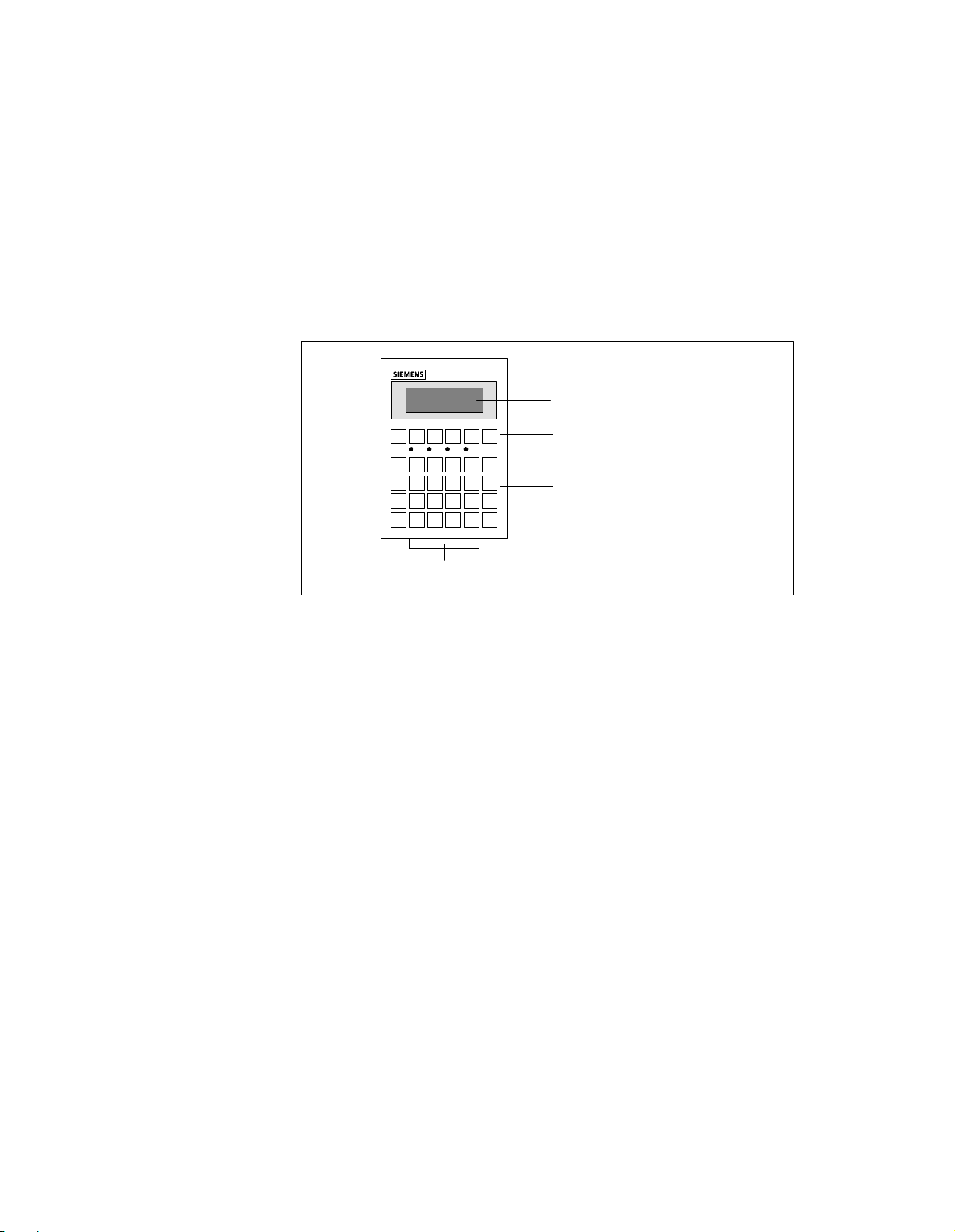
1.3 Design of Operator Panel OP5
OP5 versions
The OP5 is available in the following two versions:
OP5/A1 and
OP5/A2.
The two versions differ only in their communication options.
Figure 1-2 Design of Operator Panel OP5
LCD
Function keyboard
Soft keys
System keyboard
Interfaces
Display of up to 4 lines each having a maximum length of 20 characters; the
height of the characters is 5 mm.
6 keys (F1 to F6) for calling freely programmable, generally valid standard
functions.
4 keys (F2 to F5) may alternatively be configured as soft keys. Each of these
keys can be configured with different functions for the various screens.
24 keys with permanently assigned function calls.
The OP5/A1 has an interface for connecting the PLC/computer and printer.
The OP5/A2 has two interfaces for this purpose.
1-6
( ) J31069-D0840-U001-A2-7618
Manual OP5, OP15

1.4 Design of Operator Panel OP15
Product Description
OP15 versions
The OP15 is available in the following versions:
OP15/A1,
OP15/A2,
OP15/A1-VF,
OP15/A2-VF,
OP15/C1 and
OP15/C2.
The versions listed above differ in their display and communication options.
Figure 1-3 Design of Operator Panel OP15
Manual OP5, OP15
( ) J31069-D0840-U001-A2-7618
1-7

Product Description
LCD
Vacuumfluorescence
display
Function keyboard
Soft keys
OP15/A:
Display of 2 lines each containing up to 40 characters; the height of the characters is 5 mm.
OP15/C:
Display of up to 4 lines each having a maximum length of 20 characters; the
height of the characters is 8 mm;
or
display of up to 8 lines each having a maximum length of 40 characters; the
height of the characters is 4 mm.
OP15/A-VF:
Display of 2 lines each containing up to 40 characters; the height of the characters is 5 mm.
16 keys (K1 to K16), each having an LED for freely programmable functions. The LEDs can be driven from the PLC.
8 keys (F1 to F8) beneath the display, which can be configured with screenspecific functions.
System keyboard
Interfaces
24 keys with permanently assigned function calls.
3 interfaces for connecting the PLC and a printer or a computer.
1-8
( ) J31069-D0840-U001-A2-7618
Manual OP5, OP15

Functionality
Á
Á
Á
Á
Á
Á
Á
Á
Á
Á
Á
Á
Á
Á
Á
Á
Á
Á
Á
Á
Á
Á
Á
Á
Á
Á
Á
Á
Á
Á
Á
Á
Á
Á
Á
Á
Á
Á
Á
Á
Á
Á
Á
Á
Á
Á
Á
Á
Á
Á
Á
Á
Á
Á
Á
Á
Á
Á
Á
Á
Á
Á
Á
Á
Á
Á
Á
Á
Á
Á
Á
Á
2
Functions of OP5
and OP15 versions
Manual OP5, OP15
( ) J31069-D0840-U001-A2-7618
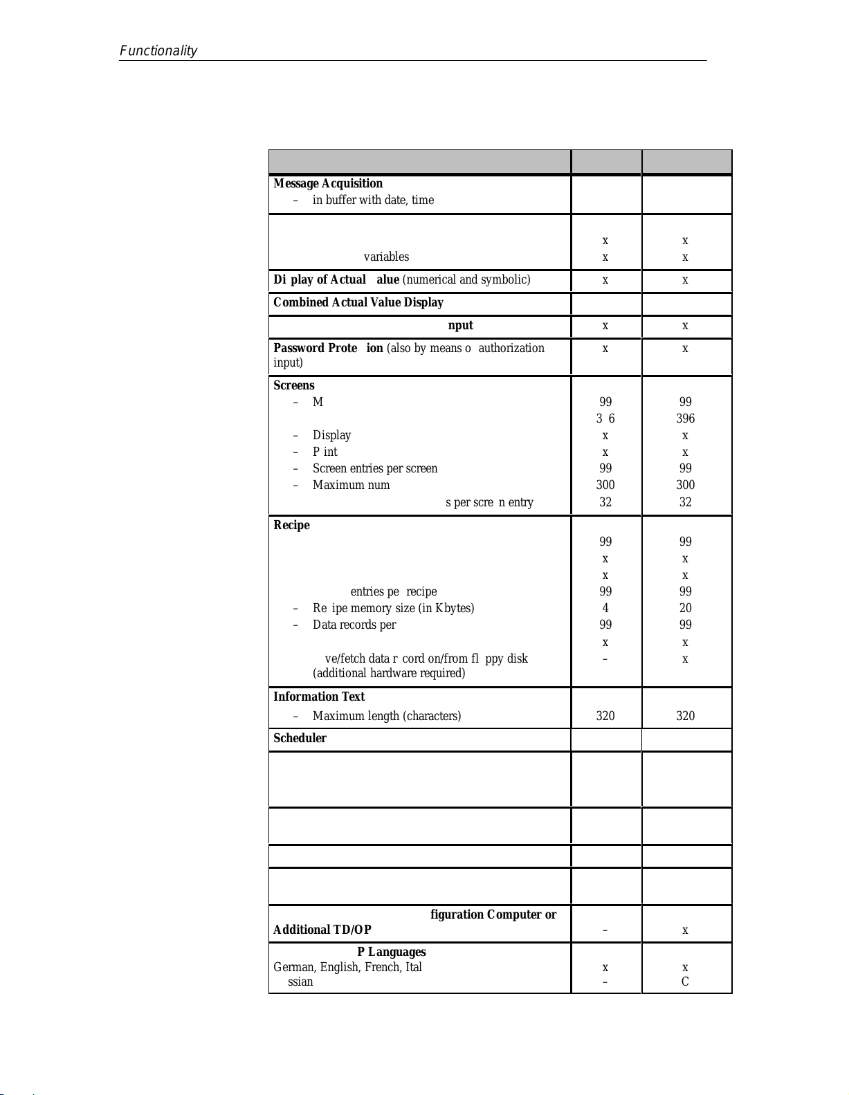
The table below provides an overview of the functions of Operator Panels
OP5 and OP15 with their different versions.
Table 2-1 Functionality of OP5 and OP15
Display
– Technology
БББББББББББББ
БББББББББББББ
БББББББББББББ
БББББББББББББ
– Lines x characters per line/character height (mm)
БББББББББББББ
БББББББББББББ
БББББББББББББ
БББББББББББББ
– Contrast control
Event Messages
БББББББББББББ
– Maximum number
– Maximum length (characters)
БББББББББББББ
– Display
БББББББББББББ
– Print
БББББББББББББ
– View event message text
БББББББББББББ
– Maximum number of entries in the event buffer
БББББББББББББ
– View event buffer
БББББББББББББ
– Print event buffer
БББББББББББББ
– Delete event buffer
Alarm Messages
БББББББББББББ
– Maximum number
БББББББББББББ
– Maximum length (characters)
– Display
БББББББББББББ
– Print
БББББББББББББ
– View alarm message text
БББББББББББББ
– Maximum number of entries in alarm buffer
БББББББББББББ
– View alarm buffer
БББББББББББББ
– Print alarm buffer
БББББББББББББ
– Delete alarm buffer
OP5 OP15
LCD
ÁÁÁ
ÁÁÁ
ÁÁÁ
ÁÁÁ
4x20/5
ÁÁÁ
ÁÁÁ
ÁÁÁ
ÁÁÁ
x
ÁÁÁ
499
80x
ÁÁÁ
x
ÁÁÁ
x
ÁÁÁ
x
ÁÁÁ
256
ÁÁÁ
x
ÁÁÁ
x
ÁÁÁ
x
ÁÁÁ
499
ÁÁÁ
80
x
ÁÁÁ
x
ÁÁÁ
x
ÁÁÁ
256
ÁÁÁ
x
ÁÁÁ
x
ÁÁÁ
x
A, C:
ÁÁÁ
LCD
ÁÁÁ
A-VF:
ÁÁÁ
VF
ÁÁÁ
A, A-VF :
2x40/5
ÁÁÁ
C:
ÁÁÁ
4x20/8 or
ÁÁÁ
8x40/4
ÁÁÁ
A, C
ÁÁÁ
999
80
ÁÁÁ
x
ÁÁÁ
x
ÁÁÁ
x
ÁÁÁ
256
ÁÁÁ
x
ÁÁÁ
x
ÁÁÁ
x
ÁÁÁ
999
ÁÁÁ
80
x
ÁÁÁ
x
ÁÁÁ
x
ÁÁÁ
256
ÁÁÁ
x
ÁÁÁ
x
ÁÁÁ
x
2-1
Á
Á
Á
Á
Á
Á
Á
Á
Á
Á
Á
Á
Á
Á
Á
Á
Á
Á
Á
Á
Á
Á
Á
Á
Á
Á
Á
Á
Á
Á
Á
Á
Á
Á
Á
Á
Á
Á
Á
Á
Á
Á
Á
Á
Á
Á
Á
Á
Á
Á
Á
Á
Á
Á
Á
Á
Á
Á
Á
Á
Á
Á
Á
Á
Á
Á
Á
Á
Á
Functionality
2-2
Table 2-1 Functionality of OP5 and OP15
OP15OP5
Message Acquisition
– in buffer with date, time, state
БББББББББББББ
Variable Input
БББББББББББББ
– Numbers or letters
БББББББББББББ
– Symbolic variables
Display of Actual Value (numerical and symbolic)
Combined Actual Value Display and Variable Input
Limit Value Check of Operator Input
Password Protection (also by means of authorization
БББББББББББББ
input)
Screens
БББББББББББББ
– Maximum number
– Maximum number of lines per screen
БББББББББББББ
– Display
БББББББББББББ
– Print
БББББББББББББ
– Screen entries per screen
БББББББББББББ
– Maximum number of fields per screen
– Maximum number of fields per screen entry
БББББББББББББ
Recipes
– Maximum number
БББББББББББББ
– View
БББББББББББББ
– Print
БББББББББББББ
– Recipe entries per recipe
– Recipe memory size (in Kbytes)
БББББББББББББ
– Data records per recipe (maximum)
БББББББББББББ
– Save/fetch data record in/from the OP
БББББББББББББ
– Save/fetch data record on/from floppy disk
(additional hardware required)
БББББББББББББ
Information Text
– Maximum length (characters)
БББББББББББББ
Scheduler times - 48
Function Keys
– Number
БББББББББББББ
– Integrated LEDs
БББББББББББББ
Soft Keys (number)
БББББББББББББ
Logs
Diagnostic Function
БББББББББББББ
(STATUS/FORCE VAR) S7/S5 only
Loop-Through Mode for Configuration Computer or
Additional TD/OP
БББББББББББББ
Configurable OP Languages
German, English, French, Italian, Spanish
БББББББББББББ
Russian
( ) J31069-D0840-U001-A2-7618
x
ÁÁÁ
ÁÁÁ
x
ÁÁÁ
x
x
x
x
x
ÁÁÁ
ÁÁÁ
99
396
ÁÁÁ
x
ÁÁÁ
x
ÁÁÁ
99
ÁÁÁ
300
32
ÁÁÁ
99
ÁÁÁ
x
ÁÁÁ
x
ÁÁÁ
99
4
ÁÁÁ
99
ÁÁÁ
x
ÁÁÁ
–
ÁÁÁ
320
ÁÁÁ
6
ÁÁÁ
–
ÁÁÁ
4 (of funct.
ÁÁÁ
keys)
x
x
ÁÁÁ
–
ÁÁÁ
x
ÁÁÁ
–
Manual OP5, OP15
ÁÁÁ
ÁÁÁ
ÁÁÁ
ÁÁÁ
ÁÁÁ
ÁÁÁ
ÁÁÁ
ÁÁÁ
ÁÁÁ
ÁÁÁ
ÁÁÁ
ÁÁÁ
ÁÁÁ
ÁÁÁ
ÁÁÁ
ÁÁÁ
ÁÁÁ
ÁÁÁ
ÁÁÁ
ÁÁÁ
8 (extra)
ÁÁÁ
ÁÁÁ
ÁÁÁ
ÁÁÁ
x
x
x
x
x
x
x
99
396
x
x
99
300
32
99
x
x
99
20
99
x
x
320
16
x
x
x
x
x
C

Table 2-1 Functionality of OP5 and OP15
Á
Á
Á
Á
Á
Á
Á
Á
Á
Á
Á
Á
Á
Á
Á
Á
Á
Á
Á
Á
Á
Á
Á
Á
Á
Á
Á
Á
Á
Á
Á
Á
Á
Á
Á
Á
Changing Languages in Online Mode
Communication by means of
SIMATIC S5
БББББББББББББ
– AS511
БББББББББББББ
–FAP
БББББББББББББ
– SINEC L2-DP
БББББББББББББ
БББББББББББББ
SIMATIC S7
БББББББББББББ
– PPI
– MPI
БББББББББББББ
БББББББББББББ
Other PLCs
БББББББББББББ
– SIMATIC 500/505
БББББББББББББ
– Free serial
БББББББББББББ
– Allen Bradley
БББББББББББББ
– Mitsubishi
3
ÁÁÁ
A1
ÁÁÁ
A1
ÁÁÁ
A2
ÁÁÁ
ÁÁÁ
ÁÁÁ
A2
A2
ÁÁÁ
ÁÁÁ
ÁÁÁ
x
ÁÁÁ
x
ÁÁÁ
1)
1)
ÁÁÁ
Functionality
OP15OP5
3
ÁÁÁ
A1, A1-VF, C1
ÁÁÁ
A1, A1-VF, C1
ÁÁÁ
A2, A2-VF, C2
ÁÁÁ
ÁÁÁ
ÁÁÁ
A2, A2-VF, C2
A2, A2-VF, C2
ÁÁÁ
ÁÁÁ
ÁÁÁ
x
ÁÁÁ
x
ÁÁÁ
1)
1)
ÁÁÁ
Manual OP5, OP15
( ) J31069-D0840-U001-A2-7618
1) Driver optional
2-3

Functionality
2-4
( ) J31069-D0840-U001-A2-7618
Manual OP5, OP15

Part II Basic functions
Using the OP with Its Standard
Functions
General Operation
3
4
Screens
Password Protection
Message Handling
Recipes
STATUS VAR and FORCE VAR
Functions with the OPs
System Settings on Standard
Screens
5
6
7
8
9
10

-2
( ) J31069-D0840-U001-A2-7618
Manual OP5, OP15

Using the OP with Its Standard Functions
3
Loading a
configuration
Using standard
screens
Once the operating voltage has been connected, you have to load a configuration into the OP so that you can operate it. The OP is in Transfer mode until a
configuration is loaded.
The configuration software supplied to you, ProT ool/Lite, includes a configuration which contains standard screens. You can choose all the functions required for operating the OPs by using these standard screens. The different
functions are described in this manual with reference to the standard screens.
3.1 Operating Levels
Message level and
screen level
In OP operation, you have to distinguish between two distinct operating levels, between which you can switch:
Message level
At the message level, current messages are displayed.
Screen level
At the screen level, functions are chosen, serviced and executed.
The message level is the highest level on the OP. At message level, waiting
event messages, alarm messages and system messages are displayed. After
the OP starts up, it changes to message level and displays the ”standby message”.
The screen level is reached by pressing the ENTER key. The first screen to
be called is the ”start” screen. From the start screen you branch, depending
on the configuration, to other screens. On the screens, you view current process values, can enter values and initiate functions by means of soft keys.
Screen hierarchy
Manual OP5, OP15
( ) J31069-D0840-U001-A2-7618
The linking of individual screens is referred to as a ”screen hierarchy”. If you
go to the bottom of the screen hierarchy, you go back one stage by pressing
key ESC, right back to the start screen should you wish. From here you can
return to the message level by pressing the ESC key. You can also return directly to the message level from a screen, depending on the configuration.
3-1
Using the OP with Its Standard Functions
Changing operating levels
Forced change to
message level
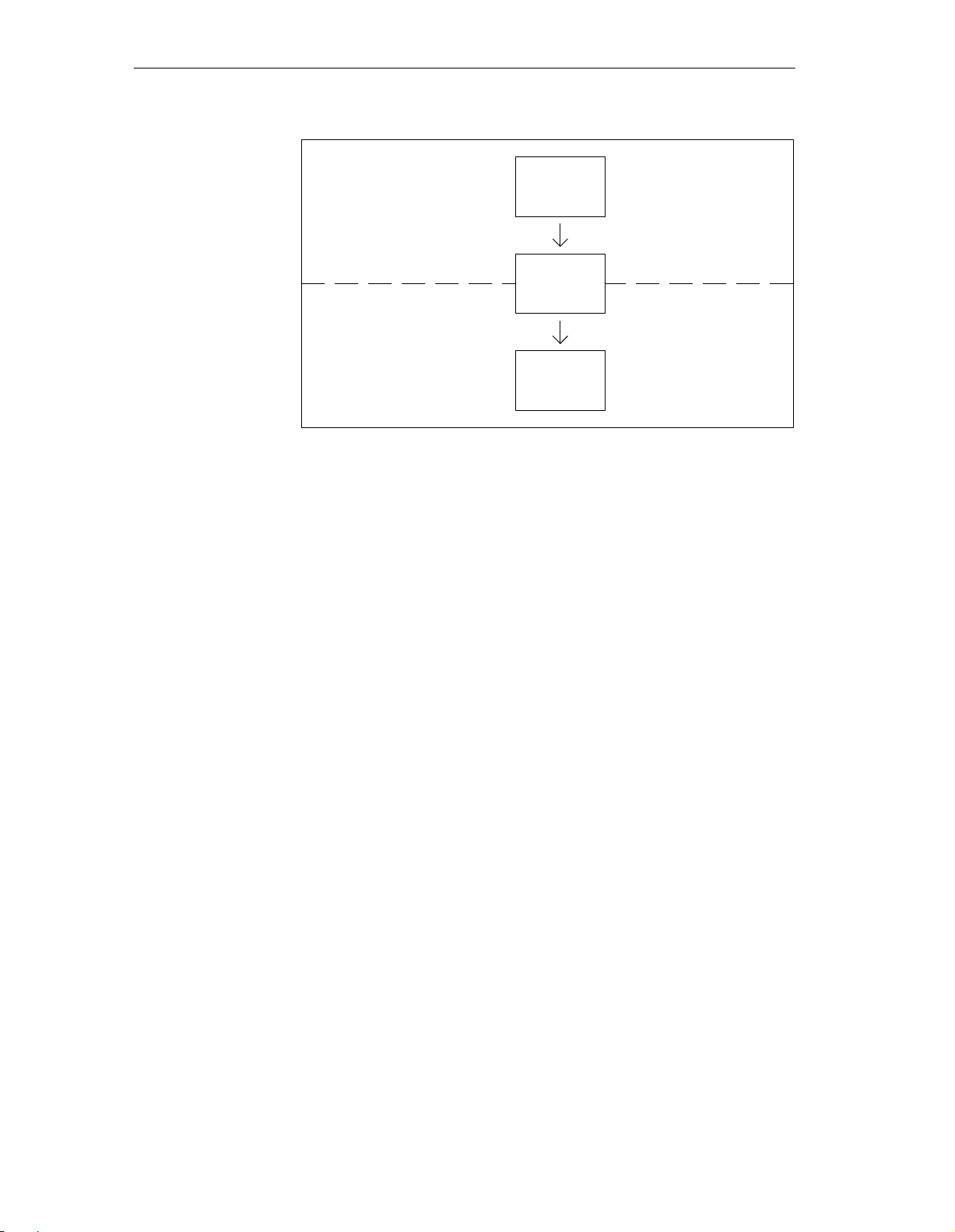
You change the operating level
from message level to screen level by pressing the ENTER key,
from screen level to message level by pressing the ESCAPE key.
Figure 3-1 illustrates how you can change from one operating level to another.
You cannot branch backward from the message level by pressing ESCAPE. The
key is designed to terminate the display of a system message at this level.
ENTER
⇓
Figure 3-1 Changing between Message Level and Screen Level
You exit from the screen level automatically whenever a system message or
an alarm message is waiting to be displayed. The OP then changes to message level to display the message. You cannot exit from the message level
while a system message or unacknowledged alarm message is being displayed. The display of an unacknowledged alarm message is indicated on the
OP by the
⇑
3-2
– alarm message flashing and
– lit ACK LED.
You acknowledge an alarm message by pressing the ACK key. You hide a
system message by pressing the ESCAPE key.
Once the alarm message has been acknowledged or the system message
cleared, the OP returns to the point from which it changed to the message
level.
( ) J31069-D0840-U001-A2-7618
Manual OP5, OP15

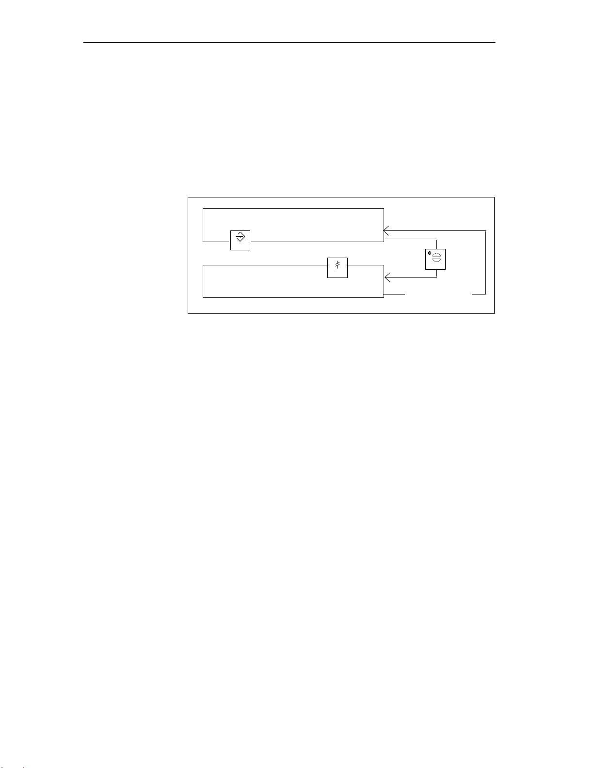
3.2 Standard Screens
Using the OP with Its Standard Functions
Basic operations
with standard
screens
Functions on
standard screens
The standard screens contain functions that are fundamental to OP operation.
They include, for instance, calling and printing message buffers, editing passwords and modifying parameters in online mode. Process-specific implementations, such as event messages or screens for the process, are not included.
Standard screens are called from a basic screen by means of a soft key. From
the basic screen, a jump is made to the following screens:
Alarm messages
At this point the alarm buffer is called, printed or deleted.
Event messages
At this point the event buffer is called, printed or deleted.
Screens
At this point the screen directory is called to edit or print screens. All the
screens which were given the ”directory” attribute are listed here. If you
still have not created any screens of your own, the directory will be
empty .
Data records
At this point you can set up and edit data records. You can also transfer
data records from the OP to the PLC and back.
System settings
At this point you can modify settings in online mode. This includes, for
example, printer parameters, interface parameters, mode, and language
changing.
Status variable
Force variable
Edit password
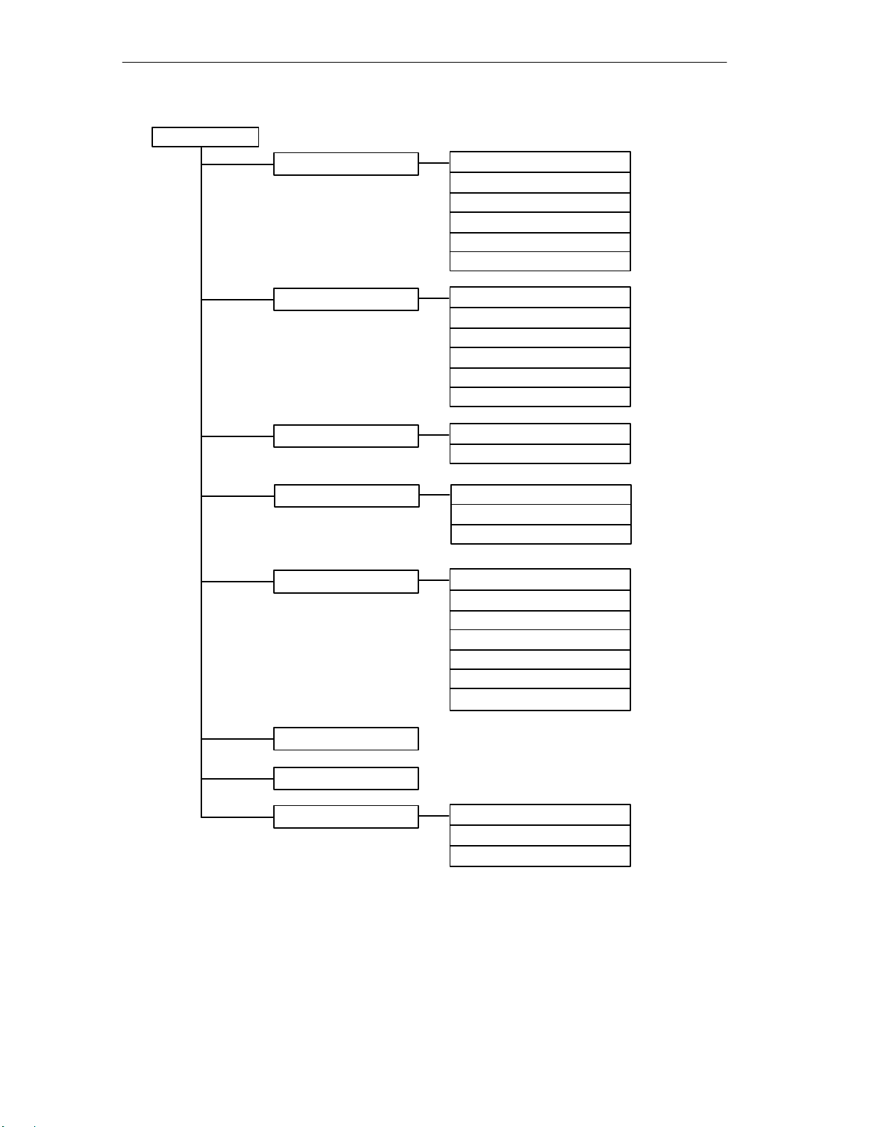
Figure 3-2 shows an overview of the screen hierarchy of standard screens.
You will find detailed information on functions and handling standard screens
in the relevant chapters of this manual.
Manual OP5, OP15
( ) J31069-D0840-U001-A2-7618
At this point the PU function STATUS VAR is called; you can use it to
display PLC operands.
At this point the PU function FORCE VAR is called; you can use it to
display and modify PLC operands.
At this point the superuser assigns passwords for the different password
levels. Furthermore, login and logout are included here.
3-3
Using the OP with Its Standard Functions
Basic Screen
Event Messages
Alarm Messages
Screens
Data Records
View
Print
Number
Delete
Overflow
Text
View
Print
Number
Delete
Overflow
Text
Edit
Print
Edit
Change
Print
System Settings
Status Variable
Force Variable
Edit Password
Figure 3-2 The Standard Screens
Operating mode
Display message
System messages
Change language
Date/Time
Printer parameters
IF1/IF2 ( )
Login
Logout
Edit
3-4
( ) J31069-D0840-U001-A2-7618
Manual OP5, OP15
 Loading...