

Siemens OH110, OP110, HI110, HI112 Technical Manual
Building Technologies
Automatic fire detectors
OH110, OP110, HI110, HI112
Technica l Manual
A6V10316298_e_en_-2014-05-21 Control Products and Systems

Legal notice
Legal notice
Technical specifications and availability subject to change without notice.
© 2012-2014 Copyright by Siemens Switzerland Ltd
Transmitt al, reproduction, dissemination and/or editing of this doc ument as well as
utilization of its contents and communication thereof to others without expr ess
authorization are prohibited. Offenders will be held liable for payment of damages.
All rights creat ed by patent grant or registration of a utility model or design patent
are reserved.
Issued by:
Siemens Switzerland Ltd.
Infrastructure & Cities Sector
Building Technologies Div ision
International Headquarters
Gubelstrasse 22
CH-6301 Zug
Tel. +41 41 724-2424
www.siemens.com/buildingtechnologies
Edition: 2014-05-21
Document ID: A6V10316298_e_en_--
2
Building Technologies A6V10316298_e_en_--
Fire Safety 2014-05-21

Table of contents
1 About this document ......................................................................................5
1.1 Applica ble docu ments .......................................................................................7
1.2 Download center...............................................................................................7
1.3 Technica l terms ................................................................................................7
1.4 History of changes ............................................................................................8
2 Safety ..............................................................................................................9
2.1 Safety instru ct ions ............................................................................................9
2.2 Safety regu lat ions for the meth od of operat ion ................................................ 11
2.3 Standa rds an d directives co mp lied with .......................................................... 13
2.4 Releas e Notes ................................................................................................ 13
3 Structur e and function ................................................................................. 14
3.1 Overview ........................................................................................................ 14
3.1.1 Details for ordering ........................................................................... 14
3.1.2 Product version ES .......................................................................... 15
3.2 Point dete ctor ................................................................................................. 16
3.2.1 Multi-s ensor fire detecto r .................................................................. 16
3.2.2 Smoke detecto r................................................................................ 17
3.2.3 Heat detecto r ................................................................................... 18
3.3 Function ......................................................................................................... 19
3.3.1 Parame ter sets ................................................................................ 19
3.3.2 Diagnosis levels ............................................................................... 19
3.3.3 Interna l alarm indicator ..................................................................... 20
3.3.4 Conne ction for external alar m indicators ........................................... 21
3.3.5 Test mode ....................................................................................... 21
3.4 Mechanical setup ............................................................................................ 22
3.5 Accessories .................................................................................................... 23
3.5.1 Detecto r base (collective) DB110 ..................................................... 23
3.5.2 Detecto r base (collective) DB110D ................................................... 23
3.5.3 Detecto r base (collective) DB110R ................................................... 24
3.5.4 Detecto r base (collective) DB110 RD ................................................ 24
3.5.5 Design ation plate FDBZ29 1 ............................................................. 25
3.5.6 Detecto r base seal RS720 ............................................................... 25
3.5.7 Base attachmen t BA720 .................................................................. 25
3.5.8 Base attachment wet BA721 ............................................................ 26
3.5.9 Design ation plate DBZ119 3A ........................................................... 26
3.5.10 Detecto r heating unit FDBH291 ........................................................ 26
3.5.11 Protect ive cage DBZ11 94 ................................................................ 27
3.5.12 EMC-pro tective cage FDBZ29 4 ........................................................ 27
3.5.13 Detecto r locking device LP720 ......................................................... 27
3.5.14 Micro termina l DBZ1 190-AA ............................................................. 28
3.5.15 Conne ction terminal DBZ1190-A B.................................................... 28
Building Technologies A6V10316298_e_en_-Fire Safety 2014-05-21
3

4 Planning ........................................................................................................ 29
4.1 Compatibility ................................................................................................... 29
4.2 Multi-s ens or fire detecto r ................................................................................ 29
4.2.1 Parame ter sets ................................................................................ 2 9
4.2.2 Specifica tions .................................................................................. 30
4.3 Smoke detector .............................................................................................. 3 1
4.3.1 Parame ter sets ................................................................................ 3 1
4.3.2 Specifica tions .................................................................................. 31
4.4 Heat detector .................................................................................................. 32
4.4.1 Parame ter sets ................................................................................ 3 2
4.4.2 Specifica tions .................................................................................. 33
5 Mount ing / Installatio n .................................................................................. 34
5.1 Required space .............................................................................................. 3 4
5.2 Detecto r base (collec t ive) D B1 1 0 / DB11 0 x / DB11 0 xx .................................... 35
5.3 Detecto r base seal RS720 .............................................................................. 36
5.4 Base attachment BA720 ................................................................................. 37
5.5 Base attachment wet BA721 ........................................................................... 39
5.6 Detecto r locking device LP72 0 ........................................................................ 41
5.7 Design ation plate FDBZ291 ............................................................................ 42
5.8 Cable entry ..................................................................................................... 4 3
5.8.1 Auxiliar y terminals DBZ11 90-A A/-AB ............................................... 43
5.9 Detecto r dus t cap ........................................................................................... 4 4
5.10 Detecto r heating unit FDBH291 ...................................................................... 45
5.10.1 Installat ion of the detecto r heat ing unit ............................................. 45
5.10.2 Conne ction of the detector hea ting unit ............................................ 46
5.11 Protect ive cages ............................................................................................. 47
5.11.1 Installat ion of the protect i ve cages ................................................... 47
5.11.2 Ground ing of the EMC-pro tecti ve cage FDBZ294 ............................. 47
5.12 Conne ction diagram ....................................................................................... 48
6 Commissioning............................................................................................. 49
7 Mainte nance / Repair .................................................................................... 5 0
7.1 Performance check ......................................................................................... 50
7.2 Testing the point detec tor ............................................................................... 50
8 Specifications ............................................................................................... 51
8.1 Technica l data for multi-sens or fire detector OH110 ........................................ 51
8.2 Technica l data for s moke de tec tor OP1 10 ...................................................... 52
8.3 Technica l data for heat detectors HI11 0 / HI112 .............................................. 54
8.4 Dimens ions .................................................................................................... 5 6
8.5 Environ mental compatib ility and dispo sal ........................................................ 56
Index ............................................................................................................. 5 7
4
Building Technologies A6V10316298_e_en_--
Fire Safety 2014-05-21

Applicable documents
1 About this document
Goal and purpose
This document contains information on automat ic fire detectors. Following the
instructions consistently will ensur e that the product can be used safely and without
any problems.
Scope
The document is valid f or the following automatic f ire detectors:
l OH110
l OP110
l HI110
l HI112
Target groups
The information in this document is intended f or the following target groups:
Target group Activity Qualificat ion
About this document
1
Product Manager
Project Manager
Project engineer
Installation personnel
Maintenance personnel l Carries out all maintenance work.
l Is responsible for information passing
between the manufacturer and regional
company.
l Coordinates the flow of information
between the individual groups of people
involved in a project.
l Coordinates the deployment of all
persons and resources involved in the
project according to schedule .
l Provides the information required to run
the project.
l Sets parameters for product depending
on specific national and/or customer
requirements.
l Checks operability and approves the
product for commissioning at the place
of installation.
l Is responsible for trouble-shooting.
l Assembles and installs the product
components at the place of installation.
l Carries out a performance check
following installation.
l Checks that the products are in perfect
working order.
l Searches for and corrects malfunctions.
l Has obtained suitable specialist training
for the function and for the products.
l Has attended the training courses for
Product Managers.
l Has obtained suitable specialist training
for the function and for the products.
l Has attended the training courses for
Project Managers.
l Has obtained suitable specialist training
for the function and for the products.
l Has attended the training courses for
Product Engineer.
l Has received specialist training in the
area of building installation technology
or electrical installations.
l Has obtained suitable specialist training
for the function and for the products.
Building Technologies A6V10316298_e_en_-Fire Safety 2014-05-21
5

About this document
Applicable documents
The 'i' symbol identif ies supplementary information and tips for an easier way of
1
Reference document and source language
l The source language of this document is German (de).
l T he reference version of this document is the international version in English.
The international ver sion is not localized.
The reference document has the following designation:
ID_x_en_-x = version, en = English, -- = international
Document identification
The document ID is structured as follows:
ID code Examples
ID_ModificationIndex_Language_COUNTRY
-- = multilingual or international
A6V10215123_a_de_DE
A6V10215123_a_en_-A6V10315123_a_--_--
Date format
The date format in the document corresponds to the recomm endation of
international standard ISO 8601 (format YYYY-MM-DD).
Conventions for text marking
Markups
Special markups are shown in this document as follows:
⊳ Requirement for a behavior instruction
1.
2.
– Version, option, or detailed information for a behavior instruction
⇨ Intermediate result of a behavior instruction
⇨ End result of a behavior instruction
Behavior instruction with at least two operation sequences
l Numbered lists and behavior instructions with an operation
sequence
[➙ X] Reference to a page number
'Text' Quotation, reproduced identically
<Key> Identificat ion of keys
Supplementary information and tips
working.
6
Building Technologies A6V10316298_e_en_--
Fire Safety 2014-05-21

Applicable documents
1.1 Applicable documents
You will also
find information about search variants and links t o mobile
Document ID Name
008331 List of compatibility (for 'Sinteso™' product line)
A6V10201731
A6V10301051
A6V10316300
A6V10406006
Installation Detector exchanger DX791, adapter for detector
exchanger FDUD491
Data sheet Automatic fire detectors OH110, OP110, HI110,
HI112
Installation Detector base (collective) DB110, DB110D,
DB110R, DB110RD, detector base seal RS720, detector
locking device LP720, base attachment BA720
Installation Base attachment wet BA721, Detector designation
plate DBZ1193A, Protective cage DBZ1194, EMC-protective
cage FDBZ294
Please also observe the documentation for your fire detection system.
1.2 Download center
You can download various types of documents, such as data sheets, installation
instructions, and license texts v ia the following Internet address:
http://siemens.com/bt/download
About this document
1
l Ent er the document ID in the 'Find by keywords' input box.
applications (apps) for various systems on the home page.
1.3 Technical terms
Term Explanation
AI Alarm indic a tor
ES Product version
Building Technologies A6V10316298_e_en_-Fire Safety 2014-05-21
7

About this document
History of changes
The first edition of a language version or a country variant may, for example, be
1
1.4 History of changes
The reference docum ent's version applies to all languages into which the reference
document is trans lated.
version 'd' inst ead of 'a' if the reference document is already this version.
The table below shows this document's history of changes:
Modification index Edition date Brief description
e 2014-05-21 Editorial revision
d 2014-02-10
c 2013-08-31
b 2012-06-15
a 2012-04 First edition
Data sheet in 'Applicable documents' chapter added; base
attachment wet BA721, designation plate DBZ1193A, protective cage
DBZ1194, EMC-protective cage FDBZ294, and detector heating unit
FDBH291 added; 'Download center' chapter added
Information on LPCB approvals for OH110, HI110, and HI112 point
detectors
CPD/G number for OH110/OP110 added, new date format in line with
ISO 8601 (yyyy-mm-dd)
The table below shows the published language versions with the corresponding
modification index:
Modification index en_-- de_-- fr_-- it_-- es_--
e x x x x x
d x x x x x
c X X X X X
b X X X X X
a X X X X X
X = published
– = no publication with this modification index
8
Building Technologies A6V10316298_e_en_--
Fire Safety 2014-05-21
Safety instructions
2 Safety
Signal word
Danger level
2.1 Safety instructions
The safety notices mus t be observed in order to protect people and property.
The safety notices in this document contain the following elements:
l Symbol for danger
l Signal word
l Nature and origin of the danger
l Consequences if the danger occurs
l Measures or prohibit ions for danger avoidance
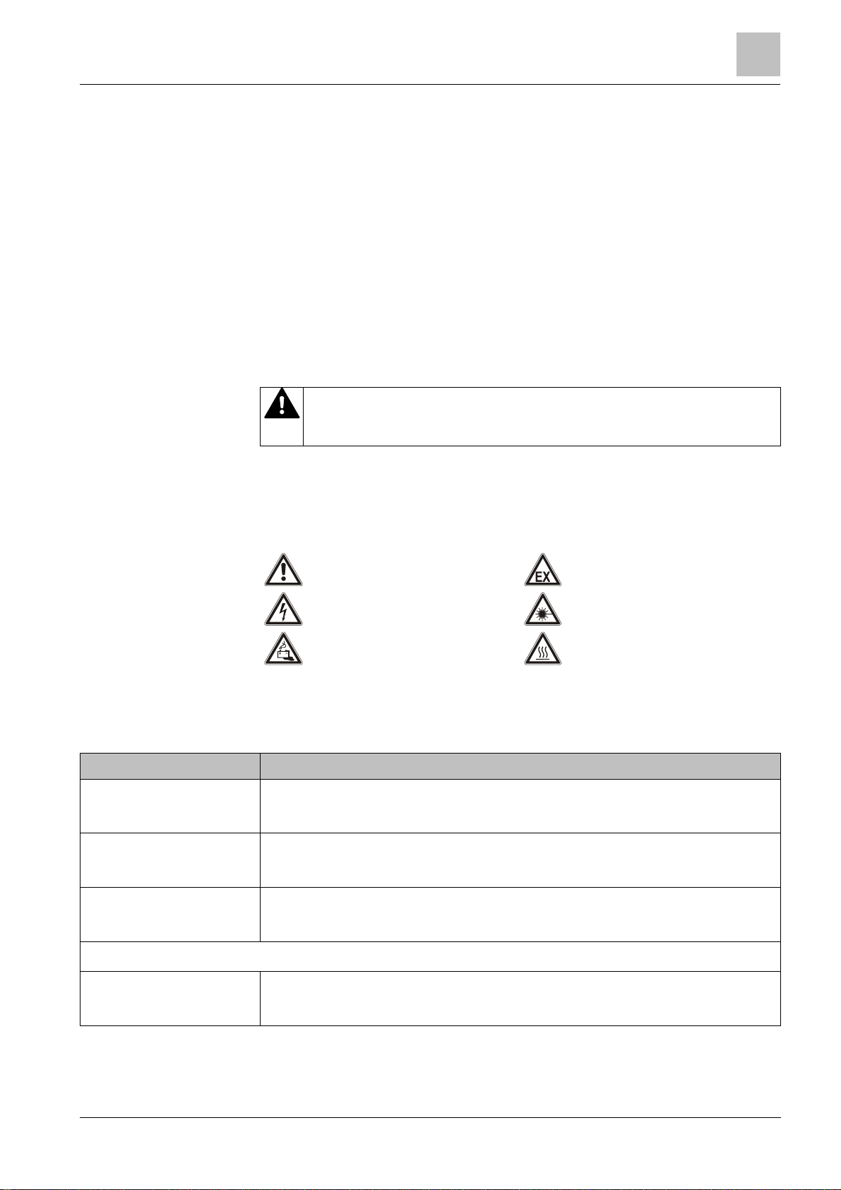
Symbol for danger
This is the symbol for danger. It warns of risks of injury.
Follow all measures ident ified by this symbol to avoid injury or deat h.
Safety
2
Additional dan ger symbols
These symbols indic ate general dangers, the type of danger or poss ible
consequences, measures and prohibitions, examples of which are shown in the
following table:
General danger Explosive atmosphere
Voltage/electric shock Laser light
Battery Heat
Signal word
The signal word classifies the danger as defined in the following table:
DANGER DANGER identifies a dangerous situation, which will result directly in death or
serious injury if you do not avoid this situation.
WARNING WARNING identifies a dangerous situation, which may result in death or serious
injury if you do not avoid this situation.
CAUTION CAUTION identifies a dangerous situation, which could result in slight to
NOTICE NOTICE
Building Technologies A6V10316298_e_en_-Fire Safety 2014-05-21
moderately serious injury if you do not avoid this situation.
identifies possible damage to property that may result from non-
observance.
9

2
Safety instructions
Nature and origin of the danger
●
Measures / prohibit ions for danger avoidance
Nature and origin of the danger
●
Measures / prohibit ions for danger avoidance
Safety
How risk of injury is presented
Information about the risk of injury is shown as follows:
WARNING
Consequences if the danger oc curs
How possible damage to property is presented
Information about possible damage to property is s hown as follows:
NOTICE
Consequences if the danger oc curs
10
Building Technologies A6V10316298_e_en_--
Fire Safety 2014-05-21

Safety
Safety regulations for the method of operation
Electrical volt age
regulations.
2.2 Safety regulations for the method of operation
National standards, regulations and legislation
Siemens products ar e developed and produced in compliance with the relevant
European and international safety standards . Should additional national or local
safety standards or legislation concerning the planning, assembly, installation,
operation or disposal of the product apply at the place of operation, then these
must also be taken into account together with the safety regulations in the product
documentation.
Electrical installations
WARNING
Electric shock
● Work on electrical installations may only be carried out by qualified
electricians or by instructed persons work ing under the guidance and
supervision of a qualified electrician, in accordanc e with the electrotechnical
2
l W herever possible disconnect products from the power supply when carrying
out commissioning, maintenance or repair work on them.
l Lock volt-free areas to prevent them being switched back on again by mistake.
l Label the connection terminals with external external voltage using a
'DANGER External voltage' sign.
l Rout e mains connections to products separately and fuse them with their own,
clearly marked fuse.
l F it an easily accessible disconnecting device in accordance with IEC 60950-1
outside the installation.
l Produce earthing as stated in local safet y regulat ions.
Assembly, installation, commissioning and maintenance
l If you require tools such as a ladder, these must be safe and must be intended
for the work in hand.
l W hen starting the fire control panel ensure that unstable conditions cannot
arise.
l Ensure that all points listed in the 'Testing the product operability' section below
are observed.
l You may only set controls to normal function when the product operability has
been completely tested and the system has been handed over to the customer.
Building Technologies A6V10316298_e_en_-Fire Safety 2014-05-21
11

2
Safety regulations for the method of operation
Safety
Testing the product operability
l Prevent the remot e transmis sion from trigger ing err oneously.
l I f testing building installations or activating devices from third-party companies,
you must collaborate with the people appointed.
l T he activation of fire control installations for test purposes must not cause
injury to anyone or damage to the building installations. The following
instructions m ust be observed:
– Use the correct potential for activation; this is generally the potential of the
building installation.
– Only check controls up to the interface (relay with blocking opt ion).
– Make sure that only the controls to be tested are activated.
l I nform people before testing the alarm devices and allow for possible panic
responses.
l I nform people about any noise or mist which may be produced.
l Bef ore testing the remote transmission, inform the corresponding alarm and
fault signal receiving stations.
Modifications to the system design and the products
Modifications to the system and to individual products m ay lead to faults,
malfunctioning and safety risks. Written confirmation must be obtained from
Siemens and the corresponding safety bodies for m odifications or additions.
Modules and spare parts
l Components and spare parts must comply with the technical specifications
defined by Siemens. Only use products specified or recommended by
Siemens.
l Only use fuses with t he specified fuse characteristics.
l Wrong battery types and improper battery changing lead to a risk of explosion.
Only use the same battery type or an equivalent battery t ype recommended by
Siemens.
l Bat teries must be disposed of in an environmentally friendly manner. Observe
national guidelines and regulations.
Disregard of the safety regulations
Before they ar e delivered, Siemens products ar e tested to ensure they function
correctly when used properly. Siemens disclaims all liability for damage or injuries
caused by the incorrec t application of the instructions or the disregard of danger
warnings contained in the documentation. This applies in particular to the following
damage:
l Per sonal injuries or damage to property caused by improper use and incorrect
application
l Per sonal injuries or damage to property caused by disregarding safety
instructions in the documentation or on the product
l Personal injury or damage to property caused by poor maintenance or lack of
maintenance
12
Building Technologies A6V10316298_e_en_--
Fire Safety 2014-05-21

Standards and directives c
omplied with
2.3 Standards and directives complied with
Limited or non
-
existent fire detection
detection installation.
Incorrect planning and/or configurat ion
detection installation.
A list of the standards and directives complied wit h is available from your Siemens
contact.
2.4 Release Notes
Limitations t o the configuration or use of devices in a fire detection installation with
a particular firmware version are possible.
WARNING
Personal injury and damage to property in the event of a fire.
● Read the 'Release Notes' before you plan and/or configure a fire detection
installation.
● Read the 'Release Notes' before you carry out a firmware update to a fire
Safety
2
NOTICE
Important st andards and specifications are not satisfied.
Fire detection installation is not accepted f or commissioning.
Additional expense result ing from necessary new planning and/ or configuration.
● Read the 'Release Notes' before you plan and/or configure a fire detection
installation.
● Read the 'Release Notes' before you carry out a firmware update to a fire
Building Technologies A6V10316298_e_en_-Fire Safety 2014-05-21
13
Structure and function
Overview
3
3 Structure and functio n
3.1 Overview
In this document t he following point detectors are r eferred to collectively using the
term 'Automatic fire detectors':
l Multi-sensor fire detector (collective) OH110
l Smoke detector (collective) OP110
l Heat detector (collective, differential) HI110
l Heat detector (collective, static) HI112
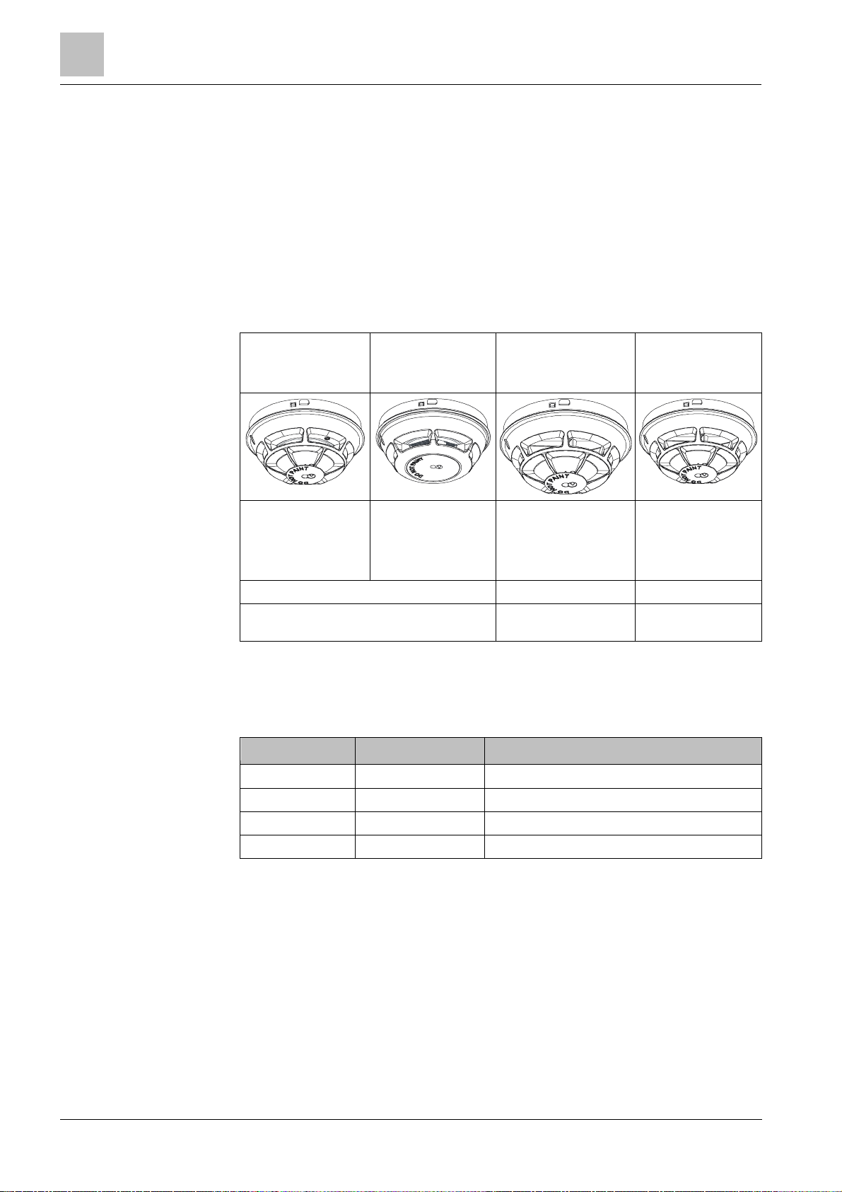
Multi- se nsor fire
detector
OH110
Can be used on
conventional detector
lines and collective
detector lines
2 parameter sets 1 parameter set 2 parameter sets
Detection behavior can be selected
Smoke detector
Can be used on
conventional
detector lines and
collective detector
lines
3.1.1 Details for ord ering
Type Order no. Designation
OP110
Heat detector
(collective, differential)
HI110
Can be used on
conventional detector
lines and collective
detector lines
Detection behavior
cannot be selected
Heat detector
(collective, static)
HI112
Can be used on
conventional
detector lines and
collective detector
lines.
Detection behavior
can be selected
OH110 S54372-F11-A1 Multi-sensor fire detector (collective)
OP110 S54372-F4-A1 Smoke detector (collective)
HI110 S54372-F9-A1 Heat detector (collective, dif ferential)
HI112 S54372-F10-A1 Heat detector (collective , static)
14
Building Technologies A6V10316298_e_en_--
Fire Safety 2014-05-21
Overview
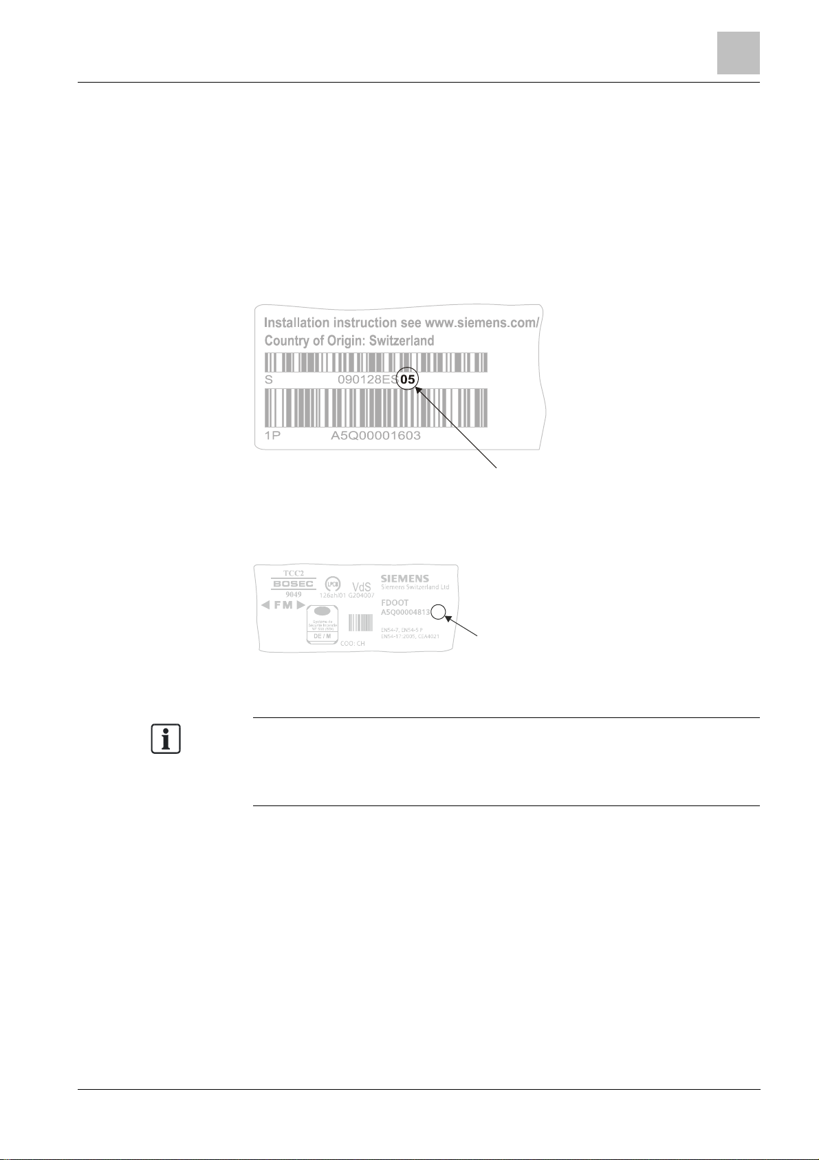
3.1.2 Product version ES
ES
Depending o
n the product and var ious approvals, the product labels may differ in
The product version ES provides the technical stat us of a device in t erms of
software and hardware. The product version is provided as a two-digit number.
You will find the det ails of your device's product ver sion:
l On the packaging label
l On the product label or the type plate
Product version on the packaging label
Details of the product version can be found directly on the pac kaging label in the
barcode:
Structure and function
3
Example of a packaging label with details of the product version
Product version on the product label and t he type plate
Details of the product version can be found after the device order number:
04
ES
Example of a product label with details of the product version
terms of the informat ion type and layout.
Look for your device' s order number on the product label.
You will find the produc t version after the order number.
Building Technologies A6V10316298_e_en_-Fire Safety 2014-05-21
15
Structure and function
Point detector
4
3
3.2 Point detector
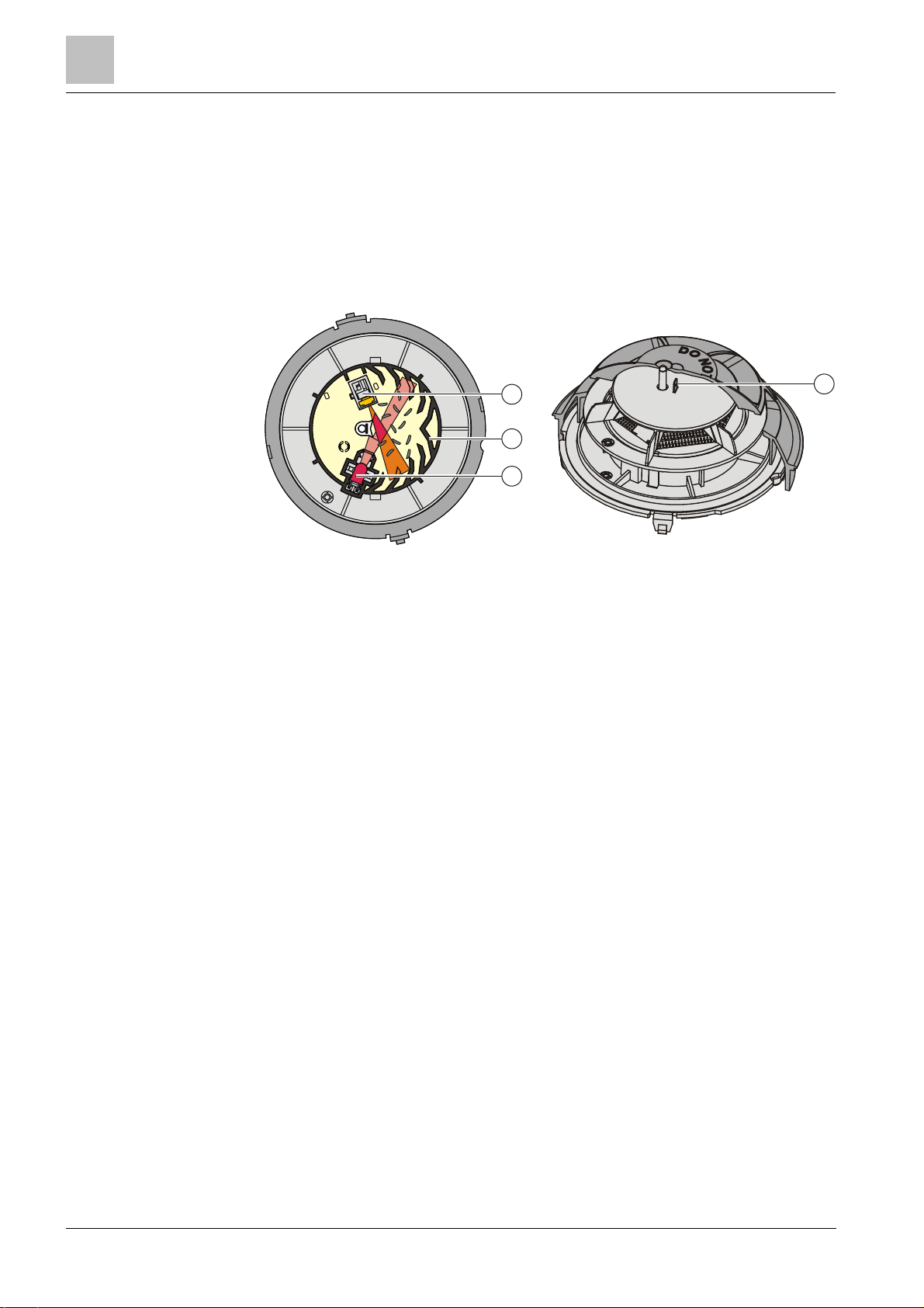
3.2.1 Multi-sensor fire detector
The multi-sensor fire detector OH110 is a multiple-criteria fire detect or with one
optical and one thermal sensor.
Structure and function
3
1
2
1 Labyrinth 3 Optical receiver
2 Optical transmitter 4 Heat sensor
The point detect or has a high-quality opto-electronic measuring chamber. The
measuring chamber contains:
l One optical transmitter
l One optical receiver
l One thermal sensor
The transmitter lights up the smoke particles. The scattered light then hits the
receiver (photodiode) and generates a measurable electric signal.
In addition, t he heat sensor makes it possible to detect fires in cases where no
smoke has been generated.
The combination of optical and thermal sensor signals optim izes detection
reliability with the following benefits.
l Early detection of all types of fire, whether they generate light or dark smoke, or
no smoke at all.
l The fire detector can be operated at a lower sensitivity level, thus achieving
improved immunity against false alarms which may be caused by c old
aerosols. In t he event of an open fire, the smoke sensitivity level is r aised by an
increase in temperature which makes rapidly burning f ires easier to detect.
The multi-sensor fire detector OH110 has two parameter sets: 'Robust' and
'Sensitive'.
16
Building Technologies A6V10316298_e_en_--
Fire Safety 2014-05-21
See also
2 Mult i-sensor fire detector [➙ 29]
Point detector
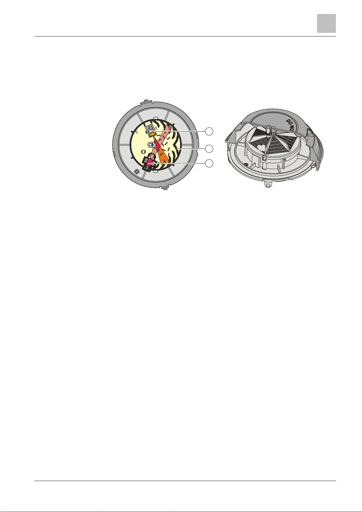
3.2.2 Smoke detector
The wide-spectrum smoke detector OP110 is an optical smoke det ector with one
optical sensor.
Structure and function
Structure and function
3
1
2
3
Labyrinth 3 Optical receiver
1
2
Optical transmitter
The wide-spectrum smoke detector has the same measuring cham ber as the multisensor fire detector.
The point detector has two parameter sets: 'Standard' and 'Sensitive'.
See also
2 Smoke detector [➙ 31]
17
Building Technologies A6V10316298_e_en_-Fire Safety 2014-05-21
Structure and function
Point detector
1
3
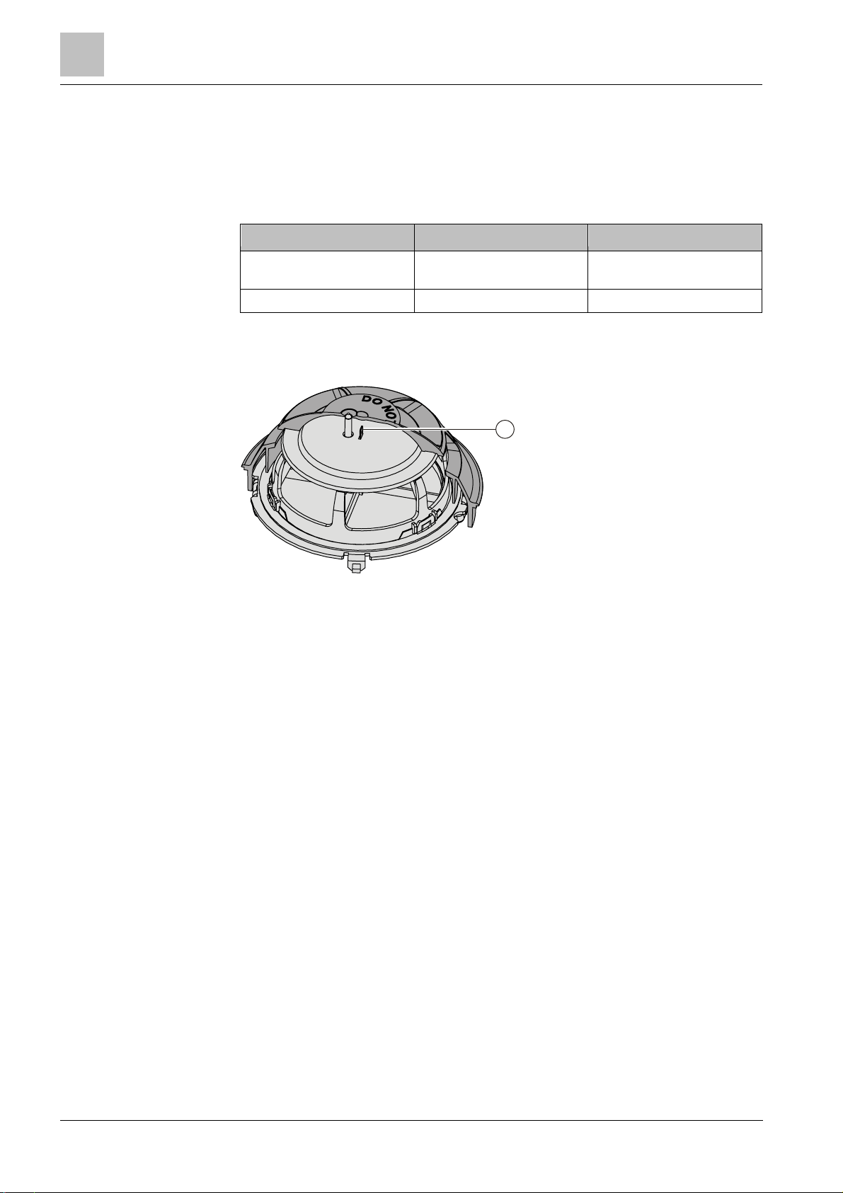
3.2.3 Heat detector
The heat detectors HI110 and HI112 are pure heat detectors with one thermal
sensor.
The following table indicates the most important differences between the two heat
detectors.
Parameter HI110 HI112
Alarm activation by: l Temperature increase
Number of parameter sets 1 2
l Reaching the maximum
temperature
Structure and function
1 Heat sensor
The heat detect or HI110 has one parameter set: 'A1R' (differential).
The heat detector HI112 has two parameter sets 'A2S' (static) and 'B'.
See also
2 Heat detector [➙ 32]
18
Building Technologies A6V10316298_e_en_--
Fire Safety 2014-05-21
 Loading...