

Siemens OOH740-A9-Ex Technical Manual
Building Technologies
OOH740-A9-Ex
Automatic fire detector
Technica l Manual
A6V10367521_h_en_-2015-02-02 Control Products and Systems

Legal notice
Legal notice
Technical specifications and availability subject to change without notice.
© Siemens Switzerland Lt d, 2012
Transmitt al, reproduction, dissemination and/or editing of this doc ument as well as
utilization of its contents and communication thereof to others without expr ess
authorization are prohibited. Offenders will be held liable for payment of damages.
All rights creat ed by patent grant or registration of a utility model or design patent
are reserved.
Issued by:
Siemens Switzerland Ltd.
Building Technologies Div ision
International Headquarters
Gubelstrasse 22
CH-6301 Zug
Tel. +41 41 724-2424
www.siemens.com/buildingtechnologies
Edition: 2015-02-02
Document ID: A6V10367521_h_en_--
2
Building Technologies A6V10367521_h_en_--
Fire Safety 2015-02-02

Table of contents
1 About this document ......................................................................................7
1.1 Applicable documents ..................................................................................... 11
1.2 Downloa d center............................................................................................. 11
1.3 Technica l terms, abbreviation s, and formu la sy mbols ...................................... 12
1.4 Revision history .............................................................................................. 1 3
2 Safety ............................................................................................................ 14
2.1 Safety instruction s .......................................................................................... 14
2.2 Safety regu lat ions for the meth od of operat ion ................................................ 15
2.3 Standa rds an d directives co mp lied with .......................................................... 18
2.4 Releas e Notes ................................................................................................ 18
3 Structur e and function ................................................................................. 19
3.1 Setup.............................................................................................................. 19
3.1.1 Point detecto r OOH740 -A9-E x with ASAtechno log y ......................... 19
3.1.2 Feature s of fire detect ion function ality .............................................. 21
3.1.3 Feature s of the 'Tech nica l Ambient Super vis ion Mes s age '................ 22
3.1.4 Details for ordering ........................................................................... 23
3.1.5 Reference to technical manual ......................................................... 23
3.1.6 Product version ES .......................................................................... 23
3.2 Function ......................................................................................................... 24
3.2.1 Parame ter sets ................................................................................ 24
3.2.2 Danger levels ................................................................................... 25
3.2.3 Diagnosis levels ............................................................................... 25
3.2.4 Automat ic recognit ion of the detecto r line proto col ............................ 25
3.2.5 Interna l alarm indicator ..................................................................... 26
3.2.6 Conne ction for external alar m indicators ........................................... 26
3.2.7 Renovation mode ............................................................................. 26
3.2.8 Test mode ....................................................................................... 27
3.2.9 Beha vior in degrade d mode ............................................................. 27
3.2.10 Line tester ........................................................................................ 27
Building Technologies A6V10367521_h_en_-Fire Safety 2015-02-02
3

3.3 Accessories .................................................................................................... 28
3.3.1 Address able detector base FDB221 ................................................. 28
3.3.2 Collecti ve detector base FDB201 ..................................................... 28
3.3.3 Flat, addres s ab le detecto r bas e FDB22 2 ......................................... 28
3.3.4 Flat, collect ive detector bas e FDB222 .............................................. 29
3.3.5 Base attachment FDB291 ................................................................ 29
3.3.6 Base attachment wet FDB295 .......................................................... 29
3.3.7 Sealing element FDBZ295 ............................................................... 30
3.3.8 Design ation plate FDBZ29 1 ............................................................. 30
3.3.9 Design ation plate DBZ119 3A ........................................................... 30
3.3.10 Detecto r locking device FDBZ293 .................................................... 30
3.3.11 Dummy detecto r FDX291 ................................................................. 31
3.3.12 Detecto r dust cap FDZ291 ............................................................... 31
3.3.13 Conne ction termina l DBZ1190 -AB ................................................... 31
3.3.14 M20 x 1.5 metal cable gland ............................................................ 31
3.3.15 Line adapter (Ex) FDCL221-E x ........................................................ 32
4 Planning ........................................................................................................ 33
4.1 Compatibility ................................................................................................... 33
4.2 Ambient features ............................................................................................ 3 3
4.3 Parame ter sets for addre s sed ope ration ......................................................... 35
4.3.1 Sens or mode 0 – Multis en s o r fire detec tor ....................................... 35
4.3.1.1 Descr iption ...................................................................................... 35
4.3.1.2 Use .................................................................................................. 36
4.3.1.3 Specification .................................................................................... 37
4.3.2 Sens or mode 1 – Heat detecto r ........................................................ 38
4.3.2.1 Descr iption ...................................................................................... 38
4.3.2.2 Specification .................................................................................... 39
4.3.3 Sens or mode 2 – Smoke detecto r .................................................... 40
4.3.3.1 Descr iption ...................................................................................... 40
4.3.3.2 Specification .................................................................................... 40
4.4 Parame ter sets for collec ti ve operation ........................................................... 41
4.4.1 Replacing exis ting AlgoRex point detectors ...................................... 41
4.5 Default settings ............................................................................................... 42
4.6 Technica l Ambien t Super vision Message ........................................................ 42
4.6.1 Ambient condition s .......................................................................... 43
4.6.1.1 Temperature monitoring ................................................................... 44
4.6.2 Configuration ................................................................................... 44
4.6.3 Default settings for the 'Technical Ambient Supervision
Message' ......................................................................................... 44
4
Building Technologies A6V10367521_h_en_--
Fire Safety 2015-02-02

5 Mounting/Installation .................................................................................... 45
5.1 Required space .............................................................................................. 4 6
5.2 Collective and addre s sab le detecto r bas e FDB20 1/2 21 .................................. 47
5.3 Flat detector bas e FDB202/22 2 ...................................................................... 48
5.4 Base attachment FDB291 ............................................................................... 4 9
5.5 Sealing element FDBZ295 .............................................................................. 5 0
5.6 Detecto r locking device FDBZ293 ................................................................... 51
5.7 Design ation plate FDBZ291 ............................................................................ 52
5.8 Design ation plate DBZ1 193A .......................................................................... 5 2
5.9 Detecto r dust cap FDZ29 1 .............................................................................. 53
5.10 Conne cting the detector base ......................................................................... 54
5.10.1 Conne ction terminal DBZ1190-A B.................................................... 55
5.10.2 Conne ction diagram (C-NET -Ex) ...................................................... 56
5.10.3 Conne ction diagram (collecti ve) ....................................................... 57
6 Commissioning ............................................................................................. 59
7 Mainte nance / Repair .................................................................................... 6 0
7.1 Performance check ......................................................................................... 60
7.1.1 'Technical Ambient Supervision Message' performance check ......... 60
7.2 Testing detecto rs ............................................................................................ 61
8 Specifications ............................................................................................... 62
8.1 Technica l data for OOH740-A9-E x .................................................................. 62
8.1.1 Genera l (irrespecti ve of the detecto r line) ......................................... 62
8.1.2 Detector lines ................................................................................... 63
8.2 Dimens ions .................................................................................................... 6 6
8.3 Environ mental compatib ility and dispo sal ........................................................ 66
9 Annex ............................................................................................................ 67
Glossary....................................................................................................................... 68
Index ....................................................................................................................... 69
Building Technologies A6V10367521_h_en_-Fire Safety 2015-02-02
5

6
Building Technologies A6V10367521_h_en_--
Fire Safety 2015-02-02
About this document
Applicable documents
Missing information
be accessed by target groups .
The use of peripheral devices on collective detector lines in potentially explosive
Document A6V10324 618 is an integral part of this document.
You must observe
1 About this document
Retention and availability
NOTICE
Damage due to misuse
● This document must be available in a usable format throughout the entire life
cycle of the product. Keep the document for reference and ensure that it can
Should you require another copy of this document, please contact the Customer
Support Center, phone +49 89 9221-8000.
Goal and purpose
This document contains all the information relating to the automatic fire detector
OOH740-A9-Ex. Following the instructions consistently will ensure that the product
can be used safely and without any problems.
This document is aimed at users who are planning, installing, com missioning,
operating, and maintaining a fire detection inst allation FS720 or SIGMASYS with a
line card (FDnet/C-NET) with addressed detector lines within the scope of Directive
94/9/EC (ATEX directive) or IECEx.
General knowledge about the structure and function of fire detection installations
FS720 is required in or der to understand the inform ation.
1
atmospheres is described in document 001204.
See chapter 'Applicable documents'.
WARNING
the information in both this document and docum ent A6V103 24618!
Before installing the device, you must make yourself familiar with the content of
document A6V10324618 'Planning, Mounting/Inst allation, Commissioning,
Maintenance of fire detection installations wit h addressed detector lines in
potentially explosive atmospheres'. You c an download the current version of the
document from the Internet, at the address http://siemens.com/bt/download
.
Building Technologies A6V10367521_h_en_-Fire Safety 2015-02-02
7

About this document
Applicable documents
Please note the documents listed in the chapter 'Applicable docum
ents'.
1
Device labeling
Device type OOH740-A9-Ex
Manufacturer
Siemens Switzerland Ltd.
Infrastructure & Cities Sector
Building Technologies Div ision
International Headquarters
Gubelstrasse 22
CH-6301 Zug
Tel. +41 41 724-2424
www.siemens.com/buildingtechnologies
Year of construct ion 2014 or later
IECEx scheme Ex ia IIC T4 Ga, Ta = -35…70 °C
Directive 94/9/ EC
II 1 G Ex ia IIC T4 Ga, Ta = -35…70 °C
(ATEX Directive)
When used in atmospheres at ris k of gas explos ion:
The automatic fire detector OOH740-A9-Ex must be protected against electros tatic
charging, along with all its accessory parts.
Intended use
The automatic fire detector OOH740-A9-Ex may only be used as follows:
l On an C-NET-Ex detector line in a fire detection installation FS720 or in
collective mode.
l On the detector line the automatic fire detector OOH740-A9-Ex must be
installed downstream of a line adapter (Ex) approved in accordanc e with
national and international regulations or a safety barrier.
– For the C-NET-Ex detector line, this is line adapter (Ex) FDCL221-Ex.
– For a collective detector line, these are safety barriers SB2 or SB3.
8
Building Technologies A6V10367521_h_en_--
Fire Safety 2015-02-02

Applicable documents
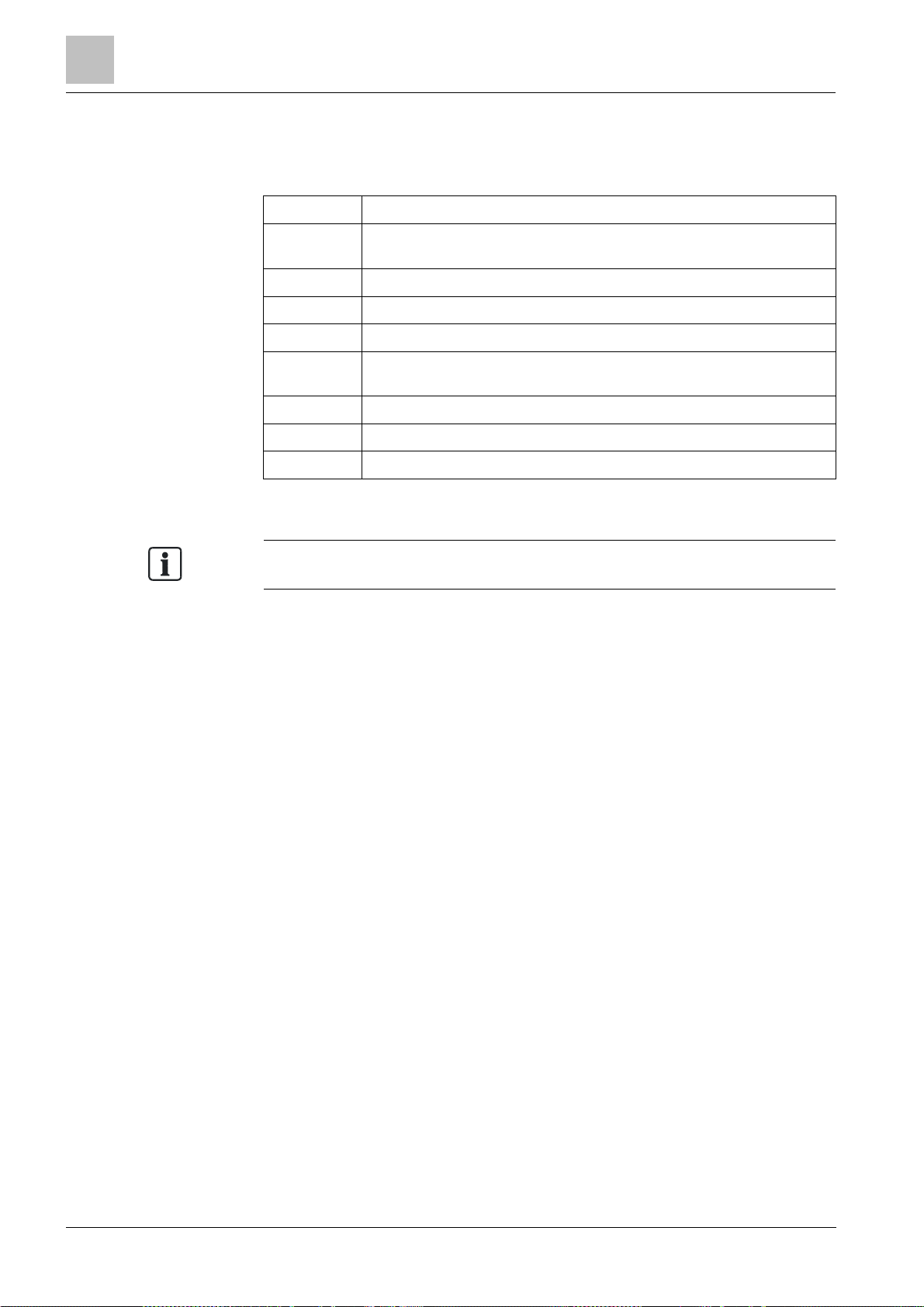
Target groups
The information in this document is intended f or the following target groups:
Target group Activity Qualificat ion
About this document
1
Product Manager
Project Manager
Project engineer
Installation personnel
Maintenance personnel l Carries out all maintenance work.
l Is responsible for information passing
between the manufacturer and regional
company.
l Coordinates the flow of information
between the individual groups of people
involved in a project.
l Coordinates the deployment of all
persons and resources involved in the
project according to schedule .
l Provides the information required to run
the project.
l Sets parameters for product depending
on specific national and/or customer
requirements.
l Checks operability and approves the
product for commissioning at the place
of installation.
l Is responsible for trouble-shooting.
l Assembles and installs the product
components at the place of installation.
l Carries out a performance check
following installation.
l Checks that the products are in perfect
working order.
l Searches for and corrects malfunctions.
l Has obtained suitable specialist training
for the function and for the products.
l Has attended the training courses for
Product Managers.
l Has obtained suitable specialist training
for the function and for the products.
l Has attended the training courses for
Project Managers.
l Has obtained suitable specialist training
for the function and for the products.
l Has attended the training courses for
Product Engineer.
l Has received specialist training in the
area of building installation technology
or electrical installations.
l Has obtained suitable specialist training
for the function and for the products.
There are various tasks that may only be performed by qualified persons in
accordance with the national implementation of Directive 2009/104/EC (e.g. in
Germany: Section 2 (7) of the Ordinance on Industrial Safety and Health
(BetrSichV)).
Source language and reference document
l The source/original language of this document is G erman (de).
l T he reference version of this document is the international version in English.
The international ver sion is not localized.
Document identification
The document ID is structured as follows:
ID code Examples
ID_ModificationIndex_Language_COUNTRY
-- = multilingual or international
A6V10215123_a_de_DE
A6V10215123_a_en_-A6V10315123_a_--_--
Date format
The date format in the document corresponds to the recomm endation of
international standard ISO 8601 (format YYYY-MM-DD).
Building Technologies A6V10367521_h_en_-Fire Safety 2015-02-02
9
About this document
Applicable documents
The 'i' sy
mbol identifies supplementary informat ion and tips for an easier way of
1
Conventions for text marking
Markups
Special markups are shown in this document as follows:
⊳ Requirement for a behavior instruction
1.
Behavior instruction with at least two operation sequences
2.
– Version, option, or detailed information for a behavior instruction
⇨ Intermediate result of a behavior instruction
⇨ End result of a behavior instruction
l
Numbered lists and behavior instructions with an operation
sequence
[➙ X] Reference to a page number
'Text' Quotation, reproduced identically
<Key> Identificat ion of keys
Supplementary information and tips
working.
See also
2 Applicable documents [➙ 11]
10
Building Technologies A6V10367521_h_en_--
Fire Safety 2015-02-02

Applicable documents
1.1 Applicable documents
You will also find inform ation about search variants and links t
o mobile
Document ID Title
About this document
1
001204
001227 Installation instructions Shunt Zener Diode SB2, SB3
001519 Installation instructions Input / output module DC1192
007228
008250 Technical Manual Line tester FDUL221
009122 Technical manual Input/output module (transponder) FDCIO223
A6V10208532 Installation Sealing element FDBZ295
A6V10208546
A6V10208552 Installation Detector locking device FDBZ293
A6V10210416
A6V10210424 FS720 Fire detection system - Configuration
A6V10260486
A6V10324618
A6V10331076
A6V10333771 Technical Manual Line adapter (Ex) FDCL221-Ex
A6V10367523 Installation Automatic fire detector OOH740-A9-Ex
A6V10371417 Data sheet Automatic fire detector OOH740-A9-Ex
A6V10414910 Technical manual Zone module, external powered FDCI723
A6V10443621
Principles, applications, installation, maintenance Fire alarm signal in
areas at risk of explosion
Data Sheet Test equipment and accessories FDUD291, FDUD292,
FDUD293, RE6, RE7T, RE8ST, RE8STCO, RE10, FDUM291,
FDUM292, FDUL221, Sinteso-Test, FDUD29x-E
Installation Detector base FDB20x/FDB201-AA, FDB22x/FDB221-AA,
Base attachment FDB291, Detector designation plate FDBZ291,
Dummy detector FDX291
FS720 Fire detection system - Commissioning, Maintenance,
Troubleshooting
Installation Alarm indicators, adapter frame, surface-mounted housing,
indicator housing, incl. washer FDAI92EX, FDAI93EX, AI330,
DCA1191, DJZ1193
Planning, Mounting/Installation, Commissioning, Maintenance of fire
detection installations with addressed detector lines in potentially
explosive atmospheres
Installation Base attachment wet FDB295, Detector designation plate
DBZ1193A, Protective cage DBZ1194, EMC-protective cage FDBZ294
Modernizing fire detection installations with multiple protocol detectors
in potentially explosive atmospheres
Please also observe the documentation for your fire detection system.
1.2 Download center
You can download various types of documents, such as data sheets, installation
instructions, and license texts v ia the following Internet address:
http://siemens.com/bt/download
l Ent er the document ID in the 'Find by keyword' input box.
applications (apps) for various systems on the home page.
Building Technologies A6V10367521_h_en_-Fire Safety 2015-02-02
11
About this document
Technical terms, abbreviations, and formula symbols
The symbols
used correspond to t he EN
60079
-
11 standard.
1
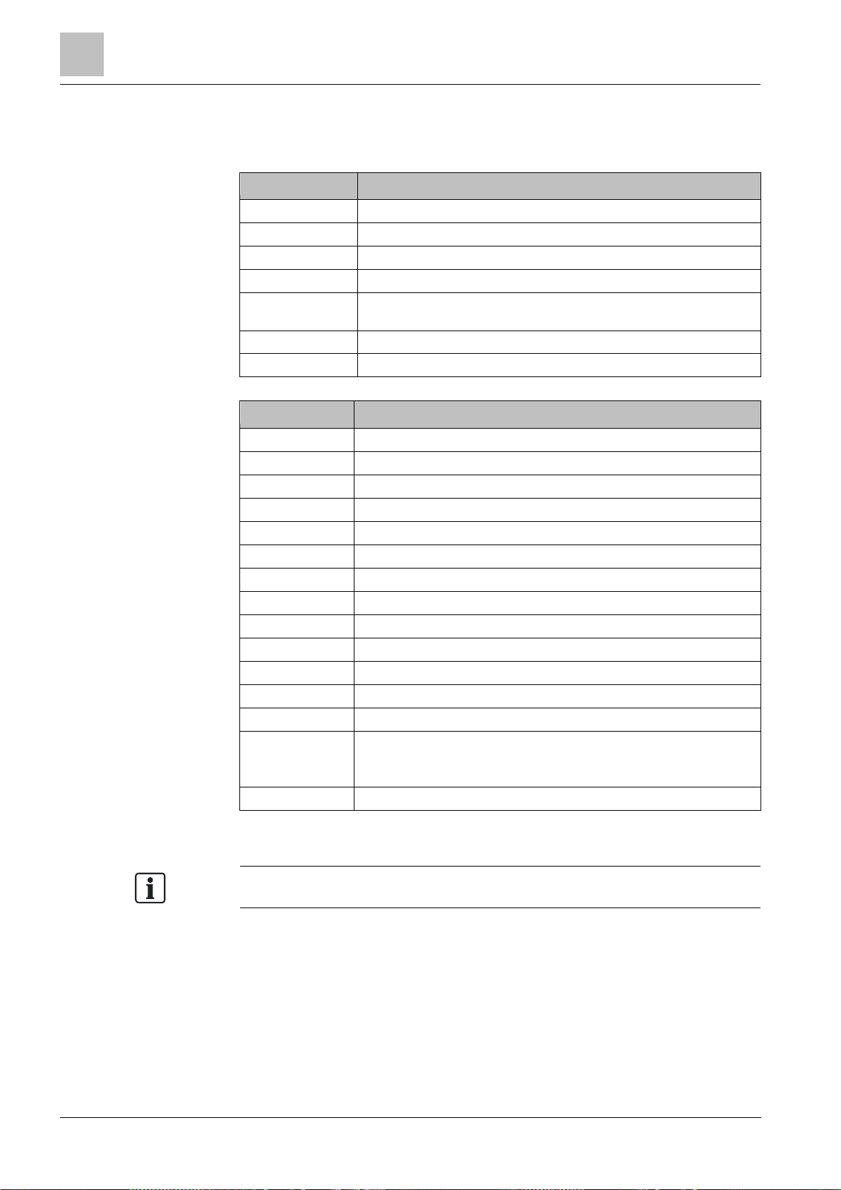
1.3 Technical terms, abbreviations, and formula symbols
Term Explanation
AI Alarm indicator
ASA Advanced Signal Analysis
ES Product version
C-NET Addressed detector line
C-NET-Ex
K-MK Maximum current connection factor on a collective detector line
LED Light-emitting diode
Symbol Meaning
Addressed detector line in a potentially explosive atmosphere
downstream of a line adapter (Ex) FDCL221-Ex
C
0
C
C
C
i
I
0
I
i
L
0
L
C
L
i
P
0
P
i
R
C
T
a
U
i
U
m
Maximum external capa city
Maximum permissible cable capacitance
Maximum internal capacity
Maximum output current
Maximum input current
Maximum external inductivity
Maximum permissible cable inductance
Maximum internal inductivity
Maximum output power
Maximum input power
Resistance of the connection cable
Ambient temperature in a potentially explosive atmosphere
Maximum input voltage
Maximum r.m.s. value of the alternating voltage.
Maximum permissible voltage of an associated item of electrical
equipment without canceling the energy limitation.
U
0
Maximum output voltage
You will find more technical terms in the glossary at the end of this document.
12
Building Technologies A6V10367521_h_en_--
Fire Safety 2015-02-02

Revision history
1.4 Revision history
The first edition of a language version or a country variant may, for example, b
e
The reference docum ent's version applies to all languages into which the reference
document is trans lated.
version 'd' inst ead of 'a' if the reference document is already this version.
The table below shows this document's revision history:
Modification index Edition date Brief description
About this document
1
h 2015-02-02
g 2014-07-22 Editorial changes
f 2014-05-08 Editorial changes
e 2014-02-04
d 2013-04-30 'Technical Ambient Supervision Alarm' added; editorial changes
c 2012-08-17 Labels adapted; Annex added
b 2012-06-15 Editorial changes
a 2012-05-11 First edition
Table listing published language versions corrected; base attachment wet
FDB295 added as optional accessory; sealing element FDBZ295 added; IP
protection category amended in 'Technical data' chapter; editorial changes
Changes in chapter: parameter sets for addressed operation; editorial
changes
The table below shows the published language versions with the corresponding
modification index:
Modification index en_-- de_- - fr_-- it_-- es_--
h X X X X X
g X X X X X
f – X – – –
e – X – – –
d X X – – –
c – X – – –
b – X – – –
a – X – – –
X = published
– = no publication with this modification index
Building Technologies A6V10367521_h_en_-Fire Safety 2015-02-02
13
2
Safety instructions
Contradictory safety instructions
protection.
Safety
2 Safety
WARNING
Risk of explosion caused by disregarding safety instr uctions
● Should safety instructions relating to explosion protection contradict other
safety instructions, please observe the safety instructions relat ing to explosion
2.1 Safety instructions
The safety notices mus t be observed in order to protect people and property.
The safety notices in this document contain the following elements:
l Symbol for danger
l Signal word
l Nature and origin of the danger
l Consequences if the danger occurs
l Measures or prohibit ions for danger avoidance
Symbol for danger
This is the symbol for danger. It warns of risks of injury.
Follow all measures ident ified by this symbol to avoid injury or deat h.
Additional dan ger symbols
These symbols indic ate general dangers, the type of danger or poss ible
consequences, measures and prohibitions, examples of which are shown in the
following table:
General danger Explosive atmosphere
Voltage/electric shock Laser light
Battery Heat
14
Building Technologies A6V10367521_h_en_--
Fire Safety 2015-02-02

Safety regulations for the method of operation
Signal word
Nature and origin of the danger
●
Measures / prohibit ions for danger avoidance
Nature and origin of the danger
●
Measures / prohibit ions for danger avoidance
The signal word classifies the danger as defined in the following table:
Signal word Danger level
Safety
2
DANGER
WARNING
CAUTION
NOTICE
DANGER identifies a dangerous situation, which will result directly in deat h or
serious injury if you do not avoid this situation.
WARNING identifies a dangerous situation, which may result in death or serious
injury if you do not avoid this situation.
CAUTION identifies a dangerous situation, which could result in slight to
moderately serious injury if you do not avoid this situation.
NOTICE
observance.
identifies possible damage to property that may result from non-
How risk of injury is presented
Information about the risk of injury is shown as follows:
WARNING
Consequences if the danger oc curs
How possible damage to property is presented
Information about possible damage to property is s hown as follows:
NOTICE
Consequences if the danger oc curs
2.2 Safety regulations for the method of operation
National standards, regulations and legislation
Siemens products ar e developed and produced in compliance with the relevant
European and international safety standards . Should additional national or local
safety standards or legislation concerning the planning, mounting, inst allation,
operation or disposal of the product apply at the place of operation, then these
must also be taken into account together with the safety regulations in the product
documentation.
Building Technologies A6V10367521_h_en_-Fire Safety 2015-02-02
15
2
Safety regulations for the method of operation
Electrical volt age
regulations.
Work carried out by pers onnel who are not qualified
and international direct ives and regulations.
Safety
Electrical installations
WARNING
Electric shock
● W ork on electrical installations may only be carried out by qualified
electricians or by instructed persons work ing under the guidance and
supervision of a qualified electrician, in accordanc e with the electrotechnical
l W herever possible disconnect products from the power supply when carrying
out commissioning, maintenance or repair work on them.
l Lock volt-free areas to prevent them being switched back on again by mistake.
l Label the connection terminals with external external voltage using a
'DANGER External voltage' sign.
l Rout e mains connections to products separately and fuse them with their own,
clearly marked fuse.
l F it an easily accessible disconnecting device in acc ordance with IEC 60950-1
outside the installation.
l Produce earthing as stated in local safety regulations.
Mounting, installation, commissioning and maintenance
l If you require tools such as a ladder, these must be safe and must be intended
for the work in hand.
l W hen starting the fire control panel ensure that unstable conditions cannot
arise.
l Ensure that all points listed in the 'Testing the product operability' section below
are observed.
l You may only set controls to normal function when the product operability has
been completely tested and the system has been handed over to the customer.
WARNING
Risk of explosion
● W ork in potentially explosive areas may only be carried out by qualified
specialists or by specially instructed persons, in accordance with the national
l You must only mount, install, and test the devices if the atmosphere in the area
is not at risk of explosion.
16
Building Technologies A6V10367521_h_en_--
Fire Safety 2015-02-02

Safety
Safety regulations for the method of operation
2
Testing the product operability
l Prevent the remot e transmis sion from trigger ing err oneously.
l I f testing building installations or activating devices from third-party companies,
you must collaborate with the people appointed.
l T he activation of fire control installations for test purposes must not cause
injury to anyone or damage to the building installations. The following
instructions m ust be observed:
l Use the correct potential for activation; this is generally the potential of the
building installation.
l O nly check controls up to t he interface (relay with blocking option).
l Mak e sure that only the controls to be tested are activated.
l I nform people before testing the alarm devices and allow for possible panic
responses.
l I nform people about any noise or mist which may be produced.
l Bef ore testing the remote transmission, inform the corresponding alarm and
fault signal receiving stations.
Modifications to the system design and the products
Modifications to the system and to individual products m ay lead to faults,
malfunctioning and safety risks. Written confirmation must be obtained from
Siemens and the corresponding safety bodies for m odifications or additions.
No changes may be made to devices with EC-type examination certificates.
Modules and spare parts
l Components and spare parts must comply with the technical specifications
defined by Siemens. Only use products specified or recommended by
Siemens.
l Only use fuses with t he specified fuse characteristics.
l Wrong battery types and improper battery changing lead to a risk of explosion.
Only use the same battery type or an equivalent battery t ype recommended by
Siemens.
l Bat teries must be disposed of in an environmentally friendly manner. Observe
national guidelines and regulations.
Disregard of the safety regulations
Before they ar e delivered, Siemens products ar e tested to ensure they function
correctly when used properly. Siemens disclaims all liability for damage or injuries
caused by the incorrec t application of the instructions or the disregard of danger
warnings contained in the documentation. This applies in particular to the following
damage:
l Per sonal injuries or damage to property caused by improper use and incorrect
application
l Per sonal injuries or damage to property caused by disregarding safety
instructions in the documentation or on the product
l Personal injury or damage to property caused by poor maintenance or lack of
maintenance
Building Technologies A6V10367521_h_en_-Fire Safety 2015-02-02
17
2
Standards and directiv
es complied with
We are grateful for any suggestions for improvement.
Limited or non
-
existent fire detect
ion
detection installation.
Incorrect planning and/or configurat ion
detection installation.
Safety
Disclaimer
We have checked that the content of this document matches the hardware and
software described. Despite this, we cannot rule out deviations and cannot
therefore assume liability for them matching completely. The details in this
document are checked regularly and any corrections needed included in
subsequent editions.
2.3 Standards and directives complied with
A list of the standards and directives complied wit h is available from your Siemens
contact.
2.4 Release Notes
Limitations t o the configuration or use of devices in a fire detection installation with
a particular firmware version are possible.
WARNING
Personal injury and damage to property in the event of a fire.
● Read the 'Release Notes' before you plan and/or configure a fire detection
installation.
● Read the 'Release Notes' before you carry out a firmware update to a fire
NOTICE
Important st andards and specifications are not satisfied.
Fire detection installation is not accepted f or commissioning.
Additional expense result ing from necessary new planning and/ or configuration.
● Read the 'Release Notes' before you plan and/or configure a fire detection
installation.
● Read the 'Release Notes' before you carry out a firmware update to a fire
18
Building Technologies A6V10367521_h_en_--
Fire Safety 2015-02-02
Structure and function
Setup
C-NET-Ex
C-NET
3 Structure and functio n
3.1 Setup
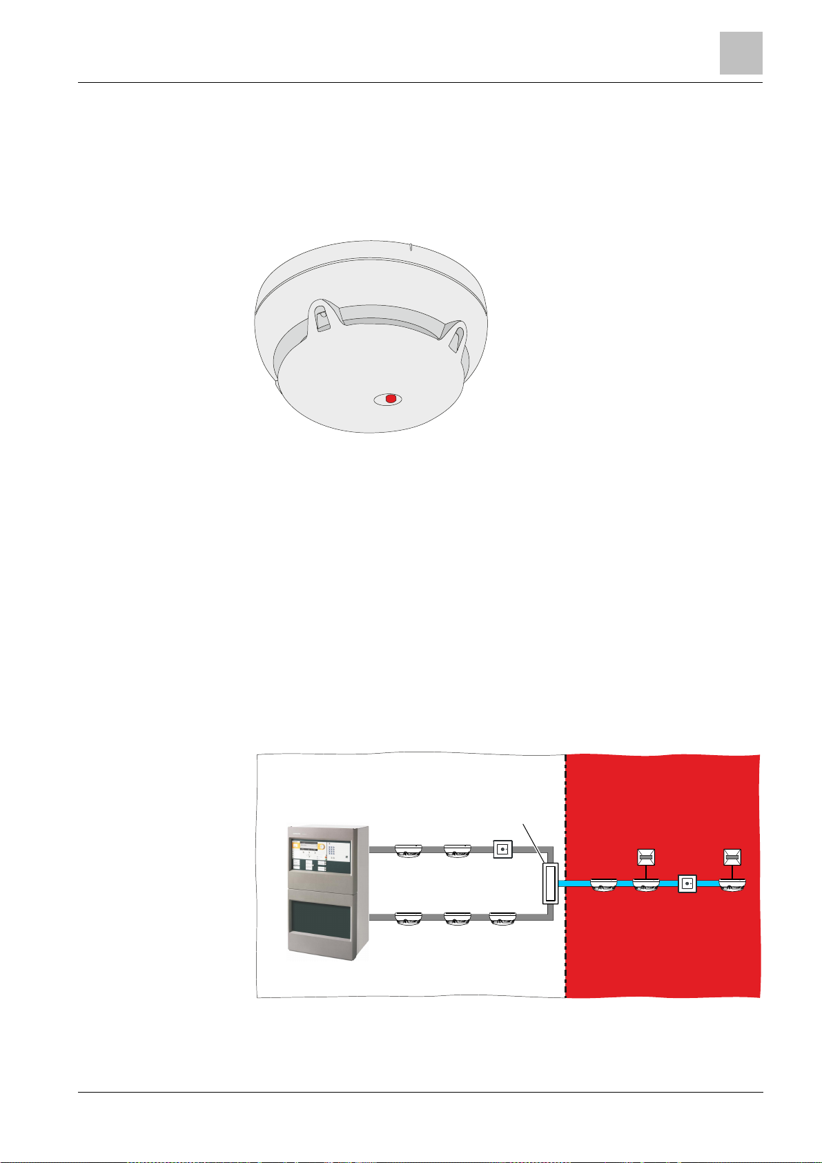
3.1.1 Point detector OOH740-A9-Ex with ASAtechnology
3
View of point detector OOH740-A9-Ex
Properties
l Signal processing with ASA
l Can be used either addressed to the C-NET-Ex detector line or to collective Ex
detector lines
l Can be set as neural fire detector, wide-spectrum smoke detector or heat
detector on the software side
l Selectable detection behavior thanks to application-specific ASA parameter
sets
l Adjustable monitoring of ambient temperature based on hysteresis. The
configuration is set with the 'Cerberus-Engineering-Tool' software.
l Indication of the condition (alarm, localization or test) by means of a red LED
l Mount ing on the C-NET-Ex downstream of a line adapter (Ex) FDCL221-Ex
l W ith collective detector lines, mounting downstream of an input/output module
DC1192 or FDCIO223 or a zone module FDCI723 and a safety barrier SB2 or
SB3
Area not at risk Ex area
technology
FDCL221-Ex
FC72x
Use of several point detectors OOH740-A9-Ex on the C-NET-Ex downstream of a line
adapter (Ex) FDCL221-Ex
19
Building Technologies A6V10367521_h_en_-Fire Safety 2015-02-02
Structure and function
Setup
2
3
4
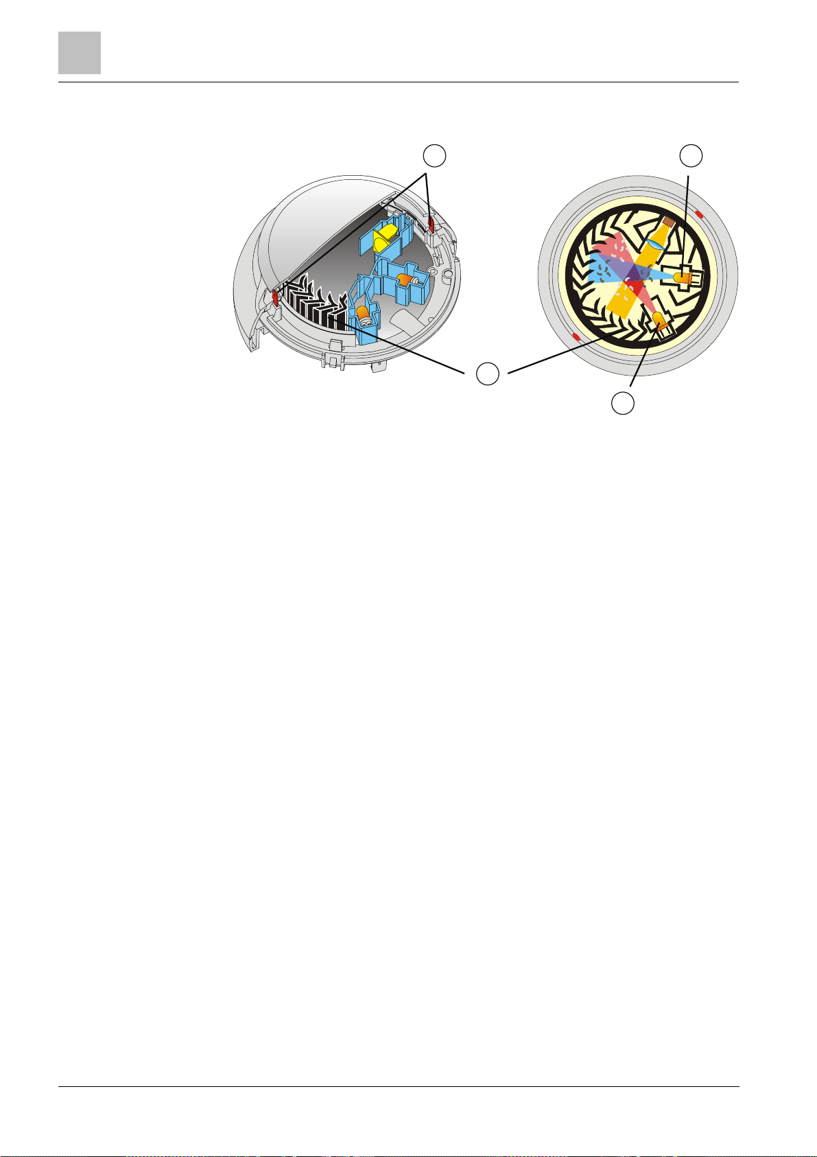
1
Heat sensors
3
Forward scatterer
2
Backward scatterer
4
Labyrinth
3
Setup of the point detector
The point detector OOH740-A9-Ex has two optical and two thermal sensors.
1
The detector has a sophisticated opto-electronic measuring chamber with two
optical transmitters, an optical receiv er, and two thermal sensors.
The transmitt ers illuminate the smoke par ticles from different angles. One sensor
acts as forward scatterer, the other as backward scatterer. The scattered light then
hits the receiver (photodiode) and generates a measurable elect ric signal.
The combination of a forward and backward scatt erer facilitates an optimum
detection and the dif ferentiation of light and dark par ticles, which leads to a
homogenous response behavior and optimizes the differentiation of wanted signals
and deceptive phenomena.
In addition, the heat sensors make it possible to detect fires without smoke
generation.
The combination of optical and thermal sensor signals optim izes detection
reliability. This has the following advantages:
l Early detection of all types of fire, whether they generate light or dark smoke, or
no smoke at all.
l The multisensor fire detector can be operated at a lower sensitivity level and
thus achieves a higher immunity against false alarms, which can be caused by
cold aerosols (e.g., by smoking). In the case of an open fire, the smoke
sensitivity is heightened by the temperature increase, which means that a
detection reliabilit y level that is compar able to that of the wide-spectrum sm oke
detector can be achiev ed.
The detector can also be used pur ely as an optical smoke detector or purely as a
heat detector. T his is determined by selecting one of the following sensor modes:
l Sensor mode 0: Applic ation as neural fire detector
l Sensor mode 1: Application as heat detector
l Sensor mode 2: Application as smoke detector
20
Building Technologies A6V10367521_h_en_--
Fire Safety 2015-02-02
See also
2 Applicable documents [➙ 11]
Setup
3.1.2 Features of fire detection functionality
The point detector OOH740-A9-Ex has the following features in terms of its fire
detection functions:
l Dynamic influence on the parameter sets
l Pattern recognition
l Real time int erpretation of the situation
l Process- and time-controlled switchover of the parameter sets
Signal processing is based on ASAtechnology (ASA = Advanced Signal Analysis).
ASAtechnology can als o be characterized as second generation algorithms. Signal
processing with ASAtechnology allows for opt imum adaptation of detector behavior
to the corresponding ambient conditions.
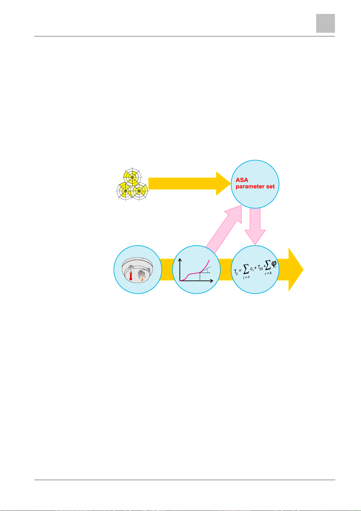
Operating mode: Signal processing with ASAtechnology
The figure below shows signal processing in the form of a diagram:
Structure and function
3
Environment
Evaluation of the
situation
Dynamic influence
of parameter
Danger
level
C
Signal analysisSensory
Signal processing with ASAtechnology
Sensory
The signals captured by the sensory are transmitted to the algorithm. The
algorithms are set by selec t ing the parameter set.
Algorithms
In comparison t o the det ection algorithms (DA), the individual parameters of the
selected parameter set can be adapted with ASAtechnology. A r eal time
interpretation of the situation leads to a dynamic influence on the algorithm. T he
real time interpr etation results in a broadening of the application range of the
parameter set and thus of the detector. The detector reacts more sensitively in the
event of fire, and more robustly in the event of deceptive phenomena.
Algorithms
Result
21
Building Technologies A6V10367521_h_en_-Fire Safety 2015-02-02
Structure and function
Setup
The 'Technical Ambient Supervision Message' c annot be configured on all fire
Warning level for
T echnical Am bient
Result
Sensory
3
Switching over the parameter set
In addition to selecting the parameter set, the point detectors with ASAtechnology
enable time- or process-controlled switching ov er of the parameter sets
(Manned/Unmanned swit chover). The time- or process-controlled switching over of
parameter sets allows the detector to be used in places where the situation
changes significant ly on a regular basis (e.g. kitchens, production halls).
Parameter sets which can be loaded
The detectors have several permanently programmed parameter sets. For special
applications new, addit ional parameter sets can be downloaded in the field
(depending on the control panel) .
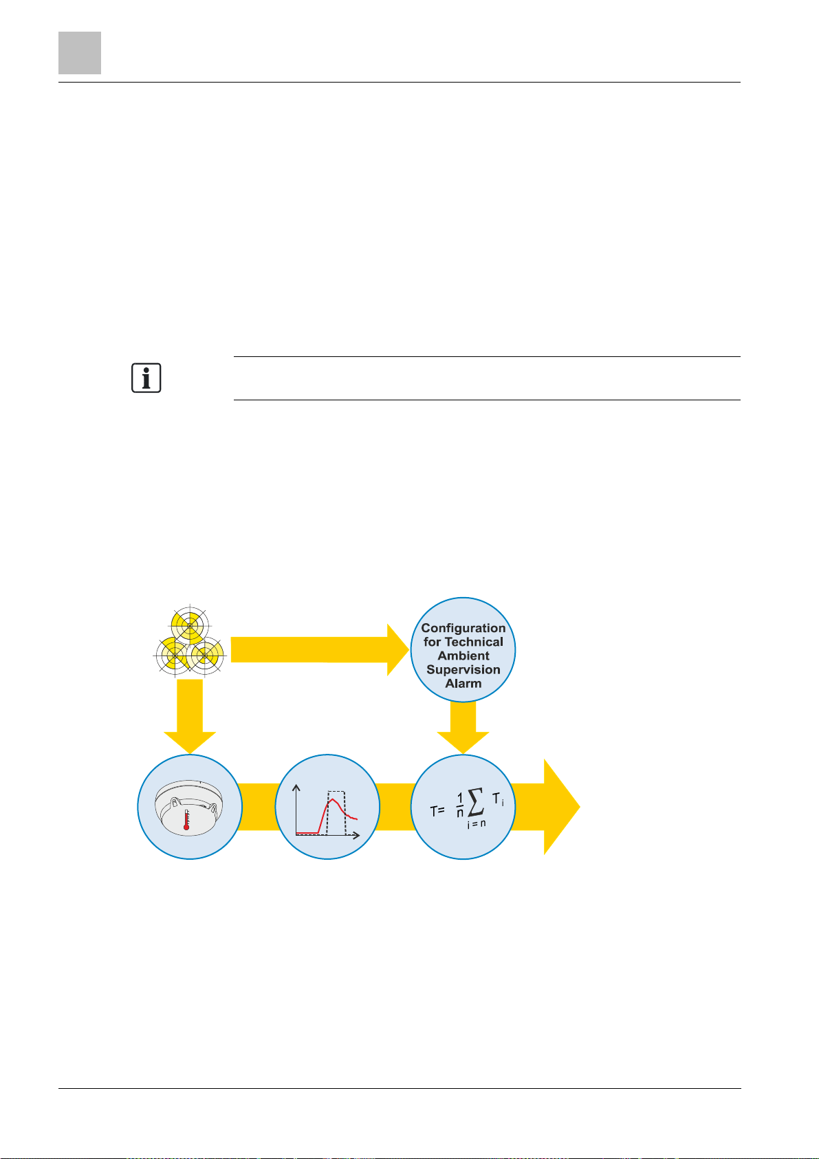
3.1.3 Features of the 'Technical Ambient Supervision Message'
control panels. Observe the information in the 'List of compatibility'.
'Technical Ambient Supervision Message' mode det ects an increase in
temperature c aused by hysteresis above a specified threshold.
Temperature monitoring compares the current measured temperature with a preset
threshold value.
You can configure t he following parameters for the point detector:
l Threshold value for temperature
l Alar ming when the temperature threshold value is exceeded or undershot
l Hysteresis range
Parameter conf iguration is carried out using the soft ware 'Cerberus-EngineeringTool'.
Environment:
Temperature
T [°C]
°C
Signal analysis
Signal processing by the 'Technical Ambient Supervision Message'
t
Supervision Alarm
Algorithms
22
Building Technologies A6V10367521_h_en_--
Fire Safety 2015-02-02
 Loading...