

Siemens OOH740, OOHC740 Technical Manual
OOH740, OOHC740
Bui
lding Technologies
Automatic fire detectors
Technica l Manual
A6V10305793_m_en_-2016-02-15 Control Products and Systems

Legal notice
Building Technologies
A6V10305793_m_en_
--
Fire Safety
Legal notice
Technical specifications and availability s ubject to change without notice.
Transmitt al, reproduction, diss emination and/or editing of this document as well as
utilization of its contents and communication thereof to others wit hout express
authorization are prohibited. Off enders will be held liable for payment of damages.
All rights creat ed by patent grant or registration of a utilit y model or design patent
are reserved.
Issued by:
Siemens Switzerland Ltd.
Building Technologies Div ision
International Headquarters
Gubelstrasse 22
CH-6301 Zug
Tel. +41 41 724-2424
www.siemens.com/buildingtechnologies
Edition: 2016-02-15
Document ID: A6V10305793_m_en_--
© Siemens Switzerland Lt d, 2010
2 | 108
2016-02-15

Building Technologies
A6V10305793_m_en_
--
Table of contents
1 Ab ou t thi s doc um e nt ............................................................................. 7
1.1 Applicable documents ................................................................................. 9
1.2 Download center ......................................................................................... 9
1.3 Technical terms .........................................................................................10
1.4 History of changes .....................................................................................10
2 Sa fet y ............................................................................................... 1 3
2.1 Safety instructions .....................................................................................13
2.2 Safety regulations for the method of operation ...........................................15
2.3 Standards and directives complied with......................................................17
2.4 Release Notes ...........................................................................................17
3 Str u ct ur e an d fun c ti o n ......................................................................... 18
3.1 Overview ...................................................................................................18
3.1.1 Multi-s enso r smoke dete c tor, ASA O OH7 40 ................................19
3.1.2 Neura l fire d e te ctor OOHC7 4 0 ....................................................20
3.1.3 Feature s of fire de tectio n functio nality .........................................21
3.1.4 Feature s of the 'Te chnica l CO Alarm' ..........................................22
3.1.5 Features of the 'Technical Ambient Supervision Message' ...........24
3.1.6 Detail s for orderi ng ......................................................................24
3.1.7 Product vers i on ES .....................................................................25
3.2 Setup .........................................................................................................26
3.2.1 Structure of OOH74 0 ..................................................................26
3.2.2 Structure of OOHC740 ................................................................27
3.3 Function ....................................................................................................30
3.3.1 Parame ter sets ...........................................................................30
3.3.1.1 Parameter sets for fire detection ...................................31
3.3.1.2 Parameter sets for 'Technical CO Alarm' ......................34
3.3.2 Dange r le ve l s and wa rn i n g le vels ................................................35
3.3.2.1 Danger levels for fire detection .....................................35
3.3.2.2 Warning levels for CO ..................................................36
3.3.2.3 Danger levels for 'Technical Ambient Supervision
Message'36
3.3.3 Diagn osis levels ..........................................................................37
3.3.4 Line separator .............................................................................38
3.3.5 Internal alarm indicator in the case of ES <20 (OOH740 and
OOHC740 ) ................................................................................................38
3.3.6 External alarm indicator in the case of ES <20 (OOH740 and
OOHC740 ) ................................................................................................39
3.3.7 Advanced flashing behavior of the alarm indicators in the case of
ES ≥20 (OOH 740 and O OHC740 ) .............................................................40
3.3.8 Conne ctio n for external alarm indi cato rs ......................................42
3.3.9 Renova tion mode ........................................................................42
Fire Safety
3 | 108
2016-02-15

Building Technologies
A6V10305793_m_en_
--
Fire Safety
3.3.10 Test mode .................................................................................. 42
3.3.11 Behavior in degraded mode ........................................................ 43
3.3.12 Line tester ................................................................................... 44
3.4 Mechanical setup ....................................................................................... 44
3.5 Accessories ............................................................................................... 45
3.5.1 Detecto r base with loop contac t DB721 ....................................... 45
3.5.2 Detecto r base DB722 .................................................................. 4 5
3.5.3 Detecto r base DB721D ............................................................... 4 6
3.5.4 Detecto r base (collecti ve) DB110 ................................................ 4 6
3.5.5 Sound er base DBS720 ............................................................... 4 7
3.5.6 Desig nation plate FDBZ291 ........................................................ 47
3.5.7 Detecto r base seal RS720 .......................................................... 47
3.5.8 Base attachmen t BA720 ............................................................. 48
3.5.9 Base attachment wet BA721 ....................................................... 48
3.5.10 Designation plate DBZ1193A ...................................................... 48
3.5.11 Detector heating unit FDBH291 ................................................... 49
3.5.12 Protective cage DBZ1194 ........................................................... 49
3.5.13 Detector locking device LP720 .................................................... 49
3.5.14 Micro terminal DBZ1190-AA ........................................................ 50
3.5.15 Connection terminal DBZ1190-AB............................................... 50
3.5.16 Parameter set resistor 33 kΩ PSR720-1 ...................................... 50
3.5.17 Parameter set resistance 68 kΩ PSR720-2 ................................. 50
4 Planning ............................................................................................51
4.1 Compatibility .............................................................................................. 51
4.2 Fire detection ............................................................................................. 51
4.2.1 Ambient features ......................................................................... 51
4.2.2 Parame ter sets: Sen sor mode 0 'Neura l fire dete ctor' .................. 53
4.2.2.1 Description ................................................................... 53
4.2.2.2 Use .............................................................................. 55
4.2.2.3 Specification ................................................................ 56
4.2.3 Parame ter sets: Sensor mode 1 'Heat detector' ........................... 57
4.2.4 Parame ter sets: Sen so r mode 2 'Smoke dete c tor' ....................... 58
4.2.4.1 Description ................................................................... 58
4.2.4.2 Use .............................................................................. 59
4.2.4.3 Specification ................................................................ 59
4.2.5 Parame ter sets for collecti ve operation ........................................ 60
4.2.5.1 Description ................................................................... 60
4.2.5.2 Use .............................................................................. 60
4.2.5.3 Specification ................................................................ 61
4.2.6 Defaul t setting s for opera ting on the C-N ET ................................ 61
4.2.7 Setting the para me ter se t in col le cti ve ope rati o n.......................... 62
4.2.8 Sample appli catio ns for OOH740 ................................................ 62
4.2.9 Sample applica tions for OOHC74 0 .............................................. 63
4 | 108
2016-02-15

Building Technologies
A6V10305793_m_en_
--
4.3 Technical CO alarm ...................................................................................64
4.3.1 Parame ter sets for the 'Technical CO Alarm' ...............................64
4.3.1.1 Description ...................................................................64
4.3.1.2 Use ..............................................................................65
4.3.1.3 Specification.................................................................66
4.3.1.4 Default settings ............................................................67
4.3.1.5 Application examples ...................................................67
4.3.2 Ambien t feature s .........................................................................68
4.4 Technical Ambient Supervision Message ...................................................69
4.4.1 Ambien t feature s .........................................................................69
4.4.1.1 Temperature monitoring ...............................................71
4.4.1.2 CO monitoring ..............................................................71
4.4.2 Config urati on ..............................................................................72
4.4.3 Defaul t settings ...........................................................................72
5 Mo u nt i ng / In s ta l l a ti o n ......................................................................... 73
5.1 Required space .........................................................................................73
5.2 Detector base DB72x and detector base (collective) DB110 .......................74
5.3 Sounder base DBS720 ..............................................................................76
5.4 Detector base seal RS720 .........................................................................77
5.5 Base attachment BA720 ............................................................................78
5.6 Base attachment wet BA721 ......................................................................79
5.7 Detector locking device LP720 ...................................................................82
5.8 Designation plate FDBZ291 .......................................................................83
5.9 Cable entry ................................................................................................84
5.9.1 Auxili ary terminals DBZ1190-AA/ -AB ...........................................85
5.10 Detector lines ............................................................................................85
5.10.1 Connection diagram, addressed ..................................................85
5.10.2 Connection diagram, collective ....................................................87
5.11 Detector dust cap ......................................................................................89
5.12 Detector heating unit FDBH291 .................................................................90
5.12.1 Installation of the detector heating unit ........................................90
5.12.2 Connection of the detector heating unit .......................................91
5.13 Migrat ion from collective detector line to addressed detector line . .... ..... .... .92
5.13.1 Removing the diode unit..............................................................93
Fire Safety
6 Co mm i ss i on i ng .................................................................................. 9 4
6.1 Commissioning on the C-NET ....................................................................94
6.2 Commissioning on a collective detector line ...............................................94
7 Ma in te na nc e / Repa i r .......................................................................... 9 5
7.1 Performance check ....................................................................................95
5 | 108
2016-02-15

Building Technologies
A6V10305793_m_en_
--
Fire Safety
7.2 Testing the point detector .......................................................................... 95
7.2.1 Test mode on the contro l panel ................................................... 96
7.2.2 Testing the fire detectio n function ali ty.......................................... 9 7
7.2.3 Testing the CO fun ctio na li ty (only for OOH C7 40 ) ........................ 97
7.2.4 Testing the functionality of the 'Technical Ambient
Superv ision Message' ................................................................. 98
7.2.4.1 'Technical Ambient Supervision Message'
performa nce check ....................................................... 98
8 Sp eci fi cat io ns .....................................................................................9 9
8.1 Technical data for OOH740 ....................................................................... 99
8.2 Technical data for OOHC740 ................................................................... 102
8.3 Dimensions ............................................................................................. 104
8.4 Environmental compatibility ..................................................................... 104
Ind ex ....................................................................................................... 105
6 | 108
2016-02-15

About this document
Applicable documents
108
A6V10305793_m_en_
--
Fire Safety
1 About this document
Goal and purpose
This document contains all the inform ation you'll need on automatic fire detectors
● OOH740
● OOHC740
Following the instruc tions consistently will ensure that the product can be used
safely and without any problems.
Intended use
The automatic fire detectors OOH740 and OOHC740 may only be used on a C-
NET detector line in a FS720 fire detection system.
The automatic fire detector OOH740 may also be used on a collective detector line
or a conventional detector line.
Target groups
The information in this document is int ended for the following target groups :
Target group Activity Qualificatio n
1
Product Manager
Project Manager
Project engineer
Installation pers onnel
● Is responsible for information
passing between the manuf acturer
and regional company.
● Coordinates the flow of information
between the individual groups of
people involved in a project.
● Coordinates the deployment of all
persons and resources involved in
the project according to schedule.
● Provides the information required to
run the project.
● Sets parameters for product
depending on specific national
and/or customer requirements.
● Checks operability and approves
the product for commissioning at the
place of installation.
● Is responsible for troubleshooting.
● Assembles and installs the product
components at the place of
installation.
● Carries out a performance check
following installation.
● Has obtained suitable specialist
training for the function and for the
products.
● Has attended the training courses
for Product Managers.
● Has obtained suitable specialist
training for the function and for the
products.
● Has attended the training courses
for Project Managers.
● Has obtained suitable specialist
training for the function and for the
products.
● Has attended the training courses
for Product Engineer.
● Has received specialist training in
the area of building installation
technology or electrical installations.
Maintenance personnel ● Carries out all maint enance work.
Building Technologies
● Has obtained suitable specialist
● Checks that the products are in
perfect working order.
● Searches for and corrects
malfunctions.
training for the function and for the
products.
Source language and reference document
● The source/original language of this document is German (de).
● The reference version of this document is the international version in E nglish.
The international ver sion is not localized.
7 |
2016-02-15

About this document
Applicable doc
uments
1
Building Technologies
A6V10305793_m_en_
--
Fire Safety
The 'i' symbol identifies supplementary information and t
ips for an easier way of
Document identification
The document ID is structured as follows:
ID code Examples
ID_Modificat ionIndex_Language_COUN
TRY
-- = multilingual or international
A6V10215123_a_de_DE
A6V10215123_a_en_-A6V10315123_a_--_--
Date format
The date format in the document corresponds to the recommendation of
international standard ISO 8601 (format YYYY-MM-DD).
Conventions for text marking
Markups
Special markups are shown in this document as follows :
⊳ Requirement for a behavior instruction
1.
2.
– Version, option, or detailed information for a behavior instruction
⇨ Intermediate result of a behavior instruction
⇨ End result of a behavior instruction
●
Behavior instruction with at least two operation sequences
Numbered lists and behavior instructions with an operation
sequence
[➙ X] Reference to a page number
'Text' Quotation, repr oduced identically
<Key> Identificat ion of keys
>
Relation sign and for ident ification between st eps in a sequence,
e.g., 'Menu bar' > ' Help' > 'Help topics'
↑ Te xt Identification of a glossary entry
Supplementary information and tips
working.
8 | 108
2016-02-15

About this document
Applicable documents
108
A6V10305793_m_en_
--
Fire Safety
1.1 Applicable documents
You will also find inform ation about search variants and links to mobil
e
Document ID Name
008250 Technical Manual Line tester FDUL221
1
009122
Technical manual Input/output module ( transponder)
FDCIO223
A6V10200373
Installation Det ector base with loop contact DB721,
DB722, detector base DB720, sounder base DBS720,
detector base seal RS 720, detector locking device
LP720, base attachment BA720
A6V10201731
Installation Det ector exchanger DX791, adapt er for
detector exchanger FDUD491
A6V10210416
FS720 Fire detection system - Commissioning,
Maintenance, Troubleshooting
A6V10210424 FS720 Fire detection system - Configuration
A6V10229261 List of compatibility (for 'Cerberus™ PRO' pr oduct line)
A6V10254740
Operating instructions Solo461 heat detector tester kit
RE7T
A6V10284161
Data sheet Automatic fire detectors OOH740,
OOHC740
A6V10316300
Installation Det ector base (collective) DB110, DB110D,
DB110R, DB110RD, detector base seal RS720,
detector locking device LP720, base attachment BA720
A6V10323905
Installation Det ector base DB721D, detector base seal
RS720, detector locking device LP720
A6V10406006
Please also observe the documentation for your fire detection system.
1.2 Download center
You can download various types of documents, such as data sheets, installat ion
instructions, and license texts via the following Internet address:
http://siemens.com/bt/download
l Enter t he document ID in the 'Find by keyword' input box.
applications (apps) for various sy stems on the home page.
Installation Bas e attachment wet BA721, Detector
designation plate DBZ1193A, Protective cage
DBZ1194, EMC-protective cage FDBZ294
Building Technologies
9 |
2016-02-15

About this document
Technical terms
1
Building Technologies
A6V10305793_m_en_
--
Fire Safety
The first edition of a language version or a country variant may , for example, be
1.3 Technical terms
Term Explanation
AI Alarm indicator
ASA (ASA
technology
CO Carbon monoxide
EAI External alarm indic ator
EOL End-of-line
ES Product version
C-NET Addressed detect or line
IAI Internal alarm indicator
LED Light-emitting diode
TM
) Advanced Signal Analysis
MAK value
Maximum concentration at the workplace: maxim um
permissible concent ration of a toxic substance in the air
at the workplace
1.4 History of changes
The reference docum ent's version applies to all languages into which the reference
document is trans lated.
version 'd' inst ead of 'a' if the reference document is already this version.
The table below shows this document's revision history:
10 | 108
2016-02-15

About this document
History of changes
108
A6V10305793_m_en_
--
Fire Safety
Modificatio n in dex Editio n da te Brief description
m
l 2014-05-08
k 2013-04-04
j 2013-01-25
2016-02-15
● Intende d us e ad de d
● Extended flash ing behav ior of th e alarm i ndicators added
● Additions to the 'Detector base DB72x and detector bas e ( collective) DB110'
chapter
● EMC-protective cage FD BZ294 remove d as accessory part
● Temperature ranges for 'Technical Ambient Supervision Message' corrected
● Editorial changes
● Changes in the following chapters :
– 'Multi-sensor smoke detector, ASA OOH740'
– 'Neura l fire detector OOHC740'
– 'Structure of OOHC740'
– 'Parameter sets for fire detection'
– 'Behavi or in degrad ed m od e op eration'
– 'Line separators'
– 'External alarm indicator in the case of ES <20 (OOH740 and OOHC740)'
– 'Extend ed flashi ng behavior of the alarm indicators in the case of ES ≥20
(OOH740 and OOHC740)'
– 'Detector base DB722'
– 'Compatibility'
– 'Fire detection' > 'Spec ification'
– 'Parameter sets: Sensor m ode 0 'Neural fire detector' ' > 'Des cription'
– 'Parameter sets: Sensor m ode 0 'Ne ural fire detector' ' > 'Application'
– 'Parameter sets: Sensor mode 2 smoke detector > 'Description'
– 'Parameter sets: Sensor mode 2 smoke detector > 'Application'
– 'Parameter sets for collective operation' > 'Specification'
– 'Default settings for operating on the C-NET'
– 'Sam ple applications for OOH740'
– 'Sample applications for OOHC740'
– 'Parameter sets for the 'Technical CO Alarm' ' > 'Description'
– 'Parameter sets for the 'Technical CO Alarm' ' > 'Specification'
– 'Parameter sets for the 'Technical CO Alarm' ' > 'Sample a pplications'
– 'Technical 'Ambient Supervision' Mes s age' > 'A mb ient features'
– 'Detector base DB72x and detector base (collective) DB110'
– 'Base attachment BA720'
– 'Connec tio n diagra m, ad dressed'
– 'Connection di agram, collective'
– 'Migration from collective detector line to addressed detector line'
– 'Testing the fire detection functionality'
– 'Testing the CO functionality'
– ' 'Technical Ambient Supervis ion Message' function check'
– 'Technical data'
● 'Danger levels for 'T echnical Ambient Supervision Mes sage' ' chapter corrected
Data she et in 'Applicable documents' c hapter added; new parameter sets add ed;
'Technical Ambient S upervis ion Message' made available in point detector OOH740;
various changes in the 'Specifications' chapter; editorial changes; base attachment
wet BA721, designation plate DBZ1193A, protective cage DBZ1194, EMC-protec tive
cage FDBZ294, and detector heating unit FDBH291 added, 'Download center'
chapter added; addition parameter sets for OOH740 added; changes made to
'Compatibility' chapter
Technical data adapted
LPCB appr ov als ad ded
1
Building Technologies
11 |
2016-02-15

About this document
History of changes
1
Building Technologies
A6V10305793_m_en_
--
Fire Safety
The language versions and country variants produced by a local company have
Modificatio n
en_--de_--fr_--it_--es_
--
Modificatio n in dex Editio n da te Brief description
i 2012-08-16
h 02.2012
g 11.2011
f 09.2011
e 06.2011
d 05.2011
c 02.2011
b 12.2010
a 07.2010
Details concerning product version corrected in 'Planning' chapter; notice added:
Parameter sets 'Balanced CO' and 'Suppression CO' do not have LPC B approval;
date format changed in accordance with specifications of ISO 8601 (format: yyy ymm-dd)
Detector base DB722 and base attachment BA7 20 added , marine approva l for
OOH740 added
OOH740: VdS approval and CPD n umber added
IP protec tion categories adapted
Chapter 'Removing the diode unit' adde d
Detector base DB110 a dded
Removing the d iode unit on the detector base DB721D changed; detector
designations changed
Editori al revision; detector base DB721D added
First editi on
the same modification index as the corresponding reference document. They are
not however included in the t able below.
The table below shows the published language versions with the corresponding
modification index:
index
m X X X X X
l X X X X X
k X X X X X
j X X X X X
i X X X X X
h X X X X X
g X X X X X
f X X X X X
e X X X X X
d X X X X X
c – X – – –
b X X – – –
a – X – – –
X = published
– = no publication with this modification index
12 | 108
2016-02-15
Safety
Safety instructions
108
A6V10305793_m_en_
--
Fire Safety
2 Safety
2.1 Safety instructions
The safety notices mus t be observed in order to protect people and property.
The safety notices in this document contain the following elements:
● Symbol for danger
● Signal word
● Nature and origin of the danger
● Consequences if the danger oc curs
● Measures or prohibitions for danger avoidance
Symbol for danger
This is the symbol for danger. It warns of risks of injury.
Follow all measures ident ified by this symbol to avoid injury or death.
Additional dan ger symbols
These symbols indic ate general dangers, the type of danger or possible
consequences, measures and prohibitions, examples of which are shown in the
following table:
2
General danger Explosive atmosphere
Voltage/electric shock Laser light
Battery Heat
Signal word
The signal word classifies the danger as defined in the following table:
Signal word Danger level
DANGER
WARNING
CAUTION
NOTICE
DANGER identifies a dangerous situation, which will result directly in death or
serious injury if you do not avoid this situation.
WARNING identifies a dangerous situation, which may result in death or s erious
injury if you do not avoid this situation.
CAUTION identif ies a dangerous situat ion, which could result in slight to
moderately serious injury if you do not avoid this situation.
NOTICE
observance.
identifies possible damage to property that may result from non-
Building Technologies
13 |
2016-02-15
Safety
Safety instructions
2
Building Technologies
A6V10305793_m_en_
--
Fire S
afety
Nature and origin of the danger
●
Measures / prohibit ions for danger avoidance
Nature and origin of the danger
How risk of injury is presented
Information about the risk of injury is shown as follows:
WARNING
Consequences if the danger oc curs
How possible damage to property is presented
Information about possible damage to proper ty is shown as follows:
NOTICE
Consequences if the danger oc curs
● Measures / prohibit ions for danger avoidance
14 | 108
2016-02-15
Safety
Safety
regulations for the method of operation
108
A6V10305793_m_en_
--
Fire Safety
2.2 Safety regulations for t he method of operation
Electrical volt age
regulations.
National standards, regulations and legislation
Siemens products ar e developed and produced in compliance wit h the relevant
European and international safety standards. Should additional national or local
safety standards or legislation concerning the planning, mounting, installation,
operation or disposal of the product apply at the place of operation, then these
must also be taken into account together with the safety regulations in the product
documentation.
Electrical installations
WARNING
Electric shock
● Work on electric al installations may only be carried out by qualified
electricians or by instructed persons working under the guidance and
supervision of a qualified electrician, in acc ordance with the elect rotechnical
2
● Wherever possible disconnect products from the power supply when carrying
out commissioning, maintenance or repair work on them.
● Lock volt-free areas to prevent them being switched back on again by mistake.
● Label the connection terminals with external external voltage using a
'DANGER External voltage' sign.
● Route mains connect ions to products separately and fuse them with their own,
clearly marked fuse.
● Fit an easily accessible disconnecting devic e in accordance with IEC 60950-1
outside the installation.
● Produce earthing as stated in local safety regulations.
Mounting, installation, commissioning and maintenance
● If you require tools such as a ladder, these must be safe and must be intended
for the work in hand.
● When starting the fire control panel ensure that unstable conditions c annot
arise.
● Ensure that all point s listed in the 'Testing the product operability' section below
are observed.
● You may only set controls to normal function when the product operability has
been completely tested and the system has been handed over to the customer.
Building Technologies
15 |
2016-02-15

Safety
Safety regulations for the method of operation
2
Building Technologies
A6V10305793_m_en_
--
Fire S
afety
Testing the product operability
● Prevent the remote transmission from triggering erroneously.
● If testing building installations or activating devices from third-party companies,
you must collaborate with the people appointed.
● The activation of fire control installations for test purposes must not cause
injury to anyone or damage to the building installations. The following
instructions m ust be observed:
– Use the correct potential for activation; this is generally the potential of the
building installation.
– Only check controls up to the interface (relay with blocking option).
– Make sure that only the controls to be tested are activated.
● Inform people before testing the alarm devic es and allow for possible panic
responses.
● Inform people about any noise or mist which may be produced.
● Before testing t he remote transmission, inform the corresponding alarm and
fault signal receiving stations.
Modifications to the system design and the products
Modifications to the system and to individual product s may lead to faults,
malfunctioning and safety risks. Written confirmation must be obtained from
Siemens and the corresponding safety bodies f or modifications or additions.
Modules and spare parts
● Components and spare part s must comply with the technical specifications
defined by Siemens. Only use products specified or recommended by
Siemens.
● Only use fuses wit h the specified fuse characteristics.
● Wrong battery ty pes and impr oper battery changing lead t o a risk of explosion.
Only use the same battery type or an equivalent battery type recommended by
Siemens.
● Batteries must be disposed of in an environmentally friendly manner. Observe
national guidelines and regulations.
Disregard of the safety regulations
Before they ar e delivered, Siemens product s are tested to ensure they function
correctly when used properly. Siemens disclaims all liability for dam age or injuries
caused by the incorrec t application of the inst ructions or the disregard of danger
warnings contained in the documentation. This applies in particular to the following
damage:
● Personal injuries or damage to property caused by improper use and incorrect
application
● Personal injuries or damage to property caused by disregarding safety
instructions in the documentation or on the product
● Personal injury or damage to property caused by poor maintenance or lack of
maintenance
16 | 108
2016-02-15
Safety
Standards and directives complied with
108
A6V10305793_m_en_
--
Fire Safety
2.3 Standards and directives compl ied with
Limited or non
-
existent fire detection
detection installation.
Incorrect planning and/or configuration
detection installation.
A list of the standards and directives com plied with is available from your Siemens
contact.
2.4 Release Notes
Limitations t o the configuration or use of devices in a fire detection installation with
a particular firmware version are possible.
WARNING
Personal injury and damage to property in t he event of a fire.
● Read the 'Release Notes' before you plan and/or configure a fire detection
installation.
● Read the 'Release Notes' before you carry out a firmware update to a fire
2
NOTICE
Important st andards and specifications are not satisfied.
Fire detection installation is not accept ed for commissioning.
Additional expense result ing from necessary new planning and/or configuration.
● Read the 'Release Notes' before you plan and/or configure a fire detection
installation.
● Read the 'Release Notes' before you carry out a firmware update to a fire
Building Technologies
17 |
2016-02-15
Structure and function
Overview
3
Building Technologies
A6V10305793_m_en_
--
Fire Safety
Multi-
sensor smoke detector, ASA
Neural fire det ector
3 Structure and functio n
3.1 Overview
In this document t he following point detectors are referred to collectively using the
term 'Automatic fire detectors':
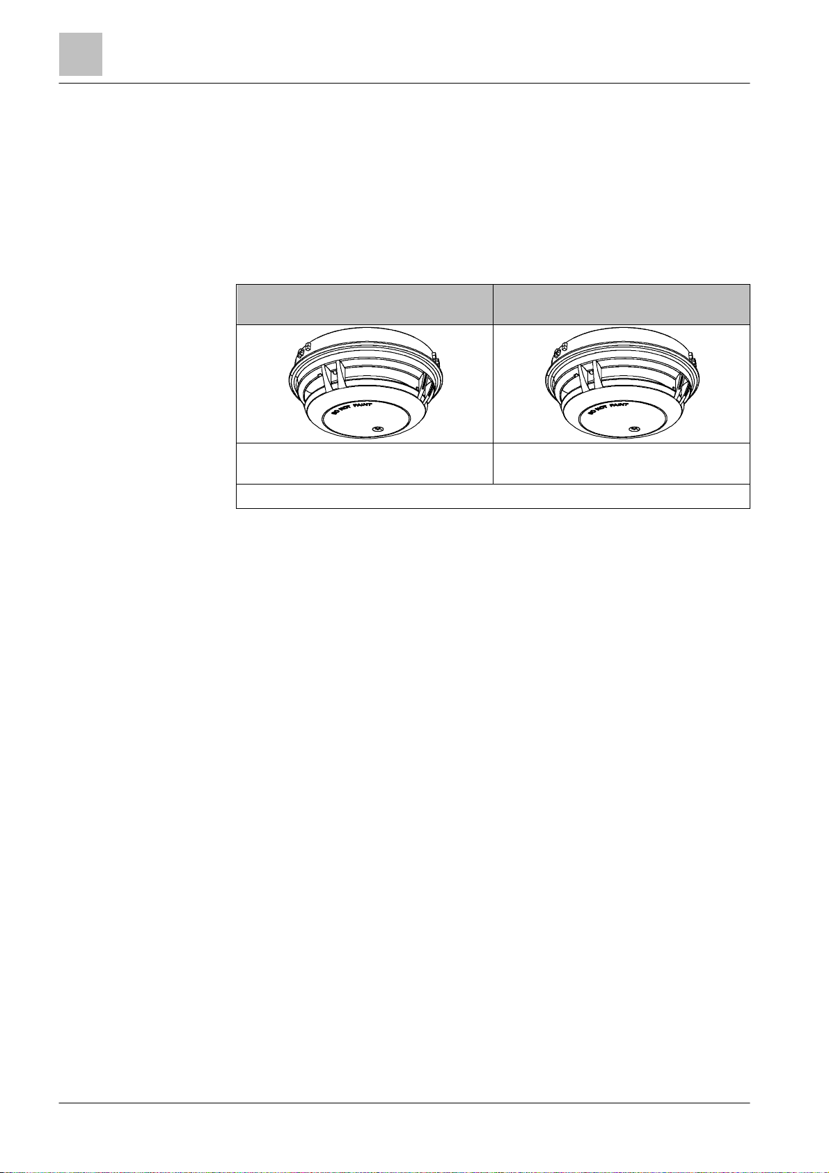
● Multi-sensor smoke detector, ASA OOH740
● Neural fire detector OOHC740
OOH740
Can be used addressed in the C-NET
and in collective mode
Detection behavior can be selected
OOHC740
Can be used addressed on the C-NET
18 | 108
2016-02-15
Structure and function
Overview
108
A6V10305793_m
_en_
--
Fire Safety
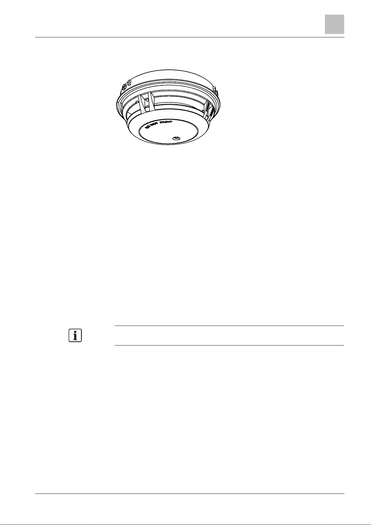
3.1.1 Multi-sensor smoke detector, ASA OOH740
Check the version of your
FS720
control panel. Some features ar e only available
Figure 1: Multi-sensor smoke detector, ASA OOH740
Properties
● Communication via C-NET (addressed detector line)
● Address automat ically issued during commissioning
● Can also be used on collective detector lines in conjunction with the detector
bases DB721D and DB110
● Built-in line separator
● Signal processing with ASA
(application-specific ASA parameter sets)
● Software can be us ed to set as:
– Neural fire detector
– Wide-spectrum smoke detector
– Heat detector
● Red LED as alarm indicator
● The following funct ions are also included from point detector product version
[➙ 25] ES ≥20:
– 'Technical Ambient Supervision Message' mode can be selected
– Extended flashing behavior of the internal alarm indicator
– Additional 'Super Sensitive' and 'Ultra Sensitive' parameter sets
technology
and optional detection behavior
3
Building Technologies
as of certain versions. You will find details in the 'List of compatibility'.
19 |
2016-02-15
Structure and function
Overview
3
Building Technologies
A6V10305793_m_en_
--
Fire Safety
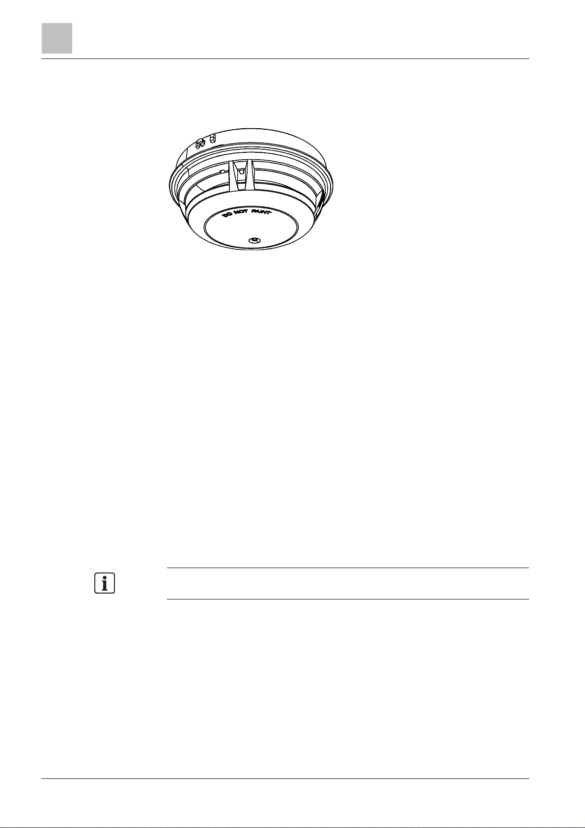
Check the version of your
FS720
control panel. Some features ar e only available
3.1.2 Neural fire detector OOHC740
Figure 2: Neural fire detector OOHC740
Properties
● Communication via C-NET (addressed detector line)
● Address automat ically issued during commissioning
● Built-in line separator
● Signal processing with ASA
(application-specific ASA parameter sets)
● Software can be us ed to set as:
– Neural fire detector
– Neural CO-supported fire detector
– Wide-spectrum smoke detector
– Heat detector
● Detection behavior of the 'Technical CO Alarm' can be set regardless of the
ASA parameter sets fo r fire detection. Can be set using software.
● 'Technical CO Alarm': Detection of carbon monoxide (CO) at concent rations of
5 ppm CO or more (MAK value=30 ppm CO)
● 'Technical Ambient Supervision Mes sage': Adjustable hysteresis-induced
ambient monitoring of temperature or carbon m onoxide. Can be set using
software.
● From point detector product version [➙ 25] ES ≥20: Extended flashing behavior
of the internal alarm indicator
● Red LED as alarm indicator
technology
and optional detection behavior
as of certain versions. You will find details in the 'List of compatibility'.
20 | 108
See also
2 Applicable documents [➙ 9]
2016-02-15
Structure and function
Overview
108
A6V10305793_m
_en_
--
Fire Safety
3.1.3 Features of fire detection functionality
Properties
● Dynamic influence on the param eter sets
● Pattern recognition
● Real time interpr etation of the situation
● Process- and time-controlled switchover of the parameter sets
Signal processing of t he point detectors is based on ASA
Advanced Signal Analysis). ASA
generation algorithms". Signal processing with ASA
adaptation of detector behavior to the corresponding ambient conditions.
Point detectors withASA
technology
reliability and very high resist ance to deceptive phenomena.
technology
can also be characterized as "second
are characterized by their unique detect ion
technology
technology
3
(ASA =
allows for optimum
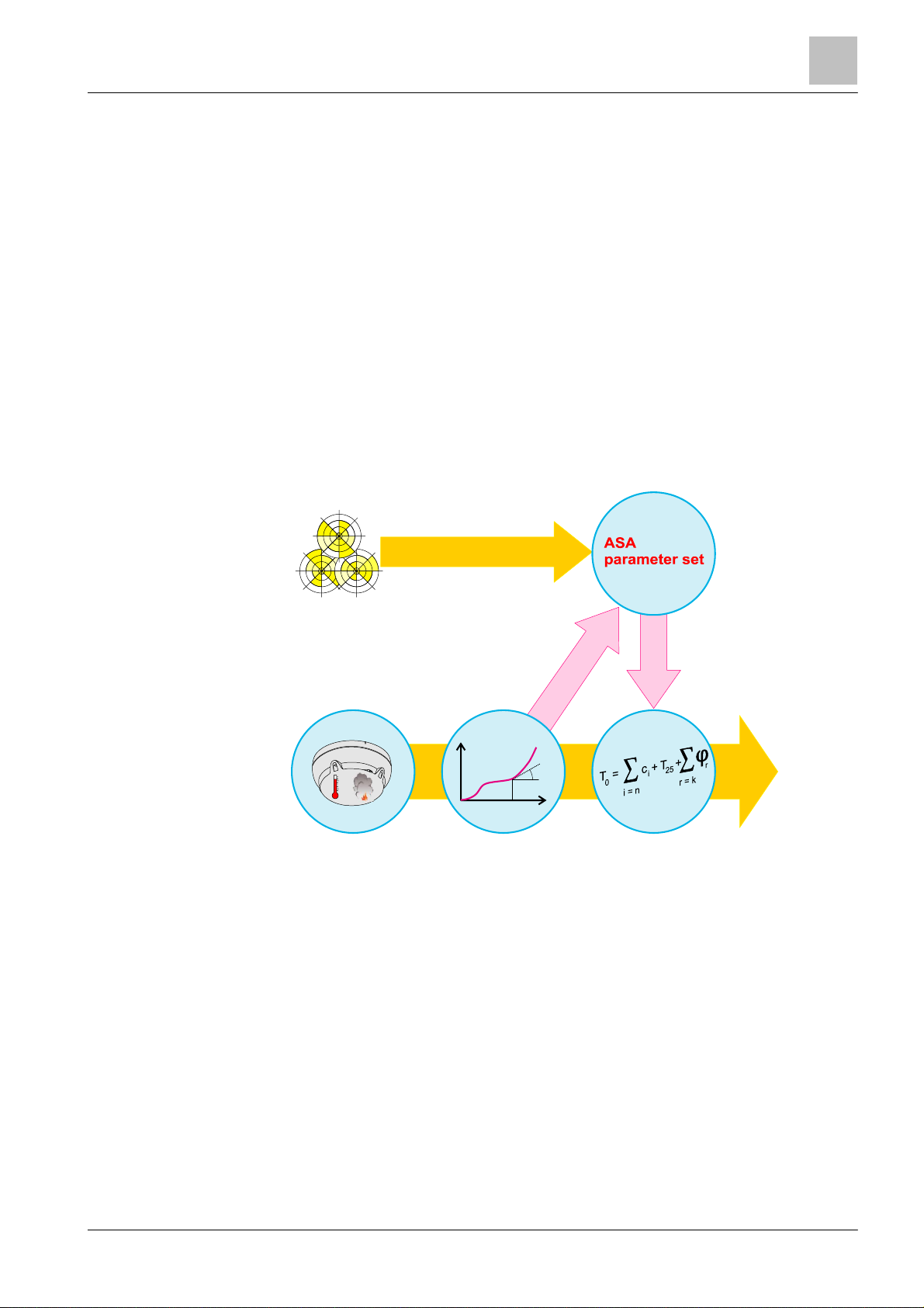
Operating mode: Signal processing with ASA
technology
The figure below shows signal processing on point detectors with ASA
in the form of a diagram:
Environment
Evaluation of the
situation
C
Signal analysisSensory
Algorithms
Dynamic influence
of parameter
technology
Danger
level
Result
Building Technologies
Figure 3: Signal processing with ASA
technology
Sensory
The signals captured by the sensory are transmitted to the algorithm. The
algorithms are set by selec t ing the parameter set.
Algorithms
The individual parameters in the selected parameter set can be adapted with
ASA
technology
. A real time interpretation of the situat ion leads t o a dynamic
influence on the algorithm. This results in the parameter set's and therefore the
point detector's application range broadening. The detector reacts more sensitively
in the event of fire, and more robustly in the event of deceptive phenom ena.
21 |
2016-02-15
Structure and function
Overview
3
Building Technologies
A6V10305793_m_en_
--
Fire Safety
The 'Technical CO Alar m' mode can only be selected on the point detector
Warning lev el
Technical CO alarm
Result
Signal analysis
Sensory
Algorithms
Switching over the parameter set
In addition to selec ting the parameter set, the point detectors wit h ASA
enable time- or process-controlled swit ching over of the parameter sets
(Manned/Unmanned swit chover). Thanks to this function, the detector can be used
in places where the situation changes regularly and f requently (e.g. kitchens,
production halls).
Downloadable parameter s ets
Point detectors withASA
technology
have several permanently progr ammed
parameter sets. For special applications new, additional parameter sets can be
downloaded in the field (depending on the control pane l).
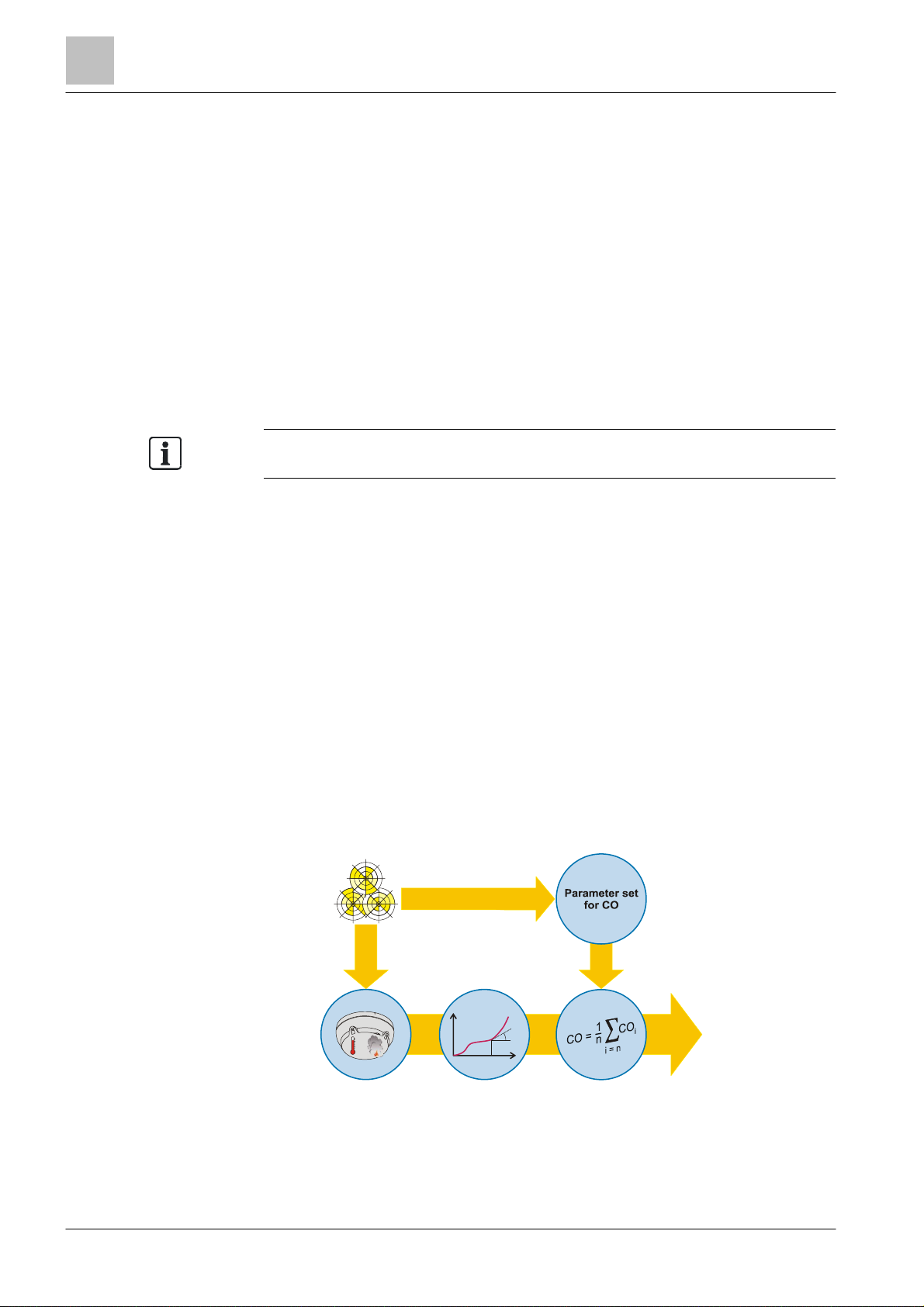
3.1.4 Features of the 'Technical CO Alarm'
OOHC740.
Alongside its fire detection functionality, the point detector also has a CO detection
functionality with the following features:
● Static or dynamic alarm profiles
● Real time interpr etation of the situation
● Process- and t ime-controlled switchov er of the parameter sets for CO
Signal processing by the 'Technical CO Alarm' is undert aken regardless of CO
signal processing for the fire detection f unctionality with the 'S uppression CO' and
'Balanced CO' parameter sets.
The signal processing f eature of the 'Technical CO Alarm' enables optimum
calculation of t he CO concentration. The electro-chemical cell allows the best
possible level of accuracy to be obtained depending on the ambient conditions.
The point detector's CO detection is characterized by the ability f or parameters to
be set and a relatively low cross-sensitivity to other gases, e.g. ethanol or
hydrogen (H2).
technology
22 | 108
Function of the Technical CO Alarm's signal processing
The figure below shows CO signal pr ocessing in the form of a diagram:
Environment:
CO and other
gases
CO
CO
°C
Figure 4: Signal processing by the 'Technical CO Alarm'
t
2016-02-15

Structure and function
Overview
3
108
A6V10305793_m
_en_
--
Fire Safety
Functionality of the 'Technical CO Alarm'
control panel.
The system is not controlled as laid d
own in EN
54-2
equipment in accordance with EN
54-2.
Sensory
The signals captured by the CO sensor are corrected with regard to CO exposure,
sensor sensitivity, temperature, and aging and supplied to the algorithm. The
algorithms are set by selec t ing the parameter set.
Algorithms
The parameter set can be used to select static and dynamic algorit hms. A real time
interpretation of the ambient conditions r esults in improved measurement
accuracy.
The alarm limits correspond to the specified or proposed limits in the respective
standards.
Switching over of parameter set for the 'Technical CO Alarm'
The point detector allows for the time-or process-controlled independent changing
over of the parameter set for CO (Manned / Unmanned changeover). This function
allows the detect or to be used in places where the situation changes significantly
on a regular basis.
Configurable parameter sets for the 'Technical CO Alarm'
The point detect or has several permanently programmed 'Technical CO Alar m'
parameter sets.
NOTICE
There is a risk of undetected CO exposure if the 'Technical CO Alarm' is not
configured on the cont rol panel
● Use the documentation provided for the fire control panel to ensure that the
parameters you want to set for the 'Technical CO Alarm' are support ed by the
NOTICE
Infringement of the EN 54-2 standard
● The signals for CO detection alone must not be used to control f ire detection
Building Technologies
23 |
2016-02-15
Structure and function
Overview
3
Building Technologies
A6V10305793_m_en_
--
Fire Safety
'Technical Ambient Super
vision Message' mode can only be selected for point
The system is not controlled as laid down in EN
54-2
control fire detection equipment in acc ordance with EN
54-2.
Warning l evel for
T echnical Ambi ent
Result
Signal analysis
Sensory
Algorithms
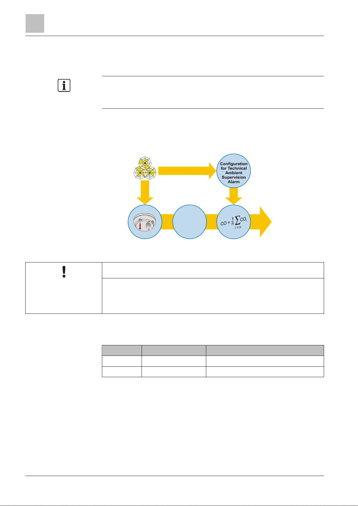
3.1.5 Features of the 'Technical Ambient Supervision Message'
detector OOH740 from product version ES ≥20.
The evaluation of t he CO conc entration in 'Technical Ambient S upervision
Message' mode can only be selected for point detector OOHC740.
In 'Technical Ambient Supervision Message' mode, the point detector can detect
an increase in temperat ure or CO concentration above a specified trigger threshold
caused by hysteresis.
The control panel is used to configure the paramet ers.
Environment:
CO or
temperature
CO
°C
Figure 5: Signal proces sing by t he 'Technical Ambient Supervision Mess age'
NOTICE
Infringement of the EN 54-2 standard
● The signals for CO detection or temperature recording m ust not be used to
3.1.6 Details f or ordering
Type Order no. Designation
OOH740 S54320-F7-A3 Multi-sensor smoke detector, ASA
OOHC740 S54320-F8-A3 Neural fire det ector
Supervision Alarm
24 | 108
2016-02-15
Structure and function
Overview
108
A6V10305793_m
_en_
--
Fire Safety
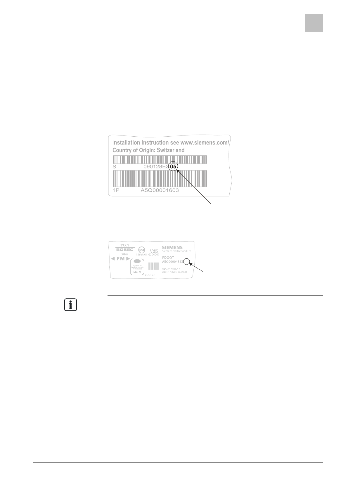
3.1.7 Product versio n ES
Depending on the product and various approvals, the product labels may dif fer in
ES
The product version ES provides the technical st atus of a device in terms of
software and hardware. The product version is provided as a two-digit number.
You will find the det ails of your device's product version:
● On the packaging label
● On the product label or the type plate
Product version on the packaging label
Details of the product version can be found direct ly on the packaging label in the
barcode:
3
Figure 6: Example of a p ackaging label with det ails of the produc t version
Product version on the product label and t he type plate
Details of the product version can be found af ter the device order number:
04
ES
Figure 7: Example of a product label with details of the product version
terms of the informat ion type and layout.
Look for your device' s order number on the product label.
You will find the produc t version after the order number.
Building Technologies
25 |
2016-02-15
Structure and function
Setup
3
Building Technologies
A6V10305793_m_en_
--
Fire Safety
3.2 Set up
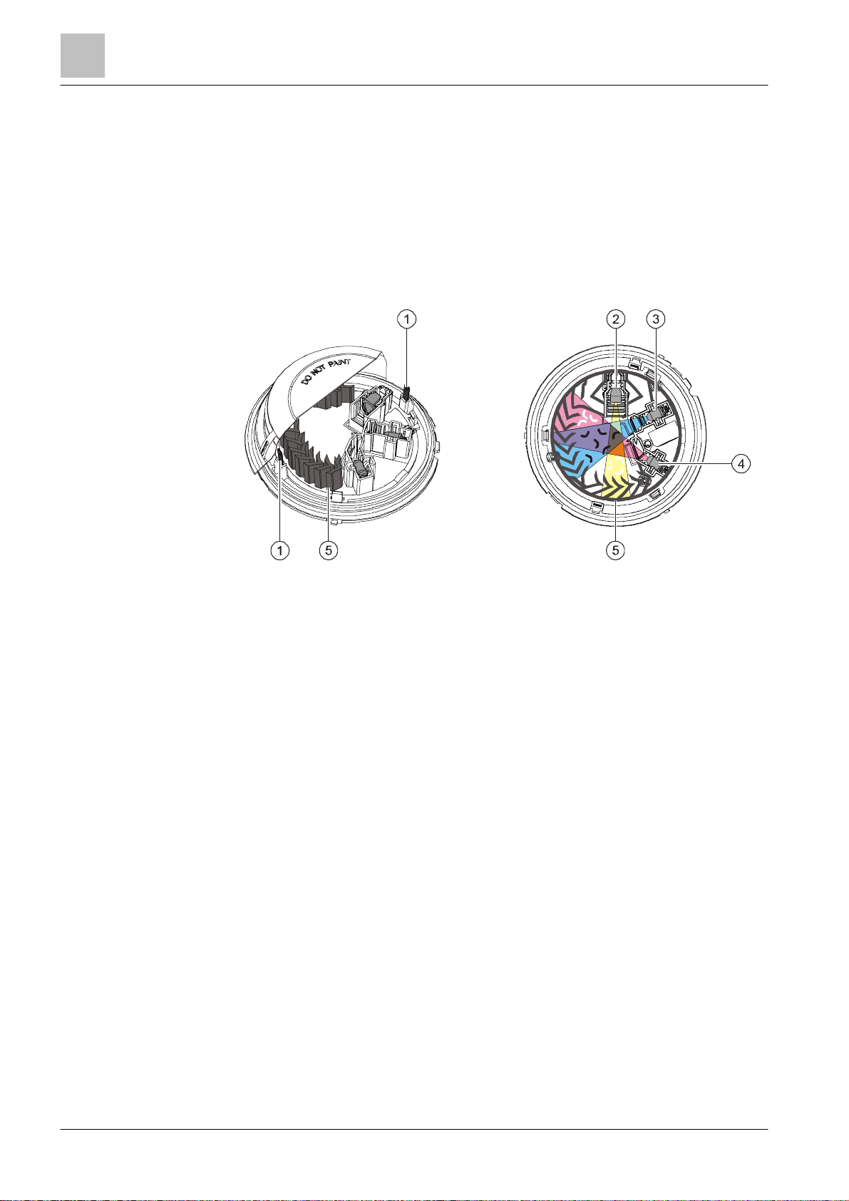
3.2.1 Structure of OOH740
The multi-sensor smoke detector ASA OOH740 is a multi-criteria fire det ector and
has two optical and two thermal sensors.
Structure and function
Figure 8: Sensors of the OOH740
1 Heat sensors 4 Forwar d scatterer
2 Receiver 5 Labyrinth
3 Backward scatterer
The point detect or's high-quality opto-electronic measuring chamber houses the
following components:
● Two optical trans mitters
● One optical receiver
● Two thermal sensors
The transmitt ers illuminate the smoke particles from different angles. One sensor
acts as forward scatterer, the other as backward scatterer. The scatter ed light then
hits the receiver (photodiode) and generates a m easurable electric signal.
The combination of a forward and backward scatterer facilitates an optimum
detection and the dif ferentiation of light and dar k particles, which leads t o a
homogenous response behavior and optimizes the differentiation of wanted signals
and deceptive phenomena.
In addition, the heat sensors make it possible to detect fires without smoke
generation.
26 | 108
2016-02-15
Structure and function
Setup
3
108
A6V10305793_m
_en_
--
Fire Safety
The combination of optical and thermal sensor signals optimizes detection
reliability. This has the following advantages:
● Early detection of all types of fire, whether t hey generate light or dark smok e, or
no smoke at all.
● The neural fire detector can be operated at a lower sensitivity level and thus
achieves a higher immunit y against false alarms which can be caused by cold
aerosols (e.g. by smoking, elect rical welding, etc.). In the case of an open fire,
the smoke sensitivity is heightened by the temperature increas e, which means
that a detection reliabi lity level that is comparable to that of the wide-spectrum
smoke detector can be achieved.
Technical Ambient Supervision Message
'Technical Ambient Supervision Message' mode detects an increase in
temperature above a specified trigger thres hold caused by hysteres is.
You can set the following parameters:
● Temperature t hreshold value
● Messaging when the temperature threshold value is exceeded or undershot
● Hysteresis range
The 'Technical Ambient Supervision Message' is configured using the 'CerberusEngineering-Tool' sof tware.
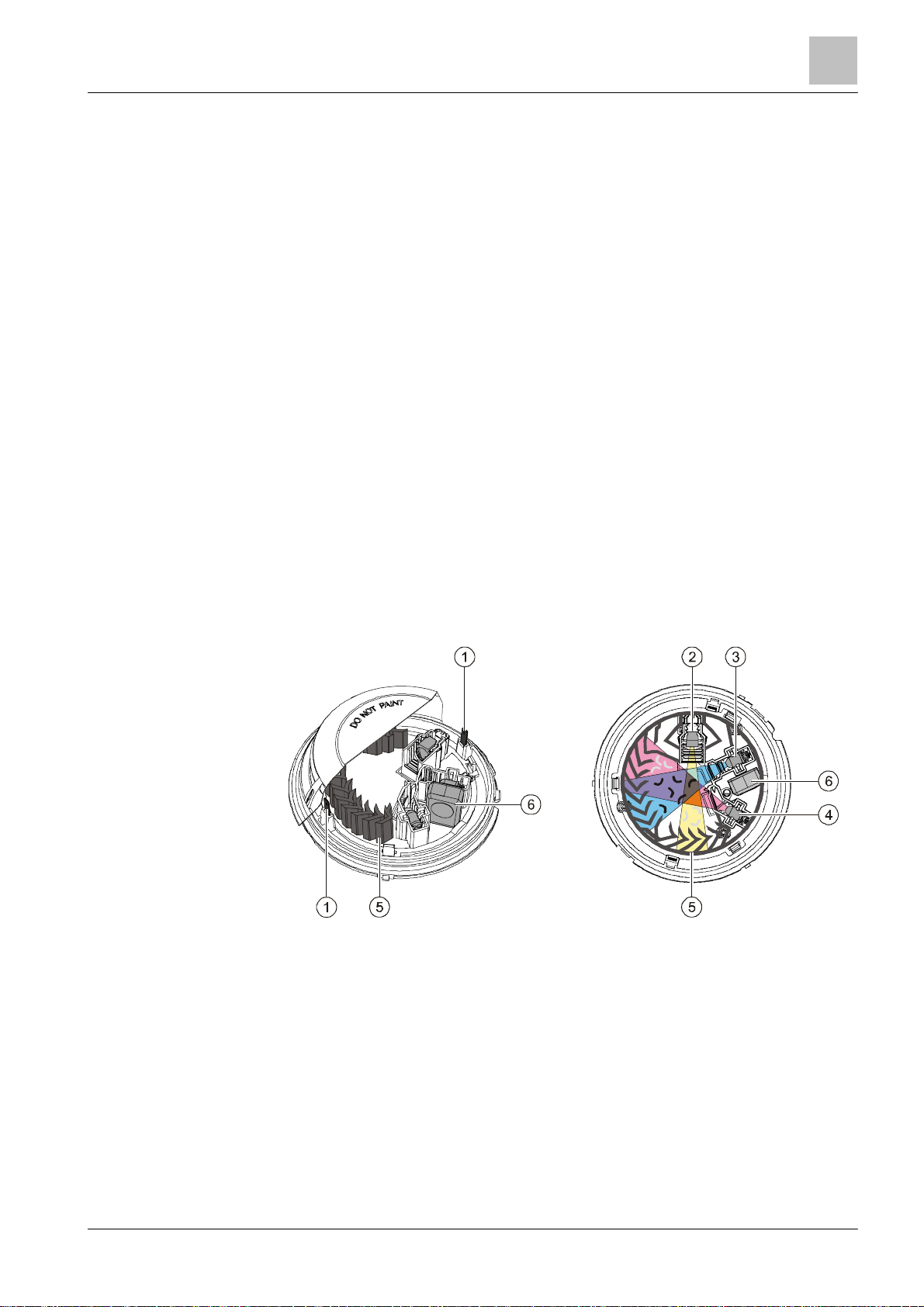
3.2.2 Structure of OOHC 740
The neural fire detector OOHC740 is a multi-c riteria fire detector and has two
optical sensors, two thermal sensors, and one CO sensor.
Structure and function
Figure 9: Sensors of the OOHC740
1 Heat sensors 4 Forward scatterer
2 Receiver 5 Labyrint h
Building Technologies
3 Backward scatterer 6 CO sensor
27 |
2016-02-15

Struc
ture and function
Setup
3
Building Technologies
A6V10305793_m_en_
--
Fire Safety
Functionality of sensor modes
used in such environments.
Fire detection
The point detect or's high-quality opto-electronic measuring chamber houses the
following components:
● Two optical trans mitters
● One optical receiver
● Two thermal sensors
● One CO sensor
The transmitt ers illuminate the smoke particles from different angles. One sensor
acts as forward scatterer, the other as backward scatterer. The scatter ed light then
hits the receiver (photodiode) and generates a m easurable electric signal.
The combination of forward scatterers and backward scatterers allows for optimum
detection of and distinction between light and dark particles and particle sizes. The
distinction between light and dark particles firstly results in a homogeneous
response behavior and secondly enables better differentiation bet ween wanted
signals and deceptive phenomena.
In addition, the heat sensors make it possible to detect fires without smoke
generation.
The CO sensor enables faster detection of fires with incomplete combustion and
fires with the development of a lot of CO.
The combination of optical, thermal and CO sensor signals optimizes detect ion
reliability for all types of fir e, regardless of whether they generate dark or light
smoke, or none at all.
You can set the following response behaviors on the neural f ire detector
OOHC740:
● Combined optical and therm al
● Combined optical, thermal and CO
● Optical smoke detector alone
● Heat detector alone
The response behavior is determined by selecting one of the following sensor
modes:
● Sensor mode 0: Applicat ion as neural fire det ector
● Sensor mode 1: Applicat ion as heat detector
● Sensor mode 2: Applicat ion as smoke detector
The sensor mode is configured with the 'Cerberus-Engineering-Tool' soft ware.
NOTICE
Danger of alarm activation as a result of deceptive phenomena
● Depending on the configuration software used for the fire cont rol panel,
sensor modes 1 and 2 may not be available.
If the deceptive phenom ena occurring (e.g. if the operator suspect s that both
CO and smoke-like deceptive phenomena are present at the same time)
mean that only one heat detector can be operated, the OOHC740 may not be
28 | 108
Combined optical-thermal or optical-t hermal CO mode is select ed by choosing the
parameter set in sensor mode 0!
The parameter sets of t he heat detector or optical detector can be selected in
sensor mode 1 or 2.
2016-02-15

Structure and function
Setup
3
108
A6V10305793_m
_en_
--
Fire Safety
Technical CO alarm
The point detector has a high-quality CO sensor which is based on the
measurement principle of the electro- chemical cell.
Instances of the s pecified CO concentration being exceeded can be detected by
the CO sensor. The limi t values vary depending on t he parameters set.
You can set the following CO response behaviors on the neural fire det ector
OOHC740:
● Static CO alarm thresholds
● Dynamic CO alarm thresholds
The response behavior is configured with the 'Cerberus-Engineering-Tool'
software.
Technical Ambient Supervision Message
'Technical Ambient Supervision Message' mode detects an increase in
temperature or CO conc entration above a specified t rigger threshold caused by
hysteresis.
Temperature monitoring compares the current measured temperature with a preset
threshold value.
CO monitoring compares the current measured CO c oncentration with a preset
threshold value.
You can set the following parameters on the neural fire detector OOHC740:
● CO concentration or temperature threshold value
● Messaging when the temperature threshold value is exceeded or undershot
● Messaging when the CO conc entration threshold value is exceeded
● Hysteresis range
– Fixed hysteresis range
– Average CO value over a period of 15 minutes
The 'Technical Ambient Supervision Message' is configured using the 'CerberusEngineering-Tool' sof tware.
See also
2 Parameter s ets [➙ 30]
Building Technologies
29 |
2016-02-15

Structure and function
Function
3
Building Technologies
A6V10305793_m_en_
--
Fire Safety
On a
C-NET
detector line, the parameter set must always be set explicit ly.
Please note the chapt er 'Applicable documents'.
3.3 Functi on
3.3.1 Parameter sets
The detection behavior of the point detectors is influenced by the parameter sets
so that it can be specifically adjust ed to the fire phenomena and environmental
conditions to be expected in the environment to be monitored.
All parameter sets are programmed in the point detectors. During commissioning,
the optimum parameter set must be selected for the conditions at t he place of
installation.
You can select and set the parameter sets as follows:
● Using the 'Cerberus-E ngineering-Tool' software
● Directly on your fire detection system (only within the same sensor mode)
You will find a description of the exact proc edure for selecting and setting the
parameters in the relevant documentation.
Parameter sets for fire detection in collective mode
The point detect or OOH740 can also be operated in collective mode.
There are several parameter sets for fire detection available in collective mode.
The parameter s ets ar e selected in collective mode using resistors inst alled in the
detector base.
See also
2 Parameter s et resistor 33 kΩ PSR720-1 [➙ 50]
2 Parameter set resistance 68 kΩ PSR720-2 [➙ 50]
2 Connection diagram, collective [➙ 87]
2 Applicable documents [➙ 9]
30 | 108
2016-02-15
 Loading...