

Siemens OMM-1 Installation Instructions Manual
Installation Instructions
Model OMM-1
Output Master Module
INTRODUCTION
The Model OMM-1 Output Master Module from Siemens Industry,
Inc., is the motherboard for all of the MXLV plug-in boards: the OCC1, ASC-1/-2, PLC-4, RCM-1, ZAC-30, and the ZC zone cards. The
module has the same dimensions as the MOM-4 MXL motherboard.
The OMM-1 mounts vertically in the backbox and contains four halfwidth card slots. (Refer to Figure 1.)
All field wiring terminates on the OMM-1 terminal blocks. (See Figure
4.) Power and network communications are provided by the MMB or
the PSR-1, depending on the application. The network control
signals are distributed to the plug-in cards through the OMM-1. All
connecting cables are supplied with the unit.
The MME-3 enclosure has three locations for the OMM-1s (or for
OMM-2s, MOM-4s, or MOM-2s). However, when a TSP-40 printer
is installed in an enclosure, the total number of OMMs is decreased
to two modules for that enclosure. The MLE-6 enclosure has six
locations for optional card cages, such as OMM-1s, OMM-2s,
MOM-4s, or MOM-2s.
INSTALLATION
(Refer to Figures 2 and 3.)
Remove all system power before installation, first the
battery and then AC. (To power up, connect the AC first, then
the battery.)
Unpack the OMM-1 and its attached backplate. Inspect it, looking
for such things as connectors not properly installed, missing polarizing keys, dirt, and packing material on the board.
Check to see if the card guides for the plug-in boards are already
installed. If they are not, install all eight of the card guides according to the following directions before mounting the OMM-1 into the
enclosure.
Siemens Industry, Inc.
Building Technologies Division
Florham Park, NJ
P/N 315-090267-9
Siemens Building Technologies, Ltd.
Fire Safety & Security Products
2 Kenview Boulevard
Brampton, Ontario
L6T 5E4 Canada
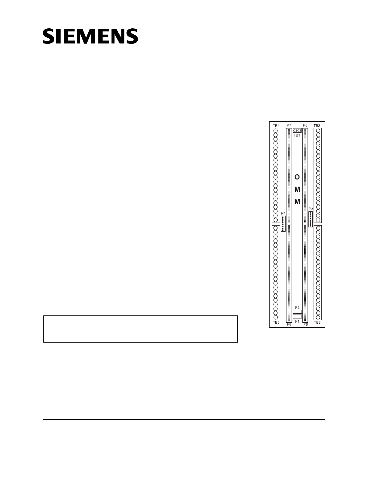
Figure 1
OMM-1 Module
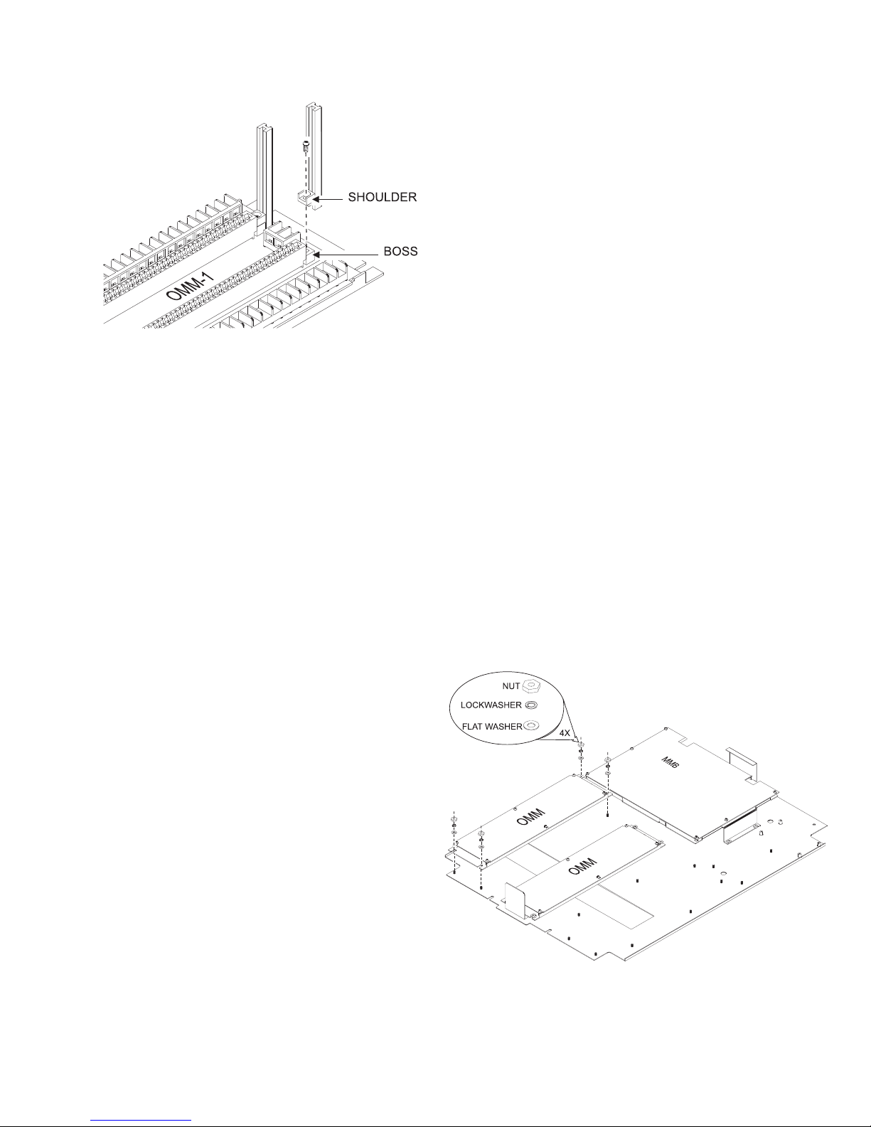
Figure 2
Installing the Card Guides
To install the card guides:
(Refer to Figure 2)
2. Place the module on the mounting studs in
the left-hand position of the enclosure as
shown in Figure 3.
3. Fasten the OMM-1 in position with the
No.10 nuts and washers provided.
4. To mount any other OMM-1 modules
used in the system, repeat the above
steps. Use the center or right-hand
position for the additional modules as
needed.
5. When mounting OMM-1 modules in an
MLE-6 enclosure, it may be necessary to
reverse the mounting in the lower row by
placing the two position terminal block
TB1 at the bottom instead of the top
(Refer to Figure 5). This will insure that
the 14-conductor cables that are supplied
can be assembled.
1. Place the card guide shoulder on the
raised boss at the end of the card edge
connector.
2. Align the hole in the shoulder with the hole
in the boss.
3. Place the mounting screw in the hole in
the shoulder and tighten the screw.
4. Repeat Steps 1, 2, and 3 for the
remaining card guides.
To mount the OMM-1 card cage:
The OMM-1 mounts vertically in the enclosure
under the MMB or the PSR as shown in
Figure 3.
The installation kit for the OMM-1 includes the
following:
• Four No.10 nuts
• Four washers
• One 8 conductor ribbon cable
(P/N 555-190967)
• One 14 conductor ribbon cable
(P/N 555-192155)
To assign plug-in cards to the OMM-1:
The cards that can be assigned to plug into
the OMM-1 are the OCC-1, the ASC-1/-2, the
PLC-4, the RCM-1, the ZAC-30, and the ZC
zone cards. Determine which optional plug-in
cards are used in your CSG-M configuration.
Assign the plug-in cards to the card edge
connectors on the
OMM-1(s) as needed.
1. Hold the OMM-1 so that the two position
terminal block TB1 is at the top. (See
Figure 1.)
Figure 3
Mounting the OMM-1 Board
2
 Loading...