

Page 1

Instruction Manual November 2005
open channel
OCM III
Page 2

Safety Guidelines: Warning notices must be observed to ensure personal safety as well as that of
others, and to protect the product and the connected equipment. These warning notices are
accompanied by a clarification of the level of caution to be observed.
Qualified Personnel: This device/system may only be set up and operated in conjunction with this
manual. Qualified personnel are only authorized to install and operate this equipment in accordance with
established safety practices and standards.
Unit Repair and Excluded Liability:
• The user is responsible for all changes and repairs made to the device by the user or the user’s
agent.
• All new components are to be provided by Siemens Milltronics Process Instruments Inc.
• Restrict repair to faulty components only.
• Do not reuse faulty components.
Warning: This product can only function properly and safely if it is correctly transported, stored,
installed, set up, operated, and maintained.
Note: Always use product in accordance with specifications.
Copyright Siemens Milltronics Process
Disclaimer of Liability
Instruments Inc. 2005. All Rights Reserved
This document is available in bound version and in
electronic version. We encourage users to purchase
authorized bound manuals, or to view electronic versions
as designed and authored by Siemens Milltronics Process
Instruments Inc. Siemens Milltronics Process Instruments
Inc. will not be responsible for the contents of partial or
whole reproductions of either bound or electronic
versions.
While we have verified the contents of this
manual for agreement with the
instrumentation described, variations
remain possible. Thus we cannot
guarantee full agreement. The contents of
this manual are regularly reviewed and
corrections are included in subsequent
editions. We welcome all suggestions for
improvement.
Technical data subject to change.
MILLTRONICS®is a registered trademark of Siemens Milltronics Process Instruments Inc.
Contact SMPI Technical Publications at the following address:
Technical Publications
Siemens Milltronics Process Instruments Inc.
1954 Technology Drive, P.O. Box 4225
Peterborough, Ontario, Canada, K9J 7B1
Email: techpubs.smpi@siemens.com
• For a selection of Siemens Milltronics level measurement manuals, go to:
www. siemens.com/processautomation. Under Process Instrumentation, select
Measurement
• For a selection of Siemens Milltronics weighing manuals, go to:
www. siemens.com/processautomation. Under Weighing Technology, select
Weighing Systems
and then go to the manual archive listed under the product family.
and then go to the manual archive listed under the product family.
Level
Continuous
© Siemens Milltronics Process Instruments Inc. 2005
Page 3

TABLE OF CONTENTS
TITLE PAGE
ABOUT THIS ...
About This Ma nual 7
About the OC M-3 7
SPECIFICATIONS 9
Programmer 10
Transducer 11
Temperature Sensor 11
Cabling 11
Communication Softwa re 11
INSTALLATI ON
Installing the OCM-3 13
Outline and Mounting 13
OCM- 3 Layout 14
System Diagram 15
Installing the Transducer 16
Installing the Temperature Sensor 16
mA Output 17
Relays 17
Synchronization 18
Power Conne ctions 19
Installing the Memory Back-up Ba ttery 20
Communicating Via Compute r 20
Installing the Programmer 20
7ML19985AB01 OCM III 3
Page 4

START UP
General 21
Keypad 21
Legend 22
Initial Start Up 22
Fundamenta l Checks 25
OPERATION
Memory 27
Security 27
Units 27
Flow Calculation 28
Display 28
Damping 29
Relays 30
mA Output 30
Fail-Safe 31
Flow rate a nd Totaliz ing 31
Logging 3 2
Blanking 34
Temperature 34
Time and Date 34
Emulation Mode 35
Reset 35
Flow Velocity I nput 36
Auxiliary Head Input 36
DC Output 37
Diagnostic Aids 37
7ML19985AB01 OCM III 4
Page 5

‘D’ PARAMETER LISTING 39
‘F’ P ARAME TER LIST ING 41
‘P’ PARAMETER LISTING 43
‘U’ PARAMETERS FOR P3 PRIMARY ELEMENT 51
Simple Exponential Device s, P3 = 0 53
BS-3680 Rectangular Flume, P3 = 1 58
BS-3680 Round Nose Horizonta l Crest Weir, P3 = 2 60
BS-3680 Trapezoidal Flume, P3 = 3 62
BS-3680 U - Flume, P3 = 4 64
BS-3680 Finite Crest Weir, P3 = 5 66
BS-3680 Thin Plate Rectangular Weir, P 3 = 6 68
BS-3680 Thin Plate V-Notch Weir, P3 = 7 70
Rectangula r Weir (Contra cted), P3 = 8 72
Round Pipe, P3 = 9 74
Palmer-Bowlus Flume, P3 = 10 76
H - Flume, P3 = 11 78
Universal Head vs. Flow, P3 =12 80
Rectangula r Area x Velocity, P3 = 13 82
Trapezoidal Area x Velocity, P3 =14 84
Modified Trapezoidal Area x Velocity, P3 = 15 86
U Channel Area x Velocity, P3 = 16 88
Circular Area x Velocity, P3 = 17 90
Gull-Wing Area x Velocity, P3 = 18 92
Egg-Shaped Area x Velocity, P3 =19 94
Universal Area x Velocity, P3 = 20 96
APPENDICES
Maintenance 99
Error Codes 100
Communications 101
7ML19985AB01 OCM III 5
Page 6

7ML19985AB01 OCM III 6
Page 7

ABOUT THIS ...
ABOUT THIS MANUAL
Although the OCM-3 is very ‘approacha ble’ due its dialogue capa bilities and intuitive
operation, the user should be familiar with this manua l. This manual provide s the user
with the ne cessary information require d to install, sta rt up and operate the OCM-3.
As the OCM -3 prompts the user with spe cific message s in a step-by-ste p fashion
during programming, the Start Up section serves essentially to complime nt the
OCM- 3. Start Up provides the use r with instructions on the use of the programme r
and a n overview of the programming requirements.
The ‘D’, ‘F’, ‘P’ and ‘U’ para meters listed in the Paramete rs section provide a quick
refe rence of the available programming and display parame ters and the ir options. The
‘U’ parameter listing also provides mathema tical and graphical details as a reference
to assist the user in programming the OCM-3 to the primary element being used. The
user is urge d to rely on the ma nufacturer’s specification for obta ining and identifying
the primary element to which the OCM-3 is being applied.
In short,
If you want to know about
the product About This . . .
getting started Installa tion
how it works Opera tion
Read
Spe cifications
Start Up
Parame ters
Appendices
ABOUT THE OCM-3
The OCM-3 is to be used only in the manner
outlined in this instruction manual.
The Milltronics OCM-3 , Open Channel Meter, is an electronic instrument designed to
measure flow in open channels. I t is housed in a polycarbonate e nclosure and comes
with a removable programmer. As a system, it is used in conjunction with a re mote
ultrasonic transducer (or auxiliary head measurement device) and a temperature
sensor.
The OCM-3 transmits a pulse signal to the transducer which is then emitted as
ultrasonic pulses. The pulses echo off the water surface and are then sensed by the
transducer. The time for a pulse to echo back from the water surface is temperature
compensated and converted into a measurement of head.
7ML19985AB01 OCM III 7
Page 8

The OCM-3 converts the head measurement into flow rate, but also provides a
velocity sensor input for applications whe re a flow ve locity measurement is re quired to
perform the flow calculation. The flow rate is totalized and stored in a comprehensive
data log to provide deta iled flow analysis.
Programming of the OCM- 3 allows the opera tor to se lect the flow ca lculation specific
to the prima ry measuring device ( flume, we ir or pipe). Spe cial e mphasis has be en
placed on providing the most accurate flow calculations possible. To this end, specific
routines have been writte n to comply with the British Standards Institute’s
Specifications BS-3680. These routines calculate correction factors taking into
account se cond order effe cts such as approa ch velocity and bounda ry layer. In the
event that flow measurement is not covered by one of the flow calculations provided,
the O CM-3 ca n be programme d for flow measure ment using one of the universal
flow calculations.
The OCM-3 provides serial communication for re mote programming, data log re trieval
and print out for devices such as computers, PLC s and printers. Milltronics provides a
standa rd utilities softwa re package for OCM -3 programming, re mote display and data
retrieval. Howeve r, the use r is not limited to the software provided. T he user ca n
develop his own softwa re program to pe rform ta sks suited to his specific nee ds.
The OCM-3 features:
✓ multi field illuminated LC D, for ‘Flow and Tota l’ and ‘Relay Status’ display
✓ 0 or 4 to 20 mA output
✓ three multipurpose rela ys, including remote totaliza tion
✓ 1 to 2 4 months data log, subject to logging ra te
✓ extensive se rial communication, including RS-2 32
✓ removable infra-red programme r
✓ AC and D C (bi-current) opera tion.
7ML19985AB01 OCM III 8
Page 9

SPECIFICATIONS
Power: » dc supply: » 9 to 30 V D C, 8 W max
» ac supply: » 100/115/200/230 V ac ± 15%, 50/60 Hz,
20 VA max
Environmental: » location » indoor /outdoor
» altitude: » 2000 m max
» ambient temperature » – 20 to 50 °C (–5 to 122 °F)
» relative humidity » suitable for outdoor (Type 4X/Nema 4X
» installation category » II
» pollution degree » 4
Memory
back-up: » 3 V lithium battery (NEDA 5003LC or equivalent)
» operating life 1 year
» ‘SuperC ap’ capacitor for back-up
during battery replace ment
Range: » 0.3 m min to 1.2 m max ( 1 to 4 ft)
0.6 m min to 3 m max (2 to 10 ft)
Resolution: » 0.2 mm (0.007")
and / or
IP65 enclosure)
Accuracy: » ±1 mm/m, calculated error less than 0.02%
Temperature
Compensation: » external sensor to compensate over
Programming: » via supplied progra mmer and
Inputs: » velocity sensor and
Outputs: » transducer drive: » 44 Khz, 400 Vpp pulses of 0.1 msec typical
7ML19985AB01 OCM III 9
the ope rating range
communication link
auxiliary head » range: » 0 to 10 V dc
» resolution: » 2.7 mV
duration at a 100 msec typical repetition rate.
» instrumentation: » range: 0-20 or 4-20 mA
» resolution: 5 uA
» maximum loading: 1 KΩ
Page 10

» isolation: 300 V ac continuous
» relays: » 3 alarm/control relays
» 1 form ’C’ SPDT contact per relay, ra ted at
5 A at 250 V ac non-inductive or 3 0 V dc
» dc output: » +24 V dc
» 20 mA average to 200 mA at 1/10 duty
cycle max
Communication: » RS-232 or ± 20 mA bipolar current loop,300,
600, 1200, 2400, 4800, 9600 or 19200 baud
Data Logs: » va riable rate on 1 , 5, 15, 30 or 6 0 min or 24 hr
» 31 days minimum/2 years maximum
Display: » illuminated liquid crystal 5 x 7 dot matrix
display with 2 lines of 40 characters each
Enclosure: »Type 4X / NEMA 4X / IP65
» 209 mm W x 285 mm H x 92 mm D
(8.2" W x 11.2" H x 3.6" D)
» polycarbonate
Weight: » 2.3 Kg (5.1 lb)
Approvals: » CE *, F M, C SA
NRTL/C
» MCERT S C lass 1 open channel flow device with environment
operation limits at 35 °C (95 °F) at 93% relative humidity
SIRA MC 050058/01
PROGRAMMER
Enclosure: » genera l purpose
» 67 mm W x 100 mm H x 25 mm D
(2.6 " W x 4" H x 1" D)
» ABS plastic
Operating Temperature: » –20 to 50 °C (–5 to 122 °F)
7ML19985AB01 OCM III 10
Page 11

Battery: » 9 V (ANSI / NEDA 1604, PP3 or equivalent) or
3V lithium battery
TRANSDUCER
Model: » XRS-5*
Refer to associated Transducer manual.
TEMPERATURE SENSOR
Model: » TS-2 , LTS-1 or LTS-1C
Refer to associated Temperature Sensor manual.
CABLING
Transducer: » RG-62U coaxial
» maximum separation 183 m (600 ft)
» must be run in grounded meta l conduit
mA Output: » Belden 8760 or equivalent
Synchronisation: » Belden 8760
Temperature Sensor: » Belden 8760, 1 pair shielded/twisted,
Communication: » RS-232: » Belden 8770, 3 wire shielded, 24 AWG
» Bipolar Current: » Belden 9552, 2 pair shielded/twisted,
*Note: The XRS-5 must be used with the TS-2 external temperature sensor when
operating with the OC M- 3.
Velocity Input: » Belden 8760 or equivalent
7ML19985AB01 OCM III 11
18 AWG or equivalent
» maximum separation 183 m (600 ft)
» can be run in conduit with transduce r cable
or equivalent
» maximum separation 15 m (50 ft)
18 AWG or equivalent
» maximum separation 1,500 m (5,000 ft)
Page 12

Auxiliary Input: » Belde n 8760 or equivalent
24 V Output: » Belden 8760
COMMUNICATION SOFTWARE
Milltronics Utilities Software on standard P C floppy disk for DO S 3 .1 a nd up.
7ML19985AB01 OCM III 12
Page 13
INSTALLATION
Installation shall only be performed by qualified personnel
and in accordance with local governing regulations.
INSTALLING THE OCM-3
The OC M-3 should be mounted in a clean, dry are a that is: within the ambient
temperature range a nd suitable for the specified enclosure. The front cover should be
accessible for programming and viewing.
It is advisable to keep the OCM-3 away from high voltage or current runs, contactors
and SCR control drives.
Do not mount the OCM-3 in direct sunlight without the use of a sun shield.
This product is susceptible to electrostatic shock.
Follow proper grounding procedures.
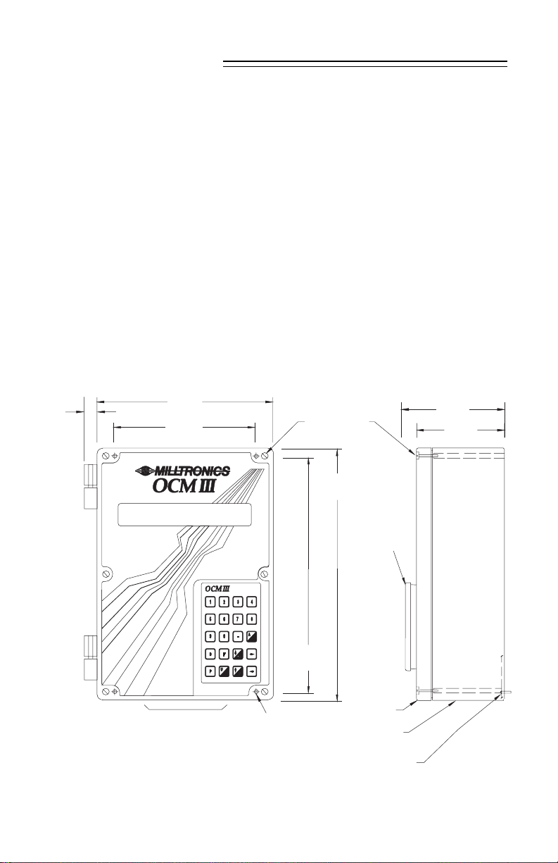
OUTLINE AND MOUNTING
209 mm
16 mm
(0.6")
Milltronics reccomends using a punch for making
holes in enclosure. Use suita ble cable glands to
maintain ingre ss rating.
(8.2")
172 mm
(6.8")
suitable loca tion for
conduit entrances
lid screws
(6 places)
267 mm
(10.5")
mounting holes
(acce ssed under
lid 4.3 mm (0.17")
dia.,4 place s
285 mm
(11.2")
progra mmer
enclosure
customer mounting
screw
lid
106 mm
(4.2")
91 mm
Non metallic enclosure does not provide grounding between connections.
Use grounding type bushings and jumpers.
(3.6")
13 OCM III 7ML19985AB01
Page 14
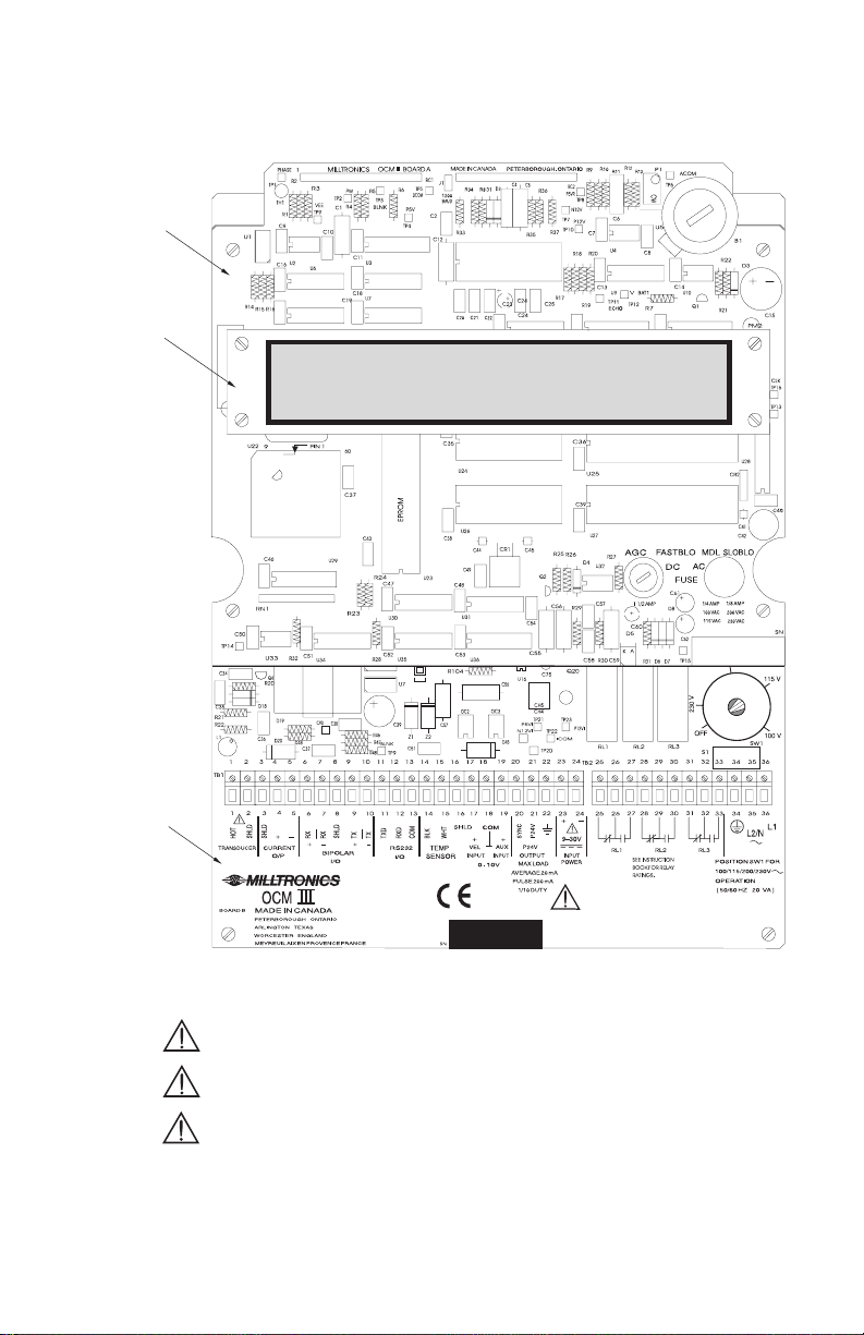
OCM-3 LAYOUT
board A
display
board
board B
All field wiring must have insulation suitable for at least 250 V.
Hazardous voltage present on transducer terminals during operation.
dc terminals shall be supplied from SELV source in accordance
with IEC 1010-1 Annex H.
Relay contact terminals are for use with equipment having no accessible
live parts and wiring having insulation suitable for at least 250 V.
The maximum allowable working voltage between
adjacent relay contacts shall be 250 V.
14 OCM III 7ML19985AB01
Page 15
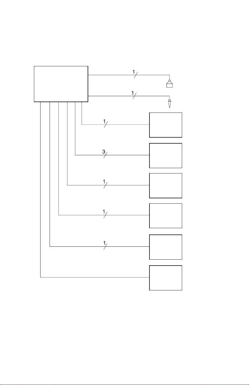
SYSTEM DIAGRAM
OCM-3
mA output
relay output
auxiliary input
velocity input
RS-232
Milltronics transducer,
see Specifications
Milltronics TS-2 ,
temperature sensor
customer device
customer alarm,
pump or control
device
customer device
customer device
customer device
bi-polar curre nt
(Milltronics communication)
Maximum system capa bility. Not a ll components or their maximum qua ntity
may be required.
15 OCM III 7ML19985AB01
Milltronics CVCC
98/03/05
Page 16
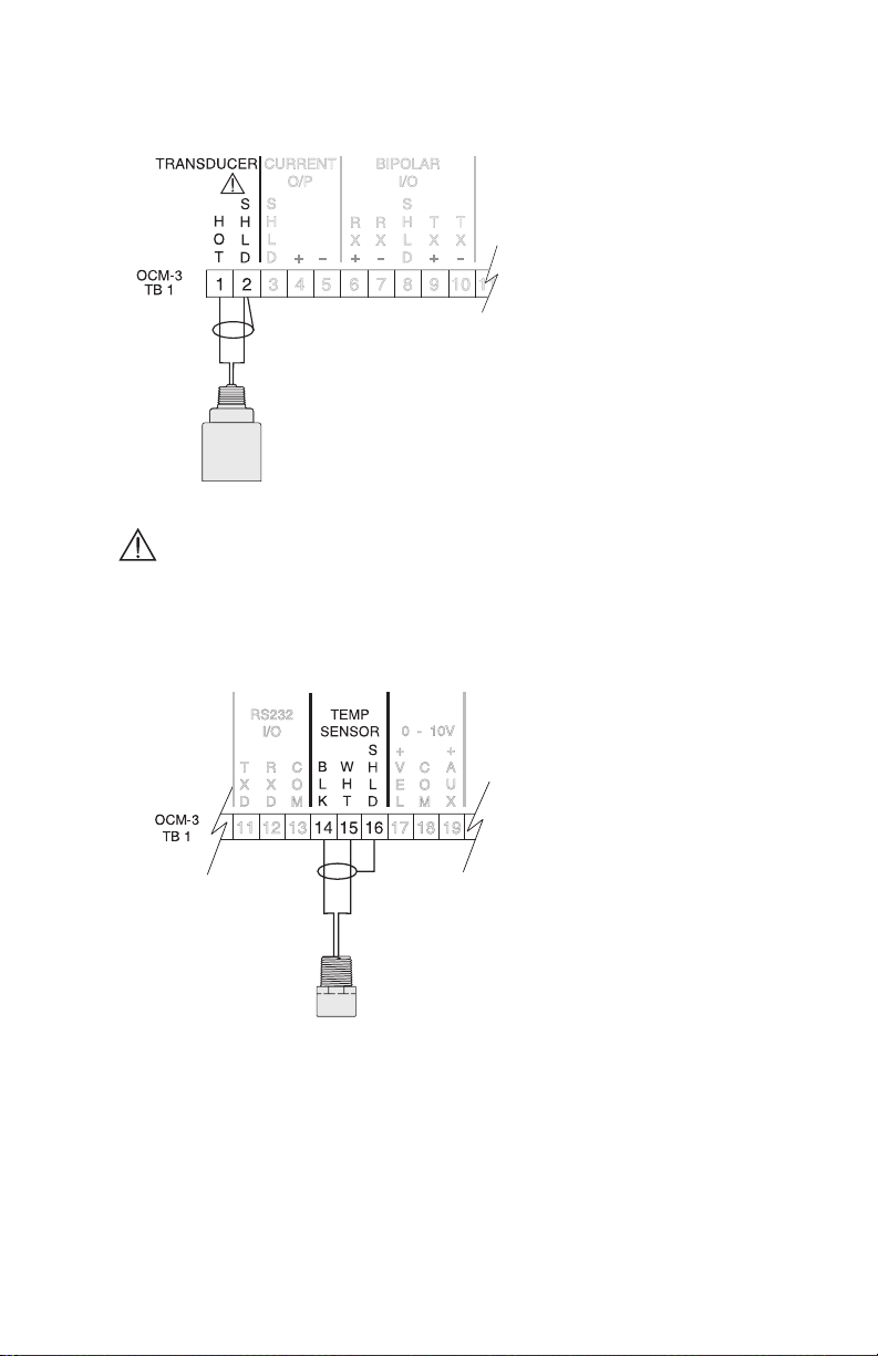
INSTALLING THE TRANSDUCER
Max cable run 183 m (600 ft) of
RG-62U or equiva lent. Cable must
be run in a grounded metal conduit
with no other cabling (except
Temp. Sensor ca ble).
Ground shield at O CM-3 only.
Insulate shie ld at junctions to
prevent inadvertent grounding.
Basic Wiring – T ransducer
Hazardous voltage present on transducer terminals during operation.
Note: When using the XRS-5 transducer with the OCM-3, use the TS-2 external
temperature sensor. The internal temperature sensor in the XRS-5 cannot be used.
INSTALLING THE TEMPERATURE SENSOR
In order to compensa te for uniform
temperature change in the air
between the transducer and the flow
surface, the temperature sensor
must be connected to the OC M-3.
Maximum cable run 183 m (600 ft) of
Beldon 8760, 1 pair shielded/twisted,
18 AWG or equivalent.
Tempera ture sensor cable ca n be
run with the transducer cable in a
grounded metal conduit.
Ground shield at OCM-3 only.
Basic Wiring – Temperature Sensor
16 OCM III 7ML19985AB01
Page 17
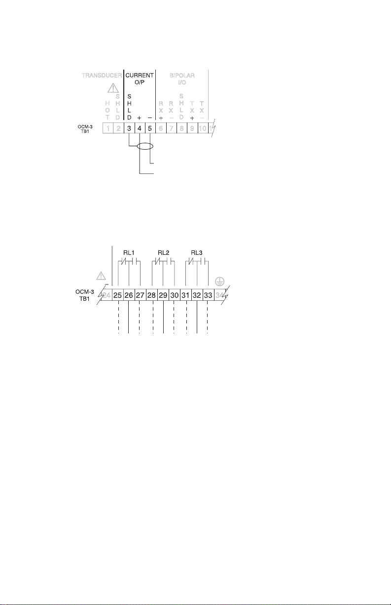
mA OUTPUT
RELAYS
isolated 0 or 4 to 20 mA output (P26) into 1 KΩ load maximum.
Wiring should conform to standard instrumentation practice s.
Ground shield at OCM-3 only.
relays shown in de- energized state ,
contacts rated at 5 A at 250 V
non-ind uctive.
n.c. com n.o. n.c. com n.o. n.c. com n.o.
All relays are certifie d for use in equipment whe re the short circuit capacity of the
circuits in which they are connected is limited by fuses ha ving ratings not exce eding
the rating of the re lays.
17 OCM III 7ML19985AB01
Page 18
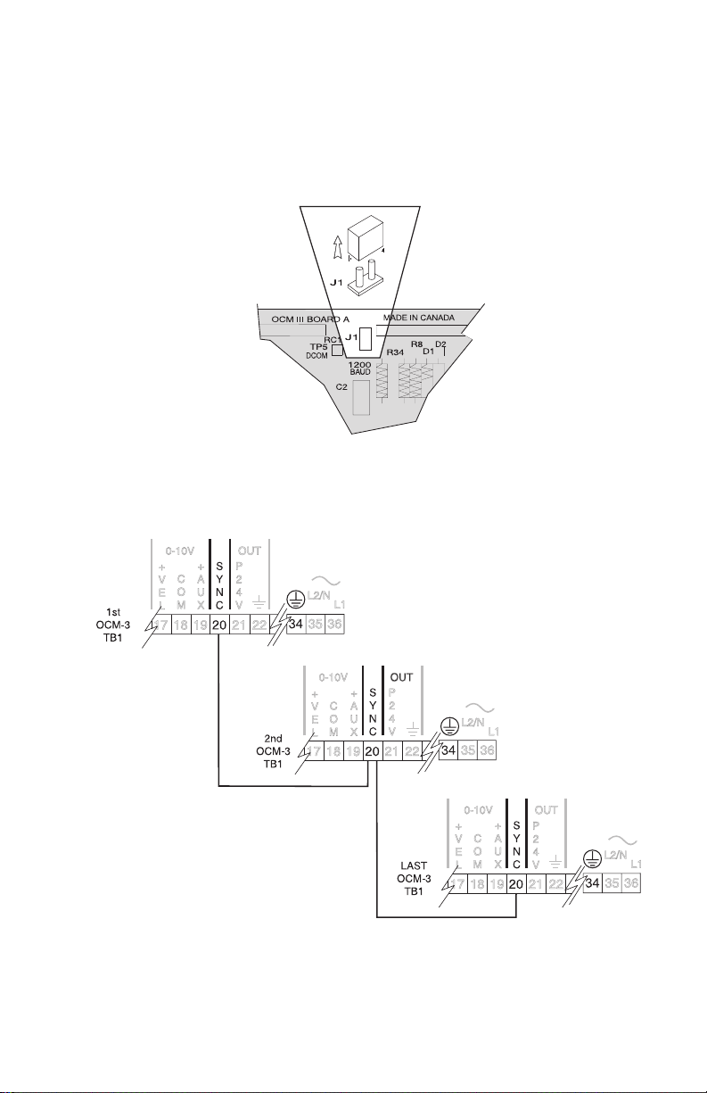
SYNCHRONIZATION
Where two to a maximum of twelve transducers will be sharing a common conduit the
OCM- 3s should be synchronize d. In order to synchronize OCM-3s:
» remove jumpe r J1 on board A on all but one OCM-3
» interconnect the SYNC terminal (T B1-20) of all OC M-3s. I nsure that
all O CM-3s sha re a common ground ( TB1-34 ).
18 OCM III 7ML19985AB01
Page 19
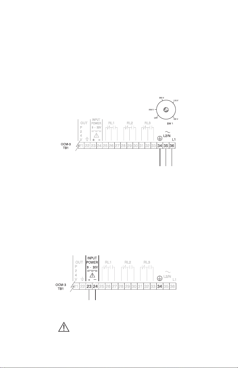
POWER CONNECTIONS
The OCM-3 power supply accepts 100, 115, 200 or 230 V ac per switch SW1
(board B) se lection and 9 to 30 V dc.
The OC M- 3 operates e ither under ac or dc power, or both ac and dc live
simultaneously. If both ac and dc power are live, the OC M-3 normally draws power
from the ac supply. In the e vent tha t the ac supply fails, the OCM- 3 then draws power
from the dc supply.
AC POWER
*
* switch shown in
‘OFF ’ position,
select appropriate
voltage.
100/115/200/230 V ac, 50/60 Hz,
select volta ge via switch on board B
The equipment must be protected by a 15 A fuse or
circuit breaker in the building installation.
A circuit breaker or switch in the building installation, marked
as the disconnect switch, shall be in close proximity to
the equipment and within easy reach of the operator.
DC POWER
nega tive dc input ( TB1- 24 ) is
9 to 30 Volt
dc input
dc terminals shall be supplied from SELV source in accordance
with IEC 1010-1 Annex H.
19 OCM III 7ML19985AB01
tied to ground (TB1-3 4)
Page 20
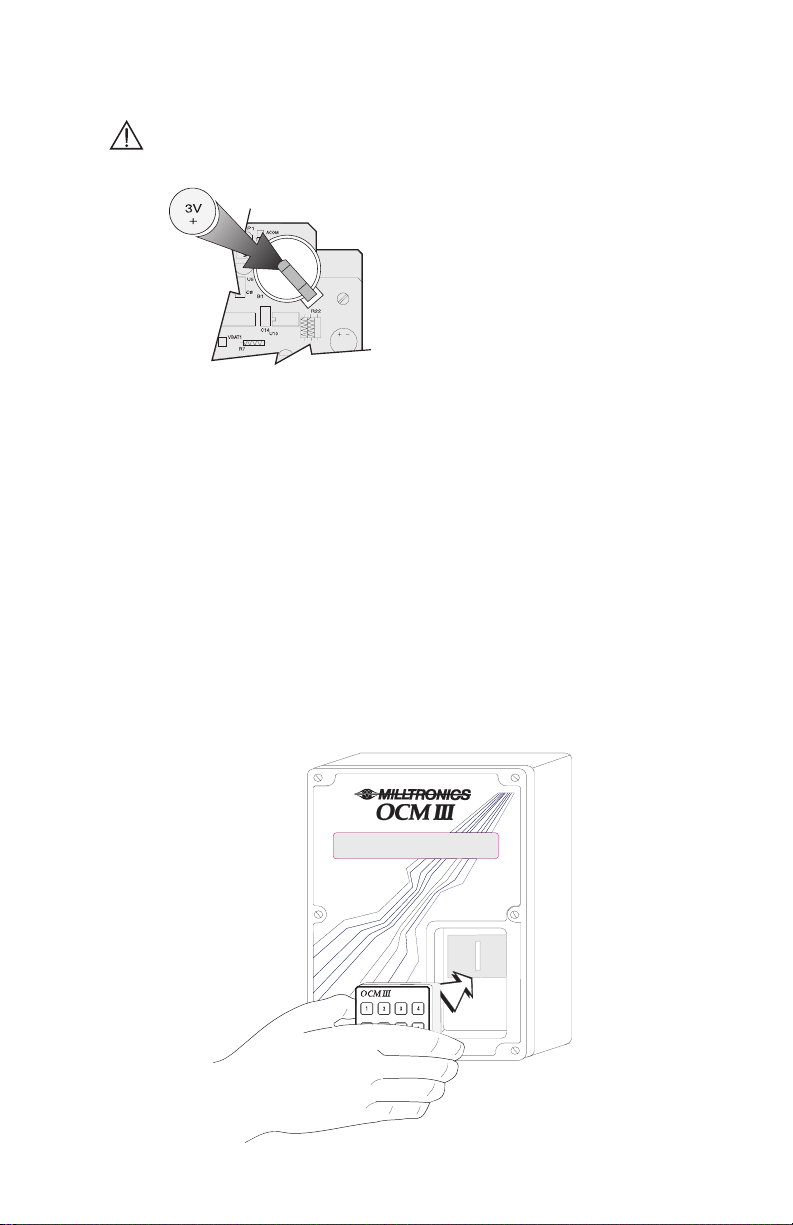
INSTALLING THE MEMORY BACK-UP BATTERY
Disconnect power before installing or replacing the ba ttery.
Do not install the memory back- up
battery until the OCM -3 is to be used.
The unit is supplied with one battery
package. Remove the battery from
the pa ckage and insert it into the
batte ry socket.
Refer to Operation \ M emory.
The memory battery, B1 (see Specifications) should be replaced yea rly to insure
memory back up during lengthy power outages. An on board capacitor provides
one hour of memory retention in order to preserve the me mory while the battery
is being changed.
COMMUNICATING VIA COMPUTER
Refer to Communication.
INSTALLING THE PROGRAMMER
To program the OCM-3 via the Programmer, it must be placed into the front cover
recess of the OCM -3. The back of the Programmer has a magne tic plate which will
hold the progra mmer in place. I t ca n be removed when programming is completed.
20 OCM III 7ML19985AB01
Page 21
START UP
GENERAL
For the initial start up, it is advisable to use the programmer for programming the
OCM-3. The programmer transmits a coded infrared signal each time a key is pressed.
The OCM- 3 is designed to a utomatically scroll through the ‘A’, ‘D’, ‘F’, ‘P’ and ‘U’
paramete rs in a structured sequence. The scrolling is interactive in that, depe nding on
the option chosen for a given para meter, subseque nt parameters may be skipped or
modified. The user is thus prompted to satisfy only the pa rameters which are availa ble
to him for the application he ha s chosen.
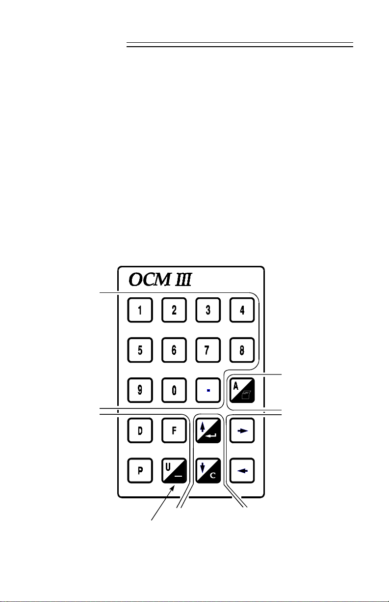
KEYPAD
numeric
entries with
decimal point
access to ‘A’ parame ters
/ initiate s a printout while
viewing ‘Flow and Total’
access to ‘D’, ‘F ’,
‘P’ and ‘U’
paramete rs
negative
scrolls
Forward
Backward
through
through the
the parame ters / ente rs
content of entry field
scrolls
parameters / clears content of entry field
scrolls through selecte d
parameter options
7ML19985AB01 OCM III 21
Page 22
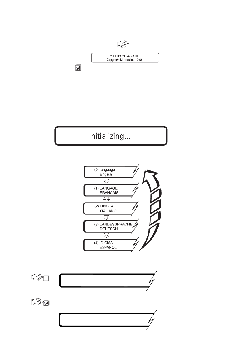
LEGEND
Press the a ssociated progra mmer key:
Display shown on OCM- 3:
Programmer key:
INITIAL START UP
After installation procedures ha ve been completed, the OC M- 3 may be powered up.
Upon initial powering up, the unit momentarily displays:
and the n scrolls through the ava ilable languages:
The OC M- 3 is asking which langua ge you prefer to communicate in!
0
(0) la nguage
English
English language
selecte d
advance to ‘F0’
F0 enter security code
< - - -
7ML19985AB01 OCM III 22
Page 23
8 2 8
1
72
factory set security code
2.71828 must be entered
P0 language
0 English
if the wrong language
was selected, it may
be changed here
P1 dimensional units
0centimeters
continue programming by
entering the desired options
and advancing until the
scroll returns to ‘P0’. It is
then assumed that the
user has entered all the
required paramete rs.
P0 language
0 English
For optimum calibration accuracy, an ‘F13’ should be performed prior to acce ssing
‘F2’, the normal operating mode.
3
1
F13 auto zero calibration
enter the current head. The
OCM-3 calculates ‘P46’ and
automatically ente rs the va lue.
e.g. 1 6 0
01 6
F13 auto zero calibration
160
F13 auto zero calibration
0 completed
7ML19985AB01 OCM III 23
Page 24
If data logging is desired, the time and date must be set.
4
F4 24-hr. time
e.g. 1141
4
1
1
1
F4 24-hr. time
1141
11: 41 a.m.
seconds are always
assumed to be 00
,
F4 24-hr. time
11:41:00 enter new time
time is displa yed in
hh:mm:ss
F5 (ddmmyyyy) date
e.g. 12101492 October 12, 1492
0 1
4
9 211 2
F5 (ddmmyyyy) date
12/10/1492 enter new date
The start up procedure is now complete. Enter ‘F2’ to place the OCM-3 in the normal
operating mode.
2
Note: To save parameter values, return to RUN mode (F2) after programming.
The OC M-3 now displays the flow ra te and total. Refer to Ope ration \ Display
7ML19985AB01 OCM III 24
Page 25

FUNDAMENTAL CHECKS
For accurate determination of flowrate, accurate head measurement is essential.
Check the following and correct if necessary.
» check D5 for correct temperature at transducer location.
» check D9 for corre ct distance from transducer to he ad.
» check D0 for accurate head measurement.
7ML19985AB01 OCM III 25
Page 26

7ML19985AB01 OCM III 26
Page 27

OPERATION
Upon powe r up, the transducer is fired pe riodically as se t by P36. A long interval
betwe en measureme nts may be de sirable in order to conserve power* whe n
operating the OCM- 3 from a D C source of limite d capacity.
The echo is processed to determine the head (D0). The flow rate (D1) is calculated by
the OCM-3 as a mathematical function (P3 and P4) of head or a function of head and
velocity (P42). The flow rate is then integrated to yield the totalized flow (D2). The
‘Flow’ and ‘Total’ fields which a re displayed during the norma l running mode (F2) are
also continuously updated.
Viewing or changing the content of a paramete r (except F1, e mulation) is done
without disturbing the acquisition, processing or logging of flow da ta (see \ Security).
*
restricted usage of display lighting (P14), relays (P15, 18 & 21), mA
output and communications will also conserve power.
MEMORY
During a power interruption, the memory back up will hold the programming, the log
and the totaliz er values, and run the clock. The memory battery (B1) provides up to
one ye ar of memory re tention (se e Appendices \ M aintena nce).
Note: To save parameter values, return to RUN mode (F2) after programming.
SECURITY
The content of all ‘A’, ‘D’, ‘F’, ‘P’ and ‘U’ parameters ca n be viewed without having to
satisfy the security parameter, F0. However if it is desired to change the content of
any of these pa ramete rs, the se curity para meter must be satisfied (exce pt for
resetting the running min/max displays, parameters D3/D 4 and D 6/D7).
Once security ha s been satisfied, access continue s for 5 minutes after the last key is
pressed or until F2 is re -entered.
The security code may be changed from its factory set value, 2.71828, by entering a
new value into F10. It is imperative that the new value be recorded, as the code can
not be vie wed. I f the code is lost, consult Milltronics.
UNITS
Programming of the OCM-3 involves setting the units of measure:
» P1 linear and velocity
» P2 temperature
» P5 flow rate and volume
If the units are change d during the course of opera tion, the change will be effected
through all a ssociated parameters and displa ys and will rescale flow and tota l data
stored in the logs.
7ML19985AB01 OCM III 27
Page 28

FLOW CALCULATION
Absolute vs. ratiometric
The OC M-3 can be progra mmed to use e ither of two methods (P4) for calculating flow
from the head measurement: absolute or ratiometric. The result is the same
regardless of the method use d. The principal difference is the information that must
be e ntered in orde r for the OC M-3 to carry out the calculation. T he user’s choice of
method may ultimately be based upon the information which is at hand. Re fer to U
parameters for the primary element selected for a listing of the information required.
For the ratiometric me thod, it is usually sufficient that the user know the flow rate
) which occurs at maximum he ad (h
(Q
cal
On the other hand, absolute calculations require that the user enter information such
as: the physical dimensions of the primary ele ment and the constant rela ting to units
of mea sure for both linear dimensions and flow ra tes.
).
cal
e.g.
the genera l formula for flow through a single exponent primary element is:
x
Q = KH
the specific formula for flow through a 45° V-notch we ir is:
cfs = 1.03H
2.5
thus: Q = flow in cubic feet pe r second
K = constant of 1.03
H = head in feet
The absolute method is not applicable to the following:
Palmer Bowlus flume
H flume
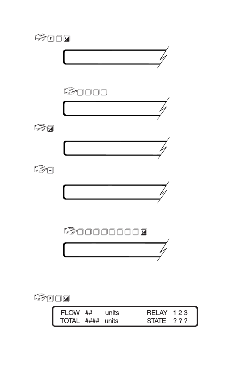
DISPLAY
The normal display during operation is the Flow and Total Display (F2).
flow rate fie ld
relay / "no echo" field
totalizer field
status field
7ML19985AB01 OCM III 28
Page 29
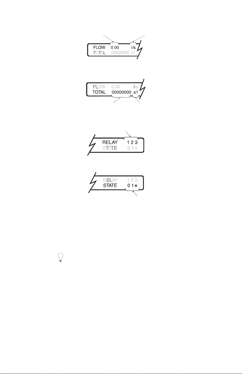
Flow Rate Field
Totalizer Field
flow rate
units, P5
total
multiplier, P3 2
Relay / No Echo Field
relay identification
under loss of echo
condition, "NO
ECHO" will
alternately flash
Status Field
relay sta tus : 0 = re lay de -e nergized
1 = relay energized
* = alarm state (indicated when
flashing)
The OCM- 3 provides illumination for the LCD for ea sier viewing of the display.
Illumination can be set (P 14) to be normally on or off, or a utomatic. When automatic is
selected, the lighting will automatica lly go on when ke ypad activity is sense d and the n
extinguish after 1 5 seconds of inactivity.
For battery operation, set display lighting to off or auto.
DAMPING
The OC M- 3 provides two separate da mping functions: rea ding and mA output. Ze ro
or no damping allows fastest re sponse while high or 100% provides the slowest
response. The damping is usually set to provide a re liable response without
sacrificing stability.
The rea ding damping, P13 , dampe ns only the flow rate reading of the ‘Flow and T otal’
display F2. The damping selections are: off, low, medium and high. Rela y functions
associated with flow rate respond to the dampened re ading values.
mA output damping, P27, da mpens the cha nge in the mA output. The parame ter entry
is in seconds for spanning the 0 to 100% of the mA range selected (P26). Displays
and relay functions a ssociated with the mA output respond to its
dampened value.
7ML19985AB01 OCM III 29
Page 30

RELAYS
Three on board multipurpose relays are provided by the OCM-3. P15, 18 and 21 set
the respective functions for relays 1, 2 and 3. D epending on the function selected,
these para meters de termine the need and configuration of the subsequent re lay
control parameters, P16, 17 (relay 1); P19, 20 (relay 2) and P22, 23 (relay 3).
If the relay is to function as a driver for a remote totalizer or as a flow sampler contact,
the totalizer multiplier (P32) will be factored by the setpoint . Note that paramete rs
P16, P19, and P22 will default to zero. When a relay is set to totalizer (P32), you must
have the applicable parameter (P16 for relay 1, P19 for relay 2, or P22 for relay 3) set
to something othe r than zero (normally 1).
Example: For relay 1
Re lay totalize r fa ctor =
The status of e ach relay is shown in the display. Re fer to \ Flow and Total Display.
totalizer factor (P32)
relay 1 setpoint (P16)
100 (P32=5)
=
2 (P16)
= 50 units/pulse
For battery opera tion, have relays energiz ing on alarm.
mA OUTPUT
The OC M-3 provides a mA output ( TB1 -4/5) which can be a ssigned (P24 ) to
represent the measurement of flow, head, velocity or temperature. The associated
scaling, P2 5, is fa ctory set to a value of ‘0’. This provides normal scaling with respect
to the assigned measurement.
Normal scaling for representation of flow, head or ve locity is:
» 0 or 4 mA = 0
*
» 20 mA = maximum measurement value for: » P6
at maximum head
» P7: maximum head
: flow rate
» P10: velocity
at maximum head
Normal scaling for representation of te mperature is:
» 0 or 4 mA = – 40 °C
» 20 mA = 60 °C
If custom scaling is required, the 20 mA corresponding va lue ( other than 0) can be
entered into P25. The range (0 to 20 or 4 to 20 mA) and damping (see Damping) are
set via P26 and P27 respectively.
7ML19985AB01 OCM III 30
Page 31

The mA function can be ove rridden for test purposes by se tting the desire d mA value
into F3. When the value is entered, the mA output will go to that value. When F3 is
exited, the mA output will revert to normal operation. Also, see \ Emulation Mode.
P6 is calculated by the OCM-3.
*In the case of absolute calculations (P4=0),
FAIL-SAFE
In the event of an echo loss, the fail- safe timer will begin counting. I f the echo loss
duration surpasses that of the time set (P29), a ‘
Status field (see \ D isplay) . The mA output will respond (P 30) by either holding the last
value or immedia tely going to a pre determine d value (P31) . The head and derive d flow
will hold their last value a nd totalization and logging will continue, based on that value.
Upon resumption of a valid echo, the mA output will re turn to a value corresponding to
the present value of the measurement assigned, at the mA damping rate (P27).
No Echo
’ alert will be displa yed in the
FLOW RATE AND TOTALIZING
Flow rate
Calculation of the flow rate is ongoing. It is normally viewed under the Flow and Total
display (F2 ) with the de cimal point set pe r P33. I t can also be viewed under D1 a s the
raw flow calculation. Da ta on the running minimum and ma ximum flows that ha ve
occurred since the last reset can be vie wed in two ways:
» F7 gives the running min/ma x flows and the ir time a nd date of occurrence since
the la st reset. F7 is reset by F8 but only a fter satisfying the security pa ramete r F0.
» D3/D 4 give the respective running min/max flow data, only, that have occurre d
since they were last reset. D3/D4 are reset simultaneously by entering 0 into
either D3 or D4. D3 and D4 will then adopt the current flow rate and track the
running min/max values from that point on. The security parame ter (F0) does
not need to be satisfied in order to reset D3 /D 4.
Flow data spe cific to a particular time and date ca n be viewed unde r the data log F14
(see \ Logging).
Totalizing
Totalizing of the calculate d flow is ongoing. It is norma lly viewed under the Flow and
Tota l display (F 2).
An auxiliary totalizer (D2 ) is provided for operator usage and is intende d for short term
totalizing to a maximum count of 999999. It can be reset or preset independently of
the F 2 totalizer after satisfying the security pa ramete r (F0 ).
In order to adjust the ra te of filling of the tota lize r, the totalize r multiplier (P32) can be
set to an appropriate value. The totalizer can be reset via F11. Totalizing that is
specific to the time and da te can be viewe d under the da ta log F1 4.
The OC M-3 can be programmed to operate a remote totalizer by a ssigning any of the
relays (P15, 18 or 21) to act as a totalizer contact*. Under this function, the maximum
rate of contact closure is 2/sec with a closure duration of 200 msec**.
The totalizer count is set by the relay setpoint parameter (P16, 19 or 22 respectively).
*
**
Typically the totalizer should be set for 300 to 3000 counts per day at maximum flow.
7ML19985AB01 OCM III 31
Page 32

Under low flow conditions, a cut- off head ( P45) can be ente red to avoid totalizing
flows occurring at or below the flow corresponding to the cut-off head.
LOGGING
The OC M- 3 provides an extensive logging feature which can be viewed on the local
display or retrieved via the serial communication link. T he logging rate (P 39) can be
fixed or va riable. The latter being useful in conserving logging space. The condition for
variable logging is determined when selecting the logging rate.
Variable logging rate conditions are ca tagorized as : rate of change of flow, percent of
maximum flow or percent of maximum head. Logging occurs at the normal (slower)
rate while the condition is less than the setpoint (P 40 ). If the condition excee ds the log
rapid setpoint, the ra pid rate of logging ta kes effe ct until the condition falls below the
log normal setpoint (P41).
The associa ted se tpoint units are : % cha nge of maximum flowrate per minute, % of
maximum flowrate a nd % of maximum hea d, respectively. The setpoints represent the
absolute value of the rate of change; that is, for either increasing or decreasing
flowrate . The OCM- 3 does not recognize negative e ntries into P-40 and P-4 1.
Flow data is logged in 1/2 % increments from 0 to 110 % of maximum flow. Flows
above 110 % are logged as 110 %. Truncation of flows to 110 % does not apply to
daily totalization.
Log Capacity vs Rates
rate capacity
1 min 31 days
5 3 months
15 9 months
30 1 year
60 1.5 years
24 hr 2 years
e.g. 15 / 5 9 months max / 3 months min
Once the log is filled, the old da ta will be successively written over with the new
data being logge d.
The log can be examined via F1 4. Viewing of the log is done by task a nd by method.
The viewing ta sks are: daily flow totals, flow rates and min-ma x flow data for flow or
temperature. The viewing me thods are : by first entry, by last entry and by specified
date . The scrolling keys are used to mane uver through the tasks, methods and
time of da y.
7ML19985AB01 OCM III 32
Page 33

Viewing the data log
The day totalizer (F14) does not use the master totalizer multiplier (P32). It is possible
that the da ily total overflows. I n such a case the display will show ++ +. ++.
7ML19985AB01 OCM III 33
Page 34

BLANKING
Blanking is used to ignore the zone in front of the transducer where ringing or other
false echo is at a level that interferes with the processing of the true echo. The
minimum blanking is factory set, but can be overridden by ente ring the de sired
distance into P47.
Ringing is the inherent na ture of the transducer mass to continue vibrating after the
transduce r has bee n fired. Ringing decays to a cceptable levels in the order of
milliseconds. Excessive cold or over tighte ning of the transduce r mounting may
increa se the ring time such that it appea rs as an e cho during the receive cycle. This is
usually indicated by an incorrect high head re ading. Excessive ring time may be
overcome by increasing the blanking.
TEMPERATURE
The temperature a s currently registe red by the temperature sensor is viewe d under
D5. D ata on the running minimum and maximum temperatures that ha ve occurred
since the last reset can be viewe d in severa l ways:
F7 gives the running min/max temperature s and their time and date of occurrence
since the last reset. F7 is re set by F8 but only a fter satisfying the se curity
parameter F0.
D6/D7 give the respective running min/max te mperature data, only, that ha ve
occurred since they we re last reset. D6 is reset by entering a value lower than D 5,
and D 7 is reset by entering a value larger tha n D5. D6 and D7 will then adopt the
current te mperature value and track the min/max va lues from that point on. The
security parameter F0 does not need to be satisfied in order to reset D6 or D7.
Tempera ture data specific to the time and date can be viewed unde r the data log F14
(see \ Logging).
D14 indica tes the resistance of the temperature sensor corre sponding to the
temperature shown in D5.
TIME AND DATE
If the data logging fea tures of the OC M-3 are to be used, the time (F4 ) and date (F5)
must be set. The day starts at 00:00:00 and ends at 23:59:59.
Adjusting the Time
If the clock time is advance d beyond the next anticipated logging time, the entry for
each missed logging time is filled with a code which indica tes that the system was not
able to make entries at those times.
The daily total will be reduced proportional to the amount of time the day
was shortened.
If the clock time is set back beyond the pre ceding logging time, the previously logged
date will be written ove r with new data as the logging proceeds.
7ML19985AB01 OCM III 34
Page 35

The daily total will be increased proportional to the amount of time the day was
lengthened.
Adjusting the Date
If the calenda r is reset, the OCM-3 will adjust the log date s accordingly, ta king into
account le ap years and days per month.
EMULATION MODE
The flow calculation (P3/P 4) can be checked for accura cy by using the e mulation
paramete r F1 . The head is entered a nd the corresponding flow is displayed. This
function is useful whe n troubleshooting discrepancies be tween the OCM-3 calculation
and the expected flow.
Relays a ssigned to functions associa ted with the emulation para meter re spond to the
emulated flows.
The mA output does not track the emulated flows whe n P2 8 (mA output emulation) =
0. Howe ver, if it is required to do so, then the e mulator pa rameter should be set to 1.
RESET
The following rese ts can only be executed after satisfying the se curity access, F0 .
Cold Start
If it is de sired to rese t all para meters, logs and totalizers to their fa ctory setting, this is
done by forcing a cold start, F12.
Master Totalizer
If it is de sired to rese t the maste r totalize r (F2), this is done by para meter F 11.
Data Log
If it is de sired to rese t the data log (F14) , this is done by pa rameter F15.
Min/Max Log
If it is de sired to rese t the min/ma x log (F7 ), this is done by parameter F8.
7ML19985AB01 OCM III 35
Page 36

FLOW VELOCITY INPUT
In some applications, the flow calculation for the chosen primary element requires a
velocity input. In this type of application, the transducer measureme nt is used to
calculate the cross sectional area of the flow. By multiplying the area with the distance
per time units of velocity, the volume per time units of flow are calculated. The
calculated velocity ca n be viewed via D8 .
The 0% and 100% limits of the velocity input must be scaled using parameters
P8 and P9.
» se lect P8
» enter the voltage corresponding to z ero velocity
» se lect P9
» enter the velocity corresponding to 5 V
e. g. If the velocity sensor output is 1 V per m/ sec and the output is
scaled for 7 V at 100% velocity (7 m/sec), then enter 5 m/sec. If the
output is scaled for 4 V at 100% velocity (4 m/sec), enter 5 m/sec.
P8 and P9 can only be accesse d if P3 has been set for an option that requires the use
of a velocity input. The input voltage level can be viewed via D12.
Voltage Input
typical 1 - 5 V signal from
velocity sensor.
Signal must be positive with respect to ground.
Velocity Input
typical 4 - 20 mA signal from velocity sensor.
Add termina ting resistor.
e.g. 250 Ω for 1 - 5 V over 4 - 20 mA.
(additional to Basic Wiring)
Current Input
AUXILIARY HEAD INPUT
In some applications, the transducer input (T B1- 1/2 ) is not used to provide a signal for
head measureme nt. A typical exa mple of this is an application which is beyond the 3
m (10 ft) range of the OCM-3. In such a case, the he ad could be derive d from anothe r
Milltronics level monitor or other compa tible device.
The method of hea d determination is set by P42. The OCM -3 simply substitutes the
signal from the auxiliary device for the ultrasonic me asurement provided by the
transduce r. T he programming and consequent flow calculation are performed
as normal.
7ML19985AB01 OCM III 36
Page 37

The 0% and 100% limits of the auxiliary input must be scaled using parameters P4 3
and P44.
» se lect P4 3
» enter the voltage corresponding to zero he ad
» se lect P4 4
» enter the head corresponding to 5 V.
e. g. if the he ad output is 1 V per m and the output is sca led for 7 V at
100% head (7 m), then enter 5 m. If the output is scaled for 4 V at
100% head (4 m), enter 5 m.
P43 and P44 can only be a ccessed if P42 has bee n set for head de termination by an
auxiliary device. The input voltage level can be viewed via D1 3.
Voltage Input
typical 1 - 5 V signal from
auxiliary de vice.
Signal must be positive with respect to ground.
Auxiliary Input
typical 4 - 20 mA signal from a uxiliary device .
Add termina ting resistor.
e.g. 250 Ω for 1 - 5 V over 4 - 20 mA.
(additional to Basic Wiring)
Current Input
DC OUTPUT
The OCM-3 provides a 24 V DC output that ca n be used to supply powe r to a remote
customer device. The output is not isolate d from the DC rails that supply the OCM -3
electronics and no overload protection is provide d. As such, the output must not
operate beyond its specified ca pacity.
DIAGNOSTIC AIDS
D15 through D 18 are diagnostic aids to Milltronics service personnel when
troubleshooting system problems.
D18 also serves a s a performa nce indicator by displaying the number of valid echos
received a s a perce ntage of the number of pulses be ing fired by the transducer. A low
value indicates that a large proportion of the pulses fired are not producing valid
echos. In such insta nces, the transducer should be checked for prope r mounting and
aiming or the transducer wiring checked for excessive noise. If the va lue is zero,
shorted or ope ned transduce r wiring may be suspe ct.
7ML19985AB01 OCM III 37
Page 38

‘D’ PARAMETER LISTING
Refer to ‘Operation’ for details.
D0 head
D1 flow rate
D2 short total *
D3 maximum flow rate
D4 minimum flow rate
D5 temperature
D6 maximum tempe rature
D7 minimum tempera ture
D8 velocity
D9 nominal target range
D10 analog milliamps
D11 internal DC volts
D12 velocity volts
✧
✧
D13 auxiliary input volts
D14 tempe rature sensor ohms
D15 self- test checksum
D16 restarts
D17 exceptions
D18 valid echos per 100
*
security access required
✧
applicable to flow calculations requiring velocity sensor
7ML19985AB01 OCM III 39
Page 39

7ML19985AB01 OCM III 40
Page 40

‘F’ PARAMETER LISTING
Refer to ‘Operation’ for details.
F0 e nter security code
F1 e mulation mode
F2 run mode
F3 ke ypad to mA output
F4 show time
set time
F5 show da te
set da te
F6 software identification number
F7 vie w min/max da ta
F8 re set min/max data
F9 se lf check
F10 change security code
F11 reset master totalizer
F12 force a cold sta rt
F13 auto zero calibration
*
*
*
*
*
*
*
*
*
*
F14 examine da ta log:
task: vie w daily totals
view flow rates
view min/ma x data
method:
first day
last day
specified day
F15 clear data log
*
*
security access required
7ML19985AB01 OCM III 41
Page 41

7ML19985AB01 OCM III 42
Page 42

‘P’ PARAMETER LISTING
Refer to ‘Operation’ for details.
P0 langua ge
0 = english
1 = french
2 = italian
3 = german
4 = spanish
P1 dimensiona l units
linear velocity
0 = centimetres centimetres per second
1 = inches inches per second
2 = feet feet per second
3 = metres metres per second
P2 temperature units
0 = Celcius
1 = Fa hrenheit
P3 primary element
0 = expone ntial device
1 = BS-3680 Rectangular Flume
2 = BS-3680 Round Nose Horizontal Crest Weir
3 = BS-3680 Trapezoidal Flume
4 = BS-3680 U-throated Flume
5 = BS-3680 Finite Crest Weir
6 = BS-3680 Thin Plate Rectangula r Weir
7 = BS-3680 Thin Plate V-notch Weir
8 = Re ctangular Weir ( contracted)
9 = Round Pipe
10 = Palmer Bowlus Flume
11 = H Flume
12 = Universal Head vs. Flow
7ML19985AB01 OCM III 43
Page 43

13 = R ectangular Area x Velocity
14 = Trapezoidal Area
15 = Modified Trapezoidal Area
16 = U-channel Area
17 = Circular Area
18 = Gull-wing Area
19 = Egg-shaped Area
20 = Universal Area
P4 method of calculation
0 = absolute
1 = ratiometric
P5 flow rate units
x
Velocity
x
Velocity
x
Velocity
x
x
Velocity
x
Velocity
Velocity
Velocity
x
flowrate
0 = litres per second litres
1 = cubic feet pe r second cubic feet
2 = imperial gallons pe r minute imperial gallons
3 = U. S. gallons per minute U.S. gallons
4 = imperial million gallons per day imperial million gallons
5 = U. S. million gallons per da y U.S. million gallons
6 = cubic metres per hour cubic metre s
7 = cubic metres per day cubic metre s
P6 flow at maximum head
P7 height of maximum he ad
P8 volts in at zero ve locity
P9 velocity at 5 volts in
volume
P10 velocity at maximum flow
7ML19985AB01 OCM III 44
Page 44

P13 display damping
0 = off
1 = low
2 = med
3 = high
P14 display lighting
0 = on
1 = auto off
2 = off
P15 / P18 / P21 relay 1 / 2 / 3 assignment
0 = not in service
1 = de- energize on loss of echo
2 = ene rgize on loss of echo
3 = de- energize on high flow ra te
4 = ene rgize on high flow ra te
5 = de- energize on low flow rate
6 = ene rgize on low flow ra te
7 = de- energize on high he ad
8 = ene rgize on high head
9 = de- energize on low he ad
10 = energize on low head
11 = de -energize on high velocity
12 = e nergize on high velocity
13 = de -energize on low velocity
14 = energize on low velocity
15 = de -energize on high analog
16 = e nergize on high ana log
17 = de-energize on low analog
18 = energize on low analog
19 = de-energize on low D11 volts
20 = energize on low D11 volts
21 = de -energize on high D11 volts
22 = e nergize on high D1 1 volts
23 = de -energize on low Aux. volts
7ML19985AB01 OCM III 45
Page 45

24 = energize on low Aux. volts
25 = de -energize on high Aux. volts
26 = e nergize on high Aux. volts
27 = de -energize up control on head
28 = e nergize up control on head
29 = de -energize down control on head
30 = e nergize down control on head
31 = de -energize up control on analog
32 = e nergize up control on analog
33 = de -energize down control on analog
34 = e nergize down control on analog
35 = ( pulse ) flow totaliz er
36 = ( pulse ) sample r by volume
37 = ( pulse ) sampler by time
38 = ( pulse ) by time of day
P16 / P19 / P22 relay 1 / 2 / 3 high setpoint
P17 / P20 / P23 relay 1 / 2 / 3 low setpoint
P24 mA a ssignment
0 = flow rate
1 = head
2 = velocity
3 = temperature
P25 If custom mA, 20 mA = ?
0 = normal
0 = custom
P26 mA span
0 = 4-20 mA
1 = 0-20 mA
7ML19985AB01 OCM III 46
Page 46

P27 mA damping (secs)
P28 mA options ( emulator tra cking)
0 = don’t track emulator
1 = track emulator
P29 fail-safe time (secs)
P30 fail-safe analog mode
0 = hold last value
1 = assume value in P3 1
P31 fail-safe analog mA (default value)
P32 totalizer multiplier
0 = x 1/1000 (0.001)
1 = x 1/100 (0.01)
2 = x 1/ 10 (0.1)
3 = x 1
4 = x 10
5 = x 100
6 = x 1000
P33 flow ra te display (decima l point)
0 = no decimal places
1 = 1
2 = 2
3 = 3
4 = 4
7ML19985AB01 OCM III 47
Page 47

P34 printe r mode
0 = neve r print
1 = interval to be in minutes
2 = interva l to be in hours
3 = print once each day
P35 printe r timing
P36 measurement interval
0 = 1 sec
1 = 15 sec
2 = 30 sec
3 = 1 min
4 = 5 min
P37 serial data rate
0 = 300 baud
1 = 600
2 = 1200
3 = 2400
4 = 4800
5 = 9600
6 = 19200
P38 site number
7ML19985AB01 OCM III 48
Page 48

P39 da ta logging rate
fixed
0 = 1 min 3 = 30
1 = 5 4 = 60
2 = 15 5 = 24 hr
6 = 15/1 min (
% flow / min
(
condition
) 19 = 60 / 1 (
)
flow
varia ble
7 = 15 / 5 " 20 = 60 / 5 "
8 = 30 / 1 " 21 = 24 hr / 1 min "
9 = 30 / 5 " 22 = 24 hr / 5 min "
10 = 60 / 1 " 23 = 24 hr / 15 min "
11 = 60 / 5 " 24 = 15 / 1 min (
head
12 = 24 hr / 1 min " 25 = 15 / 5 "
13 = 24 hr / 5 min " 26 = 30 / 1 "
14 = 24 hr / 15 min " 27 = 30 / 5 "
) 28 = 60 / 1 "
15 = 15 / 1 min (
flow
16 = 15 / 5 " 29 = 60 / 5 "
17 = 30 / 1 " 30 = 24 hr / 1 min "
18 = 30 / 5 " 31 = 24 hr / 5 min "
32 = 24 hr / 15 min "
)
)
P40 log rapid setpoint
P39 va riable logging condition units
% flow / min % change of maximum flow per minute
flow % of ma ximum flow
head % of maximum head
P41 log normal setpoint
P39 va riable logging condition units
% flow / min % change of maximum flow per minute
flow % of ma ximum flow
head % of maximum head
7ML19985AB01 OCM III 49
Page 49

P42 head determination
0 = by OCM-3
1 = by auxiliary de vice
P43 volts in for zero head
P44 head at 5 volts in
P45 low flow cut-off head
P46 range at zero head
P47 blanking distance
7ML19985AB01 OCM III 50
Page 50

‘U’ PARAMETERS FOR P3 PRIMARY ELEMENT
The number of ‘U’ parame ters required varie s according to the primary element
chosen (P3 ) and the method of calculation (P4). The OC M-3 prompts the use r by
displaying the next required parameter, insuring the programming is complete.
The following is a list of the specific primary elements to which the OCM-3 can
be applied.
Refer to the pa ge covering your pa rticular application; the re st may be disregarded.
P3 primary element
0 exponential device (e .g. proportional, V-notch, Pa rshall e tc)
1 BS-3680 Rectangular Flume (ISO 4359)
2 BS-3680 Round Nose Horizontal Cre st Weir (IS O 4374)
3 BS-3680 Trapezoidal Flume (ISO 4359)
4 BS-3680 U-throated Flume (ISO 4359)
5 BS-3680 Finite Crest Weir (ISO 3846)
6 BS-3680 Thin Plate Rectangular Weir (ISO 1438/1)
7 BS-3680 Thin Plate V Notch Weir (ISO 1438/1)
8 Rectangular W eir (contracted)
9 Round Pipe
10 Palmer-Bowlus Flume
11 H Flume
12 Universal Head vs. Flow
13 Rectangula r Area
14 Trapezoidal Area
15 Modified Trapezoidal Area
16 U-channel Area
Velocity
x
Velocity
x
Velocity
x
Velocity
x
7ML19985AB01 OCM III 51
Page 51

17 Circular Area
x Velocity
18 Gull Wing Area
19 Egg-shaped Area
20 Universal Area
x Velocity
x Velocity
x Velocity
The primary element must be installed in accordance with the manufacturers
recommendations and in accorda nce with all governing regulations.
7ML19985AB01 OCM III 52
Page 52

SIMPLE EXPONENTIAL DEVICES, P3 = 0
‘U’ parameters required *
U0 = exponent
U1 = k factor (P4 = 0 only)
Typical Exponential D evices:
» Sutro (proportiona l) we ir
» head measurement only
» Recta ngular ( suppresse d) or Trapezoidal (Cipolletti) weir
» Kahfagi venturi
» Parshall flume
» Leopold Lagco
» Triangular (V -notch) weir
*
obtain from manufacture r’s specifications.
Reference
ABSOLUTE CALCULATION, P4 = 0¤
For flows tha t can be calculated by the equation:
x
q = k h
where q = flowra te x = exponent (U0)
k = consta nt factor (U 1) h = hea d
RATIOMETRIC CALCULATION, P4 = 1¤
For flows tha t can be calculated by the equation:
x
(h/h
q = q
cal
where q = flowrate q
)
cal
h = head h
= flowrate at maximum head
cal
= maximum head
cal
x = exponent (U0)
Refer to manufacturers spe cifications for the e xponent value.
¤
Refer to Operation \ Flow Calculation.
7ML19985AB01 OCM III 53
Page 53

SIMPLE EXPONENTIAL DEVICES, P3 = 0
TYPICAL SHARP-CRESTED WEIRS
transducer *
minimum
3 x h
max
Typical Weir Profiles
V - notch or Triangular
U 0 = 2.5
Tra pez oidal (Cipolletti)
U 0 = 1.5
Rectangular - suppressed
U 0 = 1.5
Sutro (Proportional)
U 0 = 1
(symmetrical or asymmetrical)
For rated flows under fre e flow conditions, the head is measured upstre am of the we ir
plate at a minimum distance of 3 times the maximum head (i.e. where the liquid
surface is not affecte d by drawdown).
* The transducer must be above the maximum head by at least the
blanking value, P47.
7ML19985AB01 OCM III 54
Page 54

SIMPLE EXPONENTIAL DEVICES, P3 = 0
KHAFAGI VENTURI
15 cm (6")
plan
transducer *
0
head
front
side
For rated flows under free flow conditions, the head is measured 15 cm (6 ") upstream
from the be ginning of the converging se ction.
* The transducer must be above the maximum head by at least the
blanking value, P47.
7ML19985AB01 OCM III 55
Page 55

SIMPLE EXPONENTIAL DEVICES, P3 = 0
TYPICAL PARSHALL FLUME
C
2/3 C
plan
0
head
transducer *
front
side
For rated flows under free flow conditions, the hea d is mea sured at 2/3 the length of
the conve rging section upstream of the beginning of the throat section.
* The transducer must be above the maximum head by at least the
blanking value, P47.
7ML19985AB01 OCM III 56
Page 56

SIMPLE EXPONENTIAL DEVICES, P3 = 0
TYPICAL LEOPOLD LAGCO
throat
Q
converging
point of measurement
plan
side
diverging
transducer *
0
head
front
For rated flows under fre e flow conditions, the head is measured a t a point upstrea m
refe renced to the beginning of the conve rging section. Refer to the following table.
Flume Size Point of Measurement
(pipe dia. in inches) mm inches
4 - 12 25 1.0
15 32 1.3
18 38 1.5
21 44 1.8
24 51 2.1
30 64 2.5
36 76 3.0
42 89 3.5
48 102 4.0
54 114 4.5
60 127 5.0
66 140 5.5
72 152 6.0
* The transducer must be above the maximum head by at least the
blanking value, P47.
7ML19985AB01 OCM III 57
Page 57

BS-3680 Rectangular Flume, P3 = 1
‘U’ parameters required * ‘U’ parameters calculated **
U0 = approach width B U4 = Cv
U1 = throat width b U5 = Cd
U2 = hump height p U6 = A
U3 = throat length L
*obtain from manufacturer’s specifications.
**
calculated by OCM -3. Ma y be viewed by accessing ‘U’ para meter.
Reference
ABSOLUTE CALCULATION, P4 = 0¤
For flows tha t can be calculated by the equation:
1.5
q = (2/3)
0.5
x g
x Cv x C s x Cd x B x h
where : q = flow rate Cv = velocity coefficie nt
b = throat width Cs = shape coefficient
g = gravitationa l acce leration Cd = discharge coefficient
h = head
1.5
RATIOMETRIC CALCULATION, P4 = 1¤
For flows tha t can be calculated by the equation:
q = q
x Cd/Cd
cal
x Cv/Cv
cal
cal
x (h/h
1.5
)
cal
where : q = flow rate
q
= flow rate at maximum head
cal
h = head
h
= maximum head
cal
Cv = velocity coefficient
Cv
= velocity coefficient for ma ximum head
cal
Cd = discharge coefficient for head
Cd
= discharge coe fficient for maximum head
cal
¤
Refer to Operation \ Flow Calculation.
7ML19985AB01 OCM III 58
Page 58

BS-3680 RECTANGULAR FLUME
3 to 4 x h
max
L
transducer *
0
head
h
p
* The transducer must be above the maximum head by at least the
blanking value, P47.
7ML19985AB01 OCM III 59
Page 59

BS-3680 Round Nose Horizontal Crest Weir, P3 = 2
‘U’ parameters required * ‘U’ parameters calculated **
U0 = crest width b U3 = Cv
U1 = crest height p U4 = Cd
U2 = crest length L U5 = A
*
obtain from manufacture r’s specifications.
**
calculated by OCM -3. Ma y be viewed by accessing ‘U’ para meter.
Reference
ABSOLUTE CALCULATION, P4 = 0¤
For flows tha t can be calculated by the equation:
1.5
q = (2/3)
0.5
x g
x Cv x Cs x Cd x b x h
where : q = flow ra te Cv = ve locity coefficient
g = gravitational acceleration Cs = shape coefficient
b = throa t width Cd = discharge coe fficient
h = head
1.5
RATIOMETRIC CALCULATION, P4 = 1¤
For flows tha t can be calculated by the equation:
q = q
x Cd/Cd
cal
x Cv/Cv
cal
cal
x (h/h
1.5
)
cal
where : q = flow rate
q
= flow rate at maximum head
cal
h = head
h
= maximum head
cal
Cv = velocity coefficient
Cv
= velocity coefficient for ma ximum head
cal
Cd = discharge coefficient for head
Cd
= discharge coe fficient for maximum head
cal
¤
Refer to Operation \ Flow Calculation.
7ML19985AB01 OCM III 60
Page 60

BS-3680 ROUND NOSE HORIZONTAL CREST WEIR
transducer *
3 to 4 x h
max
* The transducer must be above the maximum head by at least the
blanking value, P47.
7ML19985AB01 OCM III 61
Page 61

BS-3680 TRAPEZOIDAL FLUME, P3 = 3
‘U’ parameters required * ‘U’ parameters calculated **
U0 = approach width B U5 = Cv
U1 = throat width b U6 = Cd
U2 = hump height p U7 = Cs
U3 = throat length L U8 = A
U4 = slope m
*obtain from manufacturer’s specifications.
**
calculated by OCM -3. Ma y be viewed by accessing ‘U’ para meter.
Reference
ABSOLUTE CALCULATION, P4 = 0¤
For flows tha t can be calculated by the equation:
1.5
q = (2/3)
0.5
x g
x Cv x Cs x Cd x b x h
where : q = flow rate Cv = velocity coefficie nt
g = gravitational acceleration Cs = shape coefficient
b = throa t width Cd = discharge coe fficient
h = head
1.5
RATIOMETRIC CALCULATION, P4 = 1¤
For flows tha t can be calculated by the equation:
q = q
x Cs/Cs
cal
x Cd/Cdal x Cv/Cv
cal
x (h/h
cal
1.5
)
cal
where :
q = flow ra te Cs
q
= flow rate at maximum hea d Cv = velocity coefficient
cal
h = head Cv
h
= maximum head Cd = discharge coefficient for head
cal
Cs = shape coefficient for head Cd
¤
Refer to Operation \ Flow Calculation.
= shape coefficient for maximum head
cal
= velocity coefficient for ma ximum head
cal
= discharge coe fficient for maximum head
cal
7ML19985AB01 OCM III 62
Page 62

BS-3680 TRAPEZOIDAL FLUME
p
transducer *
b
end
B
plan
3 to 4 x h
h
max
p
L
side
* The transducer must be above the maximum head by at least the
blanking value, P47.
7ML19985AB01 OCM III 63
Page 63

BS-3680 U-Flume, P3 = 4
‘U’ parameters required * ‘U’ parameters calculated **
U0 = approach diameter Da U4 = Cv
U1 = throat diameter D U5 = Cd
U2 = hump height p U6 = Cu
U3 = throat length L U7 = A
*
obtain from manufacture r’s specifications.
**
calculated by OCM -3. Ma y be viewed by accessing ‘U’ para meter.
Reference
ABSOLUTE CALCULATION, P4 = 0¤
For flows tha t can be calculated by the equation:
1.5
q = (2/3)
0.5
x g
x Cv x Cu x Cd x D x h
where : q = flow rate Cv = velocity coefficie nt
g = gravitational acceleration Cu = shape coefficient
b = throa t width Cd = discharge coe fficient
h = head
1.5
RATIOMETRIC CALCULATION, P4 = 1¤
For flows tha t can be calculated by the equation:
q = q
x Cu/Cu
cal
x Cd/Cd
cal
x Cv/Cv
cal
cal
x (h/h
1.5
)
cal
where : q = flow rate
q
= flow rate at maximum head
cal
h = head
h
= maximum head
cal
Cu = shape coefficient for head
Cu
= shape coefficient for maximum head
cal
Cv = velocity coefficient
Cv
= velocity coefficient for ma ximum head
cal
Cd = discharge coefficient for head
Cd
= discharge coe fficient for maximum head
cal
¤
Refer to Operation \ Flow Calculation.
7ML19985AB01 OCM III 64
Page 64

BS-3680 U-FLUME
3 to 4 x h
max
L
D
Da
transducer *
0
head
h
p
* The transducer must be above the maximum head by at least the
blanking value, P47.
7ML19985AB01 OCM III 65
Page 65

BS-3680 FINITE CREST WEIR, P3 = 5
‘U’ parameters required * ‘U’ parameters calculated **
U0 = crest width b U3 = C
U1 = crest height p U4 = Cp
U2 = crest length L
*
obtain from manufacture r’s specifications.
**
calculated by OCM -3. Ma y be viewed by accessing ‘U’ para meter.
Reference
ABSOLUTE CALCULATION, P4 = 0¤
For flows tha t can be calculated by the equation:
1.5
q = (2/3)
0.5
x g
x C x Cp x b x h
1.5
where : q = flow rate C = a function of h and L
g = gravitational acce leration
b = crest width Cp = a correction factor a s a function
h = head of h and p applied to C
RATIOMETRIC CALCULATION, P4 = 1¤
For flows tha t can be calculated by the equation:
q = q
cal
x C/C
x Cp/Cp
cal
x (h/h
cal
1.5
)
cal
where : q = flow rate
q
= flow rate at maximum head
cal
h = head
h
= maximum head
cal
C = discharge coefficient for head
C
= discharge coe fficient for maximum head
cal
Cp = correction factor for C
Cp
= correction factor for C
cal
¤
Refer to Operation \ Flow Calculation.
cal
7ML19985AB01 OCM III 66
Page 66

BS-3680 FINITE CREST WEIR
transducer *
3 to 4 x h
max
* The transducer must be above the maximum head by at least the
blanking value, P47.
7ML19985AB01 OCM III 67
Page 67

BS-3680 THIN PLATE RECTANGULAR WEIR, P3 = 6
‘U’ parameters required * ‘U’ parameters calculated **
U0 = approach width B U3 = Ce
U1 = crest width b U4 = K
b
U2 = crest height p
*obtain from manufacturer’s specifications.
**
calculated by OCM -3. Ma y be viewed by accessing ‘U’ para meter.
Reference
ABSOLUTE CALCULATION, P4 = 0¤
For flows tha t can be calculated by the equation:
= Ce x
2
√⎯⎯⎯2g x be x (
⁄
3
q
where : q = flow rate Ce = a function of h, p, b and B
g = gravitationa l acce leration be = effective crest width ( b + K
b = crest width h
h = head K
RATIOMETRIC CALCULATION, P4 = 1¤
For flows tha t can be calculated by the equation:
q = q
x Ce/Ce
cal
cal
x (h/h
1.5
h
)
e
= effective head (h + Kh)
e
= 1 mm
h
1.5
)
cal
)
b
where : q = flow rate
q
= flow rate at maximum head
cal
h = head
h
= maximum head
cal
Ce = discharge coefficient for head
Cv
= discharge coe fficient for maximum head
cal
¤
Refer to Operation \ Flow Calculation.
7ML19985AB01 OCM III 68
Page 68

BS-3680 THIN PLATE RECTANGULAR WEIR
transducer *
4 to 5 x h
max
* The transducer must be above the maximum head by at least the
blanking value, P47.
7ML19985AB01 OCM III 69
Page 69

BS-3680 THIN PLATE V-NOTCH WEIR, P3 = 7
‘U’ parameters required * ‘U’ parameters calculated **
U0 = notch angle alpha U1 = Ce
*
obtain from manufacture r’s specifications.
**
calculated by OCM -3. Ma y be viewed by accessing ‘U’ para meter.
Reference
ABSOLUTE CALCULATION, P4 = 0¤
For flows tha t can be calculated by the equation:
0.5
q = Ce x 8/15 x tan(
/2) x (2g)
α
where : q = flow rate h = head
g = gravitational acce leration C e = function of h and
= notch a ngle alpha
α
◊
angle is restricted to 90°, 53.133° or 28.066°. Otherwise use ratiometric calculation.
x h
◊
2.5
α
RATIOMETRIC CALCULATION, P4 = 1¤
For flows tha t can be calculated by the equation:
q = q
x Ce/Ce
cal
cal
x (h/h
2.5
)
cal
where : q = flow rate
q
= flow rate at maximum head
cal
h = head
h
= maximum head
cal
Ce = discharge coefficient for head
Ce
= discharge coe fficient for maximum head
cal
¤
Refer to Operation \ Flow Calculation.
7ML19985AB01 OCM III 70
Page 70

BS-3680 THIN PLATE V-NOTCH WEIR
transducer *
4 to 5 x h
max
* The transducer must be above the maximum head by at least the
blanking value, P47.
7ML19985AB01 OCM III 71
Page 71

RECTANGULAR WEIR (CONTRACTED), P3 = 8
‘U’ parameters required *
U0 = crest width b
*
obtain from manufacture r’s specifications.
**
calculated by OCM -3. Ma y be viewed by accessing ‘U’ para meter.
Reference
ABSOLUTE CALCULATION, P4 = 0¤
For flows tha t can be calculated by the equation:
q = K x (b - 0.2h) x h
where : q = flow rate
h = head
K = consta nt
RATIOMETRIC CALCULATION, P4 = 1¤
For flows tha t can be calculated by the equation:
q = q
x (b - 0.2h)/(b - 0.2h
cal
1.5
) x (h/h
cal
2.5
)
cal
where : q = flow rate
q
= flow rate at maximum head
cal
h = head
h
= maximum head
cal
¤
Refer to Operation \ Flow Calculation.
7ML19985AB01 OCM III 72
Page 72

RECTANGULAR WEIR - CONTRACTED
transducer *
4 to 5 x h
max
* The transducer must be above the maximum head by at least the
blanking value, P47.
7ML19985AB01 OCM III 73
Page 73

ROUND PIPE, P3 = 9
(based on the Manning Formula)
‘U’ parameters required *
U0 = pipe inside diameter D
U1 = slope (fall/run) s
U2 = roughness coefficient n
*obtain from manufacturer’s specifications.
Reference
ABSOLUTE CALCULATION, P4 = 0¤
For flows tha t can be calculated by the equation:
q = K/n x f(h) x s
where : q = flow rate
0.5
h = head
K = consta nt
f(h) = A x R
0.66
A = cross se ctional are a
R = hydraulic ra dius
s = slope of hydraulic gradient
n = roughness coefficient
RATIOMETRIC CALCULATION, P4 = 1¤
For flows tha t can be calculated by the equation:
q = q
x f(h)/f( h
cal
)
cal
where : q = flow rate h = head
q
= flow rate at maximum head h
cal
¤
Refer to Operation \ Flow Calculation.
= maximum head
cal
7ML19985AB01 OCM III 74
Page 74

ROUND PIPE
transducer
*
**
h
* This dimension should be at least 15 cm ( 6") shorter tha n
the blanking value, P47.
** The transducer must be above the maximum head by at least the
blanking value, P47.
7ML19985AB01 OCM III 75
Page 75

PALMER-BOWLUS FLUME *, P3 = 10
‘U’ parameters required **
U0 = maximum flume width, h
*
typically those manufactured by Warminste r or Pla sti-Fab.
**
obtain from manufacture r’s specifications.
max
Reference
RATIOMETRIC CALCULATION, P4 = 1¤
For flows tha t can be calculated by the equation:
q = q
x f(h/h
cal
max)
/ f(h
cal/hmax
)
where : q = flow rate
q
= flow rate at maximum head
cal
h = head
h
= maximum head
cal
f(h/ h
) is determine d by polynomial synthesis
max
¤
Refer to Operation \ Flow Calculation.
7ML19985AB01 OCM III 76
Page 76

PALMER-BOWLUS FLUME
D / 2, point of mea sureme nt *
0
head
D = pipe or sewer dia mete r
* for ra ted flows under free flow conditions
** The transducer must be above the maximum head by at least the
blanking value, P47.
transducer **
7ML19985AB01 OCM III 77
Page 77

H-FLUME *, P3 = 11
‘U’ parameters required *
U0 = maximum listed head, h
*
as developed by the U.S. Departme nt of Agriculture, Soil Conserva tion Se rvice.
**
obtain from manufacture r’s specifications.
max
Reference
RATIOMETRIC CALCULATION, P4 = 1¤
For flows tha t can be calculated by the equation:
q = q
x f(h/h
cal
max
)/f(h
cal/hmax
)
where : q = flow rate
q
= flow rate at maximum head
cal
f(h/ h
) and f(h
max
¤
Refer to Operation \ Flow Calculation.
) a re determined by polynomia l synthesis
cal/hmax
7ML19985AB01 OCM III 78
Page 78

H-FLUME
transducer *
point of measurement
plan
front
side
For rated flows under free flow conditions, the head is me asured at a point downstream
from the flume entrance. Refer to the following table.
Flume Size Point of Measurement
D (feet) cm inches
0.5 4.7 1.88
0.75 6.7 2.69
1.0 9.1 3.63
1.5 13.5 5.38
2.0 17.9 7.19
2.5 22.5 9.00
3.0 27.2 10.88
4.5 40.5 16.19
* The transducer must be above the maximum head by at least the
blanking value, P47.
7ML19985AB01 OCM III 79
Page 79

UNIVERSAL HEAD vs FLOW, P3 = 12
The flow curve is characterized by entering the head (A
) and flow (A
even
odd
)
ordinates for the number of data points (n, 4 to 16) over the flow range. The first
point (A0,A1) ge nera lly being a t 0 he ad and the last point (A
2n-2,A2n-1
) genera lly being
at maximum head .
‘U’ parameters required *
U0 = number of data points
= head
A
even
A
= flow rate
odd
*
obtain from manufacture r’s specifications.
Reference
RATIOMETRIC CALCULATION, P4 = 1¤
For flows tha t can be calculated by the equation:
q = q
x f(h)/f( h
cal
where : f(h) and f(h
)
cal
) are polynomials based on interpolation of data points
cal
(n, 4 to 16)
¤
Refer to Operation \ Flow Calculation.
7ML19985AB01 OCM III 80
Page 80

UNIVERSAL HEAD vs FLOW
e. g. typica l compound weir
Parame ters
U0 = 11
A0 = 0 head, point 1 A12 = 1.05 head, point 7
A1 = 0 flow, point 1 A13 = 2. 65 flow, point 7
A2 = 0.3 head, point 2 A14 = 1.2 head, point 8
A3 = 0. 1 flow, point 2 A15 = 3.4 flow, point 8
A4 = 0.6 head, point 3 A16 = 1.4 head, point 9
A5 = 0. 7 flow, point 3 A17 = 5.0 flow, point 9
A6 = 0.8 head, point 4 A18 = 1.7 head, point 10
A7 = 1. 5 flow, point 4 A19 = 8.0 flow, point 10
A8 = 0.95 head, point 5 A20 = 2 head, point 11
A9 = 2. 25 flow, point 5 A21 = 11 .8 flow, point 11
A10 = 1 head, point 6
A11 = 2.5 flow, point 6
odd
A
F
l
o
w
R
a
t
e
Head
A
even
For best accuracy concentrate data points where changes in flow rate are the greatest.
7ML19985AB01 OCM III 81
Page 81

RECTANGULAR AREA X VELOCITY, P3 = 13
‘U’ parameters required * ‘U’ parameters calculated **
U0 = channel width B U1 = area (h)
*obtain from manufacturer’s specifications.
**
calculated by OCM -3. Ma y be viewed by accessing ‘U’ para meter.
Reference
ABSOLUTE CALCULATION, P4 = 0¤
For flows tha t can be calculated by the equation:
q = 1/1000 x B x h x V
where : q = flow rate in l/sec
B = channel width in cm
h = head in cm
V = velocity in cm/sec
RATIOMETRIC CALCULATION, P4 = 1¤
For flows tha t can be calculated by the equation:
q = q
x A/A
cal
x v/v
cal
cal
where : q = flow rate
q
= flow rate at maximum head
cal
h = head
h
= maximum head
cal
v = ve locity
v
= velocity at maximum head
cal
¤
Refer to Operation \ Flow Calculation.
7ML19985AB01 OCM III 82
Page 82

RECTANGULAR AREA X VELOCITY
transducer *
* The transducer must be above the maximum head by at least the
blanking value, P47.
7ML19985AB01 OCM III 83
Page 83

TRAPEZOIDAL AREA X VELOCITY, P3 = 14
‘U’ parameters required * ‘U’ parameters calculated **
U0 = channel top width B U3 = area (h)
U1 = channel base width b
U2 = channel depth ht
*
obtain from manufacture r’s specifications.
**
calculated by OCM -3. Ma y be viewed by accessing ‘U’ para meter.
Reference
ABSOLUTE CALCULATION, P4 = 0¤
For flows tha t can be calculated by the equation:
q = 1/1000 x (b + mh) x v
m = (B - b)/d
where : q = flow rate, l/sec
B = channel top width, cm
b = channel bottom width, cm
d = depth of channel, cm
h = head, cm
v = flow velocity, cm/sec
RATIOMETRIC CALCULATION, P4 = 1¤
For flows tha t can be calculated by the equation:
q = q
x A/A
cal
x v/v
cal
cal
A = (b + mh) x h
A
= (b + mh
cal
) x h
cal
cal
m = (B - b)/d
where : q = flow rate, l/sec
B = channel top width, cm
b = channel bottom width, cm
d = depth of channel, cm
h = head, cm
v = flow velocity, cm/sec
¤
Refer to Operation \ Flow Calculation.
7ML19985AB01 OCM III 84
Page 84

TRAPEZOIDAL AREA X VELOCITY
transducer *
* The transducer must be above the maximum head by at least the
blanking value, P47.
7ML19985AB01 OCM III 85
Page 85

MODIFIED TRAPEZOIDAL AREA X VELOCITY, P3 = 15
‘U’ parameters listed * ‘U’ parameters calculated **
U0 = channel top width B U3 = area (h)
U1 = channel base width b
U2 = transition height ht
*obtain from manufacturer’s specifications.
**
calculated by OCM -3. Ma y be viewed by accessing ‘U’ para meter.
Reference
ABSOLUTE CALCULATION, P4 = 0¤
For flows tha t can be calculated by the equation:
q = 1/1000 x (b + mh) x v for h ≤ d
q = 1/1000 x ((b + md)d + (B(h - d))) x v for h ≥ d
m = (B - b)/d
where : q = flow rate, l/s d = height of transition, cm
B = channel top width, cm h = hea d, cm
b = channel base width, cm v = flow ve locity, cm/se c
RATIOMETRIC CALCULATION, P4 = 1¤
For flows tha t can be calculated by the equation:
q = q
x A/A
cal
x v/v
cal
cal
for h ≤ d: A = (b + mh) x h
A
= (b + mh
cal
) x h
cal
cal
for h ≥ d: A = (b + md) x d + B(h - d)
A
= (b + md) x d + B(h
cal
- d)
cal
m = (B - b)/d
where : q = flow rate d = depth of channel
q
= flow rate at h
cal
cal
h = head
B = channel top width, cm v = flow velocity, cm/sec
b = channel ba se width, cm
¤
Refer to Operation \ Flow Calculation.
7ML19985AB01 OCM III 86
Page 86

MODIFIED TRAPEZOIDAL AREA X VELOCITY
transducer *
* The transducer must be above the maximum head by at least the
blanking value, P47.
7ML19985AB01 OCM III 87
Page 87

U-CHANNEL AREA X VELOCITY, P3 = 16
‘U’ parameters required * ‘U’ parameters calculated **
U0 = base diameter D U1 = area (h)
*
obtain from manufacture r’s specifications.
**
calculated by OCM -3. Ma y be viewed by accessing ‘U’ para meter.
7ML19985AB01 OCM III 88
Page 88

U-CHANNEL AREA x VELOCITY
transducer *
* The transducer must be above the maximum head by at least the
blanking value, P47.
7ML19985AB01 OCM III 89
Page 89

CIRCULAR AREA X VELOCITY, P3 = 17
‘U’ parameters listed * ‘U’ parameters calculated **
U0 = conduit diameter ID U1 = area (h)
*
obtain from manufacture r’s specifications.
**
calculated by OCM -3. Ma y be viewed by accessing ‘U’ para meter.
7ML19985AB01 OCM III 90
Page 90

CIRCULAR AREA X VELOCITY
transducer
*
**
h
* This dimension should be at least 15 cm ( 6") shorter tha n
the blanking value, P47.
** The transducer must be above the maximum head by at least the
blanking value, P47.
7ML19985AB01 OCM III 91
Page 91

GULL-WING AREA X VELOCITY, P3 = 18
‘U’ parameters required * ‘U’ parameters calculated **
U0 = channel base width b U4 = area (h)
U1 = lower angle alpha (α)
U2 = upper angle beta (β)
U3 = transition height ht
*
obtain from manufacture r’s specifications.
**
calculated by OCM -3. Ma y be viewed by accessing ‘U’ para meter.
7ML19985AB01 OCM III 92
Page 92

GULL WING AREA X VELOCITY
transducer *
V
* The transducer must be above the maximum head by at least the
blanking value, P47.
7ML19985AB01 OCM III 93
Page 93

EGG-SHAPED AREA X VELOCITY, P3 = 19
‘U’ parameters listed * ‘U’ parameters calculated **
U0 = top radius R U3 = area (h)
U1 = bottom radius r
U2 = axial displacement d
*
obtain from manufacture r’s specifications.
**
calculated by OCM -3. Ma y be viewed by accessing ‘U’ para meter.
Reference
ABSOLUTE CALCULATION, P4 = 0¤
For flows tha t can be calculated by the equation:
q = 1/1000 x A x v
where : q = flow rate in l/sec
v = flow velocity in cm/se c
RATIOMETRIC CALCULATION, P4 = 1¤
For flows tha t can be calculated by the equation:
q = q
x A/A
cal
x v/v
cal
cal
where : q = flow rate
q
= flow rate at h
cal
cal
A = cross se ctional are a of flow
A
= cross sectional area of flow at h
cal
cal
v = flow velocity
¤
Refer to Operation \ Flow Calculation.
7ML19985AB01 OCM III 94
Page 94

EGG-SHAPED AREA X VELOCITY
transducer *
standpipe **
* This dimension should be at least 15 cm ( 6") shorter tha n
the blanking value, P47.
** The transducer must be above the maximum head by at least the
blanking value, P47.
7ML19985AB01 OCM III 95
Page 95

UNIVERSAL AREA X VELOCITY, P3 = 20
Arbitrary area is typically used when the primary element and/or its flow do not fit any
of the primary elements covered by P3. There is no user difference between absolute
and ratiometric ca lculations P4.
The flow curve is characterized by entering the head (A
) and area (A
even
odd
)
ordinates for the number of data points (n, 4 to 16) over the flow range. The first
point (A0,A1) ge nera lly being a t 0 he ad and the last point (A
2n-2,A2n-1
) genera lly being
at maximum head .
‘U’ parameters required * ‘U’ parameters calculated **
U0 = number of data points
A
= head
even
A
= area
odd
*
obtain from manufacture r’s specifications.
**
calculated by OCM -3. Ma y be viewed by accessing ‘U’ para meter.
e. g. typical open channel
(n, 4 to 16)
U1 = area (h)
transducer *
* The transducer must be above the maximum head by at least the
blanking value, P47.
7ML19985AB01 OCM III 96
Page 96

UNIVERSAL AREA X VELOCITY
odd
A
Area
U0 = 8
A0 = 0 head, point 1
A1 = 0.0 area, point 1
A2 = 0.05 head, point 2
A3 = 0.03 area, point 2
A4 = 0.1 head, point 3
A5 = 0.06 area, point 3
A6 = 0.15 head, point 4
A7 = 0.09 area, point 4
A8 = 0.25 head, point 5
A9 = 0.18 area, point 5
A10 = 0.45 head, point 6
A11 = 0.35 area, point 6
A8 = 0.70 head, point 7
A9 = 0.59 area, point 7
A8 = 1.00 head, point 8
A9 = 0.89 area, point 8
Head
A
even
For best accuracy concentrate data points where changes in flow are the greatest.
7ML19985AB01 OCM III 97
Page 97

7ML19985AB01 OCM III 98
Page 98

MAINTENANCE
The OCM-3 requires ve ry little maintenance due to its solid- state circuitry. Howeve r, a
program of pe riodic preventative ma intenance should be initiated. This should include
regula r inspection, general clea ning, overall system performance checks and standard
good housekeeping pra ctices.
A periodic inspection of the transducer is recommended, a t which time any build- up of
material on the fa ce should be removed.
The enclosure should be clea ned using a va cuum cleaner and a clean, dry brush.
For battery replacement refer to Installation / Installing the Memory Back-up Battery.
7ML19985AB01 OCM III 99
Page 99

Error Code Listing
1 number underflow
2 number overflow
3 divide error
4 bad argument
5 invalid paramete r
6 system is locked
7 head exceeds BS-3680 spec
8 must use ratiometric
9 invalid angle size
ERROR CODES
10 invalid se lection
11 value is view-only
12 characterizer in use
13 feature not available
14 need whole numbe r
15 invalid date
16 invalid time
20 can’t zero a uxiliary device
21 b must be greater than R-r
7ML19985AB01 OCM III 100
Page 100

COMMUNICATIONS
The OC M- 3 provides serial communication either through Milltronics proprietary
bipolar current loop or industry standard R S-232. Communication can be used to
provide a video or paper printout of OCM activity. It can also be used to provide
remote programming and retrieva l of the data log, from device s such as computers
and PLCs.
When using the bipolar current loop, communication runs of up to 1 ,500 m can be
achieved, as opposed to the limited runs of 15 m using RS-232. By terminating the
bipolar current loop with a Milltronics CVC C, the communication format is the n
converted to RS-232.
OCM - 3
site numbe r
(P39 )
RS-232
CVCC **
customer’s
computer *
seria l printer
* Milltronics OCM -3 Utilities Software available
** provides conversion to RS -232 or 422
optional parallel printer
bipolar current loop
customer’s
computer *
7ML19985AB01 OCM III 101
 Loading...