

Page 1
Installation Instructions
Model OCM-16
Output Control Module
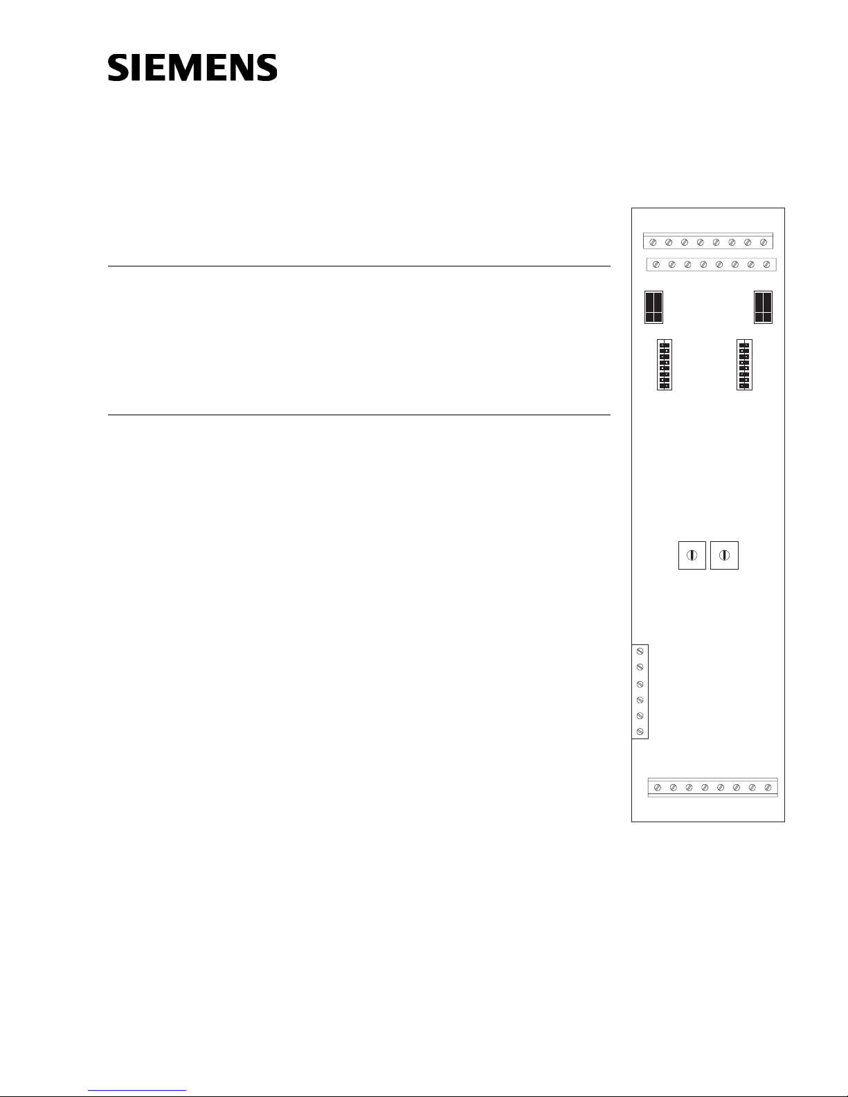
INTRODUCTION The SIEMENS Model OCM-16 Output Control Module
is a remotely located, general purpose output module. It
provides sixteen open collector outputs to drive LEDs,
incandescent lamps, or external relays. There is an
additional output for a local audible and two inputs for
momentary lamp test and local audible silence switches.
OPERATION The OCM-16 is mounted in an enclosure that is re-
motely located from the Main Panel. Communication
between the OCM and the NIC-C is through the Control
Area Network (CAN) bus. Each OCM-16 has two 10
position rotary switches that are used to set the board
address on the CAN which is a sub-address of the
NIC-C. The 16 outputs of the OCM-16 are controlled by
messages received from the NIC-C over the CAN.
A CAN message can activate any or all of the 16 outputs
to drive LEDs, incandescent 24 Volt lamps or relays.
TB1
OCM-16
12345678
910111213141516
P2
1
2
3
4
S1
5
6
7
8
5
5
6
6
4
4
3
2
7
7
3
8
8
2
9
9
1
1
0
0
P3
1
2
3
4
S2
5
6
7
8
P/N 315-033150-3
Whenever any of the outputs is activated, (LEDs, lamps
or relays ON) the local audible (if installed) will sound
until it is acknowledged by shorting position 19 and 20
on TB2. If the outputs are deactivated before the alarm
(local audible) is acknowledged, the alarm (local
audible) will cease to sound.
By shorting terminals 17 and 18, all LEDs or lamps will
turn on to confirm that they are working and automatically will return to their normal state after a few seconds. Both the lamp test and local audible silence
switch on multiple OCM-16s can be connected to a
single switch, one for each function. A single audible
can also be used with multiple OCM-16s.
Siemens Building Technologies
TB3
17 18 19 20 21 22 23 24
TB2
Figure 1
OCM-16 Output Control
Module
Fire Safety
Page 2
PRE-INSTALLATION Rotary Address Switches - Set the board address for each OCM-16 using both of
the ten-position rotary switches located on the board (See Figure 2). Each of these
addresses must be a sub-address of the NIC-C and must be the same as the addresses assigned in the Zeus Programming Tool.
S1/S2 LED, Incandescent/Relay Select Switches
When LEDs are used, open corresponding dipswitches on S1 and S2 (Refer
to OCM-16 Switches Table) to provide a current limiting resistor of 2.7K
ohms to each LED.
When incandescent lamps or relays are used, close corresponding
dipswitches on S1 and S2 (Refer to OCM-16 Switches Table) to bypass the
limiting resistors.
SEHCTIWS61-MCO
1BT
11-1S9 1-2S
22-1S012-2S
33-1S113-2S
44-1S214-2S
55-1S315-2S
66-1S416-2S
77-1S517-2S
88-1S618-2S
1S
hctiwS
1BT
2S
hctiwS
INSTALLATION An OCM-16 may be installed in a REMBOX. When using REMBOX 2 or 4, mount the
OCM-16 in one module space on a REMBOX2-MP, P/N 500-634211 or REMBOX4-MP,
P/N 500-634212 using the four screws provided. (Refer to REMBOX2-MP/REMBOX4MP Installation Instructions, P/N 315-034211.) Up to 4 OCM-16s will fit in a
REMBOX2; up to 8 OCM-16s will fit in a REMBOX4.
WIRING
Disconnect BATTERY and AC prior to working on equipment.
Each OCM-16 module is a node in the CAN bus.
The OCM-16 can be installed with or without an RNI. Connect 24V and
CAN bus as shown in Figures 2 and 3.
Up to 99 CAN modules, in any combination, can be connected to the CAN
bus of each NIC-C.
Each OCM-16 module is shipped with one CCS cable.
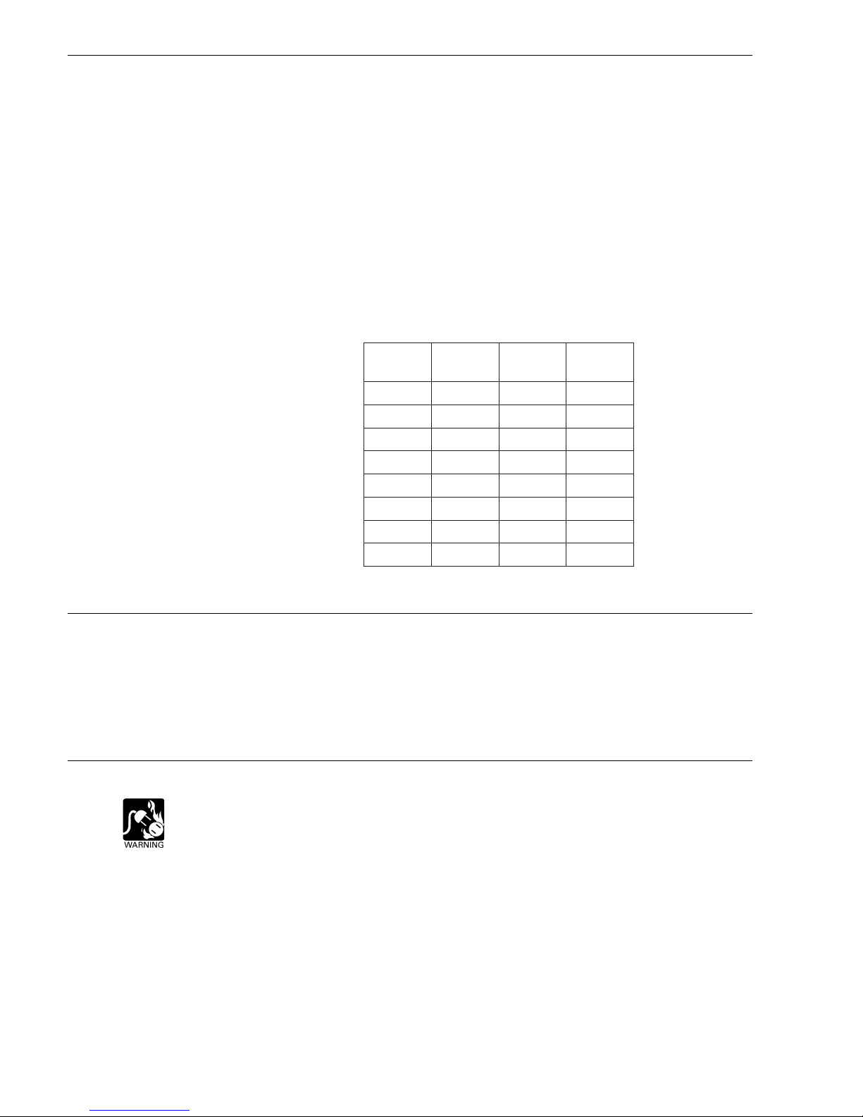
Cable connections for OCM-16 modules are shown in the following table:
Siemens Building Technologies
Fire Safety
P/N 315-0033150-32
Page 3

elbaCnoitpircseDrebmuNtraPnoitcennoC
SNOITCENNOCELBAC61-MCO
NOTES
1. All wiring must be in
accordance with Article 760
of NEC or local building
codes.
2. All circuits are power limited
to NFPA 70 per NEC 760.
3. Electrical Ratings:
Standby current: 14mA max.
@ 24VDC
Active current: 200mA max.
@ 24VDC
4. For additonal information,
refer to the NIC-C Installation Instructions, P/N 315-
033240.
5. All wiring to TB1 must be:
- within the same room
- within 20 feet
- in rigid conduit
6. Lamp test switch, ACK alarm
switch, and audible device
must be UL 864 listed
devices.
7. CAN network max. line
resistance 16S.
8. Mount the Lamp Test, Ack
Alarm and Audible Device on
the REMBOX2/4 front door.
9. Wiring for TB1 and TB2 is 18
AWG min., 12 AWG max.
10. Wiring for TB3 is 26 AWG
min., 16 AWG max.
LCCgnoL-ELBAC-NAC
412436-995.61-MCOtsrifotINRno4PstcennoC
rotcudnoc-6,.ni03
SCCtrohS-ELBAC-NAC
935331-55561-MCOotseludom61-MCOstcennoC
rotcudnoc-6,.ni½5
The CAN bus requires a 120S resistance at each end of the loop. Refer to the NIC-C
Installation Instructions, P/N 315-033240 for details about CAN termination.
TO PSC-12/PSX-12, TB3
OR ANY REGULATED
POWER LIMITED POWER
SUPPLY LISTED FOR
FIRE PROTECTIVE
SIGNALING USE
TO PSC-12, TB1
SEE NIC-C
INSTALLATION
INSTRUCTIONS,
P/N 315-033240
FOR WIRING DETAILS
LAMP TEST*
ACK ALARM*
AUDIBLE
DEVICE**
USE UP TO 16 LED / INCANDESCENT
IN ANY COMBINATION (UNSUPERVISED)
TB1
12345678
910111213141516
P2
ON ON
1
2
3
4
S1
5
6
7
8
OCM-16
S4 S3 S4 S3
5
5
6
4
4
7
3
3
8
2
2
9
1
1
0
TB3
+24 V
24 V RET
SHIELD
CAN +
SUPERVISED
CAN –
SHIELD
17 18 19 20 21 22 23 24
+
–
*NORMALLY OPEN MOMENTARY PUSHBUTTON (UL 864 LISTED)
**24VDC AUDIBLE 50mA MAX. (UL 864 LISTED)
/ RELAY
24VDC
RELAY
COIL
/
P3
S2
CORRESPONDING
DIPSWITCH ON
MUST BE SET TO
OFF FOR LEDs.
1
2
3
4
5
6
7
8
USE UP TO 16 LED / INCANDESCENT
IN ANY COMBINATION
TB1
12345678
910111213141516
1
2
3
S1/S2
4
5
6
7
8
P2
ON ON
S1
OCM-16
6
7
8
9
0
ROTARY
ADDRESS SWITCHES
TB2 TB2
5
6
4
3
2
1
0
TB3
+24 V
24 V RET
SHIELD
CAN +
CAN –
SHIELD
17 18 19 20 21 22 23 24
(UNSUPERVISED)
(UNSUPERVISED)
P3
1
2
3
4
5
6
7
8
5
6
4
7
7
3
8
8
2
9
9
1
0
DO NOT USEDO NOT USE
/ RELAY
24VDC
RELAY
COIL
/
INSERT CAN TERMINATOR
IF THIS IS THE LAST
MODULE ON THE PANEL.
S2
(UNSUPERVISED)
/MCFot61-MCOmorfstcennocoslA
.)roodno(seludomBSC/MCS/MCL
worelgnisaniseludom61-MISro
P/N 110-134215
INTOP2orP3
TO NEXT
OCM-16
Figure 2
OCM-16 Wiring Without An RNI
Siemens Building Technologies
Fire Safety
P/N 315-033150-33
Page 4

CABLE
MODEL
# CCS
ELECTRICAL RATINGS
TO RNI, P4
CABLE
MODEL
12345678 12345678 12345678 12345678
9 10 11 12 13 14 15 16 9 10 11 12 13 14 15 16 9 10 11 12 13 14 15 16 9 10 11 12 13 14 15 16
1
1
2
2
3
3
4
4
S1
5
5
6
6
7
7
8
8
1
1
2
2
3
3
4
S2
4
S1
5
5
6
6
7
7
8
8
1
2
3
4
S2
5
6
7
8
# CCL
OCM-16 OCM-16 OCM-16 OCM-16
5
5
6
6
4
4
7
7
3
3
8
8
2
2
9
9
1
1
0
0
17 18 19 20 21 22 23 24 17 18 19 20 21 22 23 24 17 18 19 20 21 22 23 24 17 18 19 20 21 22 23 24
5
5
6
6
4
4
7
7
3
3
8
8
2
2
9
9
1
1
0
0
Figure 3
OCM-16 CAN Bus Connections With An RNI
1
2
3
4
S1
5
6
7
8
5
5
6
6
4
4
7
7
3
3
8
8
2
2
9
9
1
1
0
0
1
2
3
4
S2
S1
5
6
7
8
5
6
4
7
3
8
2
9
1
0
CAN TERMINATOR,
1
2
3
4
5
6
7
8
5
6
4
7
3
8
2
9
1
0
P/N 110-134215
S2
(SHIPPED WITH NIC-C)
tnerruCenalPkcaBV420
tnerruCV42lanimreTwercSDELevitcarepAm01+Am41
tnerruCenalPkcaBV2.60
tnerruCybdnatSV42DELevitcarepAm01+Am41
For CE applications in Cerberus E100 systems refer to
Installation Instruction A24205-A334-B844 (English) or A24205-A334-A844 (German).
Siemens Building Technologies, Inc.
8 Fernwood Road
Florham Park, New Jersey 07932
Siemens Building Technologies, Ltd.
2 Kenview Boulevard
Brampton, Ontario L6T 5E4 CN
Siemens Gebäudesicherheit
GmbH & Co. oHG
D-80930 München
P/N 315-033150-3
 Loading...