

Page 1

Installation Instructions
Model OCC-1
Output Control Card
INTRODUCTION
Fire Safety
The Model OCC-1 Output Control Card
from Siemens Building Technologies, Inc.
is an MXLV module that controls Voice
system cards (such as the zone cards)
that plug into the OMM-1 Output Master
module. Commands received from the
MXL system through the network bus are
processed by the OCC-1. The commands
are then sent to the other cards in the
system for implementation.
At least one OCC-1 is required in each
MXLV System. It supervises and controls
up to 11 plug-in cards, each having a
unique subaddress. Several types of
system cards connect to the OCC-1.
1. Up to three audio risers connect to the
OCC-1. These signals are available to
the power amplifiers.
2. The BTC-1 Backup Tone card is an
optional module that also plugs into
the OCC-1. In an installation with
distributed amplification, the BTC
provides the tone for the degrade
mode of operation; then, if Network
Communications fail and a local alarm
is detected, the tone from BTC-1 is
available at the Channel A amplifier
input.
3. The telephone riser also connects to
the OCC-1. The telephone signal is
routed through the OMM-1 telephone
riser bus to any ZCT-8B telephone
zone control cards that are plugged
into the OMM-1.
The OCC-1 supervises the cards under its
control, such as the ZC zone card series.
As each card is supervised by the OCC-1,
the card responds with its status. The
status information is then sent to the MXL.
The OCC-1 occupies a network address.
Set the address on switch S1. When
installing an OCC-1 card, use the CSG-M
(AccuLINK) configuration printout to locate
the address of the card. Follow the switch
setting instructions in Table 1 to set the
desired address.
For additional information on the Voice
System, refer to the MXL/MXLV Manual,
P/N 315-092036.
INSTALLATION
Remove all system power before
installation, first the battery and
then AC. (To power up, connect the
AC first and then the battery.)
1. Remove the card from its protective
bag. Do not touch the gold edge of the
board.
2. Refer to the CSG-M configuration
printout for the address of the module.
Siemens Building Technologies, Inc.
8 Fernwood Road
Florham Park, New Jersey 07932
P/N 315-090918-12
Siemens Building Technologies, Ltd.
2 Kenview Boulevard
Brampton, Ontario L6T 5E4 Canada
Page 2
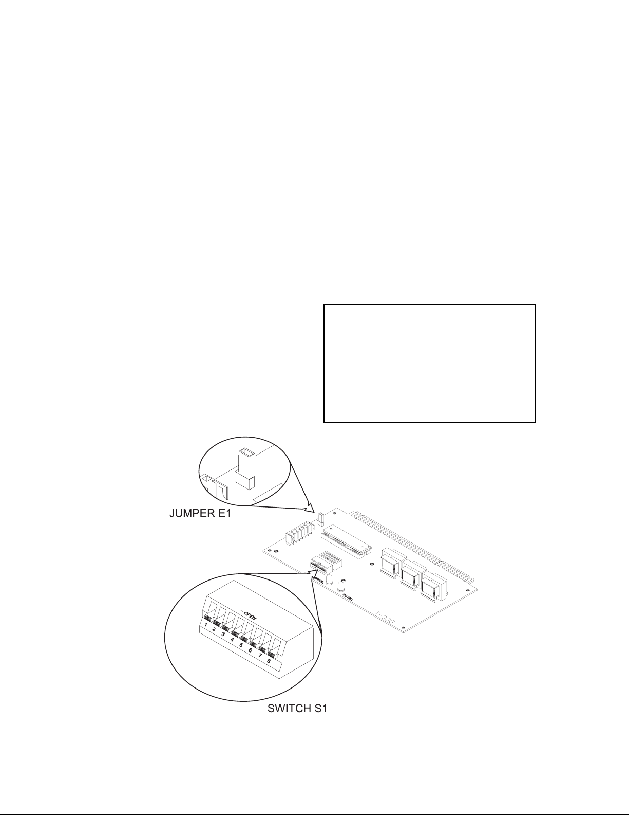
3. Set the card address on switch S1
using dipswitches SW1-SW8.
a. Refer to Figure 1 for the location of
switch S1.
b. Refer to Table 1 for the switch
settings.
c. Set the address (See NOTE below).
NOTE: To open a dipswitch, press
down on the side of the dipswitch
marked OPEN. To close a dipswitch, press down on the side of
the dipswitch opposite the side
marked OPEN.
To open a slide switch, push
the slide to the side opposite the
side marked ON. To close a slide
switch, push the slide to the side
marked ON.
4. There is a jumper E1 on the OCC-1.
Refer to Figure 1 for its location. If the
EL-410C/D amplifier is used, place
jumper E1 in the right-hand position.
This connects the backup amplifier
input negative side to the MXLV power
supply.
5. Switch S2 is not presently used, but it
must be left in place.
6. Do NOT install the card in its edge
connector until ALL OMM-1/-2 field
wiring is completed and checked for
shorts, opens, and other faults. Refer
to Wiring and to the OCC-1 Wiring
Checkout Chart. Replace the card in
its protective bag if the wiring is not
complete.
7. Place the user key from the installation kit in the OMM-1/-2 card edge
connector for the OCC-1 (See Figure
2). See Figure 3 for the exact location
of the key for this module. This prevents installation of any other card
type in the OCC-1 slot.
CAUTION
At all times handle any plug-in
cards with extreme care. When inserting or removing a card, be
sure the card is kept at right
angles to the OMM board. Otherwise, the plug-in card can damage
or displace other components.
OCC-1 Output Control Card Module
Figure 1
2
Page 3
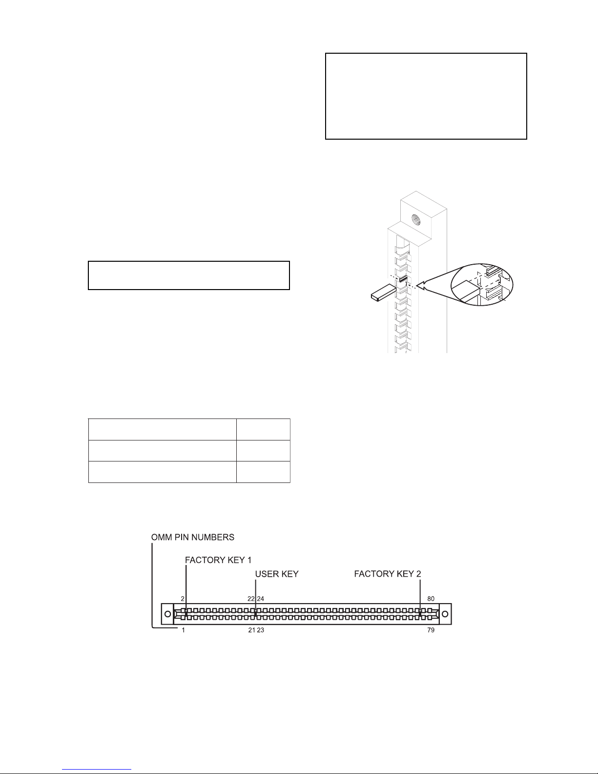
8. Two keys to prevent reverse installation of the card are already factory
installed in the OMM-1/-2 edge connectors (See Figure 3).
End of Line Resistors
Audio risers: 10K, 1/2W, 5%
(P/N 140-820396)
9. After completing and checking all field
wiring, place the card in its card edge
connector. The components on the
board must face the 22-position
terminal block where the wiring is
terminated. Press the card firmly in
place to be sure it is seated properly in
the edge connector.
WIRING
(Refer to Figure 4)
All wiring must comply with
national and local codes.
Maximum wire size:
14 AWG shielded twisted pair
Minimum wire size:
18 AWG shielded twisted pair
Maximum loop resistance:
20 ohms for both wires
ELECTRICAL RATINGS
Telephone risers: 5.6K, 1/2W, 5%
(P/N 140-820390)
Figure 2
Installing the User Key in the OMM
Card Edge Connector
tnerruCeludoMCDV5evitcAAm01
tnerruCeludoMCDV42evitcAAm01
tnerruCeludoMCDV42ybdnatSAm51
Figure 3
Location of the User Key for the OCC-1
3
Page 4

All wiring must conform to National and Local codes.
1
2
3
4
5
6
7
8
9
10
11
12
13
14
15
16
EOL
CONNECT AN EOL ONLY IF
*
THIS IS THE LAST OCC-1 CARD
+
-
SHIELD
+
-
SHIELD
+
-
SHIELD
TO TERMINAL 8,
EL-410C/D
FOR USE WITH PL864-25S ONLY
*
AUDIO
RISER 2
AUDIO
RISER 3
TELEPHONE
RISER
SEE NOTE 4
SUPERVISED, POWER LIMITED
SEE NOTES 1 AND 2
AUDIO RISER 1 +
AUDIO RISER 1 -
AUDIO RISER 1 SHIELD
AUDIO RISER 1 +
AUDIO RISER 1 -
AUDIO RISER 1 SHIELD
Notes:
1. If this OCC-1 is the last or the only OCC-1, terminate the
inputs shown as follows:
Audio risers: 10K, ½W, 5% (P/N 140-820396)
Telephone riser: 5.6K, ½W, 5% (P/N 140-820390)
2. Maximum loop resistance: 20 ohms for telephone and audio
risers.
3. Minimum wire size: 18 AWG twisted pair, shielded
Maximum wire size: 14 AWG twisted pair, shielded
4. Configure Generic input with CSG-M for either NC or NO dry
contact input or normally low or normally high 5/24 VDC input.
Generic input supervision is enabled in CSG-M for any type of
power failure.
a. Wire the NC or NO dry contact input across terminals
13 and 14.
b. Wire the normally low or normally high 5/24 VDC input
to terminal 14. (Normally low = high going input;
Normally high = low going input. The EL-410C/D power/
battery supervision is normally low input.)
5. Refer to Wiring Specification for MXL, MXL-IQ and MXLV
Systems, P/N 315-092772 revision 6 or higher, for additional
wiring information.
6. Positive and negative ground fault detected at <70K ohms
for terminals 17-22.
TO THE NEXT
OCC-1 IN THE
SYSTEM
FROM THE TBM
OR PREVIOUS
OCC-1 IN THE
SYSTEM
17
18
19
20
21
22
TO CHANNEL A AMPLIFIER 1 INPUT +
TO CHANNEL A AMPLIFIER 1 INPUT -
TO CHANNEL B AMPLIFIER 2 INPUT +
TO CHANNEL B AMPLIFIER 2 INPUT -
TO CHANNEL C AMPLIFIER 3 INPUT +
TO CHANNEL C AMPLIFIER 3 INPUT -
SUPERVISED, POWER LIMITED
PLACE AMPLIFIER INPUT AND OUTPUT CABLES
IN SEPERATE CONDUITS
Figure 4
Typical Riser Connections
4
TERMINATE THE
SHIELD ONLY AT
THE EL-410C/D
AMPLIFIER
Page 5

OCC-1 WIRING CHECKOUT CHART
Resistence
Between
Resistance
Desired
Possible Cause of
Problem
Terminals
1 to 2
4 to 5
7 to 8
10 to 11 5.6K
1-22 to chassis > 1 Meg Short in wiring
2 to 3
3 to 4
5 to 6
6 to 7
8 to 9
9 to 10
11 to 12
12 to 13
10K
> 1 Meg Short in wiring
Line shorted
Line open
No EOL
Wrong EOL
Line shorted
Line open
No EOL
Wrong EOL
17 to 18
19 to 20
21 to 22
16 to 17
18 to 19
20 to 21
> 1 Meg Line shorted
> 1 Meg Short in wiring
5
Page 6

1ELBAT
GNIMMARGORPSSERDDAKROWTEN
RDDA12345678RDDA12345678RDDA12345678RDDA12345678
000
100
200
300
400
500
600
700
800
900
010
110
210
310
410
510
610
710
810
910
020
120
220
320
420
520
620
720
820
920
030
130
230
330
430
530
630
730
830
930
040
140
240
340
440
540
640
740
840
940
050
150
250
35
0
450
550
650
750
850
950
060
160
260
360
LAGELLI
LAGELLI
LAGELLI
XXOOOOOO
OOXOOOOO
XOXOOOOO
OXXOOOOO
XXXOOOOO
OOOXOOOO
OOXOOOO
X
OXOXOOOO
XXOXOOOO
OOXXOOOO
XOXXOOOO
OXXXOOOO
XXXXOOOO
OOOOXOOO
XOOOXOOO
OXOOXOOO
XXOOXOOO
OOXOXOOO
OO
XOO
XOXOXO
OXXOXOOO
XXXOXOOO
OOOXXOOO
XOOXXOOO
OXOXXOOO
XXOXXOOO
OOXXXOOO
XOXXXOOO
OXXXXOOO
XXXXXOOO
OOOOOXOO
XOOOOXOO
OXO
OOXOO
XXOOOXOO
OOXOOXOO
XOXOOXOO
OXXOOXOO
XXXOOXOO
OOOXOXOO
XOOXOXOO
OXOXOXOO
XXOXOXOO
OOXXOXOO
XOXXOXOO
OXXXOXOO
XXXXOXOO
OOOOXXOO
XOOOXXOO
OXOOXXOO
XXOOXXOO
OOXOXXOO
XOXOXXOO
OXXOXXOO
XXXOXXOO
OOOXXXOO
XOOXXXOO
OXOXXXOO
XXOXX
OOXXXXOO
XOXXXXOO
OXXXXXOO
XXXXXXOO
460
560
660
760
860
960
070
170
270
370
470
570
670
770
870
970
080
180
280
380
480
580
680
780
880
980
090
190
290
390
490
590
690
790
890
990
001
101
201
301
401
501
601
701
801
901
011
111
211
311
411
511
611
711
811
91
1
021
121
221
321
421
521
621
721
XO
)NOro(DESOLC=X)FFOro(NEPO=O
OOOOOOXO
XOOOOOXO
OXOOOOXO
XXOOOOXO
OOXOOOXO
XOXOOOXO
OXXOOOXO
XXXOOOXO
OOOXOOXO
OOXO
XOOX
OXOXOOXO
XXOXOOXO
OOXXOOXO
XOXXOOXO
OXXXOOXO
XXXXOOXO
OOOOXOXO
XOOOXOXO
OXOOXOXO
XXOOXOXO
OOXOXOXO
XOXOXOXO
O
XXOXOXO
XXXOXOXO
OOOXXOXO
XOOXXOXO
OXOXXOXO
XXOXXOXO
OOXXXOXO
XOXXXOXO
OXXXXOXO
XXXXXOXO
OOOOOXXO
XOOOOXXO
OXOOOX
XXOOOXXO
OOXOOXXO
XOXOOXXO
OXXOOXXO
XXXOOXXO
OOOXOXXO
XOOXOXXO
OXOXOXXO
XXOXOXXO
OOXXOXXO
XOXXOXXO
OXXXOXXO
XXX
XOXXO
OOOOXXXO
XOOOXXXO
OXOOXXXO
XXOOXXXO
OOXOXXXO
XOXOXXXO
OXXOXXXO
XXXOXXXO
OOOXXXXO
XOOXXXXO
OXOXXXXO
XXOXXXXO
OOXXXXXO
XOXXXXXO
OXXXXXXO
XXXXXXXO
821
921
031
131
231
331
431
531
631
X
731
831
931
041
141
241
341
441
541
641
741
841
941
051
151
251
351
451
551
651
751
851
951
061
161
261
361
461
561
661
761
861
961
071
171
271
371
471
571
671
771
871
971
081
181
281
381
48
1
581
681
781
881
981
091
191
OX
OOOOOOOX
XOOOOOOX
OXOOOOOX
XXOOOOOX
OOXOOOOX
XOXOOOOX
OXXOOOOX
XXXOOOOX
OOOXOOOX
XOOXOOO
OXOXOOOX
XXOXOOOX
OOXXOOOX
XOXXOOOX
OXXXOOOX
XXXXOOOX
OOOOXOOX
XOOOXOOX
OXOOXOOX
XXOOXOOX
OOXOXOOX
XOXOXOOX
OXXO
XOOX
XXXOXOOX
OOOXXOOX
XOOXXOOX
OXOXXOOX
XXOXXOOX
OOXXXOOX
XOXXXOOX
OXXXXOOX
XXXXXOOX
OOOOOXOX
XOOOOXOX
OXOOOXOX
X
XOOOXOX
OOXOOXOX
XOXOOXOX
OXXOOXOX
XXXOOXOX
OOOXOXOX
XOOXOXOX
OXOXOXOX
XXOXOXOX
OOXXOXOX
XOXXOXOX
OXXXOXOX
XXXXOX
OOOOXXOX
XOOOXXOX
OXOOXXOX
XXOOXXOX
OOXOXXOX
XOXOXXOX
OXXOXXOX
XXXOXXOX
OOOXXXOX
XOOXXXOX
OXOXXXOX
XXOXXXOX
OOX
XXXOX
XOXXXXOX
OXXXXXOX
XXXXXXOX
291
391
491
591
691
791
891
991
002
102
202
302
402
502
602
702
802
902
012
112
212
312
X
412
512
612
712
812
912
022
122
222
322
422
522
622
722
822
922
032
132
232
332
432
532
632
732
832
932
042
142
242
342
442
542
642
742
842
94
2
052
152
252
352
452
552
ELLI
OOOOOOXX
XOOOOOXX
OXOOOOXX
XXOOOOXX
OOXOOOXX
XOXOOOXX
OXXOOOXX
XXXOOOXX
OOOXOOXX
XOOXOOXX
OXOOXX
OX
XXOXOOXX
OOXXOOXX
XOXXOOXX
OXXXOOXX
XXXXOOXX
OOOOXOXX
XOOOXOXX
OXOOXOXX
XXOOXOXX
OOXOXOXX
XOXOXOXX
OXXOXOX
XXXOXOXX
OOOXXOXX
XOOXXOXX
OXOXXOXX
XXOXXOXX
OOXXXOXX
XOXXXOXX
OXXXXOXX
XXXXXOXX
OOOOOXXX
XOOOOXXX
OXOOOXXX
XXOO
OXXX
OOXOOXXX
XOXOOXXX
OXXOOXXX
XXXOOXXX
OOOXOXXX
XOOXOXXX
OXOXOXXX
XXOXOXXX
OOXXOXXX
XOXXOXXX
OXXXOXXX
XXXXOXXX
O
OOOXXXX
XOOOXXXX
OXOOXXXX
XXOOXXXX
OOXOXXXX
XOXOXXXX
OXXOXXXX
XXXOXXXX
LAGELLI
LAGELLI
LAGELLI
LAGELLI
LAGELLI
LAG
LAGELLI
LAGELLI
6
Page 7

7
Page 8

Siemens Building Technologies, Inc.
8 Fernwood Road
Florham Park, New Jersey 07932
P/N 315-090918-12
Siemens Building Technologies, Ltd.
2 Kenview Boulevard
Brampton, Ontario L6T 5E4 Canada
 Loading...