

Siemens NRC Installation Instructions Manual
Installation Instruct ions
Model NRC
Network Ring Card
INTRODUCTION The Model NRC Network Ring card from Siemens Industry,
Inc. is a card that networks multiple FireFinder-XLS systems
together in a Class X (Style 7) ring. The NRC can also be
configured for Class B (Style 4) operation in systems where
a ring is not required, as an alternative to the NIC-C card.
It provides communication between its host FireFinder-XLS
system and other FireFinder-XLS systems on an XNET network.
It replaces the NIC-C when a ring connection is needed.
The NRC can also be used to connect an NCCNT-G to the
XNET network. In this configuration, all events occurring on
the FireFinder-XLS network are displayed at the NCCNT-G.
NRC
RESET
POWER
CARD FAIL
TROUBLE
One NRC is required in each FireFinder-XLS system on the
network. This NRC must reside in the same enclosure as the
PMI/PMI-2.
The NRC supervises the network to ensure proper operation. Any faults that are detected by the NRC are reported to
the PMI/PMI-2 for annunciation. In addition, the NRC has
diagnostic LEDs that indicate which faults have been found.
The NRC performs ground fault detection on its outgoing
ring port.
Features The NRC isolates faults to the individual link in trouble. When
wired for Class X (Style 7), network ring communication
continues unaffected.
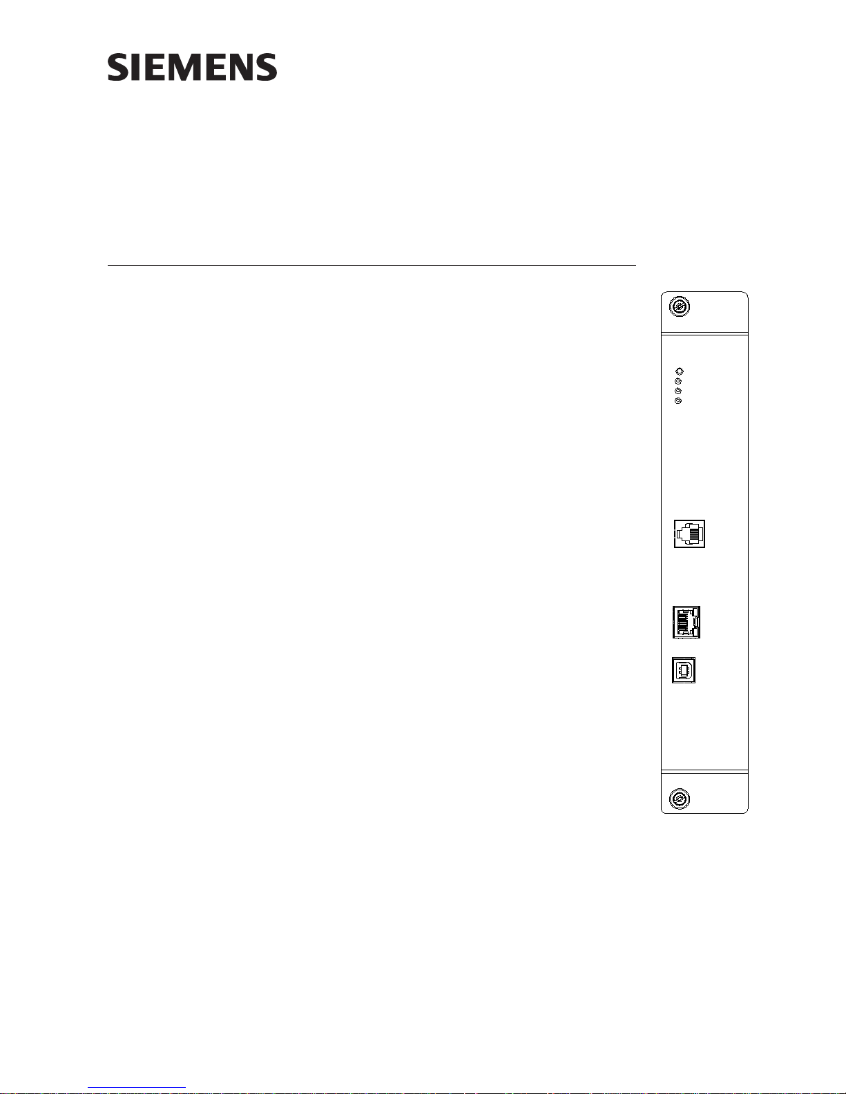
An RJ-12 monitor jack is included for connection of XNET
diagnostic tools. In addition, RJ-45 and USB jacks are
included for firmware download. These jacks are located on
the front bezel.
MONITOR
PORT
ETHERNET
USB
Figure 1
NRC Network Ring Card
A6V10322639_b_en_--
Building Building
Building
Building Building
Siemens Siemens
Siemens
Siemens Siemens
TT
ecec
hnologies Dihnologies Di
T
ec
hnologies Di
TT
ecec
hnologies Dihnologies Di
IndustryIndustry
Industry
IndustryIndustry
visionvision
vision
visionvision
,,
Inc. Inc.
,
Inc.
,,
Inc. Inc.
OPERATION The NRC continuously monitors the network for activity and reports any problems to
the PMI/PMI-2. In some cases, a reset at the PMI/PMI-2 is required to clear network
troubles.
Controls and Indicators The front panel of the NRC contains one reset switch, three
LEDs, one Monitor port, one USB port, and one Ethernet port as shown in
Figure 1.
A reset switch is located on the top of the front panel. Pushing the reset switch
reinitializes the NRC.
The LEDs follow the reset switch and their functions are defined as follows:
POWER (Green) Normally ON. When illuminated, indi-
cates that power for the NRC is applied
to the card.
CARD FAIL (Yellow) Normally OFF. When illuminated, indicates
that the card microprocessor has failed.
TROUBLE (Yellow) Normally OFF. When illuminated, indi-
cates trouble in the Network such as
wire faults or module failure. The Trouble
LED will illuminate under the following
conditions:
1. Wire faults (open or short) in either
Port 1 (In) or Port 2 (Out)—See Figure 5.
2. Ground fault on outgoing port (Port 2).
3. XNET communications problems
between the PMI/PMI-2 and the NRC.
PRE-INSTALLATION The NRC does not have a network address but it does need to be included in the
Zeus configuration.
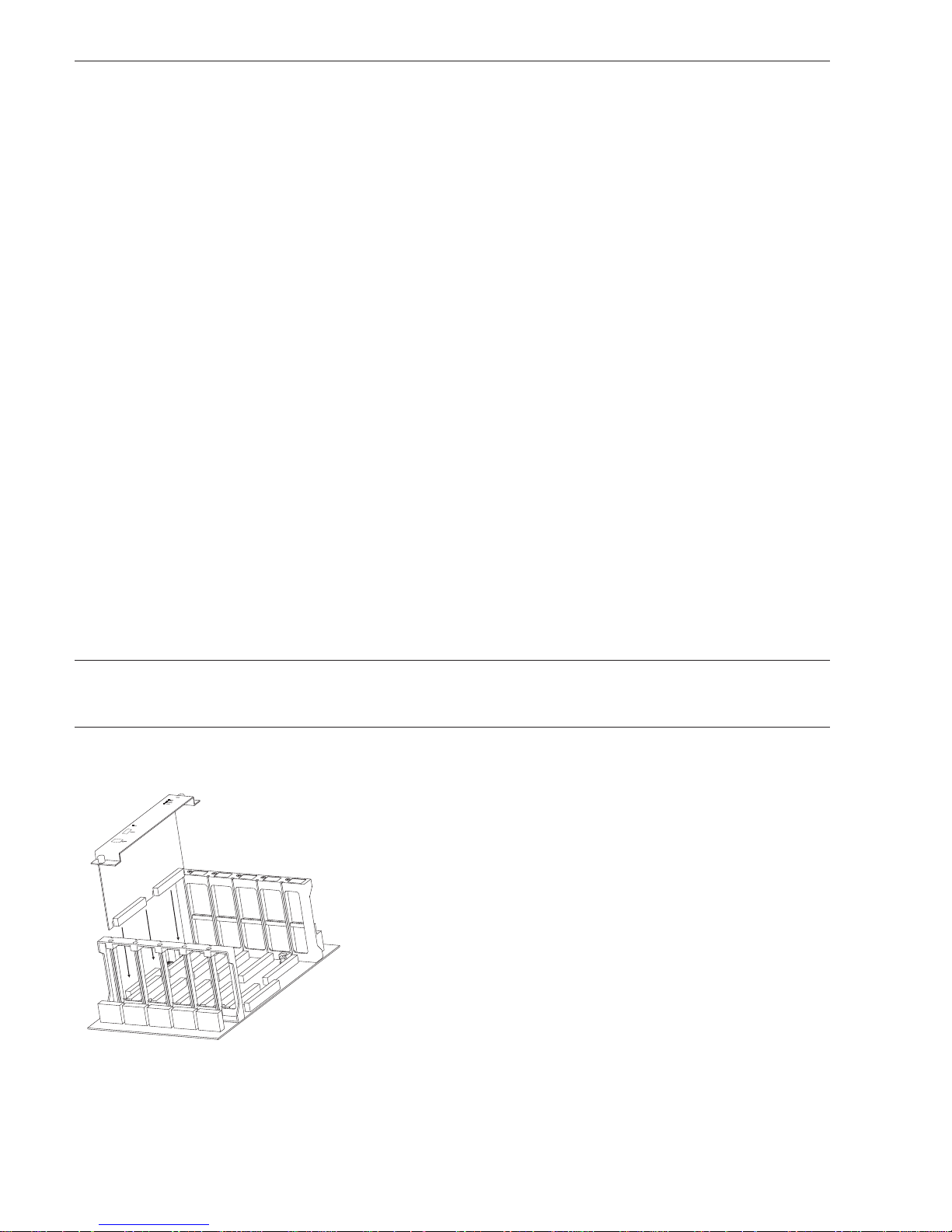
INSTALLATION The NRC plugs perpendicularly into one slot in the CC-2 or CC-5 card-cage via two
96-pin DIN connectors (only 64-pins are used) and can occupy any slot in the card
cage. (Refer to Figure 2.)
Slide the NRC card into the card guides front bezel up (lettering on the
front panel is legible) until the card cage connectors contact the
motherboard receptacles.
Verify that the card edge connectors align properly with the
motherboard receptacles. There is only one correct way to plug in the
card. If it does not align, DO NOT FORCE the card.
Place thumbs on the front panel adjacent to the captive screws and
gently apply even pressure on the card until the connectors plug firmly
into the motherboard receptacles. Secure the NRC to the card cage with
the captive screws.
Figure 2
Installing the NRC
Siemens Industry, Inc.
Building Technologies Division
2 A6V10322639_b_en_--
FIRMWARE UPGRADES From time to time, modules used in XLS systems are upgraded to improve their
operation or to add to their capabilities with new features. Firmware in the NRC is
field upgradable. Refer to the Zeus Quickstart Manual, P/N 315-033875, and Zeus
Help for additional details.
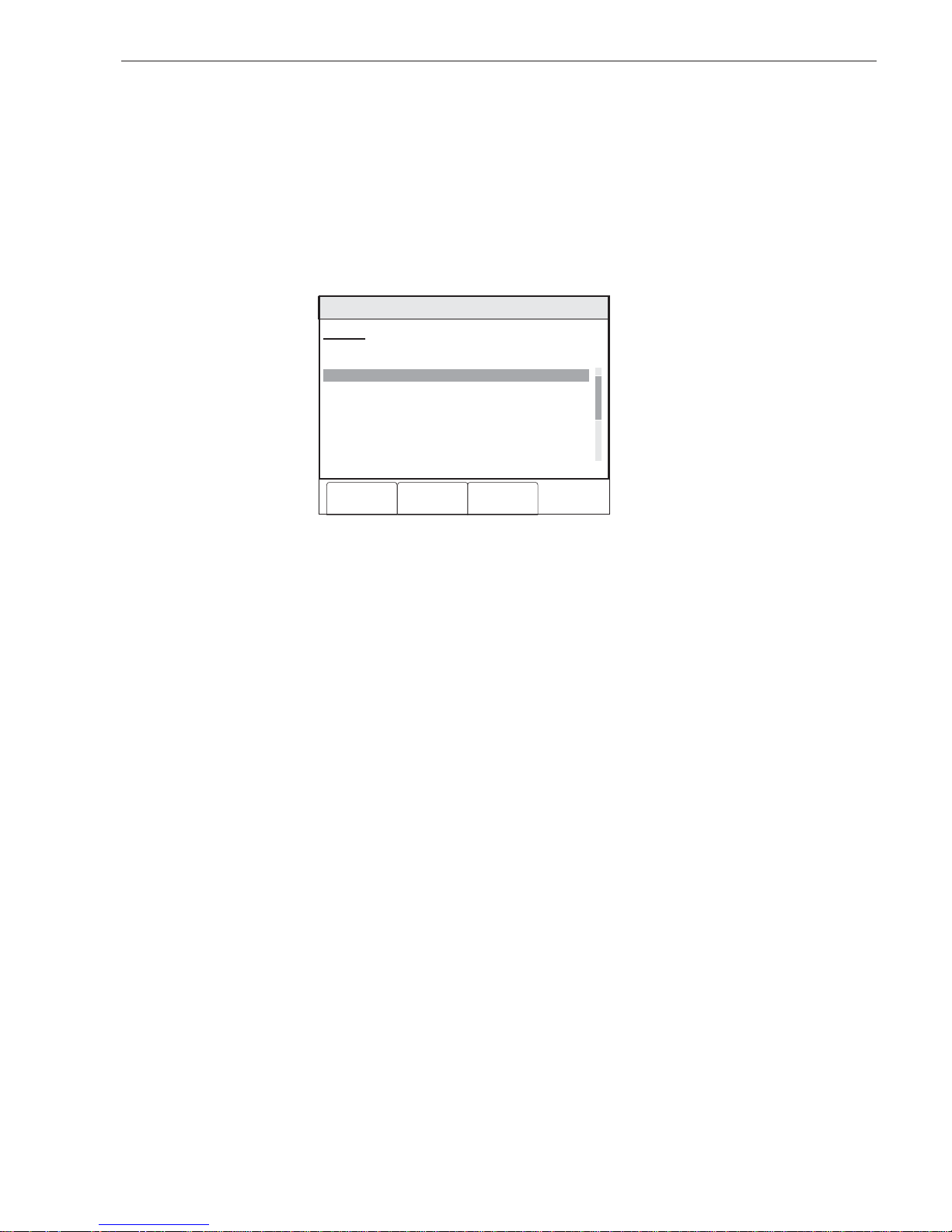
Find NRC Software Version To check for the current version of NRC software in an installed NRC, go to the PMI/
PMI-2 and press the Menu button, select Report, press the More Info button and
select the PMI. Press the Configuration soft key and “Touch” Appl Rev for the
Application Version. The NRC software version will be shown with the PMI software
version. Refer to Figure 3 for an example of a display.
Menu:Report:Configuration:Appl.Rev:View
PHY:MultiXNet, FireFinder, PMI-C@253
Application Rev Report
Address Entity Software Version 100%
/1:253 PMI-C 07.00.0034
/1:253^1 NRC 01.00.0008
10:53
Category text information
Cancel Print
GoTo
Figure 3
Typical PMI Display of NRC Software Version
Siemens Industry, Inc.
Building Technologies Division
3 A6V10322639_b_en_--
 Loading...