

Page 1
GAMMA instabus
Technical Product Information
March 2014
IP Router N146/02 5WG1 146-1AB02
Siemens AG N 146/02, 8 pages Technical Manual
Infrastructure & Cities Sector, Building Technologies
Control Products and S ystem s ã Siemens AG 2014 Update: http://www.siemens.com
P.O.Box 10 09 53, D-93009 Regensburg Subject to change without prior notice
2.11.1.13/1
Product and Applications Description
The IP Router N146/02 is a DIN rail mounted device.
The device implements the KNXnet/IP standard and
connects KNX/EIB lines via data networks using the
Internet Protocol (IP). Also this device offers concurrent
access to the bus line from any PC or other data
processing equipment.
The physical connection to the KNX/EIB is established
via a bus connector terminal block. For connection to the
data network (IP via 10BaseT) the device contains an
RJ45 socket.
By using a LAN modem an KNX/EIB installation can be
remotely accessed even if there is no direct data
network connection between a PC and an IP Router.
LAN modems are available on the market for standard
telephone, ISDN or DSL connections.
The IP Router requires additional operating power for its
operation. The IP Router N146/02 can source this
operating power via the network connection from “Power
over Ethernet” according to IEEE 802.3af. Alternatively,
the operating power can be provided via a second
term inal blo ck ( whit e-y ell ow term in als) by a safet y ext ra
low voltage (SELV) power supply AC/DC 24 V or by a
bus power supply (unchoked power, DC 29V). When a
SELV power supply is connected the operating power is
sourced from it.
The IP Router has th ese ch arac teri stics:
· Simpl e con nec t i on t o hi er ar c hi cally su per i m po s ed
systems via Internet Protocol (IP)
· Direct access to the KNX/EIB installation from any
access point to the IP network (KNXne t/IP Tunneling)
· F as t comm u ni c at i on bet ween K NX / EI B li nes , ar ea s
and systems (KNXnet/IP Routing)
· Communication between buildings and facilities
· Fi ltering and routing of telegrams depending on
- individual address
- group address
· LED display of
- operation
- KNX/EIB communication
- IP communication
· Simple configuration with standard ETS
· Easy connection to SCADA and Facility Management
systems (see: Supported Software)
IP Router as line / area coupler (KNXnet/IP Routing)
Using the existing data network for communication
between bus lines in non-residential buildings is a logical
step. The advantages are: fast communication between
KNX/EIB lines, extension of an KNX/EIB system beyond
one building by using LAN and WAN connections, direct
transmission of KNX/EIB data to any network user,
KNX/EIB remote configuration from any network access
point.
The IP Router logically connects KNX/EIB bus lines by
transmitting KNX/EIB telegrams between them via a
data network but separates them galvanically. This
allows to run each bus line independently from other bus
lines.
The IP Router can be used as line coupler or area
coupler in existing EIB networks as well as in new
KNX/EIB networks. The IP Router holds a filter table
determining, which bus telegrams are transmitted or
blocked from or to the bus line thus reducing the bus
load. The filt er table is automatically generated by the
ETS (EIB Tool Software) during configuration and startup of the system.
The physical address of the IP Router assigned by ETS
automatically determines the IP Router function as a line
coupler or area coupler. The definition follows these
assignments:
Coupler function Line
Area coupler Main line 1- 15
Line coupler Line 1- 15
Page 2
GAMMA instabus
Technical Product Information
March 2014
IP Router N146/02 5WG1 146-1AB02
Technical Manual N 146/02, 8 pages Siemens AG
Infrastructure & Cities Sector, Building Technologies
Update: http://www.siemens.com ã Siemens AG 2014 Control Products and Systems
Subject to change without prior notice P.O.Box 10 09 53, D-93009 Regensburg
2.11.1.13/2
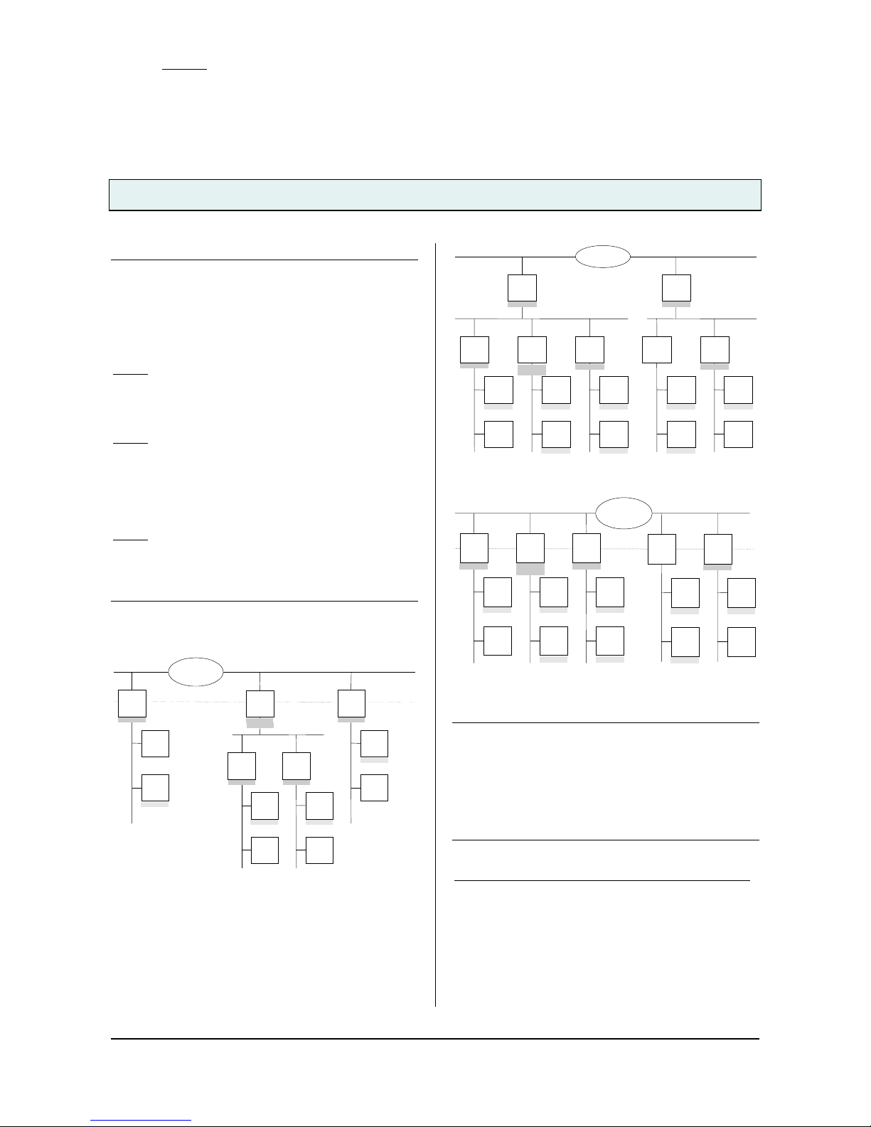
Note
When assigning the physical address take care that IP
Router and line couplers receive the topologically correct
physical address (Fig. 1, IP Router as area coupler and
li ne coupler).
Adhere to these rules:
Rule 1
:
In general an IP Router is used as a line coupler or an
area coupler. The physical address has the format x.y.0,
with x=1…15, y=1…15.
Rule 2:
If an IP Router is applied as an area coupler with the
physical address x.0.0 then no other IP Router with the
line coupler address x.y.0 (y=1…15) shall be placed
topologically „below“ this IP Router (Fig. 2, IP Router
N 146 as area coupler).
Rule 3
:
If an IP Router is applied as a line coupler (e.g. with
physical address 1.2.0) then no other IP Router shall be
used with a superior area coupler address (e.g. 1.0.0) in
this installation (Fig. 3, IP Router N 146 as line coupler).
Line
Coupler
2.1.0
Line
Coupler
2.2.0
Device
1.1.1
Device
1.1.2
Device
2.1.1
Device
2.1.2
Device
2.2.1
Device
2.2.2
4/1/1
4/1/1
5/5/1
Main Line 2
4/1/1
IP Network
EIBnet/IP
Router
1.1.0
EIBnet/IP
Router
2.0.0
IP
KNX
Device
3.3.1
Device
3.3.2
EIBnetIP
Router
3.3.0
4/1/1
4/1/1
5/5/1
5/5/1
5/5/1
5/5/1
Figure 1. IP Router as area and line coupler
EIBnet/IP
Router
1.0.0
IP Network
EIBnet /IP
Router
2.0.0
Main Line 1 Main Line 2
Line
Coupler
1.1.0
Line
Coupler
1.2.0
Line
Coupler
1.3.0
Line
Coupler
2.1.0
Line
Coupler
2.2.0
Device
1.1.1
Device
1.1.2
Device
1.2.1
Device
1.2.2
Device
1.3.1
Device
1.3.2
Device
2.1.1
Device
2.1.2
Device
2.2.1
Device
2.2.2
4/1/1
4/1/1
4/1/15/2/1
5/2/1
4/1/1
4/1/1
4/1/1 4/1/1
4/1/1
5/2/1
5/2/1
5/2/1
6/3/1
6/3/1
IP Network
Figure 2. IP Router as area coupler
Device
1.1.1
Device
1.1.2
Device
1.2.1
Device
1.2.2
Device
1.3.1
Device
1.3.2
Device
2.1.1
Device
2.1.2
Device
2.2.1
Device
2.2.2
4/1/1
4/1/1
4/1/1
5/2/1
5/2/1
4/1/1 4/1/1
4/1/1
5/2/1
5/2/1
5/2/1
6/3/1
6/3/1
IP Network
EIBnet/IP
Router
2.2.0
EIBnet/IP
Router
2.1.0
EIBnet/IP
Router
1.1.0
EIBnet/IP
Router
1.2.0
EIBnet/IP
Router
1.3.0
IP
KNX
Figure 3. IP Router as line coupler
Note
Smooth operation of the IP Router as line coupler or
back-bone coupler using KNXnet/IP Routing requires
LAN network components that support IP multicasting.
In particular, network / LAN routers must be configurable
respectively configured to forward IP multicast
datagrams.
The IP multicast address 224.0.23.12 was specifically
reserved for KNXnet/IP internationally for this purpose.
IP Router as interface to the bus (KNXnet/IP Tunneling)
A direct connection between a networked PC and the
bus can be established via a data network and the IP
Router. This allows for accessing the bus from any
access point in the data network.
The IP Router N146/02 provides up to four KNXnet/IP
Tunneling connections, allowing for e.g. simultaneous
configuration with ETS3 and operation of a visualization.
Page 3

GAMMA instabus
Technical Product Information
March 2014
IP Router N146/02 5WG1 146-1AB02
Siemens AG N 146/02, 8 pages Technical Manual
Infrastructure & Cities Sector, Building Technologies
Control Products and S ystem s ã Siemens AG 2014 Update: http://www.siemens.com
P.O.Box 10 09 53, D-93009 Regensburg Subject to change without prior notice
2.11.1.13/3
Note
For stable communication via KNXnet/IP Tunneling the
IP Router must use a separate individual address for
each KNXnet/IP Tunneling connection. These additional
individual addresses must be different from the individual
address of the device and must not be used by any other
bus device. In ETS these individual addresses should be
reserved by proxy devices.
ObjectServer interface to the bus
A direct connection between a networked PC and the
bus can also be established via a data network and the
IP Router N146/02 using ObjectServer. ObjectServer
compared with KNXnet/IP Tunneling provides the
advantage that the communication can be maintained
even over network connecti ons with a transmission time
for the datagrams of over one second (e.g. satellite
connections).
Assignment of additional individual addresses
Additional individual addresses are either assigned with
ETS or alternatively without a tool automatically by the
device itself.
The automatic address assignment for KNXnet/IP
Tunneling and ObjectServer is started when the learning
button is pressed during normal operation for m ore than
5 seconds but less than 10 seconds. The programming
LED flashes during the address assignment process.
The device checks which individual addresses are
already used by other bus devices connected to the bus
line. These addresses are not used for the address
assignment.
By adding additional bus devices at a later time one or
more of the additional individual addresses could be
assigned twice. When during normal operation the
learning button is pressed for more than 10 seconds all
additional individual addresses in the IP Router N146/02
are reset to the default value (15.15.255) and the
programming LED is turned off.
IP a ddres s assi gnm ent
The IP address of the IP Router N146/02 is assigned
man uall y usi ng E TS, aut om ati cal ly by a DHCP ser ver i n
the IP network, or by the device itself (AutoIP).
Assignment of the IP address by a DHCP server allows
for changes of the device IP address without using ETS.
Configuration of the DHCP server may require the MAC
address, which is printed on the device. If a DHCP
server is not available the device assigns itself an IP
address (AutoIP).
Please consult your network administrator regarding
con figuration of the parameter s device I P address,
subnet mask, and DHCP.
Default factory settings
By default the KNXnet/IP Routing function is active.
Wh en two KNXnet/IP routers are connected with each
other via a cross-o ver cable or via a network h ub, bu s
telegrams are routed by the KNXnet/IP Router without
any configuration.
The IP Router ships with these default factory settings:
· Physical address of the IP Router:
15.15.0 (= FF00 hex)
· Filter group telegrams
· All bus telegrams are repeated in case of
transmission errors
· The IP Router acknowledges routed telegrams only
· Support for devices with mis-matching physical
address
· Route broadcast telegrams
· Monitor the bus line
· IP address assignment via DHCP
Behavior on bus voltage loss / recovery on the bus line
When the IP Router detects a loss of bus voltage on the
bus line, this error is saved and annunciated via
KNXnet/IP. When the IP R outer detects recovery of bus
voltage on the bus line, the error flag is deleted and the
resumption of bus voltage is annunciated via KNXnet/IP.
Application programs
The IP Router can be configured with ETS2 v12 or
higher.
It requires the application program "IP Router 001002".
Page 4

GAMMA instabus
Technical Product Information
March 2014
IP Router N146/02 5WG1 146-1AB02
Technical Manual N 146/02, 8 pages Siemens AG
Infrastructure & Cities Sector, Building Technologies
Update: http://www.siemens.com ã Siemens AG 2014 Control Products and Systems
Subject to change without prior notice P.O.Box 10 09 53, D-93009 Regensburg
2.11.1.13/4
Example of Operation
L
N
Bus
AC/DC 24 V
Spannungsversorgung
N 125 / 21
Linie 2
Linie 3
Lini e 4
Linie 1
IP Router
N 146/02
Ethernet
TCP / IP
Hub
Example of Operation 1 with external auxiliary power
supply
LN
Bus
DV 29 V
Spannungsversorgung
N 125 / 21
Linie 2
Linie 3
Linie 4
Linie 1
IP Router
N 146/02
Ethernet
TCP / IP
Hub
Example of Operation 2 with auxiliary power supply from
unchoked bus power supply
Installation Instructions
· The device may be used for permanent interior
installati ons i n dry locations within distrib ution boards
or small casings with DIN rail EN 60715-TH35-7,5.
V
WARNING
· The device must be mounted and commissioned by an
authorised electrician.
· Free DIN rail areas with sticked-in data rails must be
covered with covers, order no. 5WG1 192-8AA01.
· T h e pr ev ai l i n g saf ety rul es mu st b e heeded .
· The device must not be opened.
· For planning and construction of electric installations,
the relevant guidelines, regulations and standards of
the respective country are to be considered.
Technical Specifications
Net work comm unic ation
· Ethernet:
10BaseT (10 Mbit/s)
· Supported Internet Protocols:
ARP, ICMP, IGMP, UDP/IP, DHCP, AutoIP
· KNXnet/IP according to KNX System Specification:
Core, Routing, Tunneling, Device Managem ent
Rated voltage
· Bus: DC 24V (DC 21...30V)
· Auxiliary power supply:
from “Power over Ethernet” DC 48V (acc. to IEEE
802.3af)
max. 0,8W
altern atively fr om
external power supply AC/DC 24V
(AC 12…24V, DC 12...30V)
max. 1,7W (57mA @ DC 24V)
Page 5

GAMMA instabus
Technical Product Information
March 2014
IP Router N146/02 5WG1 146-1AB02
Siemens AG N 146/02, 8 pages Technical Manual
Infrastructure & Cities Sector, Building Technologies
Control Products and S ystem s ã Siemens AG 2014 Update: http://www.siemens.com
P.O.Box 10 09 53, D-93009 Regensburg Subject to change without prior notice
2.11.1.13/5
Power supply
· Bus voltage: via KNX/EIB bus line
· Operating voltage:
from “P ower over Ethernet” according to IEEE 802.3af,
nominal voltage DC 48V
alternatively, from external SELV power supply AC/DC
24V nominal,
permissible input voltage range:
AC 12...24V, DC 12 ... 30 V
· Rec omm en ded power su ppli es:
DC 29V (before choke) from KNX/EIB power supply
N125/21
Power supply unit 4AC2 402
Primary voltage AC 85-265V / DC 85-300V,
Secondary voltage DC 24V, 2MU width
safety transformers 4AC3 724-0
Primary voltage 230V AC Secondary voltage AC 12V,
3MU width
safety transformers 4AC3 740-1
Primary voltage 230V AC Secondary voltage AC 12V
24V, 5MU width
V
CAUTION
It is recommended to use the e xternal safety extra low
voltage power supply for the IP Router N146/02 only.
Power usage
· From the bus line: m ax. 10mA @ DC 29V
· From the auxiliary power supply: max. 1,7 W
(57mA @ DC 24V)
Control elements
1 learning button:
for switching between normal operating mode and
addressing mode
Display elements
· 1 green LED: device ready (ON)
· 1 yellow LED: Communication on bus line
· 1 green LED: Ethernet Link Signal available (Lk)
· 1 yellow LED: Receiving data from Ethernet (Rx)
· 1 red LED: Transmitting data to Ethernet (Tx)
· 1 red LED: for monitoring bus voltage and displaying
mode, selected with the learning button
Connections
· bus line: screwless bus connection block (red-black)
0,6...0,8 mm Ø single core
remove approx. 5mm of isolation
· Ethernet / IP network: RJ45 socket
· auxiliar y power:
screwless extra low voltage terminal (yellow-white)
Æ 0,6 ... 0,8 mm Ø single core
remove approx. 5mm of isolation
Physical specifications
· housing: plastic
· N- s yst em DI N-r ai l mou nted dev i c e,
width: 2 SUs (1SU = 18mm)
· Installation: Snap-on mounting on DIN rail
EN 60715-TH35-7.50
· weight: approx. 105g
· Fire load: approx. 2840 kJ ± 10 %
Electrical safety
· degree of pollution (according to IEC 60664-1): 2
· prot ection (according to EN 60529): IP 20
· prot ection class (according to IEC 61140): III
· overvoltage class (according to IEC 60664-1): III
· bus: safety extra low voltage SELV DC 24 V
· t he dev i c e com pl i es wi th E N 50 09 0- 2- 2
Electromagnetic compatibility
complies with
EN 61000-6-2 and EN 61000-6-3 and EN 50090-2-2
Environmental specifications
· climatic conditions: EN 50090-2-2
· ambi en t temp erat ur e opera ting: - 5 . .. + 45 °C
· storage tem perature: - 25 ... + 70° C
· relative humidity (non-condensing): 5 % to 93 %
Markings
KNX, EIB, CE
CE mark
complies with th e EMC regulations (residential and
functional buildings), and low voltage regulations
Page 6

GAMMA instabus
Technical Product Information
March 2014
IP Router N146/02 5WG1 146-1AB02
Technical Manual N 146/02, 8 pages Siemens AG
Infrastructure & Cities Sector, Building Technologies
Update: http://www.siemens.com ã Siemens AG 2014 Control Products and Systems
Subject to change without prior notice P.O.Box 10 09 53, D-93009 Regensburg
2.11.1.13/6
Location and Function of the Display and
Operator Elements
A1
A2
A3
A4
A8
A9
A7
A6
A5
A10
Figure 4: Location of the display and operator elements
A1 LED red: indicating normal operating mode
(LED off) and addressing mode (LED on)
A2 learning button for switching between normal
operating mode and addressing mode for receiving
the physical address
A3 LED green: Operation
A4 LED yellow: data transmission on bus line (Line)
A5 LED green: Ethernet Link signal (Lk)
A6 LED yellow : Eth ernet Receiv e si gnal (Rx)
A7 LED red: Ethernet Transmit signal (Tx)
Note
When the learning button (A2) is pressed, this LED
signals for 10 seconds how the IP address was
ass igned to the d evic e:
1x flashing: fixed IP address
2x flashing: DHCP
3x flashing: AutoIP
A8 extra low-voltage bus terminals (red-black)
A9 extra low-voltage terminals (yellow-white)
A10 RJ45 socket for data network cable
Mounting and Wiring
General description
The N-system DIN-rail device can be installed in
N-system distribution boards, surface or flush mounted,
or on any DIN rail complying with EN 60715 -TH35-7, 5.
The connection to the bus line is established via the bus
connector terminal (red-black) on the top side .
The RJ45 socket on the device front side provides the
connection to the Ethernet-IP data network.
Mounting DIN-rail devices
(Figure 5)
- Slide the device (B1) onto the DIN-rail (B2) and
- swivel back the device until the slide clicks into place
audibly.
Dismounting DIN-rail devices (Figure 5)
- Remove all connected wires ,
- press down the slide (C3) with a screw-driver and
- swivel the device (C1) from the DIN-rail (C2).
B1
C1
C2
C3
B2
Figure 5: Mounting and dismounting a DIN-rail device
Slipping off bus connection blocks
(Figure 6)
- The bus connection block (D2) is situated on the top of
the device (D1).
- The bus connection block (D2) consists of two
components (D2.1 and D2.2) with four terminal
contacts each. Take care not to damage the two test
sockets (D2.3) by accidentally connecting them to the
bus cable or with the screw-driver (e.g. when
attempting to unplug the bus connection block).
- Carefully put the screw-driver to the wire-inserting slit
of the bus connection block's grey component and
pull the bus connection block (D2) from the device
(D1).
Slipping on bus connection blocks
(Figure 6)
- Slip the bus connection block onto the guide slot and
- press the bus connection block (D2) down to the stop.
Page 7

GAMMA instabus
Technical Product Information
March 2014
IP Router N146/02 5WG1 146-1AB02
Siemens AG N 146/02, 8 pages Technical Manual
Infrastructure & Cities Sector, Building Technologies
Control Products and S ystem s ã Siemens AG 2014 Update: http://www.siemens.com
P.O.Box 10 09 53, D-93009 Regensburg Subject to change without prior notice
2.11.1.13/7
Connecting bus cables
(Figure 6)
- The bus connection block (D2) can be used with single
core conductors Ø 0,6 ... 0,8 mm.
- Remove approx. 5 mm of insulation from the
conductor (D2.4) and plug it into the bus connection
block (D2) (red = +, black = -).
Disconnecting bus cables
(Figure 6)
- Unplug the bus connection block (E1) and remove the
bus cable conductor (E1.4) while simultaneously
wigg ling it.
D2
D
D2
D2.
4
5 mm
D2
D2.4
D2.1
D2.2
D2
D2.3
Figure 6: Connecting and disconnecting bus wires
Slipping off / on auxiliary power connection block
- Follow the instructions for the bus connection block
when slipping off/on the auxiliary power connection
block.
Dimension Diagram
Dimensions in mm
b
90
44
55
45
b = 2 SU
1 Standard unit (SU) = 18 mm
D1
Page 8

GAMMA instabus
Technical Product Information
March 2014
IP Router N146/02 5WG1 146-1AB02
Technical Manual N 146/02, 8 pages Siemens AG
Infrastructure & Cities Sector, Building Technologies
Update: http://www.siemens.com ã Siemens AG 2014 Control Products and Systems
Subject to change without prior notice P.O.Box 10 09 53, D-93009 Regensburg
2.11.1.13/8
Supported Software
Here is a list of software supporting the IP Router N 146.
Com Brid ge Studio
IPAS GmbH
Grabenstr 149 a
47057 Duisburg
Germany
[http://www.ipas-products.com]
Visualization, Database interface,
Notification via email, OPC Server
ComBridge Studio is a visualization software that can
use the IP Interface N148/22, the IP Router N146, the IP
Controller N350E and the IP Viewer N151 as interface to
KNX/EIB. Find more informatio n in the GAMMA catalog
or at the above listed web site.
ETS 3
KNX Association
De Kl eetlaan 5, Bus 11
B-1831 Brussels-Diegem
Belgium
[http :/ /www.knx.org]
Configuration of bus installations via existing
data net works (ETS 3.0c or higher)
An KNXnet/IP driver is available for ETS3. When this
driver is installed ETS3 may use the IP Interface
N148/21, the IP Router N146, the IP Controller N350E
and the IP Viewer N151 as interfaces to the bus just like
a standard RS232 or USB serial interface. This function
includes download of device configuration via the bus
and the group monitor function of ETS3.
Note
The KNX Association has decided that IP routers shall
not implement support for busmonitoring.
The ETS3 driver currently does not support local
download.
Note
After installing the ETS3 driver and selecting the
IP Interface or the IP Router as communication interface
a windows message may pop up announcing that a
"Class" is unknown.
In this case install the Microsoft .Net Framework that you
can download from the Microsoft software update site
(file size: approx. 25MB).
General Notes
· The operating instructions must be handed over to the
client.
· Any faulty device is to be sent together with a return
delivery note of the local Siemens office.
· For any technical questions, please consult:
' +49 (911) 895-7222
7 +49 (911) 895-7223
* support.automation@siemens.com
www.siemens.com/automation/support-request
 Loading...