

Page 1
GAMMA instabus
IP Router N 146
IP Router N 146 5WG1 146-1AB01
Bedien- und Montageanleitung
Operating and Mounting Instructions
Stand: Januar 2007
Issued: January 2007
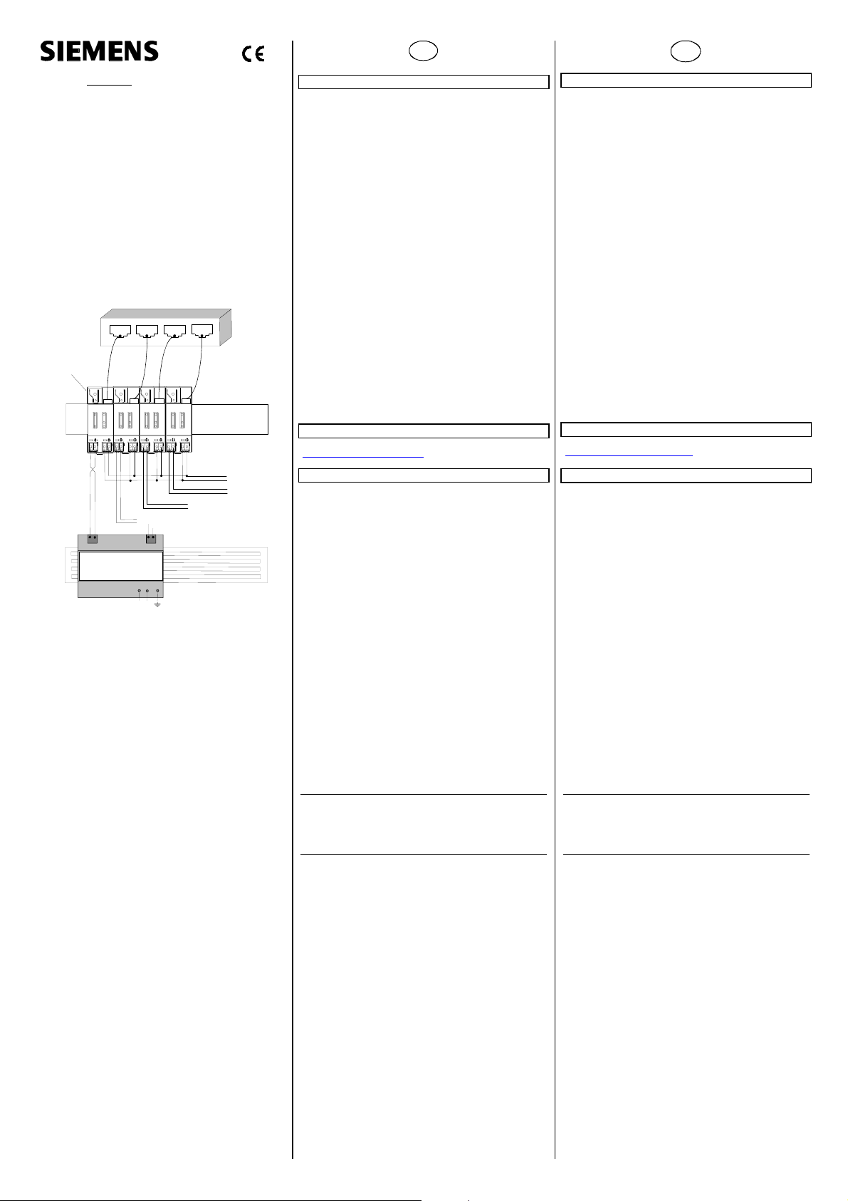
IP Router
N 146
Linie 1
Bus
Spannungsv ersorgung
N 125 / 21
Bild 1 / figure 1
Linie 2
N
L
2515154150 DS 02
Linie 3
Ethernet
TCP / IP
Hub
AC/DC 24 V
Linie 4
Produkt- und Funktionsbeschreibung
Der IP Router N146 ist ein Reiheneinbaugerät zum Einbau in
Verteilungen. Das Gerät verbindet EIB Linien miteinander über
Datennetzwerke unter Nutzung des Internet Protokolls (IP).
Zugleich bietet dieses Gerät die Kommunikation von EIB Geräten mit PC’s oder anderen Datenverarbeitungsgeräten.
Die Verbindung zum EIB wird über eine Busanschlussklemme
hergestellt. Die Verbindung zum Datennetzwerk (IP über
10BaseT) erfolgt über eine RJ45 Buchse.
Für den Betrieb benötigt der IP Router zusätzlich AC/DC 24 V,
die über einen zweiten Klemmenblock eingespeist werden. Die
Stromversorgung des IP Routers erfolgt über diesen Betriebsspannungsanschluss. Dies ermöglicht das Melden von Busspannungsausfall über das Datennetzwerk.
Der IP Router nutzt den EIBnet/IP Standard, so dass über ein IP
Netzwerk EIB Telegramme zwischen Linien weitergeleitet werden können und zugleich der Buszugriff von einem PC erfolgen
kann.
Der IP Router N 146 verbindet über ein Datennetzwerk zwei getrennte EIB-Buslinien datenmäßig miteinander, trennt sie jedoch galvanisch voneinander. Dadurch kann jede Buslinie im lokalen Betrieb unabhängig von anderen Linien betrieben werden.
Der N 146 ist einsetzbar als Linienkoppler oder Bereichskoppler, sowohl in bestehenden EIB-Netzwerken als auch in neuen
KNX EIB-Netzwerken. Er enthält Filtertabellen, mit deren Hilfe
bestimmte Bustelegramme von oder zur Buslinie entweder gesperrt oder durchgeschleust werden und trägt so zur Verringerung der Busbelastung bei. Die Filtertabelle wird von der ETS
(EIB Tool Software) bei Parametrierung und Inbetriebnahme der
Anlage automatisch erstellt.
Weitere Informationen
http://www.siemens.de/gamma
Technische Daten
Netzwerkkommunikation
• Ethernet:
10BaseT (10 Mbit/s)
• Unterstützte Internet Protokolle:
ARP, ICMP, IGMP, UDP/IP, DHCP
• EIBnet/IP gemäß Konnex System Spezifikation:
Core, Routing, Tunneling, Device Management
Bemessungsspannung
• Bus: DC 24V (DC 21...30V)
• Hilfsspannungsversorgung:
AC/DC 24V (AC/DC 12...30V)
Spannungsversorgung
• Busspannung: erfolgt über die EIB Buslinie
• Betriebsspannung:
aus externer Sicherheitskleinspannung AC/DC 24V nominal,
zulässiger Eingangsspannungsbereich:
AC/DC 12 ... 30 V
• Empfohlene Spannungsversorgungen:
–Klingeltransformator 4AC3 108, AC 230V / AC 2x12V (primär / sekundär), 2x0,33A, 2TE breit
–Klingeltransformator 4AC3 116, AC 230V / AC 2x12V (primär / sekundär), 2x0,0,67A, 2TE breit
–Klingeltransformator 4AC3 140, AC 230V / AC 2x12V (primär / sekundär), 2x1,67A, 3TE breit
V
• Die externe Sicherheitskleinspannung wird durch das Gerät
• Es wird empfohlen, die externe Kleinspannungsversorgung
Stromaufnahme
• aus der Buslinie: max. 10mA bei DC 29V
• aus der Hilfsspannungsversorgung: max. 800mW
Anschlüsse
• Linie: Busklemme (schwarz-rot), schraubenlos
• Ethernet / IP Netzwerk: RJ45 Buchse
• Spannungsversorgung:
Mechanische Daten
• Abmessungen: Reiheneinbaugerät im N-Maß,
• Gewicht: 100g
Elektrische Sicherheit
• Schutzart (nach EN 60529): IP 20
Umweltbedingungen
• Umgebungstemperatur im Betrieb: - 5 ... + 45 °C
• Lagertemperatur: - 25 ... + 70 °C
• rel. Feuchte (nicht kondensierend): 5 % bis 93 %
VORSICHT
mit dem Potential des LAN verbunden. Damit besteht keine
Isolation mehr zur Erde, wenn der LAN-Schirm geerdet wird.
nur für den IP Router N146 zu verwenden.
(25mA bei DC 24V)
0,6...0,8mm Ø eindrähtig
Abisolierlänge 5mm
Busklemme (gelb-weiss), schraubenlos
0,6...0,8mm Ø eindrähtig
Abisolierlänge 5mm
Breite 2 TE (1 TE = 18 mm)
D
Seite 1 von 2
GB
Product and Applications Description
The IP Router N146 is a DIN rail mounted device.
The device connects EIB lines via data networks using the
Internet Protocol (IP). Also this device offers communication of
EIB devices with PC’s or other data processing equipment.
The physical connection to the EIB is established via a bus
connector terminal block. For connection to the data network
(IP via 10BaseT) the device contains an RJ45 socket.
To operate the IP Router requires AC/DC 24 V, which is
provided via a second terminal block. The IP Router is powered
via this operating voltage terminal connector. This allows the IP
Router to send a bus voltage failure notification onto the data
network.
The IP Router implements the EIBnet/IP standard for routing of
EIB telegrams between lines and for concurrent access to the
bus line from any PC.
The IP Router N146 logically connects EIB bus lines by transmitting EIB telegrams between them via a data network but
separates them galvanically. This allows to run each bus line independently from other bus lines.
The N146 can be used as line coupler or area coupler in existing
EIB networks as well as in new KNX EIB networks. The N146
holds a filter table determining, which bus telegrams are
transmitted or blocked from or to the bus line thus reducing the
bus load. The filter table is automatically generated by the ETS
(EIB Tool Software) during configuration and start-up of the system.
Additional Information
http://www.siemens.com/gamma
Technical Specifications
Network communication
• Ethernet:
10BaseT (10 Mbit/s)
• Supported Internet Protocols:
ARP, ICMP, IGMP, UDP/IP, DHCP
• EIBnet/IP according to Konnex System Specification:
Core, Routing, Tunneling, Device Management
Rated voltage
• Bus: DC 24V (DC 21...30V)
• Auxiliary power supply:
AC/DC 24V (AC/DC 12...30V)
Power supply
• Bus voltage: via EIB bus line
• Operating voltage:
from external SELV power supply AC/DC 24V nominal,
permissible input voltage range:
AC/DC 12 ... 30 V
• Recommended power supplies:
– door bell transformer 4AC3 108, AC 230V / AC 2x12V (primary / secondary), 2x0,33A, 2TE width
– door bell transformer 4AC3 116, AC 230V / AC 2x12V (primary / secondary), 2x0,0,67A, 2TE width
– door bell transformer 4AC3 140, AC 230V / AC 2x12V (primary / secondary), 2x1,67A, 3TE width
V
• The device connects the external safety extra low voltage
• It is recommended to use the external low voltage power
Power usage
• From the bus line: max. 10mA @ DC 29V
• From the auxiliary power supply: max. 800mW
Connections
• bus line:
• Ethernet / IP network: RJ45 socket
• auxiliary power: screwless extra low voltage terminal (yel-
Physical specifications
• N-system DIN-rail mounted device,
• weight: approx. 100g
Electrical safety
• protection (according to EN 60529): IP 20
Environmental specifications
• ambient temperature operating: - 5 ... + 45 °C
• storage temperature: - 25 ... + 70 ° C
• relative humidity (non-condensing): 5 % to 93 %
•
CAUTION
with the LAN potential. If the LAN shield is connected to
earth ground then the isolation to ground is lost.
supply for the IP Router N146 only.
(25mA @ DC 24V)
screwless bus connection block (red-black)
0,6...0,8 mm Ø single core
remove approx. 5mm of isolation
low-white) ∅ 0,6 ... 0,8 mm Ø single core
remove approx. 5mm of isolation
width: 2 SUs (1SU = 18mm)
page 1 of 2
Page 2
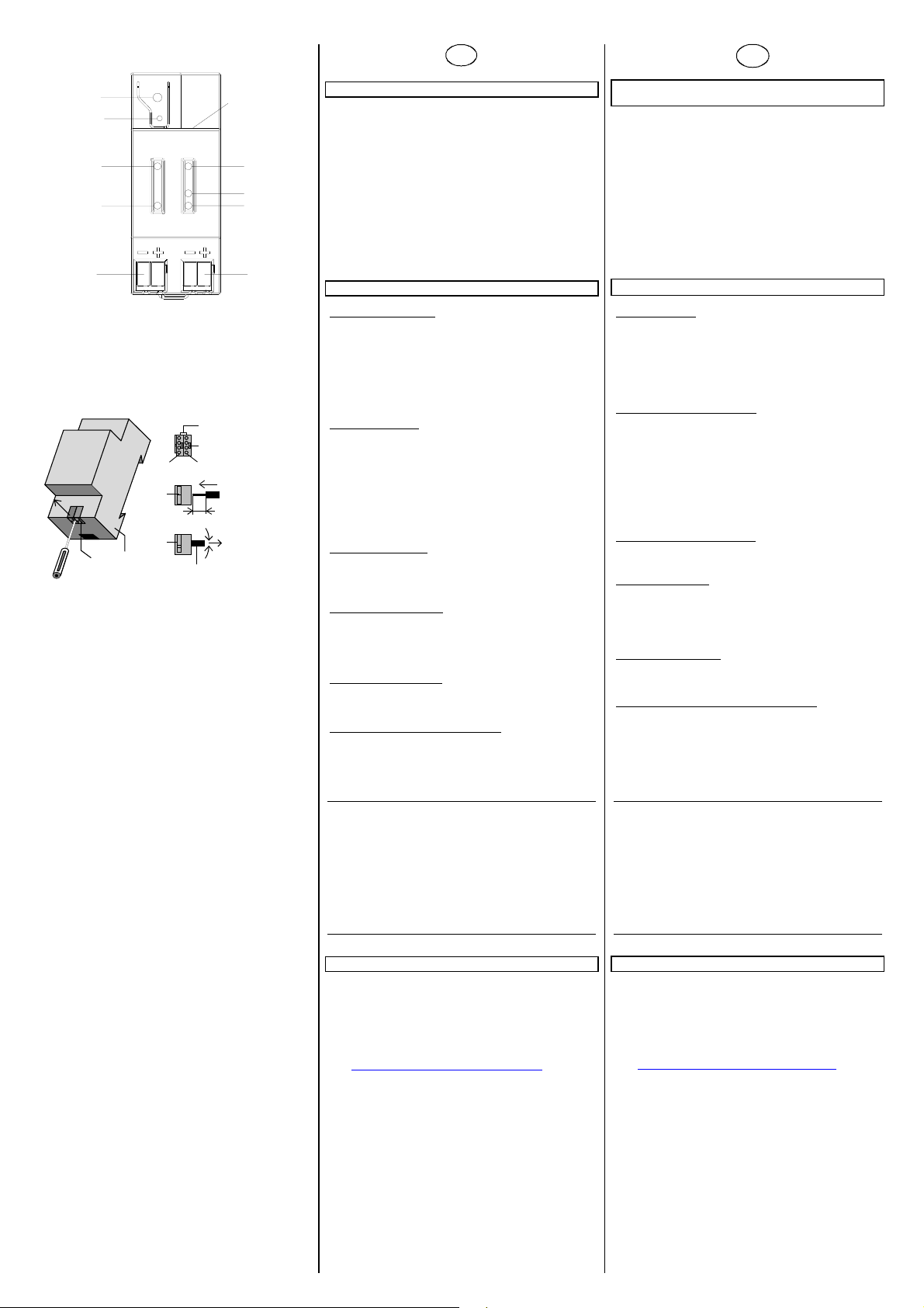
A1
A2
A3
A4
A8
Bild 2 / figure 2
D2
Bild 3 / figure 3
D
A10
A5
A6
A7
A9
D2
D2.3
D2.2
D2.1
D2
D2.4
5 mm
D2
D
D2.4
2515154150 DS 02
Lage- und Funktion der Anzeige- und Bedienelemente
siehe Bild 2
A1 LED rot: zur Anzeige Normalmodus (LED=Aus) oder Ad-
ressiermodus (LED=Ein)
A2 Lerntaste zum Umschalten zwischen Normalmodus und
Adressiermodus zur Übernahme der physikalischen Ad-
resse
A3 LED grün: Betriebsbereit
A4 LED gelb: Datenempfang auf der Buslinie
A5 LED grün: Ethernet Link Signal (Lk)
A6 LED gelb: Ethernet Receive Signal (Rx)
A7 LED rot: Ethernet Transmit Signal (Tx)
A8 Busklemme für Buslinie
A9 Klemme für Betriebsspannung, AC/DC 24V
A10 RJ45 Buchse für Netzwerkkabel
Montage und Verdrahtung
Allgemeine Beschreibung
Das Reiheneinbaugerät im N-Maß kann in Niederspannungsverteilern (Auf-Putz oder Unter-Putz) und überall dort eingesetzt
werden, wo Hutschienen nach EN 60715-TH35-7,5 vorhanden
sind.
Die Verbindung mit der Buslinie erfolgt über eine oben liegende
Busklemme.
Zur Verbindung mit dem Ethernet-IP Datennetzwerk verfügt das
Gerät über eine RJ45 Buchse auf der Gerätefrontseite.
Busklemme abziehen (Bild 3)
Die Busklemme (Klemmenblock) (D2) besteht aus zwei Teilen
(D2.1, D2.2) mit je vier Klemmkontakten. Es ist darauf zu achten, daß die beiden Prüfbuchsen (D2.3) weder mit dem Busleiter (versehentlicher Steckversuch) noch mit dem Schraubendreher (beim Versuch die Busklemme zu entfernen) beschädigt
werden.
Den Schraubendreher vorsichtig in den Drahteinführungsschlitz
des grauen Teils der Busklemme (D2.2) einführen und die Busklemme (D2) nach vorne aus dem Gerät (D1) herausziehen.
Busklemme aufstecken (Bild 3)
Die Busklemme in die Führungsnut stecken und
die Busklemme (D2) bis zum Anschlag nach hinten
drücken
Anschließen der Busleitung (Bild 3)
Die Busklemme (D2) ist für eindrähtige Leiter mit
0,6 ... 0,8 mm Ø geeignet.
Den Leiter (D2.4) ca. 5 mm abisolieren und in Klemme (D2)
stecken (rot = +, schwarz = -).
Abklemmen der Busleitung (Bild 3)
Die Busklemme (D2) abziehen und den Leiter (D2.4) der Buslei-
tung, bei gleichzeitigem Hin- und Herdrehen, herausziehen.
Spannungsklemme abziehen / aufstecken
Zum Abziehen und Aufstecken der Spannungsklemme ist wie
bei der Busklemme zu verfahren.
V
• Das Gerät darf nur von einer zugelassenen Elektrofachkraft
• Freie Hutschienenbereiche mit eingelegter Datenschiene
• Die geltenden Sicherheits- und Unfallverhütungsvorschriften
• Das Gerät darf nicht geöffnet werden.
• Bei der Planung und Errichtung von elektrischen Anlagen
Allgemeine Hinweise
• Die Bedienungsanleitung ist dem Kunden auszuhändigen.
• Ein defektes Gerät ist an die zuständige Geschäftsstelle der
• Bei zusätzlichen Fragen zum Produkt wenden Sie sich bitte
!+49 (180) 5050-222
! +49 (180) 5050-223
" www.siemens.de/automation/support-request
WARNUNG
installiert und in Betrieb genommen werden.
sind mit der Abdeckung 5WG1 192-8AA01
abzudecken.
sind zu beachten.
sind die einschlägigen Richtlinien, Vorschriften und Bestimmungen des jeweiligen Landes zu beachten.
Siemens AG zu senden.
an unseren Technical Support:
Seite 2 von 2
Location and Function of the Display and Operating Elements
See figure 2
A11 LED red: indicating normal operating mode
(LED off) and addressing mode (LED on)
A12 learning button for switching between normal
operating mode and addressing mode for receiving the
physical address
A13 LED green: Operation
A14 LED yellow: data transmission on bus line (Line)
A15 LED green: Ethernet Link signal (Lk)
A16 LED yellow: Ethernet Receive signal (Rx)
A17 LED red: Ethernet Transmit signal (Tx)
A18 extra low-voltage bus terminals (red-black)
A19 extra low-voltage terminals (yellow-white)
A20 RJ45 socket for data network cable
Mounting and wiring
General description
The N-system DIN-rail device can be installed in
N-system distribution boards, surface or flush mounted, or on
any DIN rail complying with EN 60715-TH35-7,5.
The connection to the bus line is established via the bus connector terminal (red-black) on the top side.
The RJ45 socket on the device front side provides the connection to the Ethernet-IP data network.
Slipping off bus connection blocks
The bus connection block (D2) is situated on the top of the device (D1).
The bus connection block (D2) consists of two components
(D2.1 and D2.2) with four terminal contacts each. Take care not
to damage the two test sockets (D2.3) by accidentally connecting them to the bus cable or with the screw-driver (e.g. when
attempting to unplug the bus connection block).
Carefully put the screw-driver to the wire-inserting slit of the
bus connection block's grey component and pull the bus connection block (D2) from the device (D1).
Slipping on bus connection blocks
Slip the bus connection block onto the guide slot and
press the bus connection block (D2) down to the stop.
Connecting bus cables (Figure 3)
The bus connection block (D2) can be used with single core
conductors Ø 0,6 ... 0,8 mm.
Remove approx. 5 mm of insulation from the conductor (D2.4)
and plug it into the bus connection block (D2)
(red = +, black = -).
Disconnecting bus cables (Figure 3)
Unplug the bus connection block (E1) and remove the bus cable
conductor (E1.4) while simultaneously wiggling it.
Slipping off / on auxiliary power connection block
Follow the instructions for the bus connection block when slip-
ping off/on the auxiliary power connection block.
V WARNING
• The device must be mounted and commissioned by an
authorised electrician.
• Free DIN rail areas with sticked-in data rails must be
covered with covers, order no. 5WG1 192-8AA01.
• The prevailing safety rules must be heeded.
• The device must not be opened.
• For planning and construction of electric installations, the
relevant guidelines, regulations and standards of the respective country are to be considered.
General Notes
• The operating instructions must be handed over to the client.
• Any faulty device should be returned to the local Siemens
office.
• If you have further questions concerning the product please
contact our technical support.
! +49 (180) 5050-222
! +49 (180) 5050-223
" www.siemens.com/automation/support-request
GB
(Figure 3)
(Figure 3)
page 2 of 2
 Loading...