

Siemens MXG461B Series, MXG461B15-0.6, MXG461B15-3, MXG461B15-1.5, MXG461B25-8 Technical Instructions
...Page 1
Siemens Industry, Inc.
MXG461B Series
Technical Instructions
Document No. 125-4461
October 23, 2018
Modulating Control Valves with
Magnetic Actuators, Positioning
Control and Position Feedback for
Domestic Water
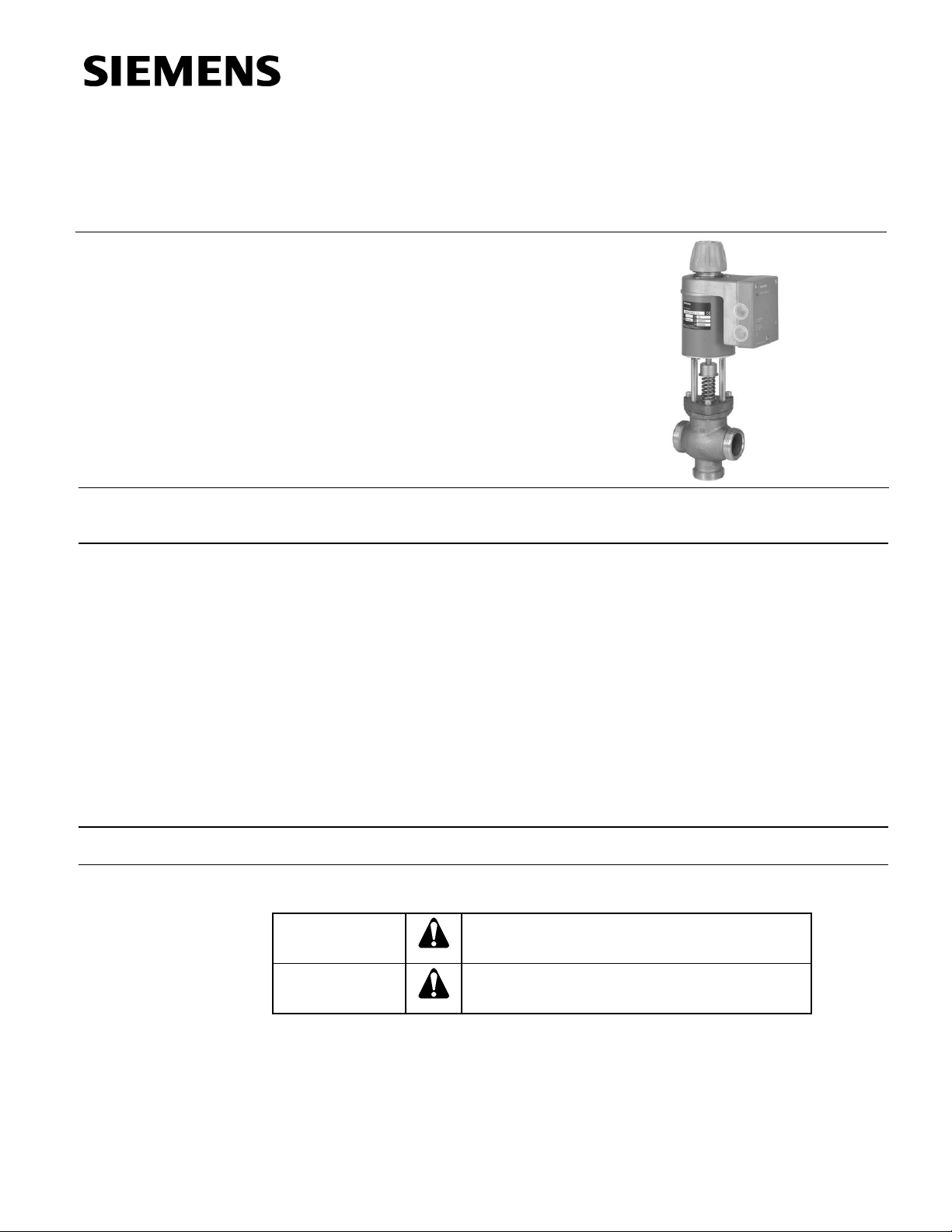
Description
Control valves with magnetic actuators, for modulating control of domestic water, cold
water and hot water systems.
Features
• Fast positioning time (< 2 seconds)
• Selectable valve characteristic: Equal percentage or linear
• Selectable standard interface: 0/2 to 10 Vdc or 0/4 to 20 mA
• High resolution (>1:1000)
• High rangeability
• Wear-free inductive stroke measurement
• Spring return A → AB closed when de-energized
• Positioning control and position feedback signal
• Low-friction, heavy-duty and maintenance-free
• Accepts 0 to 20 Vdc phase-cut control signal input
Product Numbers
See Table 1.
Warning/Caution
Notations
WARNING:
Personal injury or loss of life may occur if you do not
follow the procedures as specified.
CAUTION:
Equipment damage or loss of data may occur if you
do not follow the procedures as specified.
Page 2
Technical Instructions MXG461B Series Modulating Control Valve
Document Number 125-4461 with Magnetic Actuator
October 23, 2018
Page 2 Siemens Industry, Inc.
Application
The MX4G61B Series valves are through-port or mixing valves with magnetic
actuators. The actuator is equipped with an electronics module for positioning control
and position feedback. If the power is off, the valve control path A → AB is closed.
The short positioning time, high resolution and high rangeability make these valves
ideal for modulating control of domestic, hot and cold-water systems.
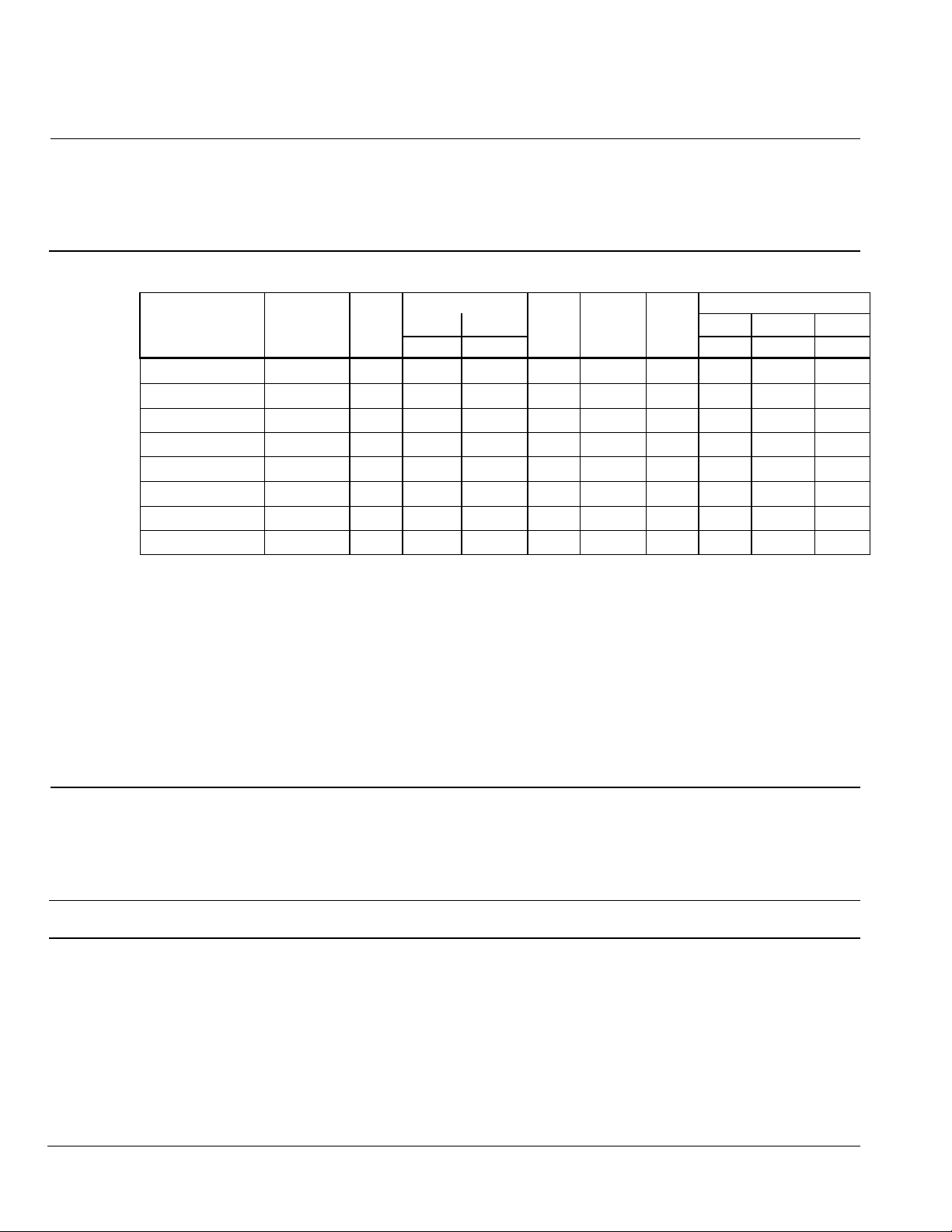
Table 1. Product Numbers.
Product
Number
Wire Gauge (AWG)
Line Size
Cv
ps
p
max
SNA
Pmed
IN
16
14
12
(in)
(psi)
(psi)
(VA)
(W)
Fuse
L (ft)
MXG461B15-0.6
1/2
0.7
145
70
33
15
3.15
130
215
360
MXG461B15-1.5
1/2
1.8
145
70
33
15
3.15
130
215
360
MXG461B15-3
1/2
3.5
145
70
33
15
3.15
130
215
360
MXG461B20-5
3/4
5.8
116
70
33
15
3.15
130
215
360
MXG461B25-8
1
9.3
102
40
33
15
3.15
130
215
360
MXG461B32-12
1-1/4
14
87
40
43
20
4
100
165
260
MXG461B40-20
1-1/2
23
87
40
43
20
4
100
165
260
MXG461B50-30
2
35
87
40
65
22
6.3
65
100
185
Key:
p
max
= Maximum permissible differential pressure across the valve's control path,
valid for the entire actuating range of the motorized valve (maximum
recommended operating differential pressure).
ps = Maximum permissible differential pressure at which the motorized valve will
close securely against the pressure (close-off pressure).
SNA = Nominal apparent power for selecting the transformer.
Pmed = Average true power.
IN = Slow fuse (mandatory).
Cv = Nominal flow rate of cold water [41°F to 86°F (5°C to 30°C)].
L = Maximum cable length. With four-wire connections the maximum
permissible length of the separate 14 AWG Cu signal cable is 656 feet
(200 m).
Ordering
• The valve body and magnetic actuator assemblies cannot be separated.
• The brass/bronze fittings are included.
• When placing an order, specify the quantity, product number and description.
Example: 1 MXG461B15-0.6 valve and 1 ASE12 Replacement Circuit Board
Accessory
ASE12 Replacement Circuit Board
Technical/
Mechanical Design
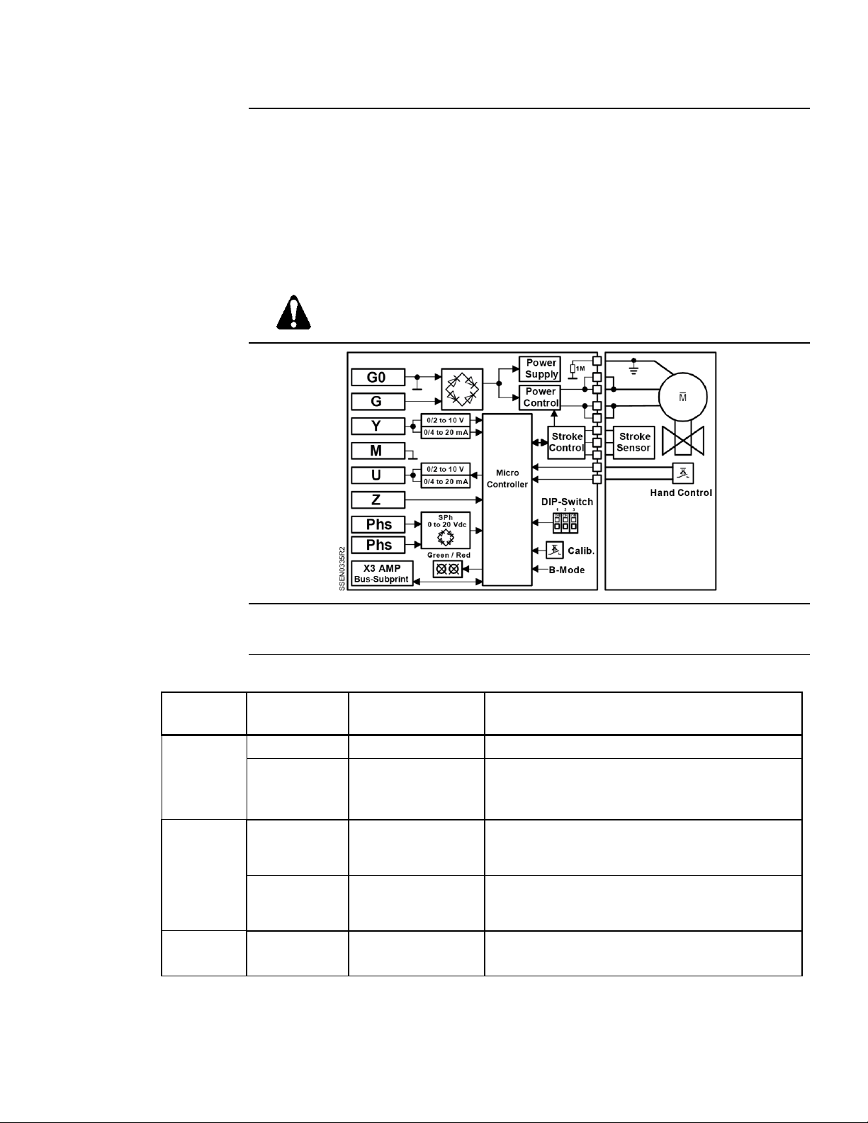
Operation Control
The electronics module converts the positioning signal to a phase-cut power signal,
which generates a magnetic field in the coil. This causes the armature to change its
position according to the interacting forces (magnetic field, counterspring, hydraulics,
etc.). The armature responds rapidly to any change in signal, transferring the
corresponding movement directly to the valve plug. This enables fast changes in load to
be corrected quickly and accurately.
The valve’s position is measured continuously. Any disturbance in the system is rapidly
corrected by the internal positioning controller, which ensures that the positioning signal
and the valve stroke are exactly proportional, and also delivers the position feedback
signal.
Page 3
MXG461B Series Modulating Control Valve Technical Instructions
with Magnetic Actuator Document Number 125-4461
October 23, 2018
Siemens Industry, Inc. Page 3
Control
The magnetic actuator can be driven by any controller with a 0/2 to 10 Vdc or 0/4 to
20 mA output signal.
To achieve optimum control performance, it is recommended to use a 4-wire connection
for the valve.
NOTE: When using a dc power supply a 4-wire connection is mandatory.
The controller’s signal ground terminal M must be connected to the valve’s terminal M.
Terminals M and G0 have the same potential and are internally interconnected in the
valve’s electronics.
CAUTION:
You must use a four-wire connection with Vdc power supply.
Basic Diagram
Spring Return Action
If the power or positioning signal is switched off or fails, the valve control path
(port A → AB) is automatically closed by the force of the spring.
Table 2. Indication of Operating State.
LED
Indication
Operating State,
Function
Remarks, Troubleshooting
Green
Lit
Control mode
Normal operation; everything OK.
Flashing
Calibration
In manual control
Wait until calibration is finished
(green or red LED will be lit).
Hand wheel in Man or Off position.
Red
Lit
Calibration error
Internal error
Recalibrate (bridge contacts behind the
calibration slot).
Replace electronics module.
Flashing
Mains fault
DC Supply -/+
Check electric main network (outside the
frequency or voltage range);
Vdc supply +/- connection polarity.
Both
Dark
No power supply
Electronics faulty
Check electric main network, check wiring.
Replace electronics module.
Page 4

Technical Instructions MXG461B Series Modulating Control Valve
Document Number 125-4461 with Magnetic Actuator
October 23, 2018
Page 4 Siemens Industry, Inc.
Manual Adjustment
Press (a) and turn the hand wheel (b):
• clockwise (CW). Control path A → AB can be
mechanically opened to between 80% and 90%,
or
• counterclockwise (CCW). The actuator will be
switched off and the valve closed.
As soon as the hand wheel is pressed and turned,
neither the forced control signal Z, the input signal
Y, nor the phase-cut signal acts on the actuator.
The green LED will flash.
For automatic control, the hand wheel must be set
to the Auto position. The green LED will be lit.
Figure 1.
Calibration
If the electronics module is replaced or the actuator turned
through 180°, the valve’s electronics must be recalibrated. To
recalibrate, the hand wheel must be set to Auto.
The printed circuit board has a slot (see Figure 2). Calibrate by
bridging the contacts located behind the slot on the printed
circuit board, using a screwdriver. The valve will then travel
across the full stroke to store the end positions.
While calibration is in progress, the green LED will flash for
about 10 seconds (see Indication of Operating State).
Figure 2.
DIP Switches
Figure 3. Configuration DIP Switches.
DIP
Function
OFF (Default)
ON
Remarks
1
ON
OFF
Voltage or current
input
[ V ]
[ mA ]
Assignment of
terminal Y:
Voltage or current
2
ON
OFF
Correcting span
Terminals Y and U
0 to 10 Vdc,
0 to 20 mA
2 to 10 Vdc,
4 to 20 mA
Offset settings of input
and output
3
ON
OFF
Characteristic
V
log
(equal
percentage)
V
lin
(linear)
–
Page 5

MXG461B Series Modulating Control Valve Technical Instructions
with Magnetic Actuator Document Number 125-4461
October 23, 2018
Siemens Industry, Inc. Page 5
DIP Switches, Continued
Figure 4. Assignment of Positioning
Signal Y: Voltage or Current.
.
Figure 5. Selection of Valve
Characteristic: Equal-Percentage or
Linear.
Figure 6. Assignment of Correcting
Span Y and U: 0 to 10 Vdc/0 to 20 mA or
2 to 10 Vdc/4 to 20 mA.
Output signal U (position feedback signal)
is dependent on the load resistance.
Above 500 ohm, it is automatically a
voltage signal; below 500 ohm a current
signal.
Forced Control Input
Transfer
Connections
Figure 7.
If terminal Z for the forced control input is:
− not connected, the valve will follow the Y-signal or the phase-cut signal.
− connected to G, the valve will fully open via control path A → AB.
− connected to G0, the valve will close via control path A → AB.
Signal Priority
1. Hand wheel position Man or Off
2. Forced control signal Z
3. Phase-cut signal
4. Signal input Y
Page 6

Technical Instructions MXG461B Series Modulating Control Valve
Document Number 125-4461 with Magnetic Actuator
October 23, 2018
Page 6 Siemens Industry, Inc.
Valve Sizing
Characteristic
Figure 8. Equal Percentage.
Figure 9. Linear.
Installation Notes
• Installation instructions for the valve and terminal housing are enclosed with the
valve.
• Valves are supplied complete with brass/bronze fittings.
• The screwed valves are flat-faced to facilitate sealing with the gaskets supplied.
The use of sealing compounds, tape or hemp thread is not recommended.
• For electrical installation, see Wiring Diagrams.
CAUTION:
• Always disconnect the power before fitting or removing the terminal
housing. The terminal housing is calibrated and matched to the
actuator and should be replaced only by qualified personnel.
• Use the valve only as a mixing or straight-through valve, not as a
diverting valve. Note the flow direction.
• Do not allow the surface temperature of the actuator to fall below the
dew point temperature of the surrounding air (causing condensation).
If necessary, insulate the valve. Do not insulate the actuator.
Use in Straight-through
Applications
Only three-way valves are supplied. These may
be used as straight-through valves by closing off
port B with the accessories supplied (nut, cover
and gasket).
Figure 10. Straight-through
Application.
Mounting Position
Vertical to horizontal mounting:
Do not mount the valve below the horizontal.
Figure 11. Acceptable Mounting
Positions.
Page 7

MXG461B Series Modulating Control Valve Technical Instructions
with Magnetic Actuator Document Number 125-4461
October 23, 2018
Siemens Industry, Inc. Page 7
Specification s
Electrical
Low-voltage use only Class 2 (SELV, PELV)
24 Vac
Operating voltage 24 Vac ± 20%
Frequency 45 to 65 Hz
Typical power consumption See Table 1 P
med
Standby <1 W (valve fully closed)
Nominal apparent power See Table 1, SNA
Suitable fuse Slow, see Table 1, IN
24 Vdc
Operating voltage 20 to 30 Vdc
Current draw 0.5A/4A (maximum)
Functional data, actuator
Input
Positioning signal Y 0/2 to 10 Vdc or 0/4 to 20 mA, or
0 to 20 Vdc Phs phase cut
Impedance 0/2 to 10Vdc 100K ohm//5nF (load < 0.1mA)
0/4 to 20 mA 240 ohm//5nF
Forced control
Impedance 22K ohm
Closing the valve (Z connected to G0) <1 Vac; <0.8 Vdc
Opening the valve (Z connected to G0) >6 Vac; >5 Vdc
No function (Z not wired) Phase-cut or positioning signal Y
active
Output
Position feedback signal U voltage 0/2 to 10 Vdc; load resistance > 500Ω
current 0/4 to 20 mA; load resistance < 500Ω
Stroke measurement Inductive
Nonlinearity +3% of end value
Functional data, valve
Nominal pressure ANSI 125 (PN 16)
Operating pressure p
e
max
1)
232 psi (16 bar)
Pressure differential p
v
max See Table 1
Leakage at A→ AB max. 0.05% Cv
p = 14.5 psi (1 bar) B→ AB < 0.2% Cv depending on
operating conditions
Permissible media Drinking water, cooling, cold and hot
water, water with anti-freeze
Water temperature –4°F to 266°F (–20°C to 130°C)
Valve characteristic 2) Equal percentage or linear, optimized
near the closing point
Resolution H/H100 1 : 1000 (H = Stroke)
Type of operation Modulating
Position when de-energized A → AB closed
Orientation: Upright to horizontal
Positioning time <2 seconds
Materials
Valve body Red bronze (CC499K)
Cover flange Red bronze (CC499K)
Seat/Inner valve Stainless Steel
Valve stem seal EPDM (O-ring)
1. Tested at 1.5 × PN (24 bar), similar to DIN 3230-3
2. Can be selected via DIP switch.
Page 8

Technical Instructions MXG461B Series Modulating Control Valve
Document Number 125-4461 with Magnetic Actuator
October 23, 2018
Page 8 Siemens Industry, Inc.
Specifications,
Continued
Pipe connections
Screwed fittings Bronze/brass
Electrical connections
Cable entries 2 × Ø 20.5 mm (for M20)
Connection terminals Screw terminals for up to 12 AWG wires
Min. cross-sectional area 1) 0.75 mm2
Max. cable length See Table 1, 9 (AWG)
Ambient conditions
Temperature
Operation and storage 23°F to 113°F (-5°C to 45°C)
Transport -13°F to 158°F (-25°C to 70°C)
Humidity 5 to 95% rh (non-condensing)
Agency approvals
Degree of protection IP31 to EN60529
Conforms to CE requirements CA2T4461.1
UL 873
Certified to Canadian standard C22.2 No. 24
C-Tick N-474
PED 2014/68/EU
DVGW-Reg.-Nr. DW-6340BR0230
(EU potable water standard)
Miscellaneous
Weight See Figure 15
Dimensions See Figure 15
Connection
Terminals
WARNING:
If the controller and the valve receive their power supply from separate
sources, the valve transformer must not be grounded on the secondary
side.
A four-wire connection is mandatory with DC power supply.
Controllers with:
0 to 10 Vdc
2 to 10 Vdc
0 to 20 mA
4 to 20 mA
Figure 12.
1. In case of strong vibrations, use high-flex stranded wires.
Page 9

MXG461B Series Modulating Control Valve Technical Instructions
with Magnetic Actuator Document Number 125-4461
October 23, 2018
Siemens Industry, Inc. Page 9
Connection
Terminals,
Continued
Controllers with phase-cut
0 to 20 Vdc
Figure 13.
Application
Examples
This example shows only a schematic diagram, without installation-specific details.
CAUTION:
1. Use the valve only as a mixing or straight-through valve, not a
diverting valve. Note the direction of flow.
2. Ensure that adequate air venting is provided for the entire hydronic
system.
3. Select a non-return valve with minimum pressure loss for the
circulating pipes.
Key :
A Mixing circuit
B Mixing circuit with bypass
(underfloor heating system)
C Injection circuit
D Diverting circuit
E Injection circuit with throughport valve
Figure 14.
Service
In case of strong vibrations, use high-flex stranded wires.
CAUTION:
Do not disassemble the valve and actuator combination. This assembly is
factory-calibrated and should only be replaced by qualified personnel.
• The low-friction and robust, maintenance-free design makes regular servicing
unnecessary and ensures a long service life.
• The valve stem is sealed from external influences by a maintenance-free gland.
• If the red LED is lit, the electronics must be recalibrated or replaced.
• If required, the circuit board can be replaced. Order part number ASE12.
Page 10

Technical Instructions MXG461B Series Modulating Control Valve
Document Number 125-4461 with Magnetic Actuator
October 23, 2018
Information in this publication is based on current specifications. The company reserves the right to make changes in specifications and models as
design improvements are introduced. Product or company names mentioned herein may be the trademarks of their respective owners.
© 2018 Siemens Industry, Inc.
Siemens Industry, Inc.
Building Technologies Division
1000 Deerfield Parkway
Buffalo Grove, IL 60089-4513
USA
+1-847-215-1000
Your feedback is important to us. If you have
comments about this document, please send them to
SBT_technical.editor.us.sbt@siemens.com
Document No. 125-4461
Printed in the USA
Page 10
Dimensions
Figure 15. Dimensions in Inches (Millimeters).
NOTE: The screwed fittings and gaskets are supplied with these valves.
Product Number
DN
G
(in)
L1
L2
L3 H E
F W lb
(kg)
(mm)
(in)
MXG461B15-0.6
15
Rp ½
G1B
3.15
(80)
1.67
(42.5)
1.97
(50)
13.4
(340)
3.15
(80)
4.53
(115)
15.65
(7.1)
MXG461B15-1.5
15
Rp ½
G1B
3.15
(80)
1.67
(42.5)
1.97
(50)
13.4
(340)
3.15
(80)
4.53
(115)
16.09
(7.3)
MXG461B15-3
15
Rp ½
G1B
3.15
(80)
1.67
(42.5)
1.97
(50)
13.4
(340)
3.15
(80)
4.53
(115)
16.09
(7.3)
MXG461B20-5
20
Rp ¾
G1¼B
3.74
(95)
2.07
(52.5)
2.36
(60)
13.3
(339)
3.15
(80)
4.53
(115)
16.97
(7.7)
MXG461B25-8
25
Rp 1
G1½B
4.33
(110)
2.22
(56.5)
2.52
(64)
13.6
(346)
3.15
(80)
4.53
(115)
18.73
(8.5)
MXG461B32-12
32
Rp 1¼
G2B
4.92
(125)
2.66
(67.5)
2.95
(75)
15.12
(384)
3.94
(100)
4.92
(125)
28.22
(12.8)
MXG461B40-20
40
Rp 1½
G2¼B
5.51
(140)
3.17
(80.5)
3.66
(93)
15.79
(401)
3.94
(100)
4.92
(125)
32.19
(14.6)
MXG461B50-30
50
Rp 2
G2¾B
6.69
(170)
3.68
(93.5)
4.2
(108)
402
(15.83)
3.94
(100)
4.92
(125)
41.00
(18.6)
G: External thread G…B to ISO228/1
DN: Internal thread Rp to ISO7/1
Fittings to ISO 49/DIN 2950 (supplied complete with flange gaskets)
 Loading...