

Page 1
MULTIX TOP
Operator Manual
MULTIX TOP
Operator Manual
Rückenschild für Schuber A4 (50 hoch)
Schneiden auf: 205x50 (mm)
MULTIX TOP
Operator Manual
MULTIX TOP
Operator Manual
Page 2

Page 3

AXB1-150.620.01.01.02 AXB1-150.620.01.01.02 AXB1-150.620.01.01.02 AXB1-150.620.01.01.02
AXB1-150.620.01.01.02 AXB1-150.620.01.01.02 AXB1-150.620.01.01.02 AXB1-150.620.01.01.02
AXB1-150.620.01.01.02 AXB1-150.620.01.01.02 AXB1-150.620.01.01.02 AXB1-150.620.01.01.02
AXB1-150.620.01.01.02 AXB1-150.620.01.01.02 AXB1-150.620.01.01.02 AXB1-150.620.01.01.02
AXB1-150.620.01.01.02 AXB1-150.620.01.01.02 AXB1-150.620.01.01.02 AXB1-150.620.01.01.02
AXB1-150.620.01.01.02 AXB1-150.620.01.01.02 AXB1-150.620.01.01.02 AXB1-150.620.01.01.02
AXB1-150.620.01.01.02 AXB1-150.620.01.01.02 AXB1-150.620.01.01.02 AXB1-150.620.01.01.02
AXB1-150.620.01.01.02 AXB1-150.620.01.01.02 AXB1-150.620.01.01.02 AXB1-150.620.01.01.02
AXB1-150.620.01.01.02 AXB1-150.620.01.01.02 AXB1-150.620.01.01.02 AXB1-150.620.01.01.02
AXB1-150.620.01.01.02 AXB1-150.620.01.01.02 AXB1-150.620.01.01.02 AXB1-150.620.01.01.02
AXB1-150.620.01.01.02 AXB1-150.620.01.01.02 AXB1-150.620.01.01.02 AXB1-150.620.01.01.02
AXB1-150.620.01.01.02 AXB1-150.620.01.01.02 AXB1-150.620.01.01.02 AXB1-150.620.01.01.02
AXB1-150.620.01.01.02 AXB1-150.620.01.01.02 AXB1-150.620.01.01.02 AXB1-150.620.01.01.02
Page 4

Page 5

1
Current Information / Safety
System Overview / Operating Elements
System Operation / Radiography
Exposure Tables
2
3
4
5
6
7
Operator Manual
MULTIX TOP
© Siemens AG 2004
All rights reserved
VERTIX PRO/TOP Bucky Wall Unit
Generator
Accessories
8
9
10
11
12
13
Order No.: AXB1-150.620.01.01.02
08.2004
Siemens AG Siemens AG, Medical Solutions, AX
Wittelsbacher Platz 2 Siemensstraße 1
DE-80333 München DE-91301 Forchheim
Germany Germany
Contact information:
Phone: +49 9191 18-0
Internet: www.Medical.Siemens.com
Technical Description
14
15
Page 6
Please observe the
Safety Instructions
Order No.: RX0-000.621.01
These must be studied exactly before system start-up.
Important information from the
manufacturer
This product is provided with a CE marking in accordance with the
regulations stated in Appendix II of the Directive 93/42/EC of June
14, 1993 concerning medical products.
In accordance with Appendix IX of the Directive 93/42/EWG, this
product is assigned to class II b.
The CE marking applies only to medical products which have been
put on the market according to the above-mentioned EC Directive.
The product complies with the requirements of EMC classes B +
12dB.
Unauthorized changes to this product invalidate this declaration.
The original version of this manual was written in the German
language.
Page 7

Product description
Table of Contents
Operator Manual
Product description
Chapter: Description
General information ............................................................................................................5
Applications ................................................................................................................... 5
Variants ......................................................................................................................... 5
System configuration .......................................................................................................... 6
1. "Manual" system version ............................................................................................... 6
2. "Manual" system version with planigraphy ......................................................................... 7
3. "ACSS" system version ................................................................................................. 8
4. "ACSS" system version with planigraphy ........................................................................... 9
Possibilities of use ............................................................................................................ 10
Chapter: Overview
Standard Configuration ..................................................................................................... 11
MULTIX TOP ................................................................................................................ 11
MULTIX TOP P ............................................................................................................. 11
MULTIX TOP ACSS ....................................................................................................... 11
MULTIX TOP ACSS P .................................................................................................... 11
Extensions ........................................................................................................................ 12
Overall view ...................................................................................................................... 13
Edge protection on the patient table ................................................................................. 14
Chapter: Safety Information
General safety .................................................................................................................. 15
Collision and crushing zones ............................................................................................ 15
Switching on the system on the generator ...................................................................... 18
"Manual" system without ACSS automatic format collimation ................................................. 18
Only if ACSS automatic format collimation is installed ........................................................... 18
MULTIX TOP
AXB1-150.620.01.01.02 1
of 64
Page 8

Product description
Table of Contents
Red EMERGENCY STOP button ...................................................................................... 19
Red EMERGENCY SHUTDOWN button ........................................................................... 19
Blockage and fault indicators ............................................................................................ 20
Daily Checks ..................................................................................................................... 21
Before examinations ...................................................................................................... 21
During examinations ...................................................................................................... 21
Monthly Checks ................................................................................................................ 22
Legally required checks .................................................................................................... 22
Safety-relevant parts subject to wear ............................................................................... 22
Maintenance intervals ...................................................................................................... 23
Behavior in the case of functional disturbances ............................................................... 23
Cleaning the system ......................................................................................................... 23
Disinfection of the system ............................................................................................... 23
Chapter: Operating Elements
Operating elements for table movements ....................................................................... 25
Foot kick switch in the table base ..................................................................................... 25
Operating Elements for 3D Ceiling Support ..................................................................... 27
Operating elements and function displays on the control panel ...................................... 29
Operating elements ....................................................................................................... 29
Operating elements for 3D support and tube unit ........................................................ 29
Operating elements for moving the X-ray tube unit ...................................................... 30
Function displays ................................................................................................. 30
Operating elements for planigraphy (only with TOP P and TOP ACSS P) .......................... 32
Operating elements and function displays on the control panel with analog angle display
(only with MULTIX TOP) ................................................................................................... 33
Operating elements ....................................................................................................... 33
Operating elements for 3D support and tube unit ........................................................ 33
Operating elements for moving the X-ray tube unit ...................................................... 34
Function displays ................................................................................................. 34
Operator Manual
2
of 64 AXB1-150.620.01.01.02
Page 9

Product description
Table of Contents
Manual collimator ............................................................................................................. 35
Operating elements and displays ...................................................................................... 35
Front ................................................................................................................. 35
Bottom side ........................................................................................................ 36
Backside ............................................................................................................. 39
Changing the lamp on the collimator ................................................................................. 39
Operation .................................................................................................................... 43
Setting the format collimation ................................................................................. 43
Rotating the collimator about the central beam axis (up to ± 50°) ................................... 45
Rotating the collimator to the 0° stop position ............................................................ 47
Setting the prefiltration .......................................................................................... 48
ACSS Collimator ............................................................................................................... 49
Operating elements and displays ...................................................................................... 49
Front ................................................................................................................. 49
Display on the ACSS Collimator ............................................................................... 50
Bottom ............................................................................................................... 51
Backside ............................................................................................................. 53
Changing the collimator lamp .......................................................................................... 54
Operation .................................................................................................................... 55
Rotating the collimator about the central beam axis (max. up to ±45°) ............................. 55
Rotating the collimator into the 0° stop position .......................................................... 56
Indication of the collimator 0° stop position ................................................................ 56
Setting the prefiltration .......................................................................................... 57
Operating elements on the manual or ACSS cassette tray .............................................. 59
Brake handle ................................................................................................................ 60
Position of the brake handle ................................................................................... 60
Function of the brake handle ................................................................................... 60
Operating the brake handle .................................................................................... 60
Operating and display elements of the follow-up control (only with ACSS and ACSS P) . 61
Overall view ................................................................................................................. 61
Control panel and displays for ceiling support settings .......................................................... 62
Operating elements for motor-driven height adjustment (vertical) ................................... 62
Operating elements on the patient table ............................................................................ 63
Operating elements for MULTIX constant SID ............................................................ 63
MULTIX TOP
AXB1-150.620.01.01.02 3
of 64
Page 10

Product description
Table of Contents
Operator Manual
4
of 64 AXB1-150.620.01.01.02
Page 11

Product Description
Description
General information 0
This Operator Manual describes all system features of all system variants.
The complete system is described with all options and components that have
been released. Possible options have not been marked specially. Particular options or components may not be available for specific systems.
The quotation text of your order is the sole reference for the functional scope of
your system.
Applications 0
With your MULTIX TOP you have a Bucky table radiographic system with a 3D
ceiling support at a high technical level for hospital and medical practice.
The X-ray unit is a universal workstation with a motor driven table height adjustment device for all projection X-ray exposures or DLR cassettes for digital luminescence radiography.
There are removable, changeable scattered radiation grids for examinations on
children with special requirements with regard to radiation protection and additional filtration.
Balanced ergonomics Special attention has been paid in design to ergonomics with the objective of sim-
ple operation of the radiographic system.
Motor driven table
height adjustment
Planigraphy o Tomographic exposure technique
ACSS o Automatic cassette size sensing to control the diaphragm leaves in the multi-
The table height is adjustable by motor drive in the range from 59 cm to 89 cm.
leaf collimator for automatic precollimation to the current cassette format.
Variants 0
MULTIX TOP o Basic version, manual
MULTIX TOP ACSS o with automatic format collimation
MULTIX TOP ACSS-N o with automatic format collimation and follow-up control
MULTIX TOP P o Manual, with planigraphy (tomographic exposure technique)
MULTIX TOP P ACSS o with automatic format collimation and planigraphy
MULTIX TOP P
ACSS-N
MULTIX TOP
AXB1-150.620.01.01.02 5
o with automatic format collimation, planigraphy and follow-up control
von 64
Page 12
Product Description
Description
VERTIX PRO or
VERTIX TOP or
VERTIX S
o Bucky wall unit with catapult Bucky adjustable in height or catapult Bucky ad-
justable in height and capable of swivelling.
System configuration 0
1
5
1
MULTIX TOP
VERTIX TOP,VERTIX PRO
or VERTIX S
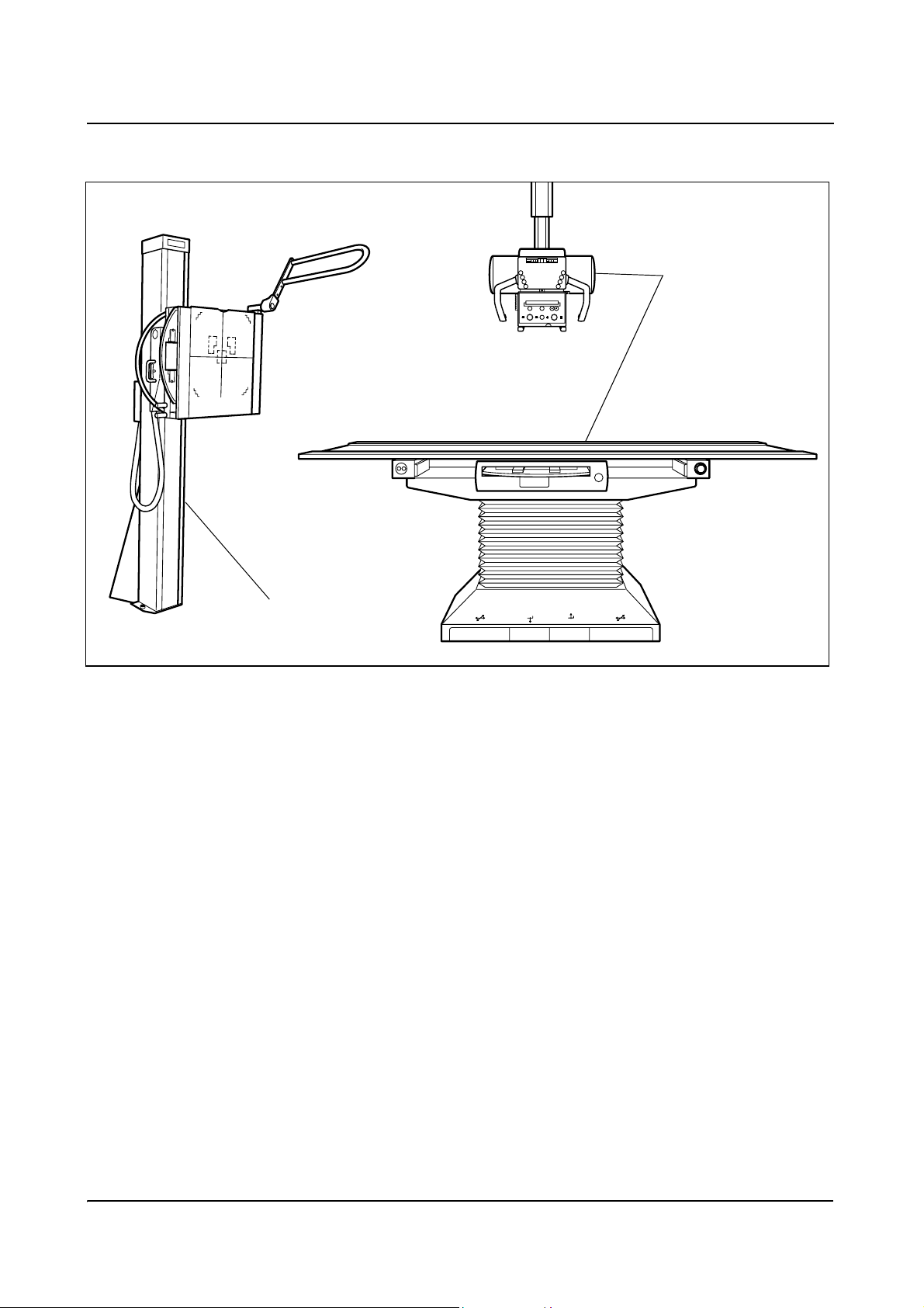
1. "Manual" system version 0
consists of:
MULTIX TOP patient table and 3D ceiling support with
– Motor driven table height adjustment
– "Manual" format collimation
– "Manual" catapult Bucky
– VERTIX TOP, VERTIX PRO or VERTIX S
Operator Manual
6
von 64 AXB1-150.620.01.01.02
Page 13
Product Description
Description
1
5
1
MULTIX TOP P
VERTIX TOP, VERTIX PRO
or VERTIX S
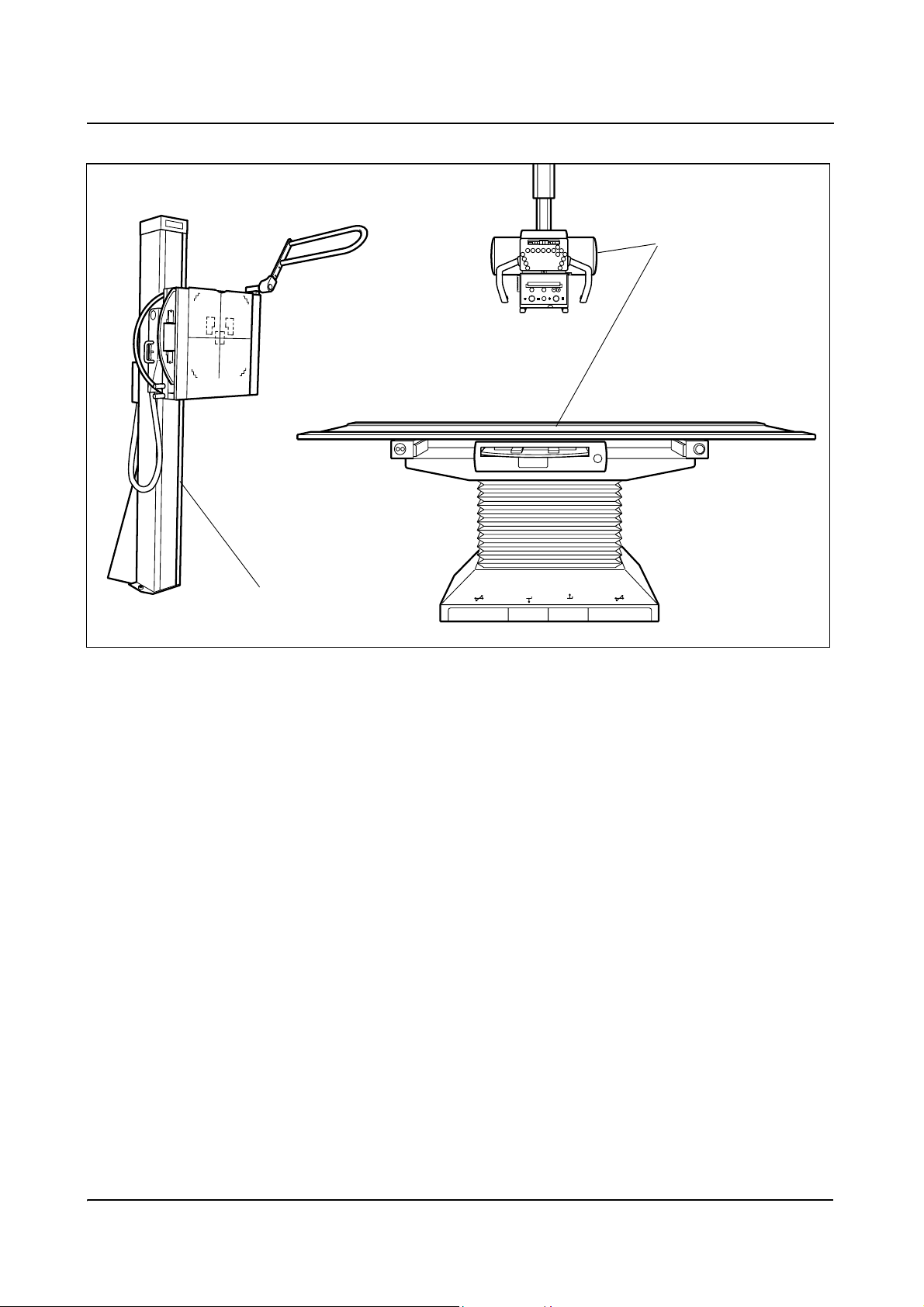
2. "Manual" system version with planigraphy 0
consists of.
MULTIX TOP patient table and 3D ceiling support with:
– Motor driven table height adjustment
– "Manual" format collimation
– "Manual" catapult Bucky
– Tomographic attachment for planigraphy
– Tomographic height light localizer
– VERTIX TOP, VERTIX PRO or VERTIX S
MULTIX TOP
AXB1-150.620.01.01.02 7
von 64
Page 14
Product Description
Description
1
5
1
MULTIX TOP ACSS
M
VERTIX TOP ACSS,
VERTIX PRO ACSS or
VERTIX S ACSS
3. "ACSS" system version 0
consists of:
MULTIX TOP patient table and 3D ceiling support with:
– Motor driven table height adjustment
– ACSS format collimation
– Catapult Bucky with ACSS
– VERTIX TOP ACSS, VERTIX PRO ACSS or VERTIX S ACSS
Operator Manual
8
von 64 AXB1-150.620.01.01.02
Page 15
Product Description
Description
1
5
1
M
MULTIX TOP ACSS P
VERTIX TOP ACSS,
VERTIX PRO ACSS or
VERTIX S ACSS
4. "ACSS" system version with planigraphy 0
consists of:
MULTIX TOP patient table and 3D ceiling support with:
– Motor driven table height adjustment
– ACSS format collimation
– Catapult Bucky with ACSS
– Tomographic attachment for planigraphy
– Tomographic height light localizer
– VERTIX TOP ACSS, VERTIX PRO ACSS or VERTIX S ACSS
MULTIX TOP
AXB1-150.620.01.01.02 9
von 64
Page 16

Product Description
Description
Possibilities of use 0
Patients up to 190 cm tall can be examined from head to toe without repositioning by shifting the tabletop and moving the 3D ceiling support and the
catapult Bucky.
X-ray exposures in the region of the skull, the spinal column (skeleton), the thorax, lungs and abdomen as well as of the extremities can be taken from the lying
and sitting patient on a Bucky table with the MULTIX TOP radiographic system.
In addition, free onto-table exposures or bedside exposures as well as emergency station trolley exposures can be taken.
Exposures of the standing or sitting patient can be taken on the VERTIX PRO/TOP
or VERTIX S Bucky wall stand.
Operator Manual
10
von 64 AXB1-150.620.01.01.02
Page 17

Product Description
Overview
Standard Configuration 0
MULTIX TOP 0
o MULTIX TOP
– with manual collimator
o Generator POLYDOROS IT
o X-ray tube unit with double-focus X-ray tube
o Standard accessories
MULTIX TOP P 0
o MULTIX TOP P
– "Planigraphy " version
– with manual collimator
o Generator POLYDOROS IT
o X-ray tube unit with double-focus X-ray tube
o Standard accessories
MULTIX TOP ACSS 0
o MULTIX TOP ACSS
– with ACSS automatic cassette size sensing collimator
o Generator POLYDOROS IT
o X-ray tube unit with double-focus X-ray tube
o Standard accessories
MULTIX TOP ACSS P 0
o MULTIX TOP ACSS P
– "Planigraphy " version
– with ACSS automatic cassette size sensing collimator
o Generator POLYDOROS IT
o X-ray tube unit with double-focus X-ray tube
o Standard accessories
MULTIX TOP
AXB1-150.620.01.01.02 11
von 64
Page 18

Product Description
Overview
Extensions 0
o VERTIX PRO, VERTIX TOP or VERTIX S Bucky wall stand
o Generator POLYDOROS LX
o Generator POLYDOROS SX
o CAREMAX
o Collision protection
o Optional accessories
Operator Manual
12
von 64 AXB1-150.620.01.01.02
Page 19
Product Description
Overview
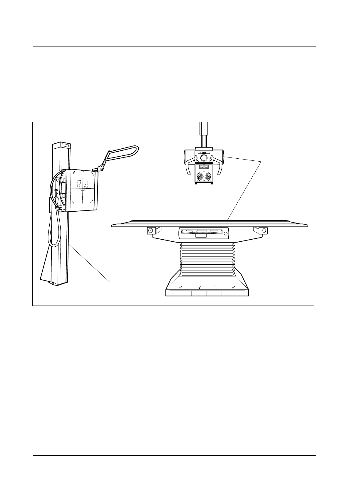
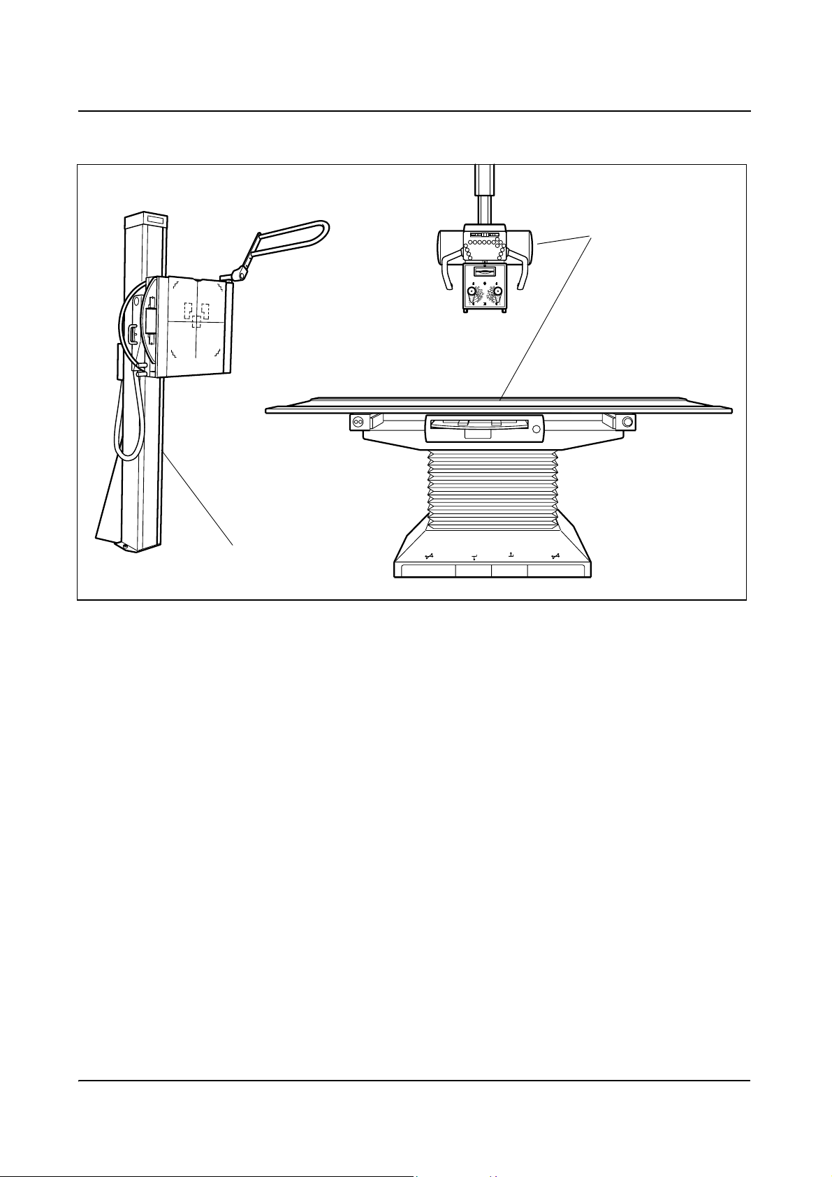
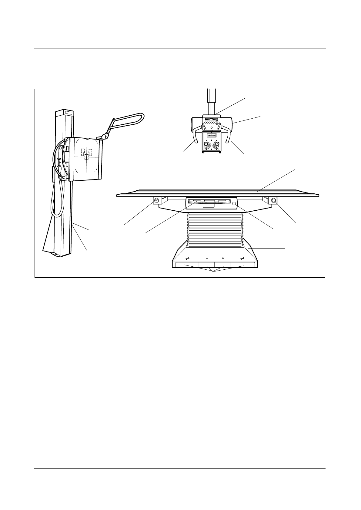
Overall view 0
2
11
10
7
VERTIX TOP, VERTIX PRO
or VERTIX S
Components of the system
1
5
1
5
5
4
3
1
9
12
6
8
(1) Bucky table with positioning tabletop and catapult Bucky
(2) 3D ceiling support with control panel, X-ray tube unit and collimator
(3) X-ray tube unit
(4) Collimator with control panel and displays
(5) Handles for 3D ceiling support/tube unit movement
(6) Table base
(7) Catapult Bucky with cassette tray
(8) Foot switch for tabletop movements and table vertical movement
(9) EMERGENCY STOP button
(10) Signal lamps
(11) VERTIX TOP, VERTIX PRO or VERTIX S Bucky wall unit
(12) Brake handle
MULTIX TOP
AXB1-150.620.01.01.02 13
von 64
Page 20
Product Description
Overview
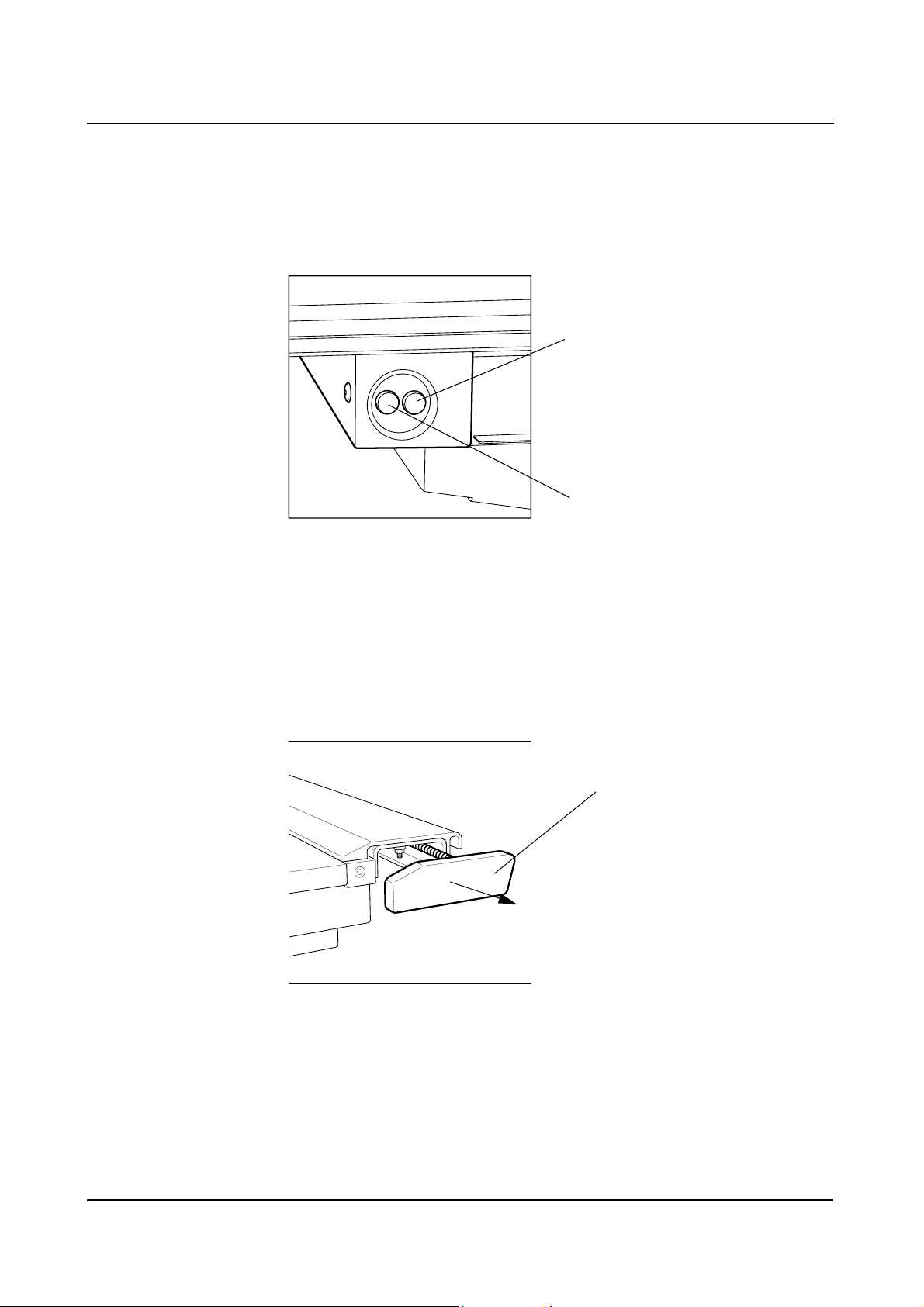
(13) White light: EMERGENCY STOP button activated or security end switch
has responded: 3D ceiling support longitudinal movement or tube rotation or
catapult Bucky movement.
(14) Green light: power supply ON, system operational
Testing the signal lamps
During the initialization phase
the white lamp EMERGENCY
STOP will temporarily light up for
13
testing purposes without the
EMERGENCY STOP button or
security end switch being
activated.
14
Signal lamps (10) at the left side of the patient table
Edge protection on the patient table 0
o The edge protection at the four corners of the patient table securely closes off
the profile rails.
You can pull the edge protection forwards for attaching or removing accessories such as handles, hand switches or other accessories in order to insert the
parts and remove them again.
Edge protection
u Pull the edge protection forwards against the spring tension to insert or
remove accessories.
u Subsequently insert again.
Operator Manual
14
von 64 AXB1-150.620.01.01.02
Page 21

Product Description
Safety Information
General safety 0
Medical electrical equipment needs special precautions regarding Electromagnetic Compliance (EMC). EMC information provided in the accompanying documents must be followed where appropriate.
Portable and mobile RF communications equipment can affect medical electrical
equipment.
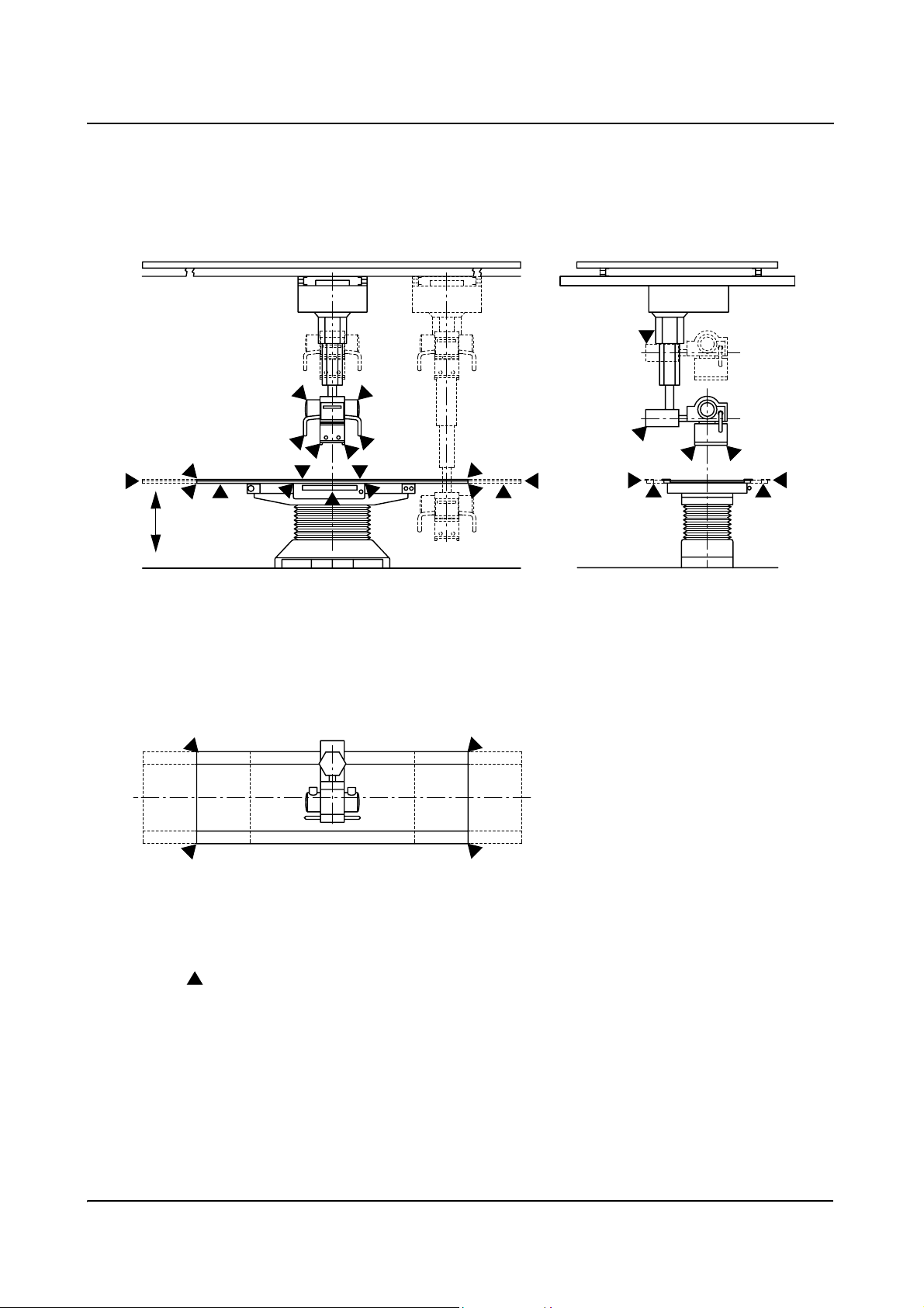
Collision and crushing zones 0
Warning
There is a risk of collision / crushing for patients, operating staff, unit and objects
- caused by unit movements which could be released by inadmissible
actuation of operating elements by patients.
--- possible collicion and crushing zones for patient and operating staff, especially
with respect to extremities, in case of operation errors:
o between patient table and patient tabletop
o between patient table and catapult Bucky
o between patient tabletop and handle of the Bucky
o between patient tabletop and base frame in tabletop movement
o between tube unit and object/floor when moving the tube unit down
o between tabletop and 3D ceiling support when raising or
lowering the tabletop
o between bottom edge of the tabletop and object in table downwards move-
ment
o between persons, MULTIX unit, VERTIX Bucky wall stand, wall or objects and
3D ceiling support during longitudinal or transverse movement or tube unit
rotation about the vertical or horizontal axis.
o when moving the 3D ceiling support outside the specified parking range
o between persons and the 3D ceiling support during motor-operated move-
ment of the patient table
o risk of collision with the handle of the catapult Bucky for the patient when
getting on or off the table.
MULTIX TOP
AXB1-150.620.01.01.02 15
of 64
Page 22

Product Description
Safety Information
o between handles of the 3D ceiling support and the collimator when rotating
the collimator
o at collimator accessory rails
Please take special care when the patient is getting onto or leaving the patient
table that no unintentional activation of the operating elements occurs.
If the patient slips, for instance, it is possible that the table brake may be activated unintentionally, or the active brakes are overridden and thus a system movement occurs.
Warning
The patient and operating personnel may grip only the handles which are inten-
ded for this purpose. If this is not possible, please pay attention to posssible
risks of injury by crushing between moving parts and their guide openings.
The operator is obliged to ensure that system movements are released only if
it is assured that neither the patient nor third parties can be endangered by
these movements.
Operator Manual
16
of 64 AXB1-150.620.01.01.02
Page 23
Product Description
Safety Information
Risk of injury by crushing for operating staff and patients
MULTIX TOP
AXB1-150.620.01.01.02 17
of 64
Page 24

Product Description
Safety Information
Switching on the system on the generator 0
Warning
Make sure before switching on that
all covers and panels are attached to your system.
In this way you avoid foreign parts penetrating into the system.
u You switch your system on and later off again on the generator.
switch on
switch off
– Refer to the Generator register for further information
Please perform the functional and safety check.
– Refer to the Functional and safety check chapter in the
Current information / Safety register
"Manual" system without ACSS automatic format
collimation
u Select the MULTIX TOP or VERTIX PRO/TOP/S or free exposure workstation
at the generator console.
– The tube unit symbol in the control panel lights up
Only if ACSS automatic format collimation is installed 0
u Select the MULTIX TOP or VERTIX PRO/TOP/S or free exposure workstation
at the generator console.
– The "Selected" display
correct ACSS receptor (VERTIX tray or table) has been selected.
– The "X-ray tube unit selected" symbol lights up on the control panel to
confirm that the correct X-ray tube unit has been selected.
1
lights up on the collimator to confirm that the
0
1
Not active when "Free exposure" is selected
Operator Manual
18
of 64 AXB1-150.620.01.01.02
Page 25

Product Description
Safety Information
Warning
Pay attention to the correct selection of the tube unit for the intended
workstation as well as the alignment of the tube unit with the cassette in the
cassette tray, to avoid unintended radiation at the wrong place.
Red EMERGENCY STOP button 0
If an emergency situation arises implying danger for the patient, for the operator
or for the system
u then press the red EMERGENCY STOP button on your system
– This stops all motor driven system movements.
Restarting u Take the patient off from the tabletop.
u Eliminate the dangerous situation.
u If the dangerous situation cannot be eliminated, then please call the Siemens
Uptime Service.
u To unlock the red EMERGENCY STOP button, simply turn it CCW.
➩ You will find further information in the
Current information / Safety register
Red EMERGENCY SHUTDOWN button 0
The EMERGENCY SHUTDOWN button should be installed by the customer on
the wall of the examination room at a well accessible place. It switches off the
power for the entire system and disconnects it from the voltage.
Press this button if the dangerous situation cannot be eliminated by pressing the
EMERGENCY STOP button.
In this case you must not start up the system again.
Please notify the Siemens Uptime Service without delay.
You will find further information in the Current information / Safety register of
this Operator Manual.
MULTIX TOP
AXB1-150.620.01.01.02 19
of 64
Page 26

Product Description
Safety Information
Blockage and fault indicators 0
If fault messages light up at the generator console, then
u Reset the error on the generator pressing the precontact.
u Switch the system off and back on again or
If the indicator does not go out because of this, please notify the Siemens
Uptime Service.
Only for the MULTIX TOP P, TOP ACSS and TOP ACSS P system versions:
If numbers other than 010 (EMERGENCY STOP) light up in the function display
of the control panel with the EMERGENCY STOP button pressed and if the
system does not work as usual then:
u Switch the system off and back on.
If the indicator does not go out because of this, please notify the Siemens
Uptime Service.
– You will find further information in the Generator register
Operator Manual
20
of 64 AXB1-150.620.01.01.02
Page 27

Product Description
Safety Information
Daily Checks 0
Before examinations 0
u Clean the patient tabletop.
u Check all operating elements, system movements, displays and signal lamps.
u In particular, test the function of the system EMERGENCY SHUTDOWN
button and the red EMERGENCY STOP button.
u Attach the required devices for patient restraint and immobilization correctly
to the unit (e.g. hand grips).
u Use the radiation protection accessories required for examining close to the
patient.
u Perform a functional check of the movement of the patient tabletop.
➩ For further information refer to the
Current information/Safety register.
During examinations 0
Warning
The radiation ON indicator may light up briefly only during the duration of the
X-ray exposure.
u Check the patient immobilization, e.g. use of handgrips.
u System movements may be released only if there is no danger for the patient
or third parties and if there are no objects which may obstruct system movements.
MULTIX TOP
AXB1-150.620.01.01.02 21
of 64
Page 28

Product Description
Safety Information
Monthly Checks 0
u Perform a functional check of the system EMERGENCY SHUTDOWN button
and of the red EMERGENCY STOP button.
– You will find additional information on this in the
Current Information/Safety register
u Perform a functional check of the ACSS automatic format collimation.
The three-digit digital display source image distance "SID" may be checked for
conformity with the tape measure in the collimator.
(Working with an ACSS system in the ACSS mode or with a manual collimator,
measure with the tape measure up to the table top and add 5 cm for the
table top - cassette distance.)
We recommend to perform this check on a regular - e.g. monthly - basis.
If the SID values are incorrect, overexposures might occur.
Please notify our Uptime Service if this is the case.
SID checks which are performed on a regular basis will prevent unintentional
overexposures.
Legally required checks 0
u Legally required checks, such as the constancy test in accordance with the
X-Ray Code §16 RöV in the Federal Republic of Germany shall be performed
at the stated time intervals.
Safety-relevant parts subject to wear 0
For safety reasons, steel cables (e.g. in the VERTIX Bucky wall stand) must be
inspected and, if required, changed at a time interval of three years at the most.
Operator Manual
22
of 64 AXB1-150.620.01.01.02
Page 29

Product Description
Safety Information
Maintenance intervals 0
To maintain the safety and function of the system, maintenance must be
performed regularly, at least every 12 months.
(e.g.: periodic relubrication of the lifting spindle of the table lifting column)
u If you have not concluded a maintenance contract, please notify Siemens
Uptime Service.
Behavior in the case of functional disturbances 0
u Please switch the system off and proceed according to the instructions in the
Current information / Safety register.
Cleaning the system 0
u Shut down the system properly before cleaning.
o No moisture may penetrate into the system.
o Plastic surfaces may be cleaned only with a damp cloth with soap solution
since other agents (e.g. with high alcohol contents) can cause the surface to
become dull and liable to crack.
– You will find further information on this in the
Current information / Safety register.
Disinfection of the system 0
u Shut down the system before cleaning.
o Only those disinfection methods which satisfy the applicable regulations and
directives as well as explosion protection may be used.
o No corrosive, dissolving or gaseous disinfectants may be used.
o Spray disinfection is therefore not recommended since disinfectants can
penetrate into the system in this case.
– You will find further information on this in the
Current information / Safety register
MULTIX TOP
AXB1-150.620.01.01.02 23
of 64
Page 30

Product Description
Safety Information
Operator Manual
24
of 64 AXB1-150.620.01.01.02
Page 31

Product Description
Operating Elements
Operating elements for table movements 0
Foot kick switch in the table base 0
1
(1) Actuate the left or right (1) foot kick switch in the tablebase to release the
table brakes. This enables the tabletop to be moved in the longitudinal and
transverse direction.
The function of the switch can be programmed by the Siemens Uptime Service:
o Foot kick switch in "Push-button mode" ("Deadman switch")
The table brakes are released only as long as the switch is actuated.
o Foot kick switch in "Switch mode" ("Sensor switch")
– If the foot kick switch is actuated only one time, the table brakes will be
released. The second time it is actuated, the brakes will be locked again.
If the table brakes are not actuated this second time within a certain time
(time-out time), then the brakes will be locked automatically.
2
3
1
MULTIX TOP
AXB1-150.620.01.01.02 25
of 64
Page 32

Product Description
Operating Elements
The following possibilities can be configured:
– Switching on the full field and LASER line light localizer upon the first
switch actuation
– Automatically switching
1
the full field and LASER line light localizer off
after a preset time, which can be programmed in steps between 20 and 90
seconds. The automatic switch-off can be overridden by pressing the
button (5) on the collimator (see page 35).
– The duration of the time-out period
– Switching on an acoustic alarm
2
(1 to 254 s)
2
the first time the foot switch is actuated.
(2) Operation of the inside foot kick switch / left: for lowering the table
(3) Operation of the inside foot kick switch / right: for raising the table
If desired, the foot kick switches (2) and (3) can be programmed as follows:
o selectable automatic table height intermediate stop
(height between 60 cm and 88 cm continuously adjustable)
Upon reaching the programmed standard table working height, the table is
stopped.
The table will start moving in the desired direction again if the foot kick switches
(2) or (3) are actuated again..
The table brakes cannot be released while the exposure release switch
(precontact) is being actuated..
1
Programmable both for push-button mode and for switch mode
2
Programmable for switch mode only
Operator Manual
26
of 64 AXB1-150.620.01.01.02
Page 33

Product Description
Operating Elements
Operating Elements for 3D Ceiling Support 0
Control panel for
3D ceiling support
Handle (5)
Handle (5)
A
Momentary-contact switches
Example: MULTIX TOP ACSS-P (the different control panels and collimators are described in the
following)
The 3D ceiling support and X-ray tube unit are positioned by the user directly and
manually.
u Use the handles (5) to rotate the X-ray tube unit about the vertical telescopic
axis (+154° to -182°) or about its own horizontal axis (± 120°), thus ensuring
that the X-ray tube is moved in the desired direction.
– Click stops in the vertical axis: every 90°
– Click stops in the horizontal axis: at 0° and ± 90°
u The longitudinal (354 cm), transverse (222 cm) and vertical (150 cm) travels of
the 3D ceiling support with X-ray tube unit are also performed manually using
the handles (5) to ensure that the X-ray tube unit is moved in the desired
direction.
B
u Like "brake release" push button (4) on the control panel, momentary-contact
switches "A" or "B" on the left or right handle release the vertical movement of
the X-ray tube unit on the telescopic column.
– The momentary-contact switches are programmable, i.e. can be set only
for "SID brake" actuation or for "floating" travels as well.
The "floating" travel can in addition be programmed by the SIEMENS Uptime
Service (except for the configuration TOP manual without planigraphy):
– During slow movement over click stops, either to stop or not to stop,
as well as
– "with" or "without" alarm.
MULTIX TOP
AXB1-150.620.01.01.02 27
of 64
Page 34

Product Description
Operating Elements
Warning
Do not exert downward force on the 3D ceiling support if its vertical movement
is blocked! If necessary, it may, however, be moved upward if a continuous
clicking noise can be heard.
Please contact your Siemens Service representative immediately. This is
important, since the main cables may be defective or a spring might be broken.
Such a defect would then mechanically block the downward travel.
Warning
In order to prevent collisions, all longitudinal, transverse or vertical travels and
rotations of the 3D ceiling support must be executed concurrent to manual
guidance of the 3D ceiling support by the operator. Especially important in this
regard is the residual braking distance of the 3D ceiling support following
actuation of the brake switch. This point must be taken into consideration in
order to prevent collisions with persons or objects.
Operator Manual
28
of 64 AXB1-150.620.01.01.02
Page 35

Product Description
Operating Elements
Operating elements and function displays on the control panel 0
1
0,8s
9
1
20
inch
5
10
40˚
1,2s 2,0s
24 25
°
cm
18
18
P
8
28
40˚
26
14
Ready
12
15
27
29
3
1
13
5
16
17
7
ACSS
Manual
19
11
8˚ 8˚ 20˚ 30˚
0,4s 0,8s
6
21
4
5
22
0,6s
23
2
2
Operating elements 0
Operating elements for 3D support and tube unit 0
Moving the 3D support longitudinally only
(1) Actuate the push button for releasing the longitudinal brake.
Moving the 3D support longitudinally and the tube unit up or down
(2) To release the 3-axis brakes press the two identically functioning push buttons
on the control panel or, if programmed accordingly, one of the two identically
functioning momentary-contact switches on the handles.
Moving 3D support transversely only
(3) Press push button for releasing the transverse brake.
MULTIX TOP
AXB1-150.620.01.01.02 29
of 64
Page 36

Product Description
Operating Elements
Operating elements for moving the X-ray tube unit 0
Moving the X-ray tube unit up or down only
(4) Press push button (on the control panel) or, if programmed accordingly, one
of the momentary-contact switches on the handles: release vertical brake.
Rotating the X-ray tube unit about the horizontal axis
(5) Press one of the two push buttons (same function) for releasing the brake to
rotate the X-ray tube unit about the horizontal axis.
Rotating the X-ray tube unit about the vertical axis
(6) Press push button for releasing the brake for vertical tube unit rotation.
Function displays 0
(7) Signal lamp to indicate vertical or horizontal SID on the numeric display (9)
(8) The luminous "P" symbol is not used!
(9) Multifunctional, numeric display (three digit) for:
–SID display (in cm or inches) or
– Angle display in degrees for rotation of the tube unit about the horizontal
axis or
– Tomographic display in cm (only with MULTIX TOP P und TOP ACSS P)
or:
– Error messages:
If the dimension display "cm" or "inches" or "°" (degree) has gone out, the
three-digit numeric display is used for displaying internal error messages.
These error messages are relevant for our Uptime Service.
For example, the error message "010" in the display field means:
"EMERGENCY STOP actuated"
(10) cm = Unit of measurement display for SID
(11) Signal lamp for angle display of the tube unit rotation about the horizontal axis
– The signal lamp lights up when the tube unit is rotated (oblique exposure).
– The signal lamp goes out when the tube unit is in the vertical beam path
(within a tolerance of ± 3°).
– If the 3D ceiling support is located in a preassigned lock-in position to the
Vertix, the signal lamp of the angle display also goes out.
(12) LED lights up "green" if the 3D ceiling support is located in a lock-in position
on the transverse track.
Operator Manual
30
of 64 AXB1-150.620.01.01.02
Page 37

Product Description
Operating Elements
(13) LED lights up "green" if the 3D ceiling support is located in a lock-in position
on the longitudinal track.
– Once the tomographic conditions have been set, the LED for the 3D
ceiling support longitudinal center position switches back off (only with
MULTIX TOP P and TOP ACSS P).
(14) Luminous symbol:"Tube unit on 3D ceiling support selected"
(15) Ready = Unit ready for exposure
(16) ACSS = Auto format (Auto Cassette Size Sensing) mode
(17) Manual = Manual mode, free settings, manual collimation
(18) inch = Unit of measurement display for SID
(19) Signal lamp for display of tomographic plane (only with MULTIX TOP P and
TOP ACSS P)
(20) "°" (degree) = Unit of measurement for angle display
The three-digit digital display source image distance "SID" (9) may be checked for
conformity with the tape measure in the collimator.
We recommend to perform this check on a regular - e.g. monthly - basis.
If the SID values are incorrect, overexposures might occur.
Please notify our Uptime Service if this is the case.
SID checks which are performed on a regular base will prevent unintentional
overexposures.
For ACSS systems with or without planigraphy the following applies:
The system can be programmed for "metric" SID and "metric" cassette formats
by service. If inch-format cassettes are inserted no ACSS mode, and hence, no
automatic format limitation will be activated..
This also applies to the reverse case, i.e. if the system is programmed for the
"inch" format and cassettes with a "metric" format are inserted.
In this case, mixed operation using both "metric" and "inch" cassette formats is
not permissible!
Is the system programmed for mixed operation, mixed operation using both
"metric" and "inch" cassette formats is permissible.
MULTIX TOP
AXB1-150.620.01.01.02 31
of 64
Page 38

Product Description
Operating Elements
Operating elements for planigraphy
(only with TOP P and TOP ACSS P) 0
Selecting the tomographic exposure (tomographic angle and time)
Six functional buttons with green LED:
The LEDs lighten constantly after the corresponding tomographic combination is
selected and if all local mode conditions for planigraphy are fulfilled. During the
adjustment phase the corresponding LED flashes.
(21) 8° / 0,4 s
(22) 8° / 0,8 s
(23) 20° / 0,6 s
(24) 30° / 0,8 s
(25) 40° / 1,2 s
(26) 40° / 2,0 s
Positioning the tomographic plane
Two functional push buttons:
(27) Upward positioning of tomographic plane
(28) Downward positioning of tomographic plane
Disconnecting planigraphy
(29) Symbol: functional push button with green LED
– The LED lightens if the planigraphy is disconnected.
If an operating error occurs during planigraphy, planigraphy is automatically
disconnected.
Operator Manual
32
of 64 AXB1-150.620.01.01.02
Page 39

Product Description
Operating Elements
Operating elements and function displays on
the control panel with analog angle display
(only with MULTIX TOP) 0
7
8
P
120˚
90˚
8
0˚
100˚
110˚
70˚
60˚
50˚
40˚
30˚
6
4
5
2
20˚
1
9
1
10˚
0˚
10˚
5
10
cm
13
12
20˚
120˚
˚
110
100˚
90˚
80˚
70˚
60˚
50˚
40˚
30˚
3
1
5
2
11
Operating elements 0
Operating elements for 3D support and tube unit 0
Moving the 3D support longitudinally only
(1) Actuate the push button for releasing the longitudinal brake.
Moving the 3D support longitudinally and the tube unit up or down
(2) To release the 3-axis brakes press the two identically functioning push buttons
on the control panel or, if programmed accordingly, one of the two identically
functioning momentary-contact switches on the handles.
Moving 3D support transversely only
(3) Press push button for releasing the transverse brake.
MULTIX TOP
AXB1-150.620.01.01.02 33
of 64
Page 40

Product Description
Operating Elements
Operating elements for moving the X-ray tube unit 0
Moving the X-ray tube unit up or down only
(4) Press push button (on the control panel) or, if programmed accordingly, one
of the momentary-contact switches on the handles: release vertical brake.
Rotating the X-ray tube unit about the horizontal axis
(5) Press one of the two push buttons (same function) for releasing the brake to
rotate the X-ray tube unit about the horizontal axis.
Rotating the X-ray tube unit about the vertical axis
(6) Press push button for releasing the brake for vertical tube unit rotation.
Function displays 0
(7) Luminous symbol "tube unit selected"
(8) The luminous symbol "P" is not used!
(9) Three-digit digital display "SID":
–"SID" display (in cm or inches)
(10) Unit measurement display for SID in cm or inch (set by service))
(11) Angle display for turning the tube unit about the horizontal axis
(12) LED lights up "green" if the 3D ceiling support is located in a lock-in position
on the transverse track.
(13) LED lights up "green" if the 3D ceiling support is located in a lock-in position
on the longitudinal track.
The three-digit digital display source image distance "SID" (9) may be checked for
conformity with the tape measure in the collimator.
(Working with an ACSS system in the ACSS mode or with a manual collimator,
measure with the tape measure up to the table top and add 5 cm for the
table top - cassette distance.)
We recommend to perform this check on a regular - e.g. monthly - basis.
If the SID values are incorrect, overexposures might occur.
Please notify our Uptime Service if this is the case.
SID checks which are performed on a regular base will prevent unintentional
overexposures.
Operator Manual
34
of 64 AXB1-150.620.01.01.02
Page 41

Product Description
Operating Elements
Manual collimator 0
Operating elements and displays 0
Front 0
6
4
88
7
1
2
3
5
(1) Locking lever for rotating the collimator about the central-beam axis by ± 50°
with a stop position at 0° (see view of the back of the collimator)
(2) Marking for 0° position of collimator rotation
(0° position if the lever is flush with the edge of the collimator rear panel)
(3) Knob for setting the height format collimation (turn knob to the right to open
the collimator, turn it to the left to close the collimator)
(4) Knob for setting the width format collimation (turn knob to the left to open the
collimator, turn it to the right to close the collimator)
(5) For switching on the radiation field illumination and the LASER line light
localizer.
The devices are switched off automatically by a time switch. The operating
time can be configured (default: 45 seconds); 30 or 60 seconds can be set by
the service engineer. The operating time of the lamp is designed for a patient
load of 150 patients per day. We recommend a total operating time of the light
localizer lamp of 4 minutes within an interval of 10 minutes. If the lamp is
switched on more frequently, the surface of the collimator housing may become hot, thus reducing the operating life of the light localizer lamp.
(6) Prefilter disk with four stop positions:
0; 0.1 mm Cu; 0.2 mm Cu; 0.3 mm Cu
(7) Tape measure tab for SID measurement – pull the tape measure out down-
wards. The measurement is read off the bottom edge of the collimator.
(8) Two accessory rails (left and right) are available for each of the two tray levels.
MULTIX TOP
AXB1-150.620.01.01.02 35
of 64
Page 42

Product Description
Operating Elements
Bottom side 0
A
B
C
D
7
tape measure
A) LASER line light localizer (exit window)
o The LASER line light localizer projects the axis mark required for longitudinal
centering. This mark is aligned with the centering mark on the handle of the
Bucky.
u The LASER line light localizer and full-field light localizer are both switched on
with the pushbutton (5) on the control panel.
They are switched off automatically by an internal time switch.
Warning
LASER radiation
Power ≤ 1mW (EN 60825-1) / wave length 540 - 700 nm
Class 2 LASER product
When the LASER line light localizer is switched on, make sure that nobody
stares directly into the LASER beam to avoid eye injuries or visual disturbances.
Caution – Applications or settings of the knobs or procedures other than those
specified in this document can lead to dangerous radiation exposure.
Operator Manual
36
of 64 AXB1-150.620.01.01.02
Page 43

Product Description
Operating Elements
(B) LASER shutter lever cover
u To cover the exit window of the LASER line light localizer push the LASER
shutter lever to the left.
u To open the exit window of the LASER line light localizer push the LASER
shutter lever to the right.
LASER line light localizer
exit window closed
LASER shutter lever
LASER line light localizer exit window
LASER shutter lever is pushed
to the left, LASER line light localizer exit window is closed
MULTIX TOP
AXB1-150.620.01.01.02 37
of 64
Page 44

Product Description
Operating Elements
(C) Crosshairs
o The crosshairs are used to indicate the longitudinal and transverse axis of the
irradiated field on the cassette or directly on the patient.
u The full-field light localizer for projecting the crosshairs is switched on with the
pushbutton (5) on the control panel. It is automatically switched off by an internal time switch.
o The LASER line light localizer and full-field light localizer cannot be controlled
individually.
LASER line light
(D) Safety lever
o The safety lever is used to lock the compensating filters, templates, etc.
which are inserted into the accessory rails of the collimator, thus preventing
them from dropping out.
➩ See Accessories register (collimator accessories).
u To remove accessories, press the safety lever to the left until you can remove
the compensating filters, templates, etc. from the collimator rails.
➩ See Accessories register (collimator accessories).
Operator Manual
38
of 64 AXB1-150.620.01.01.02
Page 45

Product Description
Operating Elements
Backside 0
(1) Locking lever for
± 50° rotation of the
collimator
Identification labels
Changing the lamp on the collimator 0
Warning
Switch off the system before replacing the lamp.
o The lamp may also be replaced by the user, if necessary.
(Use only original Siemens spare part with part number 8375545)
Mounting screws for
lamp cover
(captive screws are used)
Back of collimator
MULTIX TOP
AXB1-150.620.01.01.02 39
of 64
Page 46

Product Description
Operating Elements
u Switch the system off.
u Turn the collimator until the screws are sufficiently accessible.
u Loosen the three screws on the back using a 2.5 mm Allen key.
u Remove the rear panel and let it hang down.
u Replace the defective plug-in lamp. Do not touch the lamp with bare hands.
Danger of burns!
o Do not touch the new lamp with bare hands (otherwise the lamp may be dam-
aged).
u Insert the new lamp. Make sure that the lamp is properly seated in the plug-
in socket.
u Remount the rear panel and retighten the three screws.
u Switch on the system.
u Perform a constancy test to check for compliance with the permissible limit
values for the light field and radiation field.
If the permissible tolerance values are not complied with, contact Siemens
Customer Service.
u Rear panel removed
Operator Manual
40
of 64 AXB1-150.620.01.01.02
Page 47

Product Description
Operating Elements
u Do not insert the lamp
with bare hands
(use a cloth)
Cloth
Contact pins of lamp
Lamp
u Insert the lamp into the socket
until both contact pins rest
against the base.
Warning
If the halogen lamp of the light localizer is lit for a long time
(repeated switching on), the housing may become hot.
Avoid any contact with the rear of the lamp cover to rule out the risk of burns.
MULTIX TOP
AXB1-150.620.01.01.02 41
of 64
Page 48

Product Description
Operating Elements
Warning
Use only original replacement lamps for the light localizer.
Halogen lamps which are not suitable for switching on and off at short intervals
may burst, thus leading to injuries caused by splintering glass.
Part No.: 8375545
Operator Manual
42
of 64 AXB1-150.620.01.01.02
Page 49

Operation 0
Setting the format collimation 0
o Use the knobs (3) and (4) for setting the height (3) and width (4) collimation.
o Both knobs are provided with a line mark
SID metric Four SID ranges are indicated on the front
– SID of 100cm
– SID of 115cm
– SID of 150cm
– SID of 180cm
Product Description
Operating Elements
3
4
Scales for cassette formats
with selected SID value
Formats For each SID value, scales with the cassette sizes are printed on the device.
u To collimate to a cassette size, set the knobs to a position in which they cor-
respond to the markings and numerical values of the selected SID and the desired cassette size.
MULTIX TOP
AXB1-150.620.01.01.02 43
of 64
Page 50

Product Description
Operating Elements
SID inch Four SID ranges are indicated on the front
Formats For each SID value, scales with the cassette sizes are printed on the device.
or for non-metric designs:
– SID 40 inches
– SID 45 inches
– SID 60 inches
– SID 72 inches
u To collimate to a cassette size, set the knobs to a position in which they cor-
respond to the markings and numerical values of the selected SID and the desired cassette size.
3
4
Scales for cassette formats
with selected SID value
Operator Manual
44
of 64 AXB1-150.620.01.01.02
Page 51

Product Description
Operating Elements
Rotating the collimator about the central beam axis
(up to ± 50°) 0
u Move the locking lever on the back of the collimator in the direction of the ar-
row to rotate the collimator about the central beam axis. This unlocks the 0°
stop position.
u Move the locking lever on the
back of the collimator in the direction of the arrow.
Collimator in 0° stop position
Locking lever on the back of the collimator
Rotate the collimator by up to ±50° to
the left or right end stop
MULTIX TOP
AXB1-150.620.01.01.02 45
of 64
Page 52

Product Description
Operating Elements
Collimator turned to
the right
u With the locking lever actuated, grasp the accessory rails and turn the collima-
tor in the intended direction until you reach the desired angle.
Warning
When turning the collimator, make sure that your hands do not get caught or
crushed between control handles, support arm,
X-ray tube unit, collimator, etc.
Operator Manual
46
of 64 AXB1-150.620.01.01.02
Page 53

Product Description
Operating Elements
Rotating the collimator to the 0° stop position 0
u Grasp the collimator accessory rails and turn the collimator to the centered 0°
stop position.
o The locking lever engages in the 0° position.
Locking lever
o If the collimator is in its locked position,
it is in the 0° position.
Warning
When turning the collimator, make sure that your hands do not get caught or
crushed between control handles, support arm,
X-ray tube unit, collimator, etc.
MULTIX TOP
AXB1-150.620.01.01.02 47
of 64
Page 54

Product Description
Operating Elements
Setting the prefiltration 0
Warning
Before taking any exposures, make sure that the prefilter disk is set to the
correct position! A wrong filter setting may result in an increased radiation
dose for the patient.
o Swiveling prefilter disk: can be accessed on the front of the collimator.
o It can be set to four locking positions.
o For this reason, a total of four combinations are available for prefiltering.
Four positions of the prefilter disk
o 0.0 mm (no) prefiltration
o 0.1 mm Cu prefiltration
o 0.2 mm Cu prefiltration
o 0.3 mm Cu prefiltration
Prefilter disk
Operator Manual
48
of 64 AXB1-150.620.01.01.02
Page 55

Lamp housing of
light localizer
Product Description
Operating Elements
ACSS Collimator 0
Operating elements and displays 0
Front 0
97
1
M
Bottom of
collimator
10
6
8
3542
(1) Locking lever for ± 45° rotation of collimator about the vertical axis
(2) Adjusting knob for fomat height collimation
(turn CCW to close and CW to open collimator)
(3) Adjusting knob for fomat width collimation
(turn CCW to close and CW to open collimator)
(4) X-ray field illumination and LASER line light localizer on/off.
Switch off can also be automatically by a time switch.
On-time can be configured (20, 30, 60 or 90 s).
(5) Tape measure grip for SID measurement
– Take reading at bottom edge of collimator.
8
(6) Plus/minus buttons for manual SID input according to tape measure
(in "Manual" mode only)
(7) MEMORY button for resetting last exposure format used
(effective only if the last exposure format is smaller than the actual cassette
format)
(8) Two accessory rails
MULTIX TOP
AXB1-150.620.01.01.02 49
of 64
Page 56

Product Description
Operating Elements
(9) Function display
(10) Button for selecting collimator-internal Cu prefiltration
Display on the ACSS Collimator 0
Type of collimation
y
m1
y
m1
1
1
Read
5c
Read
5c
Sele tdce
3
33
,
c
Sele tdce
3
Format height Format width SID
o Selected = Bucky workstation on MULTIX table or VERTIX wall stand
selected
c
33
,
C
SS
A
3
m
Type of collimation
Man
3
m
c
33
,
c
33
,
m
lua
m
If "Free exposure" or "Bed" is selected on the generator control console, the
"Selected" display will switch off.
o Ready = Exposure readiness
o ACSS = Auto cassette size sensing mode or:
o Manual = Manual mode, manual collimation
o Format height in cm or in inches
o Format width in cm or in inches
o SID in cm or in inches
Operator Manual
50
of 64 AXB1-150.620.01.01.02
Page 57

Product Description
Operating Elements
Bottom 0
On/off switch (4) for illumination of
M
LASER line light localizer
The LASER line light localizer projects the axis mark for longitudinal centering,
which is aligned with the centering mark on the cassette tray handls.
full-field and LASER line light localizer
LASER line light localizer
Crosshairs for positioning
Locking lever for accessories
Warning
Laser radiation
Power <1mW (EN 60825-1) / wave length 650 nm ± 10 nm /
LASER product class II
When switching on the LASER line light localizer, ensure that nobody looks
directly into the LASER to prevent eye injuries and visual impairment.
Caution - Applications or settings of the knobs or procedures other than those
specified in this document can lead to dangerous radiation exposure.
➩ Refer to the chapter "Centering the X-ray tube unit in relation to the Bucky
wall unit" in register 4.
If necessary, the LASER radiation exit of the LASER line light localizer can be
closed with the sliding cover.
u To switch the LASER line light localizer on, actuate the push button (4) on the
collimator control panel.
u To switch the LASER line light localizer off, actuate the push button (4) again.
– The LASER line light localizer can also be switched off automatically by an
internal time switch.
MULTIX TOP
AXB1-150.620.01.01.02 51
of 64
Page 58

Product Description
Operating Elements
Crosshairs
o The crosshairs project the longitudinal and transverse axis of the radiation field
onto the cassette or directly onto the patient.
u The full field light localizer for projecting the crosshairs is switched on with the
push button (4) on the control panel.
u To switch it off press the push button (4) again.
– The full field light localizer can also be switched off automatically by an
internal time switch.
o The LASER line light localizer and the full field light localizer cannot be
switched independently of one another.
Locking lever
The locking lever is located on the left guide rail at the bottom of the collimator.
The locking lever locks the compensating filters, templates etc. inserted in the
accessory rails of the collimator, thus securing them against falling out.
u To remove the accessories, push the locking lever down until the compensa-
ting filter, template etc. can be removed from the collimator.
➩ Refer to the Accessories register (accessories for the collimator)
Operator Manual
52
of 64 AXB1-150.620.01.01.02
Page 59

Identification
labels
Product Description
Operating Elements
Backside 0
(1) Locking lever
Lamp housing of
light localizer
(1) Locking lever for rotating the collimator about the central beam axis
(up to max. ± 45°)
Warning
The housing can become hot if the halogen lamp of the light localizer burns for
a long perios.
Please avoid contact with the lamp housing to avoid burns.
Warning
Always use original replacement lamps for the light localizer.
Other halogen lamps may not be suitable for switching on and off at short
intervals (they may break and cause injuries due to broken glass).
MULTIX TOP
AXB1-150.620.01.01.02 53
of 64
Page 60

Product Description
Operating Elements
Changing the collimator lamp 0
If required, the lamp of the collimator can also be changed by the user.
Lamp housing
Two Allen screws
Left side of the collimator
u Switch the system off at the generator control console.
u Remove both Allen screws on the lamp housing.
u Remove the lamp housing.
u Remove the two Allen contact screws on the lamp.
u Replace the defective lamp.
– Do not touch it with bare fingers, since the lamp can be very hot!
u Open the protective cover of the new lamp at the head end.
u Insert the new lamp with protective cover into the lamp socket until both pins
rest against the base.
– Do not touch the new lamp with bare fingers!
u Align the lamp horizontally.
u Tighten both Allen contact screws on the lamp.
u Remove the protective cover.
u Refit the lamp housing and tighten both screws on the lamp housing again.
Operator Manual
54
of 64 AXB1-150.620.01.01.02
Page 61

Product Description
Operating Elements
Operation 0
Rotating the collimator about the central beam axis
(max. up to ±45°) 0
ACSS
Manual
1
8¡ 8¡ 20¡ 30¡ 40¡
0,4s 0,8s
0,6s
inch
Ready
P
cm
5
1
40¡
1,2s 2,0s0,8s
Locking lever (1)
Max. ± 45° rotation of the collimator
M
Collimator in th 0° stop position
to the right or left stop
u Move the locking lever (1) on the collimator towards the front plate to the
operator.
– the 0° stop is released
1
1
5
5
1
1
M
M
Collimator rotated clockwise
u Grip the collimator and turn it by the desired angle in the desired direction.
MULTIX TOP
AXB1-150.620.01.01.02 55
of 64
Page 62

Product Description
Operating Elements
Rotating the collimator into the 0° stop position 0
u Grip the collimator and turn it to the centered 0° stop position.
Warning
When gripping the collimator to rotate it, make sure there is no danger of
crushing your hands between the handles and the collimator.
Indication of the collimator 0° stop position 0
The 0° stop position of the collimator is indicated with the locking lever (1) on the
right side of the collimator.
Locking lever (1)
0° stop position:
Locking lever points to the
rectangular mark
Operator Manual
56
of 64 AXB1-150.620.01.01.02
Page 63

Product Description
Operating Elements
Setting the prefiltration 0
Internal motor-driven Cu prefilter
There are four possibilities of selecting internal Cu prefilters:
o 0,0 mm (no) prefiltration
o 0,1 mm Cu prefiltration
o 0,2 mm Cu prefiltration
o 0,3 mm Cu prefiltration
Selecting Cu prefilters You can change the setting of Cu prefilters by selecting the button (2) on the
collimator:
o The display (1) always indicates the existing Cu prefilter value.
u Press the button (2) on the collimator once.
o The display (1) indicates the updated Cu prefilter value.
u By repeatedly pressing the button (2) you switch in each case to the next
Cu prefilter value.
– You switch through the Cu prefilters one after the other.
– The selected Cu prefilter is indicated in each case on the display (1) of the
collimator.
Warning
A wrong filter setting may result in an increased radiation dose for the patient.
u Please make sure on the display that the required Cu prefilter is selected.
MULTIX TOP
AXB1-150.620.01.01.02 57
of 64
Page 64

Product Description
Operating Elements
Display field on the ACSS collimator
Typ of collimation
selected internal
Cu prefilter: 0,1 mm Cu
Display of the selected
Cu prefilter
5c
y
m1
Sel e tdce
m
1
m
0.
o On the display (1) of the collimator apart from other data the
current selection of the internal Cu prefilter in mm is indicated:
The following further data are also indicated on the display:
o Selected = workstation is selected at the radiographic table or at the
radiographic stand
o ACSS = operation with automatic cassette sensing
Automatic
Cassette
Size
Sensing
Cu
Man
3
3.
c
3
m
Format height Format width SID
lua
3c
3.3
m
Read
1
o Manual = manual operation, manual collimation
o Ready = ready for exposure
The Ready display is out, only if, for exposures with horizontal beam path on a
Vertix in ACSS systems with or without planigraphy, the 3D ceiling support is
not positioned in a programmed stop in relation to the Vertix, but otherwise
fulfills ACSS requirements. This indicates that manual Bucky mode on the Vertix
with horizontal beam path is not possible..
o Format height in cm or in inch
o Format width in cm or in inch
o SID in cm or in inch
Operator Manual
58
of 64 AXB1-150.620.01.01.02
Page 65

Product Description
Operating Elements
Operating elements on the manual or ACSS cassette tray 0
11
12
10
3
6
5
9
8
4
Mid centering mark
1
8
7
2
(1) Cassette tray
(2) Handle with slide-in unlocking button
(3) Cassette stop (format limit/format stop) adjustable
(4) Rear clamping jaw with mid centering mark
(5) Front clamping jaws
(6) Format scales (cm and inch)
(7) Axial mark for mid centering with LASER line light localizer of the collimator
(8) Lead letter holder
(9) Two spring stop levers (release catch for removing the cassette tray)
(10) Unlocking lever for grid changing (beneath the grid cover)
(11) Grid cover
(12) Brake handle
MULTIX TOP
AXB1-150.620.01.01.02 59
of 64
Page 66

Product Description
Operating Elements
Brake handle 0
Position of the brake handle 0
The brake handle is located on the right side of the catapult Bucky.
Function of the brake handle 0
The brake handle is used to guide the catapult Bucky in the table longitudinal
direction during manual movements and to stop it in each position.
Brake handle (12)
Operating the brake handle 0
u To move the catapult Bucky in the longitudinal direction, release the brake by
pulling the handle (12).
(Exception: During the active planigraphic mode the brake cannot be released
anymore.)
The catapult Bucky can be moved longitudinally and positioned only with the
handle (12).
u To stop the movement of the catapult Bucky in the longitudinal direction, let
go of the handle (12) when the Bucky has been positioned.
When inserting the cassettes into the cassette tray, ensure that the cassettes
are centered correctly in the tray.
Operator Manual
60
of 64 AXB1-150.620.01.01.02
Page 67

Product Description
Operating Elements
Operating and display elements of the
follow-up control (only with ACSS and ACSS P) 0
Overall view 0
3D ceiling support
with X-ray tube unit
and collimator
Control panel
Push button for
MULTIX constant SID
EMERGENCY STOP switch
MULTIX TOP
AXB1-150.620.01.01.02 61
of 64
Page 68

Product Description
Operating Elements
Control panel and displays for ceiling support settings 0
Operating elements for motor-driven height adjustment (vertical) 0
ACSS
Manual
8˚ 8˚ 20˚ 30˚
0,4s 0,8s
1
2
1. Push button for motor-driven tube unit upwards movement
0,6s
1
1
5
40˚
1,2s 2,0s0,8s
inch
˚
cm
P
Ready
40˚
2. Push button for motor-driven tube unit downwards movement
Operator Manual
62
of 64 AXB1-150.620.01.01.02
Page 69

Product Description
Operating Elements
Operating elements on the patient table 0
Operating elements for MULTIX constant SID 0
3
3. Push button for MULTIX constant SID
MULTIX TOP
AXB1-150.620.01.01.02 63
of 64
Page 70

Product Description
Operating Elements
Operator Manual
64
of 64 AXB1-150.620.01.01.02
Page 71

System operation and radiography
Table of Contents
Operator Manual
System operation and radiography
Chapter: Operation
Inserting and removing a cassette ..................................................................................... 5
Inserting a cassette ......................................................................................................... 5
Removing the cassette .................................................................................................. 10
Removing the cassette tray ............................................................................................. 11
Inserting cassette tray .................................................................................................... 12
Using the lead letters ..................................................................................................... 13
Grid changing .................................................................................................................... 14
Removing the grid ......................................................................................................... 14
Inserting a grid ............................................................................................................. 15
Centering the tube unit in relation to the Bucky table ...................................................... 18
Vertical projection ......................................................................................................... 18
Centering in the longitudinal direction ....................................................................... 18
Centering in the transverse direction ........................................................................ 18
Setting the SID .................................................................................................... 18
Centering the tube unit in relation to the Bucky wall unit ................................................. 19
Horizontal projection with four fixed SIDs ........................................................................... 19
Centering in the transverse direction ........................................................................ 19
Height centering .................................................................................................. 19
Setting the SID .................................................................................................... 19
Moving the tabletop ......................................................................................................... 20
in the longitudinal and transverse directions: ....................................................................... 20
Table height: ................................................................................................................ 20
Moving the catapult Bucky ............................................................................................... 20
in the longitudinal direction: ............................................................................................. 20
in the transverse direction: .............................................................................................. 20
Moving the tube unit (with 3D ceiling support) ................................................................ 20
in the vertical direction: .................................................................................................. 20
in the longitudinal direction: ............................................................................................. 20
in the transverse direction: .............................................................................................. 20
MULTIX TOP
AXB1-150.620.01.01.02 1
von 90
Page 72

System operation and radiography
Table of Contents
Follow-up control (only for ACSS and ACSS P) ................................................................. 21
Operating modes of the follow-up control .......................................................................... 21
Manually controlled motor-driven height adjustment of the tube unit ....................................... 22
Function ............................................................................................................. 22
Operation ........................................................................................................... 22
Automatic control for constant SID on the MULTIX table (vertical projection) ............................. 25
Function ............................................................................................................. 25
Operation ........................................................................................................... 25
Rotating the tube unit ....................................................................................................... 28
about the vertical axis: ................................................................................................... 28
about the horizontal axis: ................................................................................................ 28
Rotating the collimator ..................................................................................................... 28
about the central beam axis: ............................................................................................ 28
Centering onto the catapult Bucky in the MULTIX patient table ...................................... 28
in the longitudinal direction: ............................................................................................. 28
in the transverse direction: .............................................................................................. 28
Centering onto the catapult Bucky in the VERTIX Bucky wall unit ................................... 29
in the transverse direction: .............................................................................................. 29
in the vertical direction (horizontal projection): ..................................................................... 29
Positioning the patient on the patient table ...................................................................... 30
Positioning the patient ...................................................................................................... 31
Chapter: Radiography
Catapult Bucky with ACSS automatic format collimation ................................................. 33
Components of the ACSS automatic format collimation ........................................................ 33
Conditions for the ACSS automatic format collimation .......................................................... 33
Function of ACSS automatic format collimation ............................................................... 34
Purpose of ACSS automatic format collimation ................................................................... 34
Functional Description of the ACSS System ....................................................................... 34
Preconditions for the ACSS Mode .................................................................................... 35
ACSS Mode ................................................................................................................. 36
For Table or BWS Radiography in the Vertical Beam Path ............................................. 36
For Bucky Wall Stand Radiography in the Horizontal Beam Path ..................................... 37
Operation in the "ACSS" Mode ......................................................................................... 37
Exposures on the MULTIX Patient Table ................................................................... 37
Exposures on the VERTIX PRO or VERTIX TOP Bucky Wall Stand .................................. 38
Operator Manual
2
von 90 AXB1-150.620.01.01.02
Page 73

System operation and radiography
Table of Contents
Preconditions for Manual Operation without the automatic format collimation ........................... 39
Manual Mode ............................................................................................................... 39
Operation in the "Manual" Mode ....................................................................................... 40
Exposures on the MULTIX Patient Table ................................................................... 40
Exposures on the VERTIX PRO or VERTIX TOP Bucky Wall Stand .................................. 41
Extended Operating messages ........................................................................................ 42
Exposure Possibilities with ACSS Collimator ................................................................... 43
Centered Bucky Exposure with Vertical Beam Path .............................................................. 43
"ACSS Mode" ...................................................................................................... 43
Exposures with a Vertical Beam Path: "Free On-table" or "Bucky" Exposures .............................. 45
"Manual Mode" .................................................................................................... 45
Oblique Projections: "Free On-table" or "Bucky Exposures" ..................................................... 48
"Manual Mode" .................................................................................................... 48
Free Lateral Exposures .................................................................................................. 51
"Manual Mode" .................................................................................................... 51
Bucky Exposure Centered on Bucky Wall Stand: Horizontal Beam Path .................................... 53
"ACSS Mode" ...................................................................................................... 53
Exposures with Horizontal Beam Path: "Free BWS or Bucky Exposure“ ................................... 55
"Manual Mode" .................................................................................................... 55
Oblique Projections: "Free BWS" or "Bucky Exposure" (with VERTIX TOP and VERTIX S only) ........ 57
"Manual Mode" .................................................................................................... 57
Centered Bucky Exposure with Vertical Beam Path on VERTIX TOP Bucky Wall Stand ................ 59
"ACSS-Mode" ...................................................................................................... 59
Exposures with a Vertical Beam Path: "Free BWS" or "Bucky Exposure" .................................... 61
"Manual Mode" .................................................................................................... 61
Radiographic possibilities with Manual Collimator ........................................................... 64
Centered Bucky exposure with vertical projection ................................................................ 64
Free onto-table or "Bucky" exposure with vertical projection ................................................... 67
Oblique oblique exposure or oblique Bucky exposure ........................................................... 69
Free lateral exposure ..................................................................................................... 71
Centered Bucky exposure onto Bucky wall unit,horizontal projection ....................................... 73
Exposure with horizontal projection as "Free BWS exposure" ................................................. 75
Centered Bucky exposure with vertical projection onto the VERTIX TOP Bucky wall unit ............. 77
"Free exposure" with vertical projection onto the VERTIX TOP Bucky wall unit ........................... 80
Planigraphy exposure ....................................................................................................... 82
Taking planigraphic exposures ................................................................................. 83
IONTOMAT automatic exposure control .......................................................................... 88
Exposure release .............................................................................................................. 89
Memory Function (only with MULTIX ACSS collimator) ................................................... 90
MULTIX TOP
AXB1-150.620.01.01.02 3
von 90
Page 74

System operation and radiography
Table of Contents
Operator Manual
4
von 90 AXB1-150.620.01.01.02
Page 75

System Operation / Radiography
Operation
Inserting and removing a cassette 0
Inserting a cassette 0
All cassettes with formats of 13 cm x 18 cm to 35 cm x 43 cm or 5" x 7" to 14" x
17" can be inserted "vertically" or "horizontally" for exposures.
The cassette tray does not provide for format segmentations.
Cassette inserted "vertically"
Longitudinal axis
Cassette inserted "horizontally"
Transverse axis
Patient table
Warning
Incorrect cassette insertion may result in the fingers being crushed between the
cassette and the clamping jaws of the cassette tray.
Be careful not to drop the cassette when inserting and removing it, since this
may cause foot injuries.
Caution
The withdrawn cassette tray may be loaded only with the weight of a cassette.
All other mechanical loads must be excluded.
Do not insert or remove the cassette tray from the catapult Bucky by force.
Improper handling can lead to damage and failure of the Bucky.
MULTIX TOP
AXB1-150.620.01.01.02 5
von 90
Page 76

System Operation / Radiography
Operation
2
u Release the cassette tray (1) with the handle (2) and pull it out until it engages.
– Mechanical stops prevent the cassette tray from falling out of the catapult
Bucky.
For ACSS systems with or without planigraphy the following applies:
The system can be programmed for "metric" SID and "metric" cassette formats
by service. If inch-format cassettes are inserted no ACSS mode, and hence, no
automatic format limitation will be activated
This also applies to the reverse case, i.e. if the system is programmed for the
"inch" format and cassettes with a "metric" format are inserted.
1
In this case, mixed operation using both "metric" and "inch" cassette formats is
not permissible!
Is the system programmed for mixed operation, mixed operation using both
"metric" and "inch" cassette formats is permissible.
Operator Manual
6
von 90 AXB1-150.620.01.01.02
Page 77

System Operation / Radiography
Operation
Cassette stop (3)
,5
,5
5
6
6
7
8
8
13
15
18
20
s
,5
0
1
2
4
9
1
1
24
25
5
1
in
1
1
30
cm
35
40
Guide rail (3.1)
Scales (6)
u Compress the cassette stop on the right (3) a little until the stop can be
moved on the guide rail (3.1).
u Move the cassette stop (3) to the wanted cassette format and let it snap into
position.
– You can read off the format directly above the stop.
– The cassette stop serves for more convenient centering and with respect
to the vertical Bucky wall stand also for fixing the cassette you insert
o The two scales (6) on the cassette tray indicate the possible cassette format
limits of the cassette height for cm and inch formats.
Rear clamping jaw (4) with
mid centering mark
u Grip the cassette at the front.
u Push the cassette against the rear clamping jaw (4) and while doing so make
the mid centering mark of the cassette coincide with the mid centering mark
of the rear clamping jaw. (Centering aid)
MULTIX TOP
AXB1-150.620.01.01.02 7
von 90
Page 78

System Operation / Radiography
Operation
u Push the cassette against the right format stop (3) while doing this.
3
5
u Keeping the cassette held at the front, let it lower and spring back when
pushed in further until the two front clamping jaws (5) grip the cassette.
When inserting the cassette special attention needs to be paid to the correct
longitudinal centering of the cassette in the cassette tray.
Cassettes which are inserted out of the center may cause recognition errors.
(only with ACSS automatic format collimation)
Operator Manual
8
von 90 AXB1-150.620.01.01.02
Page 79

System Operation / Radiography
Operation
(1) Handle
u Grip the cassette tray handle (2) so that the tray lock is unlocked.
u Using the handle (2) push the cassette tray with the inserted cassette in up to
the stop.
– The cassette is correctly centered in the cassette tray if it was inserted as
described.
Warning
Observe the following adjustment
to avoid radiation which does not contribute to the image:
Make sure that you center the cassette exactly in the cassette tray with the aid
of the cassette stop and the centering mark of the clamping part in the longitudinal direction.
In this way you avoid overframing and thus reduce the radiation exposure of the
patient.
The centering in the transverse direction is automatically performed by the selfcentering clamping jaw.
MULTIX TOP
AXB1-150.620.01.01.02 9
von 90
Page 80

System Operation / Radiography
Operation
Removing the cassette 0
(1)
u Grip the cassette tray handle (1) and withdraw the cassette tray (2) until it
latches into position.
– Mechanical stops prevent the cassette tray with the cassette falling out
from the catapult Bucky.
(2)
Front clamping jaws (1)
u Grip the cassette at the front and push it away from you until the front
clamping jaws (1) release the cassette.
u Then lift the cassette and remove it from the cassette tray.
Operator Manual
10
von 90 AXB1-150.620.01.01.02
Page 81

System Operation / Radiography
Operation
Removing the cassette tray 0
With respect to normal operation the cassette tray does not need to be removed.
However, it may be necessary in order to be able to pick up objects (e.g. lead
letters) which fell down from the cassette tray after the cassette tray is removed.
(2) two spring stop levers
(1) Cassette tray
u Pull on the handle of the cassette tray (1) until it latches into position.
right spring stop lever (1)
left spring stop lever (1)
u Hold the cassette tray horizontal with both hands.
u Press the left and right spring stop lever (1) inwards with your thumbs in order
to release the withdrawal lock and pull the cassette tray out completely horizontally.
MULTIX TOP
AXB1-150.620.01.01.02 11
von 90
Page 82

System Operation / Radiography
Operation
Inserting cassette tray 0
u Hold the cassette tray horizontally with both hands and bring it up to the cata-
pult Bucky guideway.
1
u Push the cassette tray horizontally up to the first stop.
u Release the further movement of the cassette tray by pressing the catch in
the handle (1).
Operator Manual
12
von 90 AXB1-150.620.01.01.02
Page 83

System Operation / Radiography
Operation
u Push the cassette tray in up to the end stop.
Using the lead letters 0
2
R
R
L
1
L
R
L
3
The lead letters "R" and "L" are located in the holders (1). The letters have a
magnetic holder and are set on the cassette as required for right or left marking
of the next exposure object. (2)
You should re-insert the lead letters in the holders for safe keeping. (3)
It is up to the operator to exercise due care to make sure that the R/L marks are
inserted correctly, in order to exclude a wrong diagnosis.
MULTIX TOP
AXB1-150.620.01.01.02 13
von 90
Page 84

System Operation / Radiography
Operation
Grid changing 0
The user is basically responsible for the use and the corresponding selection of
the scattered radiation grid used in each case.
Removing the grid 0
u Push the tabletop away from you.
Grid cover (1)
u Lift the spring-loaded grid cover (1) and hold it.
Unlocking lever (1)
u Push the unlocking lever (1) down.
– The grid (2) moves towards the operator.
Operator Manual
14
von 90 AXB1-150.620.01.01.02
Page 85

System Operation / Radiography
Operation
Grid (2)
Tab (1)
Tab (1)
An angled tab (1) is provided in the center of the grid.
The grid type is indicated on this tab.
u Use the tab (1) to pull the grid out horizontally and take it out with both hands.
u Carefully close the grid cover.
Inserting a grid 0
u Hold the grid horizontally.
The tube unit symbol on the grid must point to the tube unit.
Grid rail (2)
tube unit symbol
Front guide tab (1)
u Hold the grid with both hands.
u Lift the spring-loaded grid cover with one forefinger and hold it.
Rear guide tab
u Place the front guide tab (1) of the grid into the left guide rail of the catapult
Bucky.
MULTIX TOP
AXB1-150.620.01.01.02 15
von 90
Page 86

System Operation / Radiography
Operation
u Slightly press down the unlocking lever (10) on the right side with the grid rail
on the right.
u Push the grid in horizontally without bending.
Unlocking lever (10)
u In doing so, ensure that both guide tabs on the left and the grid rail on the right
are accurately inserted into the respective guiding groove of the catapult
Bucky profile.
u Hold the grid by the tab with one hand while lifting the spring-loaded grid co-
ver with the other hand.
u Slowly insert the grid all the way to the stop, then push it to the right until the
unlocking lever (10) on the right-hand side moves up again and engages.
Grid cover (11)
u Carefully close the grid cover (11).
When inserting the scattered radiation grids, it is essential that the grid
corresponds to the intended source-image-distance (SID) to which the grid is
focussed.
Operator Manual
16
von 90 AXB1-150.620.01.01.02
Page 87

System Operation / Radiography
Operation
Because of the focussing of the grids, the tube unit must be centered onto the
Bucky.
MULTIX TOP
AXB1-150.620.01.01.02 17
von 90
Page 88

System Operation / Radiography
Operation
Centering the tube unit in relation to the Bucky table 0
Vertical projection 0
Centering in the longitudinal direction 0
R
L
The central ray should strike the center of the cassette.
u To do this, align the axis mark (7) on the cassette tray handle with the LASER
line light mark of the light localizer.
or:
u Move the catapult Bucky until it reaches the center stop.
u Move the 3D ceiling support until it reaches the center stop.
– The central ray is then centered to the respective cassette center.
Axis mark (7)
LASER line light mark
Centering in the transverse direction 0
u Move the 3D ceiling support transversely until it reaches the center stop.
With the cassette tray pushed in the cassette, if inserted as described, is already
centered in the transverse direction.
It therefore only needs to be centered in the longitudinal direction.
Setting the SID 0
u Always set the SID so that it corresponds to the focussing of the grid used.
Operator Manual
18
von 90 AXB1-150.620.01.01.02
Page 89

System Operation / Radiography
Operation
Centering the tube unit in relation to the Bucky wall unit 0
Horizontal projection with four fixed SIDs 0
Centering in the transverse direction 0
With the cassette tray pushed in, the cassette - if inserted as described - is
already centered in the transverse direction if the telescope carriage of the 3D
ceiling support in the transverse carriage is in the mid-center position in relation
to the Bucky wall unit.
It therefore only needs to be centered in height.
Height centering 0
Center the tube unit in height in relation to the cassette center.
u To do this, align the axis mark (7) on the cassette tray handle with the line light
mark of the LASER line light localizer.
Setting the SID 0
The 3D ceiling support can be set by service personnel to a maximum of four fixed SID stop positions.
Always set the SID so that it corresponds to the focussing of the grid used.
We recommend that you center accurately.
Uncentered grid exposures can result in grid shadows on the radiographs.
Accurate centering impoves image quality.
MULTIX TOP
AXB1-150.620.01.01.02 19
von 90
Page 90

System Operation / Radiography
Operation
Moving the tabletop 0
in the longitudinal and transverse directions: 0
o manually after releasing the brakes
Table height: 0
o Raising the tabletop: by motor
o Lowering the tabletop: by motor
Moving the catapult Bucky 0
in the longitudinal direction: 0
o manually
in the transverse direction: 0
o no movement
Moving the tube unit (with 3D ceiling support)
in the vertical direction: 0
o manually (e.g. setting the vertical SID) after releasing the brakes
in the longitudinal direction: 0
o manually (e.g. setting the horizontal SID) after releasing the brakes
0
in the transverse direction: 0
o manually (e.g. centering) after releasing the brakes
Operator Manual
20
von 90 AXB1-150.620.01.01.02
Page 91

System Operation / Radiography
Operation
Follow-up control
(only for ACSS and ACSS P) 0
Operating modes of the follow-up control 0
There are four different operating modes of the follow-up control:
o Manually controlled motor-driven height adjustment of the tube unit
o Automatic height follow-up of the tube unit to the VERTIX TOP
(horizontal projection)
➩ Refer to the VERTIX TOP Operator Manual.
o Automatic control for constant SID on the MULTIX table (vertical projection)
o Automatic control for constant SID on the VERTIX TOP (vertical projection)
➩ Refer to the VERTIX TOP Operator Manual.
o On selection of the tomographic mode (planigraphy), the 3D overhead support
is moved automatically (if programmed that way by the Technical Service) into
the “Planigraphy” starting position that can be programmed by the Technical
Service. The associated table height must be actuated by operating the foot
kick switch. The automatic “Table height stop” then takes place at the table
height determined for planigraphy and thus corresponds to the intended SID
for planigraphy.
MULTIX TOP
AXB1-150.620.01.01.02 21
von 90
Page 92

System Operation / Radiography
Operation
Manually controlled motor-driven height adjustment of
the tube unit
Function 0
o Manual operation of the push button in the control panel of the 3D ceiling
support for tube unit upwards or downwards movement releases the brakes
of the vertical movement of the tube unit and moves the tube unit on the 3D
ceiling support by motor drive in the required direction.
o The set radiation direction has no influence on the control of the motor-driven
height adjustment of the tube unit. The radiation direction can thus be freely
selected.
o Motor-driven total vertical movement 1480 mm (± 10 mm)
(unless limited by the Technical Service on customer preference)
Motor-driven height adjustment of
the 3D ceiling support with tube
unit
0
Operation 0
o The operating elements are located on the control panel for the 3D ceiling
support
o Manual choice of motor-driven height adjustment with normal speed:
u Push button operation for motor-driven tube unit upwards movement
u Push button operation for motor-driven tube unit downwards movement
– The motor-driven movement of the tube unit occurs only for the duration in
which a push button is pressed.
Operator Manual
22
von 90 AXB1-150.620.01.01.02
Page 93

System Operation / Radiography
Operation
– It is possible to release automatic switch-on of the light localizer with
LASER line light localizer on the collimator when operating the push button
for motor-driven tube unit upwards or downwards movement, if so
required. In this case the Technical Service can activate this programmable
function.
– Automatic end shutdown protects the tube unit upwards or downwards
movement if the tube unit on the 3D ceiling support has reached the upper
or the lower end position.
– During the installation of the system it is possible to determine a selectable
stop position for a SID value of 102 cm or 115 cm.
If the tube unit reaches the predetermined SID value when moving, then
the motor-driven movement is ended.
– The tube unit moves on in the required direction only after pressing a push
button for tube unit upwards or downwards movement once again.
o Prerequisites for the motor-driven height adjustment of the tube unit:
– Push button for motor-driven tube unit upwards or downwards
movement pressed
– No overhead support end position reached
– No collision protection has responded
– No EMERGENCY STOP switch operated
Warning
Please pay attention to collision-free movements of the 3D ceiling support
with tube unit and collimator, to protect patients and objects
against damage.
MULTIX TOP
AXB1-150.620.01.01.02 23
von 90
Page 94

System Operation / Radiography
Operation
o The automatic collision protection is a safety device for protecting the
patient.
Function:
– If during motor-driven movement of the 3D ceiling support with tube unit
and collimator a collision occurs in the downwards direction, a force of not
more than 200 N becomes effective to protect the patient and objects.
– On response of the automatic collision protection, a brief acoustic signal
sounds as alarm to the operator.
– The motor-driven movement is then immediately ended.
– After pressing the push button for the motor-driven upwards movement or
manually, after releasing the vertical brakes, the tube unit on the 3D ceiling
support can be moved again out from the collision zone, also by motordriven lowering of the patient tabletop.
– For the protection of the patient and objects, the automatic collision protec-
tion is also effective in the upwards direction, if for instance the 3D ceiling
support with tube unit and collimator is moved under the patient table of
the MULTIX table or other objects such as a sickbed etc. A force of not
more than 200 N becomes effective in the collision.
– On response of the automatic collision protection, a brief acoustic signal
sounds as alarm to the operator.
– After pressing the push button for the motor-driven downwards movement
or manually, after releasing the vertical brakes, the tube unit on the 3D
ceiling support can be moved again out from the collision zone.
o To assure patient rescue in the case of a power failure with braked 3D ceiling
support, the tube unit on the 3D ceiling support can be pushed manually with
a force of 200 N out from its braked position.
o The motor-driven movement of the tube unit is not possible if:
– The EMERGENCY STOP switch is actuated or
– “Planigraphy” is selected
– On double operation of the upwards/downwards movement
– With released vertical movement
o The EMERGENCY STOP switch on the MULTIX table switches all motor-driv-
en movements off when it is operated.
Operator Manual
24
von 90 AXB1-150.620.01.01.02
Page 95

System Operation / Radiography
Automatic control for constant SID on the
Operation
MULTIX table (vertical projection)
Function 0
o According to adjustment of the MULTIX table height, the SID (source-image
distance) is kept constant automatically, in that the tube unit on the 3D
ceiling support tracks correspondingly.
MULTIX constant SID
0
Operation 0
o The operating element (push button) is located on the left of the MULTIX table
beneath the two control lamps for the operational status
Push button with lamp for
MULTIX constant SID
MULTIX TOP
AXB1-150.620.01.01.02 25
von 90
Page 96

System Operation / Radiography
Operation
o Selection of the automatic control for constant SID on the MULTIX table:
Operation of the push button (MULTIX constant SID) beneath the two control
lamps for the operational status on the left on the MULTIX table
u Press the push button once: MULTIX constant SID control selected
u Press the push button once again: MULTIX constant SID control deselected
o Prerequisites for the automatic MULTIX constant SID control:
u Bucky mode at the table selected
u MULTIX table can be positioned in arbitrary table height
o It is possible at the start of the motor-driven height adjustment of the patient
tabletop of the MULTIX table to release the automatic switch-on of the light
localizer with LASER line light localizer on the collimator. (Can be programmed
by our Technical Service)
o As long as the criteria are not yet fulfilled, the lamp of the push button
(MULTIX constant SID) beneath the two control lamps for the operational
status in the MULTIX table flashes.
➩ Criteria see e.g. paragraphs "Automatic end shutdown of the MULTIX con-
stant SID control ..." and "If the SID is less than 50 cm ..." on page 27.
o The lamp of the push button (MULTIX constant SID) beneath the two control
lamps for the operational status in the MULTIX table lights up constantly only
when the criteria are fulfilled.
o The SID set on selection becomes effective and is kept constant when the
table height changes, in that the 3D ceiling support with tube unit automatically tracks correspondingly.
o During the motor-driven movement of the table lift, the lamp of the push
button (MULTIX constant SID) beneath the two control lamps for the operational status in the MULTIX table flashes.
Operator Manual
26
von 90 AXB1-150.620.01.01.02
Page 97

System Operation / Radiography
Operation
o Automatic end shutdown of the MULTIX constant SID control
If the range of height adjustment of the patient table (due to the room height)
lies outside the motor-driven adjustment range of the 3D ceiling support, then
the following occur:
– Automatic end shutdown of the motor-driven ceiling support movement
– Flashing lamp “MULTIX constant SID not fulfilled”
– Indication of the actual SID on the display
– The “MULTIX constant SID” selection continues to remain active
o If the SID is less than 50 cm, the table lift function is blocked.
The function of table lowering is freely available.
o Exposure disable only during dynamic height adjustment
o Deselection of the “MULTIX constant SID control”
Any one of the following conditions switches the selection of the automatic
“MULTIX constant SID control” off again:
u Renewed operation of the push button (MULTIX constant SID) beneath the
two control lamps for the operational status in the MULTIX table on the left
or
– Push button operation for motor-driven tube unit upwards movement
– Push button operation for motor-driven tube unit downwards movement
– Push button operation on the control panel “Release vertical brake”
– Operation of one of the two buttons in the handles:
“Release vertical brake”
– tube unit central ray axis >3° out from the vertical
– Selection of a planigraphic program
– Activation of the collision protection in ceiling support upwards or down-
wards movements with active MULTIX constant SID control
o The EMERGENCY STOP switch in the MULTIX table switches all motor-driv-
en movements off when operated.
MULTIX TOP
AXB1-150.620.01.01.02 27
von 90
Page 98

System Operation / Radiography
Operation
Rotating the tube unit 0
about the vertical axis: 0
o manual rotation of the tube unit after releasing the brakes
about the horizontal axis: 0
o manual rotation of the tube unit after releasing the brakes
Rotating the collimator 0
about the central beam axis: 0
o manual rotation of the collimator
Centering onto the catapult Bucky in the MULTIX patient table 0
in the longitudinal direction: 0
o manual movement of the 3D ceiling support with tube unit to the table
"longitudinal" center stop.
in the transverse direction: 0
o Manual movement of the 3D ceiling support to the tabel "transverse" center
stop.
o In this case, manually move the catapult Bucky in the longitudinal direction
into the mid-center position.
o Insert the cassette tray with cassette all the way to the stop.
o In all other exposure positions, the catapult Bucky and tube unit must
be centered to one another by means of the LASER line light localizer.
Operator Manual
28
von 90 AXB1-150.620.01.01.02
Page 99

System Operation / Radiography
Operation
Centering onto the catapult Bucky in the VERTIX Bucky wall unit 0
in the transverse direction: 0
o Insert the cassette tray with cassette all the way to the stop.
o Manual movement of the 3D ceiling support to the "transverse" center stop
position in relation to the Bucky wall unit.
in the vertical direction (horizontal projection): 0
o manual movement of the tube unit or
o activating the follow-up control (if available)
We recommend that you center accurately.
Uncentered grid exposures can result in grid shadows on the radiographs.
Accurate centering impoves image quality.
MULTIX TOP
AXB1-150.620.01.01.02 29
von 90
Page 100

System Operation / Radiography
Operation
Positioning the patient on the patient table 0
When positioning the patient on the patient table, observe the following:
Getting on and off the patient table
Caution
Have the patient get on or off the table in the center of the table.
In case of very heavy patients (>150 kg) the table top has to be positioned in
center before the patient getting on. The table top must remain in center also
during examination. Maximum patient weight: 227 kg.
Warning
All safety devices must be in place and operative, in particular the handgrips.
The patient’s arms and legs must not protrude over the tabletop.
All accessories available for the unit are listed in the ACCESSORIES chapter.
For special examinations, use the patient immobilization devices provided.
To install the accessories, refer to the ACCESSORIES chapter.
Operator Manual
30
von 90 AXB1-150.620.01.01.02
 Loading...