

Page 1

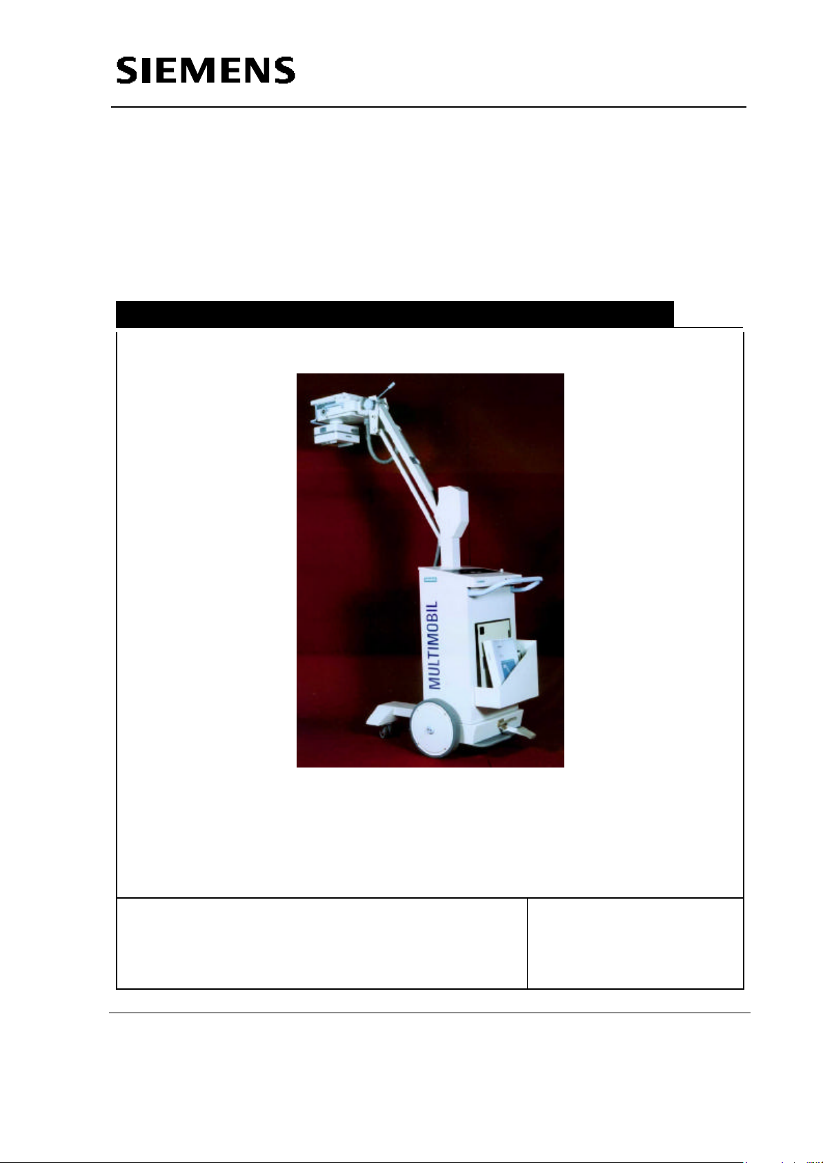
MULTIMOBIL 2.5
Troubleshooting Guide
SP
© Siemens AG 2005
The reproduction, transmission or
use of this document or its contents
is not permitted without express
written authority. Offenders will be
liable for damages. All rights,
including rights created by patent
grant or registration of a utility
model _or_ design,_are_ reserved.
English
Print No.: SPR8-X01.840.01.01.02 Doc. Gen. Date: 09.05
Replaces: n.a.
Page 2
Multimobil 2.5
Service Manual
Service Instructions
Med
Service Instructions
Version: 6.0
Copyright SIEMENS LTD.,MED INDIA
Siemens Ltd. Med India Version 6.0
Copyright SIEMENS LTD. All rights reserved. For internal use only
The reproduction, transmission or use of
this document or its contents is not
permitted without express written
authority. Offenders will be liable for
7-1
Page 3

Service Manual
Service Instructions
INDEX
7 SERVICE .........................................................................................................................7-3
7.1 TROUBLESHOOTING .......................................................................................................... 7-3
7.1.1 Tools and measuring instruments required...................................................................7-3
7.2 CONTROL VOLTAGES .......................................................................................................7-3
7.3 SIGNALS........................................................................................................................7-3
7.4 HT CHECK ..................................................................................................................... 7-4
7.5 CALIBRATION..................................................................................................................7-4
7.5.1 kVp Measurement.....................................................................................................7-4
7.5.2 mA / mAs Measurement ............................................................................................7-5
7.6 TROUBLESHOOTING .......................................................................................................... 7-5
7.6.1 Checking the line voltage ...........................................................................................7-5
7.6.2 Checking the fuses ...................................................................................................7-6
7.6.3 Checking the LEDs on D920......................................................................................7-6
7.7 CHECKING THE CONTROL VOLTAGES....................................................................................7-7
7.7.1 Checking the Intermediate circuit voltage....................................................................7-7
7.8 CHECKING & SETTING THE MAXIMUM MAIN INVERTER FREQUENCY ................................................7-7
7.9 FILAMENT CURRENT MEASUREMENT ......................................................................................7-8
7.10 CHECKING THE HIGH VOLTAGE KVSOLL AND KVIST ..................................................................7-8
7.11 SETTING THE MAXIMUM FILAMENT FREQUENCY ........................................................................7-8
7.12 CHECKING THE TUBE CURRENT.............................................................................................7-8
7.13 CHECKING THE KV AND TUBE CURRENT (JR)...........................................................................7-9
7.14 CHECKING THE MAS VALUES...............................................................................................7-9
7.15 ADJUSTING THE MAS......................................................................................................... 7-9
7.16 SWITCHING THE COLLIMATOR LIGHT ON................................................................................7-9
7.17 PROGRAM MODES FOR SERVICING. ......................................................................................7-9
7.17.1 Program 1.......................................................................................................... 7-10
7.17.2 Program 2.......................................................................................................... 7-10
7.17.3 Program 3.......................................................................................................... 7-10
7.17.4 Program 4.......................................................................................................... 7-10
7.17.5 Program 5.......................................................................................................... 7-10
7.17.6 Program 6.......................................................................................................... 7-11
7.17.7 Program 7.......................................................................................................... 7-11
7.18 CODES ...................................................................................................................... 7-12
7.19 SPECIFIC CODE HANDLING.............................................................................................. 7-13
7.19.1 Unit not turning ON.............................................................................................. 7-13
7.19.2 No Radiography................................................................................................... 7-15
7.19.3 No Standby........................................................................................................ 7-17
7.19.4 Initialisation CODEs............................................................................................ 7-18
7.19.5 Standby CODEs ................................................................................................. 7-20
7.19.6 EXPOSURE CODES........................................................................................... 7-27
7.20 PCB LAYOUT DRAWINGS ............................................................................................... 7-36
7.20.1 Master Card D915 ............................................................................................... 7-36
7.20.2 Interface PCB D920 ............................................................................................ 7-37
7.20.3 Inverter Card D61................................................................................................ 7-38
Siemens Ltd. Med India Version 6.0
Copyright SIEMENS LTD. All rights reserved. For internal use only
7-2
Page 4

Service Manual
Service Instructions
7 Service
7.1 Troubleshooting
7.1.1 Tools and measuring instruments required
• Usual service tools
• Digital multimeter
• 2 channel storage oscilloscope with 2 probes and 1 current probe
• mAs meter
• Protective ground wire and leakage current tester: Bender safety tester
• Radiation detector
During Oscilloscope operation the protective ground wire connection in the
power cable must not be interrupted under any circumstances.
For measurements where ground loops that may be present could impair the
measuring result, use the Tek amplifier and the trigger attachment .
CAUTION
7.2 Control Voltages
Voltage Measuring Point Range
+5 V D915.X15.4 4.8V to 5.2V
+15 V D915.X15.5 13.5V to 16.5V
-15 V D915.X15.7 -13.5V to –16.5V
+24 V(For Filament) D920 X4.7 &4.8 23 V to 25.5 V
Collimator Supply D920.X12A/B 12V ac to 16V ac
7.3 Signals
Signal Measuring Point Range Adjustment
Kvsoll D915.TP.KVS
2.0 ± 0.1 V for 60kV D915.P7
During Exposure
Masoll D915.TP.JRS
2 V ± 0.1 V for 60kV D915.P6
During Standby
Siemens Ltd. Med India Version 6.0
Copyright SIEMENS LTD. All rights reserved. For internal use only
7-3
Page 5
Service Manual
Presence of High Tension.
Service Instructions
Signal Measuring Point Range Adjustment
IH D915.TP. IH
D915.P5
During Standby 2 V ± 0.1 V
During Preparation 3.8 V ± 0.3 V (For critically
damped mA)
Fmax D915.TP.REG point
9.2 kHz ± 0.3 kHz D915.P4
during exposure
7.4 HT Check
WARNING
Use Radiation Protection.
7.5 Calibration
It is advisable to re-calibrate the unit in case of undershoot or overshoot observed in
the mA waveshape.
Recalibration is required when the single tank is replaced.
7.5.1 kVp Measurement
The kVp measurement can be carried out either by kVp-meter or by electrical
measurement.
7.5.1.1 kVp-meter
Switch the unit ON.
Insert the kV sensor into collimator channel and connect the cable to the meter.
Open collimator flaps such that the sensor is well covered by the field.
Set the kVp meter at 12pulse and 55-85kV range.
Set exposure parameters as 60kV 20mAs.
Release an exposure. The radiation LED will light up during exposure.
The meter will read 57-63kV.
Repeat with meter setting 77-150kV and exposure parameter setting as 90kV 20mAs.
The meter will read 85.5-94.5 kV.
7.5.1.2 Electrical
Connect oscilloscope at D915.TP.KV.
Set the exposure parameters as 60KV 2.5mAs.
Release an exposure.
The recorded waveform will read 2.85 - 3.15V.
Repeat with 90kV 1.6mAs.
The recorded waveform will read 4.27 - 4.75V.
Lower kV indicates error in kVsoll / kVsensing / kV-regulator OR high mA.
Siemens Ltd. Med India Version 6.0
7-4
Copyright SIEMENS LTD. All rights reserved. For internal use only
Page 6

Service Manual
Service Instructions
Higher kV indicates error in kVsoll / kV sensing / kV regulator.
7.5.2 mA / mAs Measurement
mAs measurement could be carried out either by mAs-meter or by electrical
measurement.
7.5.2.1 mAs-meter
Remove mAs link on D920.
Insert mAs-meter leads in the banana sockets mA+ and mA- on D920.
Set meter in the mAs mode at 200mAs.
Set exposure parameters as 60kV 20mAs.
Release an exposure.
The meter will read 19 - 21mAs.
Repeat for exposure parameters 90kV 16mAs.
The meter will read 14.4 to 17.6mAs.
The actual tube current can be measured by setting the meter in mA mode.
Set the exposure parameters as 60kV 50mAs.
Release an exposure.
During the exposure, the meter will read 23 - 27mA.
7.5.2.2 Electrical
Connect oscilloscope at D915.TP.JR.
Set exposure parameters as 60kV 2.5mAs.
Release an exposure.
The recorded waveform will read 1.58 - 1.62V.
The exposure time will be 76 - 84mS.
Lower mA indicates error in mAsoll / mAsensing / mA regulator circuit.
Higher mA indicates error in mAsoll / mA sensing / mA regulator OR Low kV.
Incorrect mAs indicates Error in timer.
7.6 Troubleshooting
In case of CODEs which Impair radiography, perform the following checks.
7.6.1 Checking the line voltage
Measure the supply voltage at site using the digital multimeter.
Ensure that the supply conditions
• Voltage
• Frequency
• Mains Resistance
are within limits as specified in the Technical Specifications for the Unit.
Switch the Unit ON
Siemens Ltd. Med India Version 6.0
Copyright SIEMENS LTD. All rights reserved. For internal use only
7-5
Page 7

Service Manual
Service Instructions
If the Unit can not be switched ON Check Supply at
Socket.Check Continuity of mains cable with the Plug
NOTICE
pins.Check Over Current Protective devices MCB and U1 & U2.
Switch the Unit OFF.
7.6.2 Checking the fuses
Open the front cover of the control unit .
Loosen the Fuse carriers which are mounted on the base of the control unit and check
the continuity of fuse link . If fuse link has responded for overcurrent replace the Fuse
Link.
Checking the fuses on D920
F1 0.25 AT T1 transformer primary
F2 0.630 AT 240 V for X-ray table.
F3 0.630 AT 24 V for K3,K4,K5 relays
F4 10 AF Collimator supply
F5 4 AT Filament circuit.
7.6.3 Checking the LEDs on D920
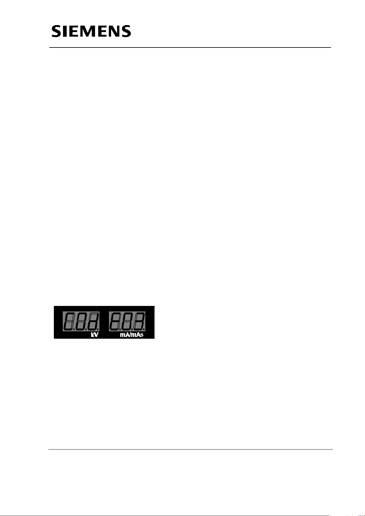
Switch the Unit ON.
After the initialisation, the default data 60 kV and 10 mAs are displayed at first time
switch ON or last stored kV & mAs value.
7.6.3.1 Standby mode
On D920 the following LEDs are illuminated :
V3 Main line voltage 240 V.
V9 Presence of 240V.
V12 Presence of 24 V for relay
V15 Presence of 12 V for collimator
V25 Presence of 24V for filament circuit
7.6.3.2 Preparation ON
On half press of exposure release switch unit should go in preperation mode.
In addition, V22 (green) lights up on D915.
7.6.3.3 Exposure Mode
On the second step of exposure release switch ,unit enters in radiograpy mode.
In addition, V23 (green) for exposure lights up on D915.
7.6.3.4 CODE message
Siemens Ltd. Med India Version 6.0
Copyright SIEMENS LTD. All rights reserved. For internal use only
7-6
Page 8
Service Manual
Service Instructions
V24 (red) lights up on D915 and CODE no. will be displayed on 7 segment display.
This will alternate with the kV and mAs values selected.
7.7 Checking the Control Voltages
When the unit is ON relay K2 on D920 are ON.
SMPS placed in the Inverter module gets supply, Measure the DC voltages at X15
connector of D915 PCB.
Pin No. Signal Name Input/Output max. permissible
voltage/current
1 D gnd Input 0V
2 -nc- -nc- 3 D gnd Input 0V
4 DC supply Input + 5V
5 DC supply Input +15V
6 A gnd Input 0V
7 DC supply Input -15V
-nc- = No Connection
7.7.1 Checking the Intermediate circuit voltage
Depending on the supply voltage, a value between 250 to 350Vdc must be measured
with the digital multimeter across the parallel capacitors C1,C2,C6,C7 and C9(if
present) in inverter module.
7.8 Checking & setting the maximum main inverter frequency
Turn the Unit OFF.
Place the ST link on D915 so as to short the two terminals.
Make the unit ON. The unit enters SERVICE mode.
In the service mode of the unit ,select Prog 7 by using the KV switches.
On activation of this mode by pressing the DL-serv Key , the display indicates
Adj F
Press the Radiographic exposure switch and monitor REG on Digital storage
Oscilloscope at Reg Test Points.
The display indicates
F On
And max. Inverter firng frequency will be displayed on Oscilloscope.
Adjust REG for 9.2 kHz ±0.3kHz by using P4 on D915 card
After adjusting the frequency switch off the unit and remove ST link on D915 card .
Siemens Ltd. Med India Version 6.0
Copyright SIEMENS LTD. All rights reserved. For internal use only
7-7
Page 9
Service Manual
Service Instructions
Fmax= 9.2 ± 0.3 kHz.
Adjust the maximum main inverter frequency with potentiometer P4 on D915
Turn the Unit OFF.
Connect 9 pin D-type connetor on D920 PCB.
7.9 Filament current measurement
Turn the Unit OFF.
Connect oscilloscope to D915.TP.IH
Turn the Unit ON.
After approx. 3 seconds the Stand-by filament current starts & equal to 2V ± 0.2V
Trigger exposure with default values for kV and mAs.
Observe the change in voltage level from 2 V ± 0.2V to Preheat value approx
3.8V ± 0.3 V.
Note : Preheat value is parameter (kV & mAs) specific. Just observe the change in
level on preheating step.
7.10 Checking the high voltage kVsoll and kVist
Connect oscilloscope to D915.TP.KVS & D915.TP.KV
Turn the unit ON.
Trigger an exposure with the default values.
Observe the voltage on C.R.O with the scale corresponding to 1V= 20kV for KV
and 1V =30KV for 30 KVS.
7.11 Setting the Maximum filament frequency
Turn the Unit OFF.
Remove X11 D915.
Connect oscilloscope to D915.TP.CAL
Turn the unit ON
``
Wait for the contactor to pick up.Press the DL_serv key on the D936 twice.
Using P3, set the maximum filament frequency on D915 (1.8 KHz to 2.2 KHz))
Note : Duty Cycle of the waveform is varying as the ON time is fixed.
Turn of the Unit.Replace X11 connector on D915 PCB.
7.12 Checking the tube current
Connect oscilloscope to D915.TP.JRS & D915.TP.JR
Turn the unit ON.
Trigger an exposure with the default values.
Observe the voltage on CRO (1V = 20mA) & confirm value for selected kV & mAs.
Siemens Ltd. Med India Version 6.0
Copyright SIEMENS LTD. All rights reserved. For internal use only
7-8
Page 10
Service Manual
Service Instructions
7.13 Checking the kV and tube current (JR)
Connect oscilloscope to D915.TP.KV & D915.TP.JR
Turn the unit ON.
Trigger an exposure with the default values.
Observe the voltage on CRO (1V = 20mA & 1V=20kV) for selected kV & mAs .
7.14 Checking the mAs values
Turn the Unit OFF.
Remove the Shorting Link “mAs +/-” on D920 PCB banana sockets.
Connect mAs meter to “mAs +/ mAs-” on D920 PCB.
Turn the Unit ON.
Trigger the following exposures:
Setting at control panel Valid mAs values
40kV,200 mAs 190..210 mAs
66kV,100mAs 95...105 mAs
90kV,1mAs 0.9.....1.1mAs
Turn the Unit OFF.
Remove the mAs meter and reinsert the Link on the D920 PCB.
7.15 Adjusting the mAs
Turn the Unit OFF.
Remove the Shorting Link “mAs +/-” on D920 PCB banana sockets.
Connect mAs meter to “mAs +/ mAs-” on D920 PCB.
Turn the unit ON.
Trigger the exposures for default kv & mAs settings.
Observe the mAs meter reading and if it is not within the tolerance (specified in the
Technical Specifications) of set value adjust the P1 on D915 card
7.16 Switching the Collimator Light ON
Switch ON Collimator Lamp. The Halogen lamp will light up and field of light will appear
on the target. The lamp will be switched OFF automatically after 30 seconds.
If the collimator lamp is switched ON and OFF several times within a short
period, overload protection will automatically switch the light OFF. Cool-down periods
are recommended.
7.17 Program Modes for servicing.
To put the Unit into service Mode short the ST link on the D915 and turn ON the unit
.The display will show as follows
Siemens Ltd. Med India Version 6.0
Copyright SIEMENS LTD. All rights reserved. For internal use only
7-9
Page 11
Service Instructions
Use the KV + or KV – switch to move to any program (PR 1 to PR7)
Use the DL_Serv switch on the D936 to to select the displayed program.
7.17.1 Program 1
Not Used
1. Short the ST link on the D915 and put the unit on .
the display will read as below and enter program mode .
Pr 1
2. This program is not used
7.17.2 Program 2
To check the total number of exposures taken .
Service Manual
1.The display on the D932 will be as below.
XXX XXX
XXX XXX corresponds to the total number of exposures taken on the unit.
7.17.3 Program 3
To check the type of codes that occurred in the unit (maximum 20) .
1.Press the switch DL-serv on the D936 once.The display will be
AA XX
AA diplays the serial number of the exposures that have occured, in chronological
order (max. 20) & XX displays the corresponding codes occured on the unit
7.17.4 Program 4
To erase the codes that occurred in the unit
1.Press the switch DL-serv on the D936 once.The display will be
ErA Err
Keep the mAS – key depressed for 4 seconds till the dislay beomes
0 Err
7.17.5 Program 5
To store the Last Value of KV & mAS Display
Siemens Ltd. Med India Version 6.0
Copyright SIEMENS LTD. All rights reserved. For internal use only
7-10
Page 12

Service Manual
Service Instructions
LAS VAL
By entering into this program the last value displayed before turning OFF the Unit will
be displayed on turn it On the next time .
7.17.6 Program 6
To Display the maimum KV & mAS possible with the Unit
100 200
100 indicates the maximum KV available & 200 indicates the maximum mAS
available on the Unit
*I n case the display values do not vary in standby by using the key PCB then
Enter this program and vary the KV & mAs displayed using the Key PCB D936
Then switch the the Unit OFF and enter standby mode, the unit should function
normally .
7.17.7 Program 7
Adjusting REG frequency.
Please refer chapter 7.8 (Checking & setting the maximum main inverter frequency)
Siemens Ltd. Med India Version 6.0
Copyright SIEMENS LTD. All rights reserved. For internal use only
7-11
Page 13

Service Manual
Service Instructions
7.18 CODEs
Initialisation Codes
90 EPROM Checksum
Failure
96 kVsoll Failure During Self Diagnostics the software outputs 7Fh to the D/A converter (B).
97 JRS Failure During Self Diagnostics the software outputs 7Fh to the D/A converter (A).
99 Last Reset by watchdog
Timer
02 +15V Supply error The +15V supply from SMPS is polled by the µC through Analog port 0. The
03 Iheiz < Istby The Filament Standby current is 2A. Iheiz read by the µC through Analog port
04 Iheiz > Istby The maximum value of Standby current permitted is 2.2 A.
05 kVist <> 0 kVist is read by the µC through Analog port 7. During Standby the value of
06 JR <> 0 JR is read by the µC through Analog port 1. During Standby the value of JR
33 Main Inverter Short Circuit In standby mode if the Main Inverter Driver (Cable) is disconnected this
11 Main Inverter Short Circuit This CODE is displayed when short circuit is detected by the drivers of the
12 kVist > kVmax The PkV is monitored for Max.110kV. If the actual value of kV is greater than
13 Iheiz > Imax OR JR >
Jrmax
14 kVist < kVsoll kVist is continuously polled during exposure. The value of kVist should be
15 JR < JRS JR is continuously polled during exposure. The value of JR should be
17 Backup Timer This CODE is displayed if regular means of terminating exposure fails and
18 Premature Exposure
Termination
The EPROM Checksum is stored at 7FFEh and 7FFFh as a 16 bit word.
During self Diagnostics the software calculates the checksum of the EPROM
and compares with the stored checksum.
The 2.5V at the output of the D/A converter is Read by the µC through Analog
Port 4. The value read should be greater than 7Ah and less than 86h. (I.e.
between 2.39V and 2.62V)
The 2.5V at the output of the D/A converter is Read by the µC through Analog
Port 3. The value read should be greater than 7Ah and less than 86h. (I.e.
between 2.39V and 2.62V)
The built-in Watchdog timer (WDT) is reset by the software every 25 msec. If
due to some failure the software doesn’t reset the WDT, the WDT in turn will
reset the µC after 65 msec.
Standby CODEs
+15V supply should be between +12V to +18V.
2 should be greater than 1.75A. i.e. 1.75V (Iheiz ratio : 1V = 1A)
kVist read should be Zero. (kVist ratio : 1 V = 20kV)
read should be Zero. (JR ratio : 1 V = 20mA)
CODE gets activated.
Exposure CODEs
Main Inverter.
this i.e. if the voltage cross 3.73V CODE is displayed.
Maximum value of Iheiz above which CODE will be displayed is 4.4 A (4.4V).
Maximum value of mAist above which CODE is displayed is 71mA. (3.59V)
greater than 85% of kVsoll
greater than 50% of JRS.
exposure gets terminated by the backup timer. Exposure time is set for (Exp
+ Exp/4) for less than 100 ms and (Exp +Exp/10) for greater than 100 ms
Exposure Release Switch is released before the exposure is terminated by
the mAs Integrator.
Siemens Ltd. Med India Version 6.0
Copyright SIEMENS LTD. All rights reserved. For internal use only
7-12
Page 14

Service Manual
Service Instructions
21 I > Iheiz This CODE is displayed if the filament current exceeds 4.1V in prepation
state.
22 Maximum Preparation
Time
This CODE is displayed if First step is pressed for more than 15 sec.
7.19 Specific CODE Handling
7.19.1 Unit not turning ON
Siemens Ltd. Med India Version 6.0
Copyright SIEMENS LTD. All rights reserved. For internal use only
7-13
Page 15

Service Manual
Service Instructions
Siemens Ltd. Med India Version 6.0
Copyright SIEMENS LTD. All rights reserved. For internal use only
7-14
Page 16

7.19.2 No Radiography
Service Manual
Service Instructions
Siemens Ltd. Med India Version 6.0
Copyright SIEMENS LTD. All rights reserved. For internal use only
7-15
Page 17

Service Manual
Service Instructions
Siemens Ltd. Med India Version 6.0
Copyright SIEMENS LTD. All rights reserved. For internal use only
7-16
Page 18

7.19.3 No Standby
Service Manual
Service Instructions
Siemens Ltd. Med India Version 6.0
Copyright SIEMENS LTD. All rights reserved. For internal use only
7-17
Page 19

7.19.4 Initialisation CODEs
CODE 90 (EPROM CHECKSUM FAILURE)
CODE 96 (KV SOLL FAILURE)
CODE 97 ( mA FAILURE)
CODE 99 (LAST RESET BY WATCH DOG TIMER)
Service Manual
Service Instructions
Siemens Ltd. Med India Version 6.0
Copyright SIEMENS LTD. All rights reserved. For internal use only
7-18
Page 20

Service Manual
Service Instructions
Siemens Ltd. Med India Version 6.0
Copyright SIEMENS LTD. All rights reserved. For internal use only
7-19
Page 21

7.19.5 Standby CODEs
7.19.5.1 CODE 02 : +15 V Supply CODE
Service Manual
Service Instructions
Siemens Ltd. Med India Version 6.0
Copyright SIEMENS LTD. All rights reserved. For internal use only
7-20
Page 22

7.19.5.2 CODE 03: Iheiz < Istby
Service Manual
Service Instructions
Siemens Ltd. Med India Version 6.0
Copyright SIEMENS LTD. All rights reserved. For internal use only
7-21
Page 23

Service Manual
Service Instructions
Siemens Ltd. Med India Version 6.0
Copyright SIEMENS LTD. All rights reserved. For internal use only
7-22
Page 24

7.19.5.3 CODE 04: Iheiz > Istby
Service Manual
Service Instructions
Siemens Ltd. Med India Version 6.0
Copyright SIEMENS LTD. All rights reserved. For internal use only
7-23
Page 25

7.19.5.4 CODE 05 : kVist <> 0
Service Manual
Service Instructions
Siemens Ltd. Med India Version 6.0
Copyright SIEMENS LTD. All rights reserved. For internal use only
7-24
Page 26

7.19.5.5 CODE 06 : JR <> 0
Service Manual
Service Instructions
Siemens Ltd. Med India Version 6.0
Copyright SIEMENS LTD. All rights reserved. For internal use only
7-25
Page 27

7.19.5.6 CODE 33 : Main Inverter Short Circuit
Service Manual
Service Instructions
Siemens Ltd. Med India Version 6.0
Copyright SIEMENS LTD. All rights reserved. For internal use only
7-26
Page 28

7.19.6 EXPOSURE CODES
7.19.6.1 CODE 11 : Main Inverter Short Circuit
Service Manual
Service Instructions
Siemens Ltd. Med India Version 6.0
Copyright SIEMENS LTD. All rights reserved. For internal use only
7-27
Page 29

7.19.6.2 CODE 12 : kVist > kVmax
Service Manual
Service Instructions
Siemens Ltd. Med India Version 6.0
Copyright SIEMENS LTD. All rights reserved. For internal use only
7-28
Page 30

7.19.6.3 CODE 13 : Iheiz > Imax OR JR > Jrmax
Service Manual
Service Instructions
Siemens Ltd. Med India Version 6.0
Copyright SIEMENS LTD. All rights reserved. For internal use only
7-29
Page 31

7.19.6.4 CODE 14 : kVist < kVsoll
Service Manual
Service Instructions
Siemens Ltd. Med India Version 6.0
Copyright SIEMENS LTD. All rights reserved. For internal use only
7-30
Page 32

7.19.6.5 CODE 15 : JR < JRS
Service Manual
Service Instructions
Siemens Ltd. Med India Version 6.0
Copyright SIEMENS LTD. All rights reserved. For internal use only
7-31
Page 33

7.19.6.6 CODE 17 : Exposure terminated by Backup Timer
Service Manual
Service Instructions
Siemens Ltd. Med India Version 6.0
Copyright SIEMENS LTD. All rights reserved. For internal use only
7-32
Page 34

7.19.6.7 CODE 18 : Premature termination of Exposure
Service Manual
Service Instructions
Siemens Ltd. Med India Version 6.0
Copyright SIEMENS LTD. All rights reserved. For internal use only
7-33
Page 35

7.19.6.8 CODE 21 : Iheiz > Iheiz maximum
Service Manual
Service Instructions
Siemens Ltd. Med India Version 6.0
Copyright SIEMENS LTD. All rights reserved. For internal use only
7-34
Page 36

7.19.6.9 CODE 22 : Maximum Preparation Time
Service Manual
Service Instructions
Siemens Ltd. Med India Version 6.0
Copyright SIEMENS LTD. All rights reserved. For internal use only
7-35
Page 37

7.20 PCB Layout Drawings
7.20.1 Master Card D915
Service Manual
Service Instructions
Siemens Ltd. Med India Version 6.0
Copyright SIEMENS LTD. All rights reserved. For internal use only
7-36
Page 38

7.20.2 Interface PCB D920
Service Manual
Service Instructions
Siemens Ltd. Med India Version 6.0
Copyright SIEMENS LTD. All rights reserved. For internal use only
7-37
Page 39

7.20.3 Inverter Card D61
Service Manual
Service Instructions
Siemens Ltd. Med India Version 6.0
Copyright SIEMENS LTD. All rights reserved. For internal use only
7-38
 Loading...