

Page 1

MULTIMOBIL 2.5
Pre-Installation
SP
© Siemens AG 2003
The reproduction, transmission or
use of this document or its contents
is not permitted without express
written authority. Offenders will be
liable for damages. All rights,
including rights created by patent
grant or registration of a utility
model _or_ design,_are_ reserved.
English
Print No.: SPR8-X01.811.01.02.02 Doc. Gen. Date: 09.05
Replaces: SPR8-X01.811.01.01.02
Page 2
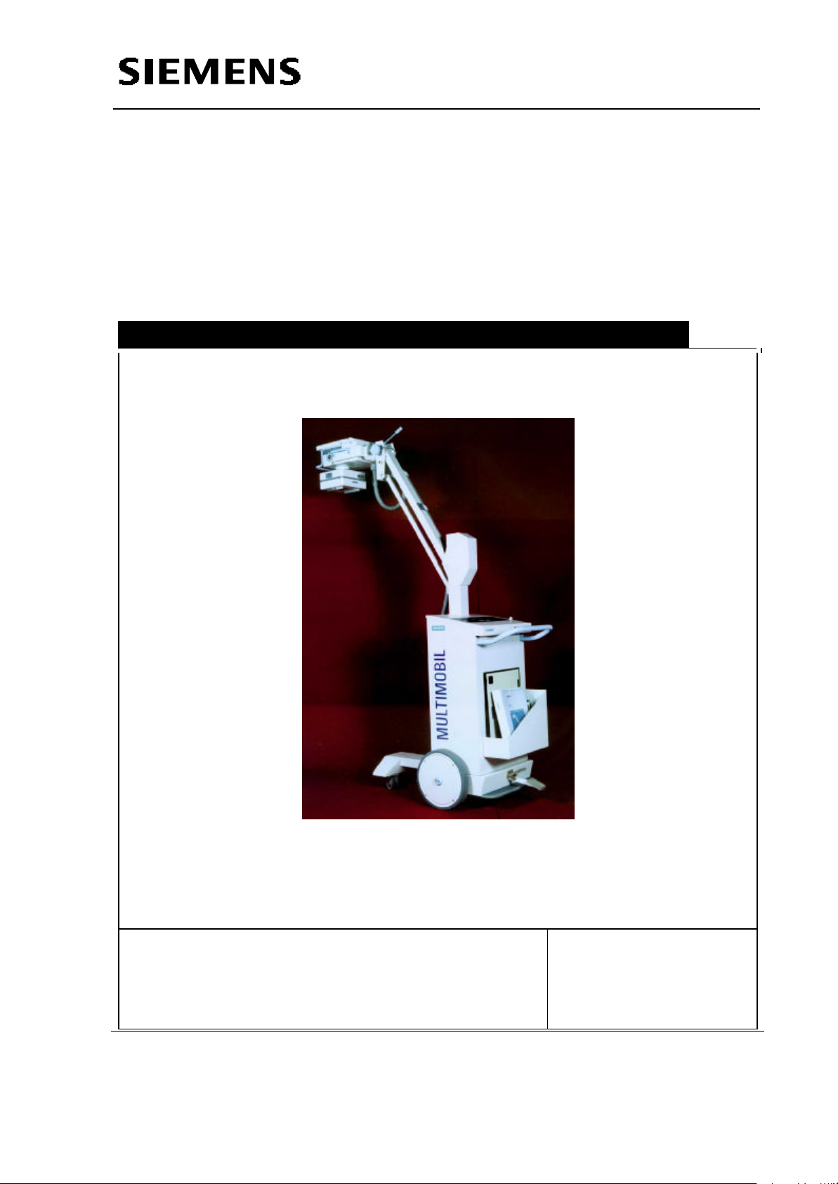
Multimobil 2.5
Service Instructions
Pre-installation Instructions
Med
Pre-installation Instructions
Version: 6.0
Copyright SIEMENS LTD., Med INDIA
Siemens Ltd. MED Division India Version 6.0
Copyright SIEMENS LTD. All rights reserved. For internal use only
The reproduction, transmission or use
of this document or its contents is not
permitted without express written
authority. Offenders will be liable for
damages.
1-1
Page 3

Service Instructions
Pre-installation Instructions
INDEX
1 PRE INSTALLATION........................................................................................................1-3
1.1 TECHNICAL SPECIFICATIONS ......................................................................................1-3
1.2 INFORMATION FOR ROOM PLANNING.....................................................................................1-5
1.3 EXPOSURE CHART...........................................................................................................1-6
Siemens Ltd. MED Division India Version 6.0
Copyright SIEMENS LTD. All rights reserved. For internal use only
1-2
Page 4

1 Pre Installation
1.1 TECHNICAL SPECIFICATIONS
Sr.No Parameter Value
1. Rated Mains Voltage 190 - 240 V~
2. Line frequency 50 Hz , ± 2 Hz
3. Line fuses 16 A delayed fuse.
4. Line impedance 1.5 Ω max
5. Length of power cable 5 m
6. Power Output
Nominal Electric power at
100kV and 100mSec.
7. Wave Shape Multipulse - Ripple 5kV max
2.5 kW (100 kV, 25 mA)
Service Instructions
Pre-installation Instructions
8. kVp Range 40 - 100kV in 20 steps
9. Nominal kV 100 kV for DSA-7, SR 100/20 & FA
100/20
110 kV for OX 110-1
10. kV Accuracy ≤ ± 5 %
11. mA-range 13 – 63 mA
12. mAs Range 0.32 - 200mAs at 40kV
13. 0.32 - 160mAs at 42 - 50kV
14. 0.32 - 125mAs at 52 - 63kV
15. 0.32 - 100mAs at 66 - 77kV
16. 0.32 - 80 mAs at 81 - 100kV
For details of kV, mA and exposure
time combinations as per IEC 606012-7 refer to the exposure chart on page
1-6.
17. mAs Accuracy ≤ 10 % + 0.2 mAs for mAs ≤ 20 mAs
≤ 5 % + 0.2 mAs for mAs > 20 mAs
18. Exposure Time 20mSec - 5 Sec in 24 steps
19. X - ray Tube Stationary Anode
DSA –7 / OX 110-1 / SR100/20 / FA
100/20
20. Focal Spot – nominal value 1.4 IEC-336 for DSA-7
1.5 IEC-336 for OX/110-1
Siemens Ltd. MED Division India Version 6.0
Copyright SIEMENS LTD. All rights reserved. For internal use only
1-3
Page 5

Service Instructions
Pre-installation Instructions
Sr.No Parameter Value
1.4 IEC-336 for SR 100/20
1.4 IEC-336 for FA 100/20
21. Anode angle 14° for DSA –7
19 ° for OX/110-1
14° for SR 100/20
14° for FA 100/20
22. Inherent Tube Filteration 1.5 mm Al for DSA -7
0.5 mm Al for OX/110-1
1.5 mm Al for SR 100/20
0.9 mm Al for FA 100/20
Refer to the tube data sheet.
23. Application Radiographic operation, according to
exposure table
24. Mode of Operation Continuous operation with intermittent
loading
25. Collimator Manually adjustable, Double Slot
26. Light localizer Halogen light Bulb12V, 100 W; 100
Lux at 1m SID .
27. SID range Min: 520mm (+/- 20mm)
Max: 1960mm (+/- 20mm)
28. Light Field at 1 m SID 17“ X 17“
29. Max. cassette size at 1m SID 17“ X 17“
30. X-ray coverage at 1m SID 17“ X 17“
31. Total Filteration of the X-ray
source assembly with
collimator
3.0 mm Al for DSA –7
2.8 mm Al for OX 110-1
3.4 mm Al for SR 100/20
3.0 mm of Al for FA 100/20
32. Exposure Switch 2 Step, 5m cable
33. Exposure Rate Pulse-to-pause ratio 1:30; corresponds
to a cool down period of 3 minutes at
maximum output.
34.
35. Mains Isolation
Siemens Ltd. MED Division India Version 6.0
Power Input :
Momentary input
Long-time input
3.00 KVA. (± 10%)
0.5 KVA. (± 10%)
Power supply cord shall be
plugged in where Both poles (L &
1-4
Copyright SIEMENS LTD. All rights reserved. For internal use only
Page 6

Service Instructions
Pre-installation Instructions
Sr.No Parameter Value
External : done by the user.
N) are isolated simultaneously
using ON/OFF switch with
protective earth.
36. Cassette Compartment Maximum space
37. Weight
Total without Packing approx. 147 kg.
Total with Packing approx. 245 kg.
38. Max. floor incline for transport 5°
39. Type and degree of protection
Class – I , Type B Equipment.
against electrical shock
1.2 Information for Room Planning
No specific conditions required. Following are the recommended room conditions for
proper functioning of the unit.
Ambient Temperature (Room temperature):Min – 20 °C, Max + 40 °C
Air Humidity: in the range of 30% to 75%, Non-condensing.
During Transport and storage of all products the ambient temperature should not be
below -20°C or rise above +55°C. Storage is permissible in rooms with minimum
amount of dust and Humidity Upto 95% RH provided no condensation occurs.
Siemens Ltd. MED Division India Version 6.0
Copyright SIEMENS LTD. All rights reserved. For internal use only
1-5
Page 7

1.3 Exposure Chart
Service Instructions
Pre-installation Instructions
Siemens Ltd. MED Division India Version 6.0
Exposure Chart
1-6
Copyright SIEMENS LTD. All rights reserved. For internal use only
 Loading...