

Page 1
MULTIMOBIL 2.5
Installation Instructions
SP
© Siemens AG 2003
The reproduction, transmission or
use of this document or its contents
is not permitted without express
written authority. Offenders will be
liable for damages. All rights,
including rights created by patent
grant or registration of a utility
model _or_ design,_are_ reserved.
English
Print No.: SPR8-X01.812.01.02.02 Doc. Gen. Date: 09.05
Replaces: SPR8-X01.812.01.01.02
Page 2
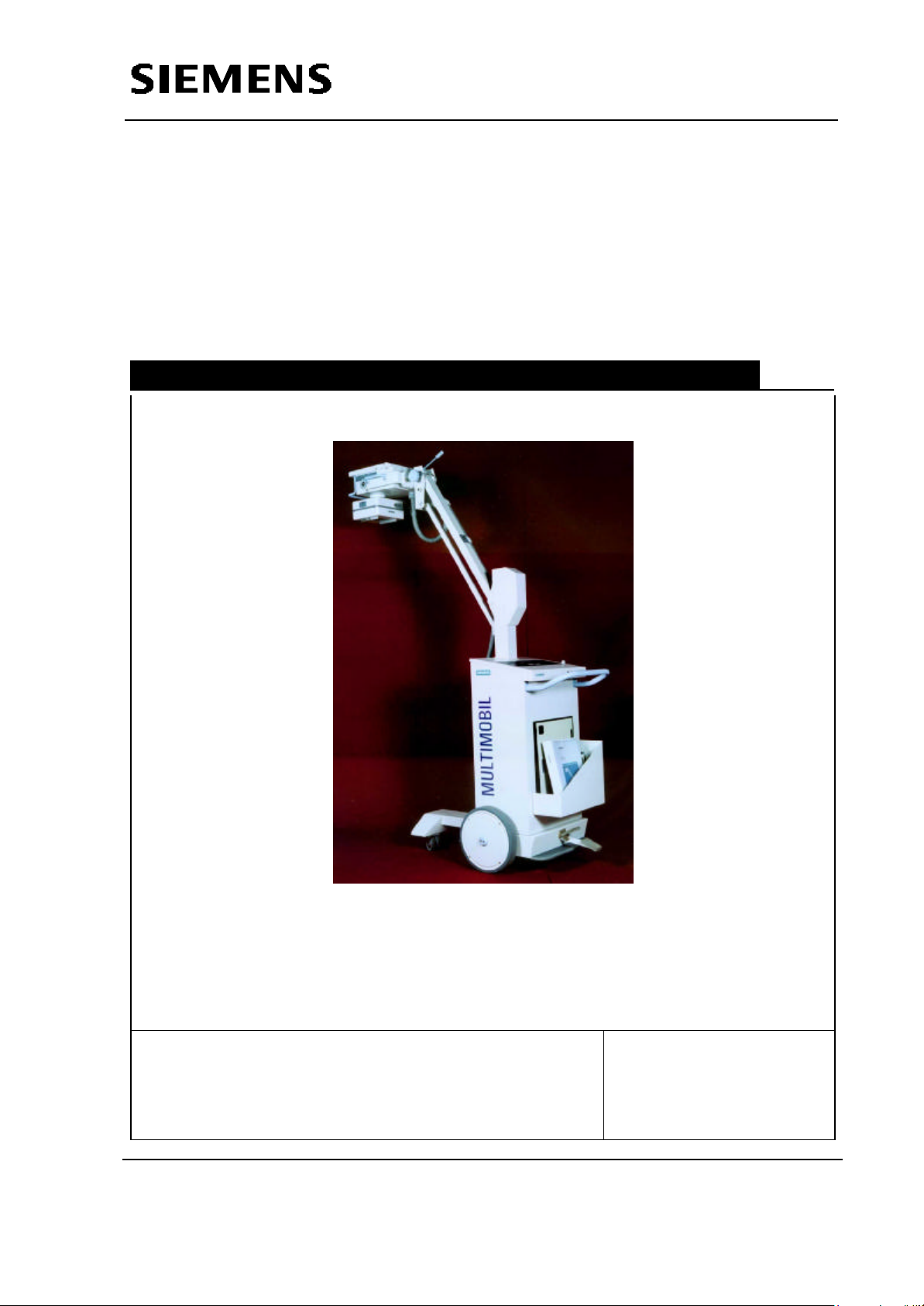
Multimobil 2.5
Service Manual
Installation Instructions
Med
Installation Instructions
Version: 6.0
Copyright SIEMENS LTD.,MED INDIA
Siemens Ltd. Med India Version 6.0
Copyright SIEMENS LTD. All rights reserved. For internal use only
The reproduction, transmission or use
of this document or its contents is not
permitted without express written
authority. Offenders will be liable for
damages.
2-1
Page 3

Service Manual
Installation Instructions
INDEX
2 INSTALLATION INSTRUCTIONS ......................................................................................2-3
2.1 SAFETY PRECAUTIONS .....................................................................................................2-3
2.2 OVERLOAD PROTECTION...................................................................................................2-3
2.3 RADIATION PROTECTION....................................................................................................2-4
2.4 MECHANICAL SAFTEY.......................................................................................................2-4
2.5 UNPACKING ................................................................................................................2-5
2.6 TRANSPORT AND POSITIONING OF UNIT.................................................................................2-6
2.7 PRELIMINARY CHECK ........................................................................................................2-6
2.7.1 Mains...................................................................................................................2-6
2.7.2 Interconnections ...................................................................................................2-6
2.7.3 Switching ON ........................................................................................................2-7
2.8 FORMING .......................................................................................................................2-7
2.9 COLLIMATOR ..................................................................................................................2-8
2.10 MOVEMENTS...............................................................................................................2-8
2.11 EXPOSURE.................................................................................................................2-8
2.11.1 Timing..................................................................................................................2-9
Siemens Ltd. Med India Version 6.0
Copyright SIEMENS LTD. All rights reserved. For internal use only
2-2
Page 4

Service Manual
Installation Instructions
2 Installation Instructions
2.1 Safety Precautions
It shall be the duty of the installation personnel and the user to ensure that all the safety
measures concerning the unit operation and installation are adhered to.
The unit must be checked for the status of its safety measures at least every year or
any time desired by the user, not exceeding one year.
However, we recommend in the interest of the safety of the patient, the user, and other
personnel to have a yearly drill on operational safety.
If there are any special regulations of the hospital/institute, to be followed over and
above the general safety regulations pertaining to the installation, the same must be
ensured.
Before commencing the operation, the user must convince himself/herself all safety
aspects and their proper functioning. He should also ascertain that all displays and
indicators are functioning as described.
The radiation indication lamp should light only when the exposure is released. In case
the lamp lights in any other condition, the unit should be immediately switched off and
SIEMENS SERVICE DEPARTMENT should be informed.
Any change / or replacement in the unit must be carried out by the manufacturer or a
person authorised by manufacturer ONLY. The record of such work must be
maintained clearly at the site.
Before working on the unit ensure that the Mains is switched OFF.
For completely safe working remove mains plug.
The unit must be OFF before removing or putting back the assemblies.
The protective earthing of subassemblies must not be removed in any case.
2.2 Overload Protection
The unit is designed to work on 190 – 240V,50Hz 15A socket. For safety purposes
16A HRC fuses are provided which will blow when a current exceeding 16A sustains
for its response time.
CAUTION
Ensure that the mains socket is properly earthed.
Siemens Ltd. Med India Version 6.0
Copyright SIEMENS LTD. All rights reserved. For internal use only
2-3
Page 5

Service Manual
Installation Instructions
In case of fault, if the kV tries to build beyond the safe limit of X-ray tube the protection
circuit blocks the HT.
In case of fault, if the Filament current tries to increase beyond the safe limit the
protection circuit blocks filament boosting.
2.3 Radiation Protection
WARNING
Do not put any part of your body in the direct line of radiation.
Collimate the X-ray beam.
Keep maximum possible distance from the object being radiographed. For this
make the best use of 5 m of recoilable exposure release switch.
Wear protective clothing.
Monitor radiation received using the personal TLD-badges or pen-dosimeter.
2.4 Mechanical Saftey
Before releasing arm assembly from its locking position, ensure that the single tank
assembly along with covers, yoke and collimator is in the original position.
In case a difficulty is encountered in releasing the lock, any adjustments or alignments
must be done with complete single tank assembly in the locked position only.
CAUTION
Do not attempt to release the lock by any other means.
The arm will not be counter-balanced if any of the single tank assembly parts like cover
are removed.
Any detection of physical damage of single tank assembly or breaking or loosening of
its parts (except handles) indicates possible danger of upward force, the order of
25kg, when the arm is released from its locked position. In such a situation, it is
recommended to suspend the installation and contact FACTORY for further
clarification.
Siemens Ltd. Med India Version 6.0
Copyright SIEMENS LTD. All rights reserved. For internal use only
2-4
Page 6

2.5 UNPACKING
Service Manual
Installation Instructions
Siemens Ltd. Med India Version 6.0
Copyright SIEMENS LTD. All rights reserved. For internal use only
2-5
Page 7

Service Manual
Installation Instructions
After opening the case, locking arrangement of rear wheels must be checked before
the safety blocks are removed.
The complete system must be inspected for physical damage and / or material shortfall
and factory must be informed accordingly
2.6 Transport and Positioning of Unit
Refer corresponding section on Transporting the Unit and Positioning for Exposures in
the Operating Instructions.
2.7 Preliminary Check
2.7.1 Mains
1. Check available mains voltage at the site.
2. Check if the mains voltage is within nominal range of 190 – 240V ac.
3. Check if the Mains resistance is ≤ 1.5 Ω.
2.7.2 Interconnections
Type Description Specifications
Mains 1 Mains Cable 3 x 1.5 mm sq.
Control to single
Tank
HT Cables U & V 2.5 mm sq. Yellow
Filament cables 12 & Y 2 Core shielded PVC insulated
Collimator Cable 2 Core 1 mm sq. Grey
Earth Cable 6 mm sq. Yellow-Green
kV feedback Cable 2 Core shielded PVC insulated
Ground Wire (X) 1.5 mm sq. Yellow
Interconnections D915.X20 to D920.X20 20p FRC
D915.X10 to D920.X10 26p FRC
D915.X11 to D920.X11 16p FRC
D915.X12 to D936.X12 14p FRC
D915.J24 to D932.X1 28p DIP FRC
D915.X8 to D920.X8 10p Bonded
D915.X15 to D980.X7 5p Bonded + Earth
D920.X6 to D61.X6 D type soldered connections
D920.X27 to S27 3 Core cable
D920.X1 to T1 input Bunch
D920.X4 to T1 output Bunch
D920.X2 to Single Tank Bunch
Wire Bunch
Siemens Ltd. Med India Version 6.0
Copyright SIEMENS LTD. All rights reserved. For internal use only
2-6
Page 8

Service Manual
Green LED V1 on D61.
Installation Instructions
Maximum permissible resistance between the earthing lead terminal in the control and
on the HT transformer shall not exceed 0.2 ohms.
2.7.3 Switching ON
Switch on the MCB to position
the control housing.
Switch the Generator ON by actuating
momentarily on the overlay of the top panel.
The Display and radiation Indicator light up for 3.5 seconds
In the kV and mAs fields as shown in
Figure for 3.5 seconds.
Then the stable kV and mAs values appear.
9 seconds after that the unit becomes ready for use and the same is indicated by a
long Beep at the end of setup.
In case of any errors while setting up / hardware check / stand-by operation, the
corresponding Error code will be displayed on the same displays. For troubleshooting
of this error refer services Instructions.
NOTICE
The Control Unit contains Non volatile Memory,
which retains the last selected kV and mAs. So the
initial display after setup will depend on the last
settings done.
After the unit is switched on, the capacitors
C1/C2/C6/C7/C9 charge to 300VDC. After switching the
CAUTION
unit OFF, it takes about 8 minutes for capacitors to
discharge. The presence of DC voltage is indicated by
2.8 Forming
If the unit is being installed after six months from the date of despatch, the capacitors
C1/C2/C6/C7/C9 need forming.
On capacitors V+ and V- maintain only following connections.
Siemens Ltd. Med India Version 6.0
Copyright SIEMENS LTD. All rights reserved. For internal use only
2-7
Page 9

V1+ C1+,C2+,C6+,C7+,C9+*,R3
Observe Safety Precautions
V1- C1 -, C2-,C6-,C7-,C9 -*, R3
*C9 Present only if 16000MFD capacitors are used
Connect DC Voltmeter across C+ & C-.
Disconnect wires from AC input of
rectifier V1. Connect variable power
supply 0 - 250V AC to V1 AC input with
1kΩ / 50W resistor in series.
Increase voltage slowly till Vc reads
100V.
Maintain for 15 minutes. Note Vc.
Increase voltage till Vc reads 195V.
Maintain for 10 minutes.
Increase voltage till Vc reads 300V.
Maintain for 10 minutes.
Service Manual
Installation Instructions
2.9 Collimator
Switch the unit ON
Switch ON the collimator lamp. The collimator lamp will glow for 30 sec ± 5 sec.
Open collimator flaps to the maximum. The light will show square, sharp edges and
clear cross wires.
Close the flaps fully. The light field will show a small square.
2.10 Movements
Check arm counterbalancing at all positions.
When the single tank does not remain at the required position, the spring tension
should be adjusted for complete balancing.
Refer Troubleshooting instructions for adjustments of spring tension.
Use Radiation Protection
WARNING
Presence of High Tension
2.11 Exposure
Switch the generator ON.
Set exposure parameters as 60KV, 10mAs.
Pull the recoilable exposure release switch and release an exposure.
The yellow LED on top panel lights up for a short duration equal to exposure time.
Audible indication by a Buzzer from the control and muffled sound from inverter
confirms the working of the inverter.
The LED’s on D915 light in the following sequence:
Siemens Ltd. Med India Version 6.0
2-8
Copyright SIEMENS LTD. All rights reserved. For internal use only
Page 10

Service Manual
Installation Instructions
S27 - STEP1 V22.
Exposure Yellow LED V23.
In case of error Red LED V24 on D915 lights and error code corresponding to the
error is displayed.
Sharp knocking sound from inverter indicates inverter short circuit
2.11.1 Timing
Set 40 kV 200mAs.
Release an exposure. The radiation indication LED will light for 5 sec ± 0.5 sec.
Set 90 kV 80mAs
Release an exposure. The radiation indication LED will light for 5 sec ± 0.5 sec.
Siemens Ltd. Med India Version 6.0
Copyright SIEMENS LTD. All rights reserved. For internal use only
2-9
 Loading...