

Page 1
MULTIMOBIL 2.5
Maintenance Instructions
SP
© Siemens AG 2003
The reproduction, transmission or
use of this document or its contents
is not permitted without express
written authority. Offenders will be
liable for damages. All rights,
including rights created by patent
grant or registration of a utility
model _or_ design,_are_ reserved.
English
Print No.: SPR8-X01.831.01.02.02 Doc. Gen. Date: 09.05
Replaces: SPR8-X01.831.01.01.02
Page 2
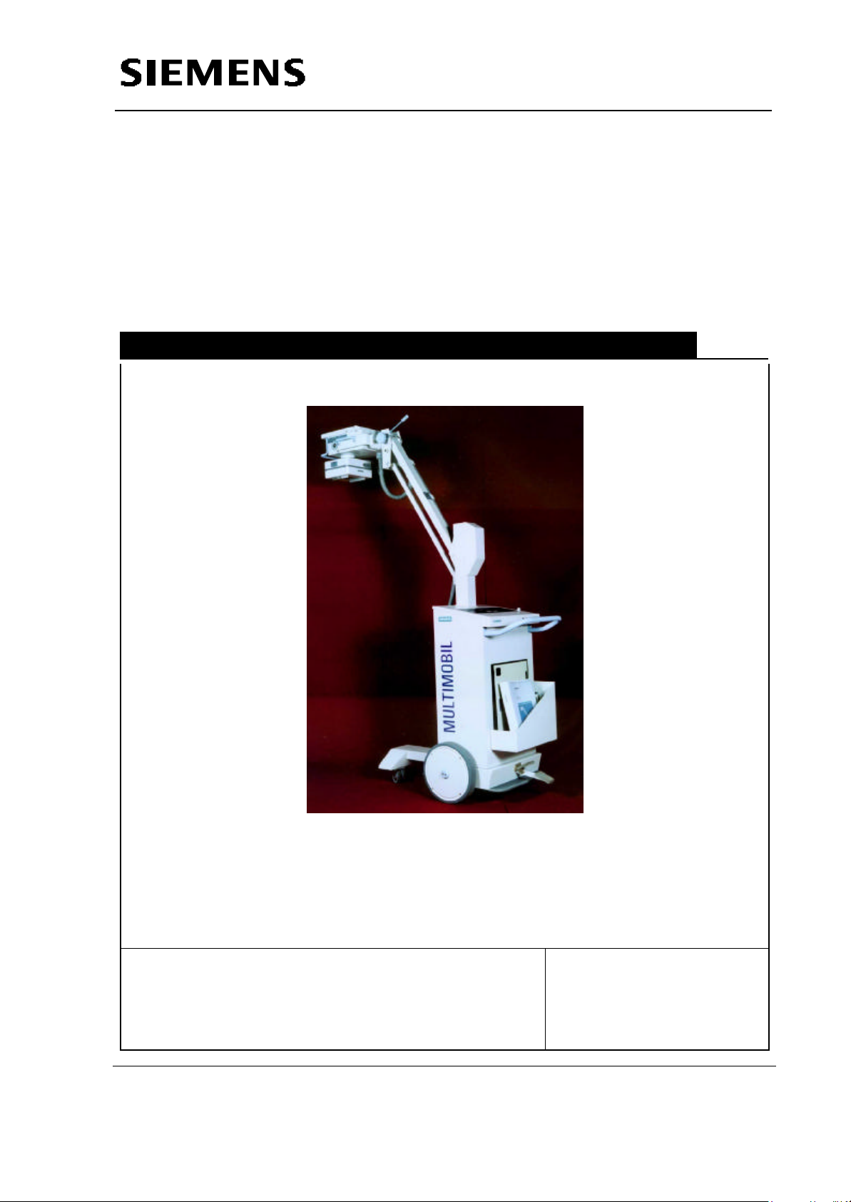
Multimobil 2.5
Service Manual
Maintenance Instructions
Med
Maintenance Instructions
Version: 6.0
Copyright SIEMENS LTD.,MED INDIA
Siemens Ltd. Med India Version 6.0
Copyright SIEMENS LTD. All rights reserved. For internal use only
The reproduction, transmission or use of
this document or its contents is not
permitted without express written
authority. Offenders will be liable for
damages.
8-1
Page 3

Service Manual
Maintenance Instructions
INDEX
8 MAINTENANCE INSTRUCTIONS.......................................................................................8-3
8.1 GENERAL.......................................................................................................................8-3
8.2 REPLACING DAMAGED OR MISSING SCREWS............................................................................8-3
8.3 CLEANING......................................................................................................................8-3
8.4 PRODUCT DISPOSAL .........................................................................................................8-4
8.4.1 Radioprotection Material.............................................................................................8-4
8.4.2 Transformer Oil .........................................................................................................8-4
8.4.3 Plastics....................................................................................................................8-4
8.4.4 Electrolytic Capacitors...............................................................................................8-4
8.5 MECHANICAL RISK...........................................................................................................8-4
8.6 SAFETY CHECKS.............................................................................................................8-5
8.6.1 Daily checks.............................................................................................................8-5
8.6.2 Monthly checks.........................................................................................................8-5
8.7 PERFORMANCE CHECK (EVERY SIX MONTHS).........................................................................8-5
8.8 ALIGNING THE LIGHT FIELD TO THE RADIATION FIELD..................................................................8-6
8.8.1 Operating Sequence..................................................................................................8-6
8.8.2 Adjustment and Evaluation.........................................................................................8-6
8.9 CHECKING AND READJUSTING THE COUNTERWEIGHT..................................................................8-7
8.9.1 Movements...............................................................................................................8-7
8.9.2 Adjustment Instructions.............................................................................................8-7
8.10 REMOVING THE TOP PANEL , FRONT COVER AND X-RAY SOURCE ASSEMBLY ..................................8-8
8.10.1 Removing the top panel .........................................................................................8-8
8.10.2 Removing the Front cover. .....................................................................................8-9
8.10.3 Removing the X-ray source assembly. ....................................................................8-9
8.11 REPLACING THE SINGLE TANK............................................................................................ 8-10
8.12 REPLACING THE COLLIMATOR............................................................................................ 8-10
8.13 REPLACING THE COLLIMATOR LAMP.................................................................................... 8-11
Siemens Ltd. Med India Version 6.0
Copyright SIEMENS LTD. All rights reserved. For internal use only
8-2
Page 4
Service Manual
Maintenance Instructions
8 Maintenance Instructions
8.1 General
All parts, modules of this product must be tested, inspected, for performance and
safety aspects every 12 months to ensure that the product functions properly and is
safe for patients, operating personnal and other persons.
Every 12 months, trained technical personnel should inspect and if necessary replace
system components of the generator which may produce hazardous conditions due to
excessive wear and tear. These instructions should be included in the annual
maintenance performed by Siemens Customer Service.
If more frequent inspections and maintenance are required by federal or local
regulations, ensure compliance with them.
8.2 Replacing damaged or missing screws
Before working on the open MULTIMOBIL 2.5 switch off the unit with the power switch
on the control panel and unplug the power cable.
Before inserting or removing PC boards, observe the ESD regulations.
Damaged or missing screws should only be replaced by steel screws having the
specified tensile strength with Nickel Plating (6492) specified in the Surface Finish
Documents.
8.3 Cleaning
The unit must always be switched OFF or disconnected before cleaning.
Use only water or a luke warm mixture of a household cleaner diluted with water to
clean the unit .
Do not use an abrasive or organic solvents or cleaning agents containing solvents
such as gasoline used for cleaning purposes, alcohol or stain remover . Do not spray
water on the unit.
Switch OFF the system prior to cleaning,disinfecting, or
CAUTION
Clean the unit with a damp cloth or cotton pad.
Dampen the cloth or pad with water or lukewarm, diluted commercially available liquid
sterilizing
cleaning solution.
Siemens Ltd. Med India Version 6.0
Copyright SIEMENS LTD. All rights reserved. For internal use only
8-3
Page 5

Service Manual
Maintenance Instructions
Do not use scouring powder, organic solvents (may damage
CAUTION
materials) or solvent based cleaning fluids (benzene, alcohol,
spot remove). As is commonly known,the ingredients in
disinfectants are hazardous to your health. Ensure that room is
well ventilated when using any disinfectant. Follow the
instructions for using disinfectants.
Do not spray the unit.The cleaning fluid must not seep into the
generator. Substituted phenol based or chlorine releasing
disinfectant can weaken materials and are not recommended.
The same restrictions apply to undiluted solutions with a high
alcohol content (e.g. for disinfecting hands). Disinfectant
sprays should generally not be used, the spray can seep into
the system,and safety features can no longer be guaranteed
(possible damage to electrical components, formation of
flammable mixtures of air and the solution vapour).
To disinfect surfaces, we recommend common liquid solutions of aldehyde-based or
ampholytic surfactant -based disinfectant.
8.4 Product Disposal
Legal regulations may contain special prescriptions concerning the disposal of this
product. In order to avoid environmental damage and/or personal injury, please inform
SIEMENS Customer Service if you want to put the unit out of operation and dispose it.
8.4.1 Radioprotection Material
Lead in X-ray tube assembly and in Collimator 1.65 kg.
8.4.2 Transformer Oil
Oil in X-ray tube assembly, approx. 3.2 kg.
8.4.3 Plastics
Epoxy resin on PC boards, PVC of cables approx. 5 kg.
8.4.4 Electrolytic Capacitors
These capacitors must be emptied. Please inform the Siemens Customer Service.
Capacitors approx. 1.5 kg.
Electrolytic Capcitors approx. 5.5 kg.
8.5 Mechanical Risk
The tension in the spring unit must be relieved. Please inform Siemens Customer
service.
Siemens Ltd. Med India Version 6.0
Copyright SIEMENS LTD. All rights reserved. For internal use only
8-4
Page 6

Service Manual
Maintenance Instructions
8.6 Safety Checks
The user shall follow the following safety checks
8.6.1 Daily checks
Check the power cord. Do not use the unit if the power cord is damaged.
Check the exposure indicator and audible signal during exposure.
Check the locking mechanism for the support arm.
Check that the Single tank assembly and the arm system remain in the desired
position.
8.6.2 Monthly checks
Check the lifting and lowering movements of the support arm.
Check function of locking lever and cap screw on the X-ray tube.
Check the legibility of the labels according to those in section Location of Labels.
If any label requires to be replaced, please notify Siemens customer service.
8.7 Performance Check (Every Six months)
Check Counterbalancing of the support arm at each position.
Check the locking mechanism for the support arm.
Check Brake for proper functioning.
Take a sample exposure at 60 kV, 10 mAs.
Check for Radiation indication LED and the Audio indication in form of Buzzer.
Annual Maintenance must be performed as per the
NOTICE
guidelines described in the Maintenance section.
Siemens Ltd. Med India Version 6.0
Copyright SIEMENS LTD. All rights reserved. For internal use only
8-5
Page 7

8.8 Aligning the light field to the radiation field
X1
8.8.1 Operating Sequence
Load a 24 Cm x 30 cm or 10” x12 “ cassette
with film and place it on a table or base.
Using a tape measure, set a vertical SID of
100cm or 40” to the upper edge of the
cassette as shown.
Using slide flaps set a format of 18 cm x 24
cm or 8”x 10”.
Switch on the Collimator Lamp and align the
cassette.
Attach radio-opaque markings to the
cassette. Attach a washer as lateral marking.
Trigger an exposure and develop the film .
Using a waterproof felt pen, write the following
data on the developed film
- set SID
-film size
-radiation field size
Service Manual
Maintenance Instructions
8.8.2 Adjustment and Evaluation
Measure the deviations between light field
edges and radiation field edges on all four sides
(X1,X2,Y1,Y2) as shown.
Determine the total deviations in the X and Y
direction ( ignore the +/- signs).
Both, length deviation (ΣY) and width deviation
(ΣX) must be ≤ 2.0 cm.
If the deviation is higher, loosen the 4 screws.
slightly and move the collimator accordingly as
shown. Then tighten the screws at the collimator
again.
Repeat the check and, if necessary, adjust the
collimator again until the deviation between the
light field and the radiation field is within the
tolerance (≤ 2 cm).
Siemens Ltd. Med India Version 6.0
Copyright SIEMENS LTD. All rights reserved. For internal use only
8-6
Page 8

Service Manual
Maintenance Instructions
The Adjustment can also be achieved with
the help of a fluoroscent screen.
8.9 Checking and readjusting the counterweight
Unlock the support arm and release the turning knob. Without any accessories
attached, the support arm should be easy to move across the entire movement range
and stop in any position. If the arm is not counterbalancing itself adjustments in the
spring tension are required.
8.9.1 Movements
Check arm counterbalancing at all positions.
It should be easy to lift the arm UP or pull it down.
When the single tank does not remain at the required position, tighten the M10 nut on
the bracket. If it still does not remain at the required position the spring tension should
be adjusted for complete balancing. i.e. If the Single Tank moves DOWN from the
required position, the spring tension is to be increased. If it moves UP, then the spring
tension is to be reduced. Refer adjustment instructions.
8.9.2 Adjustment Instructions
Adjusting the balancing of the arm
Carry out the change in the pre-tension of the spring tension
as explained below.
Remove the column cap from the column.
Fully release the supplementary brake on the support arm.
Move the support arm into the horizontal position. Release
the M10 locknut using two 16/17 open end spanners.
If the Single Tank moves DOWN from the required position,
firmly tighten the M10 nut shown in the picture 16/17 openended spanner. Set the spring tension so that the state of
equilibrium is obtained when the support arm is in the
horizontal position, i.e. that the raising and lowering forces
of the tube assembly are the same. If it moves UP, loosen
the M10 nut. Check the balancing and then tighten the
locknut.
Siemens Ltd. Med India Version 6.0
Copyright SIEMENS LTD. All rights reserved. For internal use only
8-7
Page 9

Service Manual
Maintenance Instructions
8.9.2.1 Adjusting the friction in the arm
1
2
Turn the clamping knob (1) to loosen the friction in the arm system. After adjusting the
position of the arm the clamping knob should be tightened.
Tighten the nut (2) shown periodically using 16/17 Spanner.
In case of balancing problem contact Siemens Customer Service.
8.10 Removing the top panel , front cover and X-ray source assembly
8.10.1 Removing the top panel
Turn off the Multimobil 2.5,disconnect the mains chord and wind the cord around the
cable holder.
Lower the X-ray source assembly to transport position. Lock the Multimobil 2.5 by
applying the brake.
Unscrew the two ornamental screws with 2.5 mm allen key.
Grasp the top panel and lift it (as shown in figure).
Siemens Ltd. Med India Version 6.0
Copyright SIEMENS LTD. All rights reserved. For internal use only
8-8
Page 10

8.10.2 Removing the Front cover.
Turn off the Multimobil 2.5,disconnect the mains chord
and wind the cord around the cable holder.
Lower the X-ray source assembly to transport position.
Lock the Multimobil 2.5 by applying the brake.
Arrange some kind of soft bedding to place the front
cover on .
Unscrew the four ornamental screws with 2.5mm allen
key.
Grasp the cassette box and slowly pull it outside.
Position the front cover on a soft bedding.
Service Manual
Maintenance Instructions
8.10.3 Removing the X-ray source assembly.
Turn off the Multimobil 2.5,disconnect the mains chord and wind the cord around the
cable holder.
Lower the X-ray source assembly to transport position. Lock the movement of the
Multimobil 2.5 by applying the foot brake.
Siemens Ltd. Med India Version 6.0
Copyright SIEMENS LTD. All rights reserved. For internal use only
8-9
Page 11

Service Manual
Maintenance Instructions
Make sure that the X-ray source assembly is properly secured with the transport safety
lock. It should not be possible to move the X-ray source assembly upwards.This is
very important for safety reasons.
Tighten the clamping knob.
Rotate the X-ray source assembly so that the collimator points towards the floor.
Loosen the two hexagonal head bolts with a 16-17 open end spanner three to four
turns for each screw.
Loosen the two screws (two to three turns) mounted on the mounting plate- outer
assembly.
Grab the handles and remove the X-ray source assembly. Place it on a soft bedding
with collimator facing upwards.
Do not attach anything other than the X-ray source
WARNING
assembly to the arm system.
Other objects will disengage the transport safety lock,
causing the arm system to move unanticipated which
can cause both personal injury and damage to the
equipment.
8.11 Replacing the single tank
To replace the single tank, remove it from the mobile stand as follows:
Move the arm system in the lowest (parking) position and check if the safety locking
has engaged.
The arm cannot be moved upwards any longer.
Tighten the supplementry lock turning the knob.
Remove the single tank cover.
Disconnect the Single Tank connections from Control by removing snap-on
connections and the earth connection.
Loosen the two M10 Hex bolts on the mounting plate assembly using 16/17 spanner.
Lift the single tank off vertically and place it on a a soft base.
Detach the collimator
Install the new single tank in the reverse order mentioned above.
Check alignment of light field to radiation field and adjust if necessary .
The parameter adjustments and the calibration of the Unit is
CAUTION
Specific to the Single Tank. In case if the Single Tank is
replaced it is necessary to recalibrate the equipment.
8.12 Replacing the collimator
In case of any damage to collimator housing, the collimator has to be replaced
completely.
Proceed as described in the following
Loosen the allied connector on the collimator cable and disconnect it.
Remove the collimator after loosening the four screws .
Siemens Ltd. Med India Version 6.0
8-10
Copyright SIEMENS LTD. All rights reserved. For internal use only
Page 12

Service Manual
Maintenance Instructions
Attach the new collimator, fasten it with the four screws & follow the light field and
radiation field alignment procedure.
Connect the connecting cable.
Check coincidence of light and radiation field and make adjustment if required
8.13 Replacing the Collimator lamp
Loosen the screw of the clamp which has
marked for light indication on the collimator.
take out the defective lamp and replace it by a
new lamp.
Do not touch the glass envelope with your
CAUTION
bare fingers.
Screw down the bracket and the front panel.Check the function of the lamp.
Siemens Ltd. Med India Version 6.0
Copyright SIEMENS LTD. All rights reserved. For internal use only
8-11
 Loading...