

Page 1

MULTIMOBIL 10
Troubleshooting Guide
SP
© Siemens AG 2003
The reproduction, transmission or
use of this document or its contents
is not permitted without express
written authority. Offenders will be
liable for damages. All rights,
including rights created by patent
grant or registration of a utility
model _or_ design,_are_ reserved.
English
Print No.: SPR8-X01.840.10.02.02 Doc. Gen. Date: 10.05
Replaces: SPR8-X01.840.10.01.02
Page 2
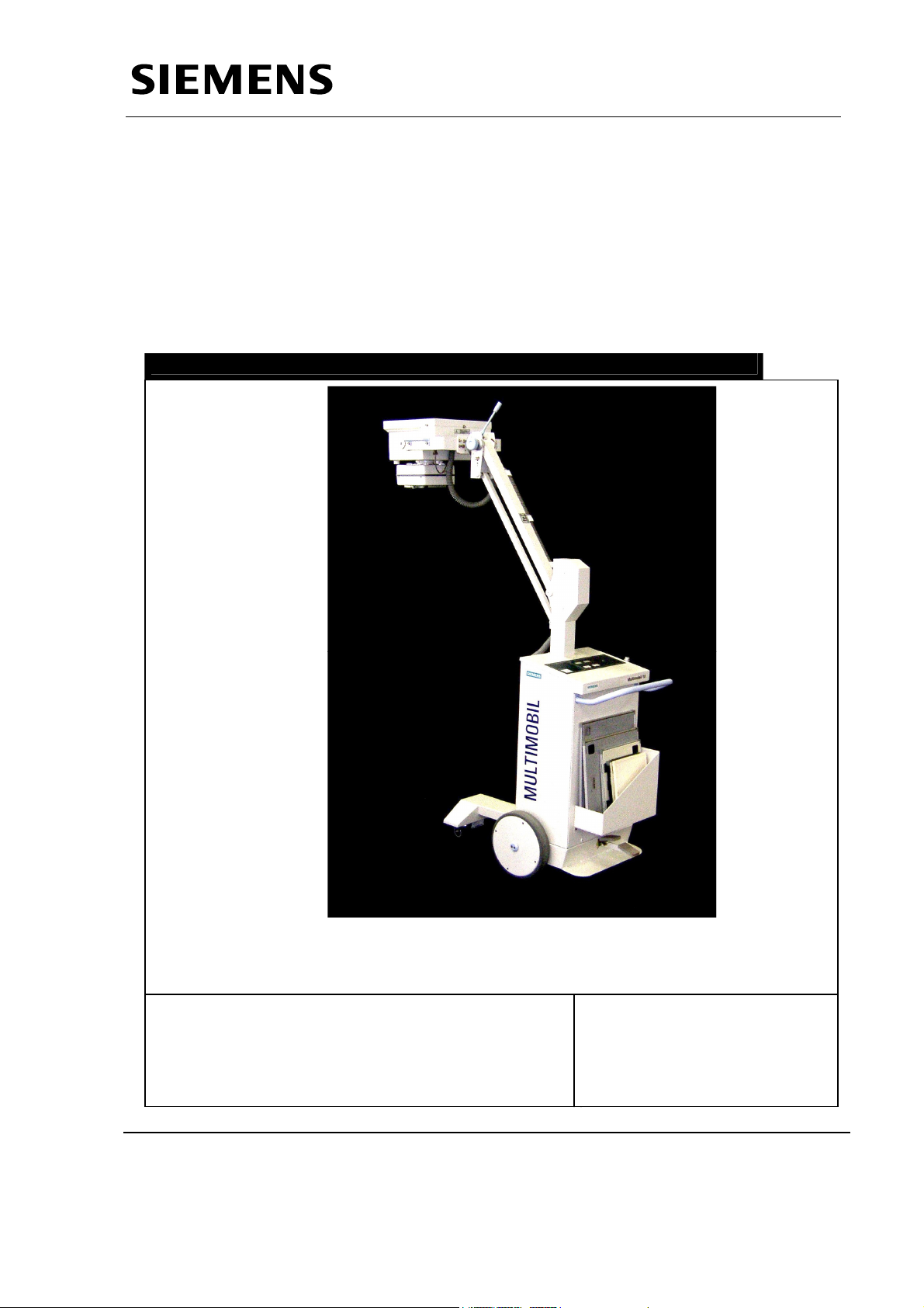
Multimobil 10
Service Manual
Service Instructions
Med
Service Instructions
Version: 4.0
The reproduction, transmission or use
of this document or its contents is not
permitted without express written
authority. Offenders will be liable for
damages.
Siemens Ltd. Med Division India Version 4.0
Page 1 of 48
Page 3

Service Manual
Service Instructions
INDEX
1 SERVICE................................................................................................................................................... 4
1.1 SAFETY PRECAUTIONS : .......................................................................................................................... 4
1.2 TROUBLESHOOTING : .............................................................................................................................. 4
1.2.1 Tools and measuring instruments required....................................................................................... 4
1.3 MEASURING WITH OSCILLOSCOPE : ......................................................................................................... 4
1.4 HANDLING PRECAUTIONS........................................................................................................................ 4
1.5 CONTROL VOLTAGES .............................................................................................................................. 5
1.6 SIGNALS & LINE VOLTAGE DISPLAY: ...................................................................................................... 5
1.7 HT CHECK : ............................................................................................................................................ 6
1.8 EXPOSURE :............................................................................................................................................. 6
1.9 TIMING :.................................................................................................................................................. 6
1.10 KVP,KVN &KV MEASUREMENT :.......................................................................................................... 6
1.10.1 kVp-meter :................................................................................................................................... 6
1.10.2 Electrical :.................................................................................................................................... 7
1.11 MA/MAS MEASUREMENT :...................................................................................................................... 7
1.11.1 mAs-meter : .................................................................................................................................. 7
1.11.2 Electrical :.................................................................................................................................... 7
1.12 CALIBRATION :........................................................................................................................................ 7
1.13 FORMING :............................................................................................................................................... 8
1.14 SAFETY NOTES AND PROTECTIVE MEASURES .......................................................................................... 8
1.15 REPLACING DAMAGED OR MISSING SCREWS ............................................................................................ 8
1.16 CLEANING............................................................................................................................................... 8
1.17 CLEANING THE UNIT............................................................................................................................... 8
1.18 DISINFECTING ......................................................................................................................................... 9
1.19 MAINTENANCE........................................................................................................................................ 9
1.20 PRODUCT DISPOSAL................................................................................................................................9
1.21 SAFETY CHECKS ................................................................................................................................... 10
1.21.1 Daily checks................................................................................................................................ 10
1.21.2 Monthly checks ........................................................................................................................... 10
1.21.3 Performance Check (Every Six months) ..................................................................................... 10
1.22 PROGRAM MODES FOR SERVICING........................................................................................................ 11
1.22.1 Program 1 : To display the DC voltage on the capacitor........................................................... 11
1.22.2 Program 2 : To check the total number of exposures taken . .................................................... 11
1.22.3 Program 3 : To check the type of codes that occurred in the unit maximum 20 ....................... 11
1.22.4 Program 4 : To Erase the errors that have occurred on the unit. .............................................. 12
1.22.5 Program 5 : To set the display value at switch ON to Default Kv mAs combination or last
selected Kv mAs combination. ....................................................................................................................... 12
1.22.6 Program 6 : To set the maximum kV and mAs value for the unit. .............................................. 12
1.22.7 Program 7 : To set the max.inverter firing frequency(REG)...................................................... 12
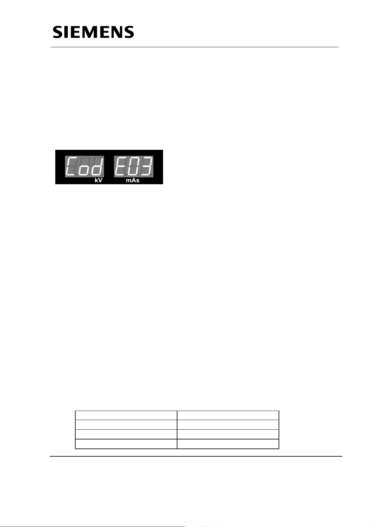
2 CODES..................................................................................................................................................... 14
3
TROUBLESHOOTING ......................................................................................................................... 16
3.1 REMOVING THE TOP PANEL, FRONT COVER AND X-RAY SOURCE ASSEMBLY ......................................... 16
3.1.1 Removing the top panel ................................................................................................................... 16
3.1.2 Removing the Front cover. .............................................................................................................. 17
3.1.3 Removing the X-ray source assembly..............................................................................................17
3.2 CHECKING THE LINE VOLTAGE, FUSES AND LEDS................................................................................. 18
Siemens Ltd. Med Division India Version 4.0
Page 2 of 48
Page 4

Service Manual
3.2.1 Checking the line voltage ................................................................................................................ 18
3.2.2 Checking the fuses........................................................................................................................... 19
3.2.3 Checking the LEDs on D801 ........................................................................................................... 19
3.3 CHECKING THE CONTROL VOLTAGES ................................................................................................... 19
3.4 CHECKING THE INTERMEDIATE CIRCUIT VOLTAGE................................................................................ 20
3.5 CHECKING THE MAXIMUM MAIN INVERTER FREQUENCY ...................................................................... 20
3.6 FILAMENT CURRENT MEASUREMENT .................................................................................................... 20
3.7 CHECKING THE HIGH VOLTAGE KVSOLL AND KVIST............................................................................. 20
3.8 SETTING THE MAXIMUM FILAMENT FREQUENCY .................................................................................. 21
3.9 CHECKING THE TUBE CURRENT ............................................................................................................. 21
3.10 CHECKING THE KV AND TUBE CURRENT (JR)........................................................................................ 21
3.11 CHECKING THE MAS VALUES ................................................................................................................ 21
3.12 ADJUSTING THE MAS ............................................................................................................................ 22
3.13 SWITCHING THE COLLIMATOR LIGHT ON............................................................................................. 22
3.14 ALIGNING THE LIGHT FIELD TO THE RADIATION FIELD .......................................................................... 22
3.14.1 Operating sequence .................................................................................................................... 22
3.14.2 Evaluation: ................................................................................................................................. 22
3.15 CHECKING AND READJUSTING THE COUNTERWEIGHT ........................................................................... 23
3.16 ADJUSTMENT INSTRUCTIONS : .............................................................................................................. 23
3.17 REPLACING THE SINGLE TANK............................................................................................................... 23
3.18 REPLACING THE COLLIMATOR............................................................................................................... 24
3.19 REPLACING THE COLLIMATOR LAMP .................................................................................................... 24
Service Instructions
4 SPECIFIC CODE HANDLING ............................................................................................................ 25
4.1 UNIT NOT SWITCHING ON ..................................................................................................................... 25
4.2 NO RADIOGRAPHY ................................................................................................................................27
4.3 NO STANDBY ........................................................................................................................................ 29
4.4 INITIALISATION CODES.......................................................................................................................... 30
4.4.1 Code 90 (EPROM CHECKSUM FAILURE)................................................................................... 30
4.4.2 Code 96 (KV SOLL FAILURE) ......................................................................................................30
4.4.3 Code 97 ( mA FAILURE) ................................................................................................................ 30
4.5 STANDBY CODES .................................................................................................................................. 31
4.5.1 Code 02 : +15 V Supply Code......................................................................................................... 31
4.5.2 Code 03 & 04 : Iheiz < Istby & Iheiz > Istby.................................................................................. 32
4.5.3 Code 05 : kVist <> 0....................................................................................................................... 33
4.5.4 Code 06 : JR <> 0........................................................................................................................... 34
4.5.5 Code 33 : Main Inverter Short Circuit............................................................................................ 35
4.6 EXPOSURE CODES ...........................................................................................................................36
4.6.1 Code 11 : Main Inverter Short Circuit............................................................................................ 36
4.6.2 Code 12 : kVist > kVmax................................................................................................................. 37
4.6.3 Code 13 : Iheiz > Imax OR JR > Jrmax......................................................................................... 38
4.6.4 Code 14 : kVist < kVsoll.................................................................................................................. 39
4.6.5 Code 15 : JR < JRS......................................................................................................................... 40
4.6.6 Code 17 : Exposure terminated by Backup Timer........................................................................... 41
4.6.7 Code 18 : Premature termination of Exposure................................................................................ 42
4.6.8 Code 21 : Iheiz > Iheiz maximum.................................................................................................... 43
4.6.9 Code 22 : Maximum Preparation Time........................................................................................... 44
4.6.10 Code 10 : Rotating Anode not OK.............................................................................................. 45
4.6.11 Code 31 : No charging ............................................................................................................... 46
4.6.12 Code 01 : Err signal on D950A active ....................................................................................... 48
Siemens Ltd. Med Division India Version 4.0
Page 3 of 48
Page 5
Service Manual
Service Instructions
1 Service
1.1 Safety Precautions :
Before working on the unit ensure that the Mains is switched OFF.
For completely safe working remove mains plug.
The unit must be OFF before removing or putting back the assemblies.
The protective earthing of subassemblies must not be removed in any case.
1.2 Troubleshooting :
1.2.1 Tools and measuring instruments required
• Usual service tools
• Digital Multimeter:
• 2 channel storage oscilloscope with 2 probes and one current probe.
• mAs meter
• Protective ground wire and leakage current tester: Bender safety tester
• Radiation detector
During Oscilloscope operation the protective ground wire connection
in the power cable must not be interrupted under any circumstances.
For measurements where ground loops that may be present could impair the
measuring result, use the Tek amplifier and the trigger attachment.
1.3 Measuring with oscilloscope :
For normal working, the protective earthing of mains must not be removed.
In case system noise is getting coupled to the scope, use the scope in differential
mode.
To measure high voltage, use DIFFERENTIAL probe isolated from ground.
1.4 Handling precautions
Strictly observe ESD precautions while handling PCBs and ESD sensitive
devices.
After the unit is switched ON, the capacitors C1~C12 on D970A and D971
charge to 355V DC. After switching the unit OFF, it takes about 08 minutes for
capacitors to discharge. The presence of DC voltage is indicated by Green
LED V24 on D950A and also V1 ~ V12 LED’s on D970A / D971.
Siemens Ltd. Med Division India Version 4.0
Page 4 of 48
Page 6
Service Manual
Service Instructions
1.5 Control Voltages
Voltage Measuring Point Range
+5 V D915. X15.4 4.8v to 5.2v
+15 V D915. X15.5 13.5v to 16.5v
-15 V D915. X15.7 -13.5v to -16.5v
Collimator Supply D801 . X6 12V ac to 16V ac
1.6 Signals & Line voltage display:
Signal Measuring Point Range Adjustment
kVsoll D915.TP.KVS
2.0 ± 0.1 V for 60kV
D915.P7
during Exposure
mAsoll D915.TP.JRS
3.2 V ± 0.1 V for 160mA
D915.P6
during Exposure
D915.TP. IH during
1.5V± 0.1V
Standby
IH
REG: Max
Main Inv. req.
CAL :Max
Fil.Inv. Freq
D915.TP. IH during
Preparation
D915.TP.REG point
during exposure
D915 TP CAL during
start up
2V ±0.3V (for critically
damped mA)
15 kHz ± 0.5 kHz
15KHz ± 0.5 kHz
D915.P5
D915.P4
D915 .P3
The actual mains Line voltage, at 110 and 230 V supply, is being monitored for
display on the 7 segment display during first step of hand release switch for
radiography. Ensure that display value mathes with actual line voltage with allowed
tolerance ± 5 %. Using P1 potetiometer on D801 PCB, set the voltage accordingly.
This is applicalbe while replacing D915 and D801 PCB also.
If the Line voltage is less than 205 volts on on 230 V line, microcontroller switches
“ON“ the ’LN’ contactor which will support extra voltage through auto transformer
for rotating anode to run at higher speed. In preperation and exposure mode
contactor retains its position. After 5 second of each termination of radiography Line
voltage is being monitored once again.
When unit is connected to 110 V line LN contactor does not function even though
there is a variation in the supply voltage.
Siemens Ltd. Med Division India Version 4.0
Page 5 of 48
Page 7

Service Manual
Service Instructions
1.7 HT Check :
Presence of High Tension
Observe Safety Precautions.
Use radiation protection
1.8 Exposure :
Switch the generator ON.
Set exposure parameters as 60Kv, 16 mAs.
Pull the recoilable exposure release switch and release an exposure.
The yellow LED on top panel lights up for a short duration equal to exposure time.
Audible indication by a Buzzer from the control and muffled sound from inverter
confirms the working of the inverter.
The LED’s on D915 light in the following sequence:
S27 - STEP 1(half press) : V22
Exposure state : V23
In case of code : V24
Code corresponding to the code is displayed on the seven-segment display.
Sharps knocking sound from inverter indicates inverter short circuit, resulting in
code display on the top panel.
1.9 Timing :
Set 60 kV 16mAs
Release an exposure. The radiation indication LED will light for 100msec ± 5msec.
1.10 KVp,KVn &KV Measurement :
The kVp, KVn & KV measurement can be carried out either by kVp-meter or by
electrical measurement.
1.10.1 kVp-meter :
Switch the unit ON.
Insert the kV sensor into collimator channel and connect the cable to the meter.
Open collimator flaps such that the sensor is well covered by the field.
Set the kVp meter at 12pulse and 55-85kV ranges.
Set exposure parameters as 60kV 20mAs.
Release an exposure. The radiation LED will light up during exposure.
The meter will read 57-63kV.
Repeat with meter setting 77-150kV and exposure parameter setting, as 90kV
20mAs.The meter will read 85.5-94.5 kV.
Siemens Ltd. Med Division India Version 4.0
Page 6 of 48
Page 8

Service Manual
Service Instructions
1.10.2 Electrical :
Connect oscilloscope at D915.TP.kV.
Set the exposure parameters as 60kV 16mAs.
Release an exposure.
The recorded waveform will read 2.9V - 3.1V.
Repeat with 100kV 10mAs.
The recorded waveform will read 5V +/-0.25V.
Lower kV indicates code in kVsoll / kV sensing / kV-regulator OR high mA.
Higher kV indicates code in kVsoll / kV sensing / kV regulator.
1.11 mA/mAs Measurement :
mAs measurement could be carried out either by mAs-meter or by electrical
measurement.
1.11.1 mAs-meter :
Remove mAs link on D800 PCB on the Single tank.
Insert mAs-meter leads in the banana sockets mA+ and mA- on D800.
Set meter at, 200mAs and in the mAs mode.
Set exposure parameters as 60kV 32mAs.
Release an exposure.
The meter will read 31 – 33 mAs.
Repeat for exposure parameters 100kV 40mAs.
The meter will read 39 to 41mAs.
1.11.2 Electrical :
Connect oscilloscope at D915.TP.JR.
Set exposure parameters 60kV 16mAs.
Release an exposure.
The recorded waveform will read 3 – 3. 2V.
The exposure time will be 95 - 105mS.
Lower mA indicates code in mAsoll / mA sensing / mA regulator circuit.
Higher mA indicates code in mAsoll / mA sensing / mA regulator or Low kV.
Incorrect mAs indicate code in timer circuitry.
1.12 Calibration :
It is advisable to re-calibrate the unit in case of undershoot or overshoot observed in
the mA wave shape.
Recalibration is required when the single tank is replaced.
Siemens Ltd. Med Division India Version 4.0
Page 7 of 48
Page 9
Service Manual
Service Instructions
1.13 Forming :
If the unit is being installed after six months from the date of despatch, the
capacitors C1~C12 on D970A/D971 need forming. Refer Installation
instructions for forming procedure.
1.14 Safety notes and protective measures
Refer to the General safety note in Chapter on Installation.
Before working on the open MULTIMOBIL 10, switch off the unit with the power
switch at the control panel, the MCB in off position and remove the Mains cable
from socket.
Before inserting or removing PC boards, switch off the generator and observe the
ESD regulations.
1.15 Replacing damaged or missing screws
Damaged or missing screws should only be replaced by steel screws having the
specified tensile strength with Nickel Plating (6492) specified in the Surface Finish
Documents.
1.16 Cleaning
The unit must always be switched OFF or disconnected before cleaning.
Use only water or a Luke warm mixture of a household cleaner diluted with water to
clean the unit.
Do not use an abrasive or organic solvents or cleaning agents containing solvents
such as gasoline used for cleaning purposes, alcohol or stain remover. Do not spray
water on the unit.
1.17 Cleaning the Unit
Switch OFF the system prior to cleaning, disinfecting or sterilizing.
Clean the stand with a damp cloth or cotton pad.
Dampen the cloth or pad with water or lukewarm, diluted commercially available
liquid cleaning solution.
Note:
Do not use scouring powder; organic solvents (may damage materials) or
solvent based cleaning fluids (benzene, alcohol, spot remove).
Siemens Ltd. Med Division India Version 4.0
Page 8 of 48
Page 10
Service Manual
Service Instructions
Do not spray any fluid on the unit. The cleaning fluid must not seep into the
generator.
1.18 Disinfecting
As is commonly known, the ingredients in disinfectants are hazardous to your
health. Ensure that the room is well ventilated when using any disinfectant. Follow
manufacturer’s instructions for the use of the product.
To disinfect surfaces, we recommend common liquid solutions of aldehyde-based or
ampholytic surfactant -based disinfectant.
Substituted phenol based or chlorine-releasing disinfectant can weaken
materials and are not recommended. The same restrictions apply to undiluted solutions
with a high alcohol content (e.g. for disinfecting hands). Disinfectant sprays should
generally not be used, the spray can seep into the system, and safety features can no
longer be guaranteed (possible damage to electrical components, formation off
flammable mixtures of air and the solution vapor.
1.19 Maintenance
All parts, modules of this product must be tested, inspected, for performance and
safety aspects every 12 months to ensure that the product functions properly and is
safe for patients, operating personnel and other persons.
Every 12 months, trained technical personnel should inspect and if necessary
replace system components of the generator, which may produce hazardous,
conditions due to excessive wear and tear. These instructions should be included in
the annual maintenance performed by Siemens Customer Service.
If more frequent inspections and maintenance are required by federal or local
regulations, ensure compliance with them.
1.20 Product Disposal
Legal regulations may contain special prescriptions concerning the disposal of this
product. In order to avoid environmental damage and/or personal injury, please
inform SIEMENS Customer Service if you want to put the unit out of operation and
dispose it.
Radioprotection Material
Lead in X-ray tube assembly and in Collimator 3 kg.
Siemens Ltd. Med Division India Version 4.0
Page 9 of 48
Page 11

Service Manual
Service Instructions
Transformer Oil
Oil in X-ray tube assembly, approx. 7 kg.
Plastics
Epoxy resin on PC boards, PVC of cables approx. 10 kg.
Electrolytic Capacitors
These capacitors must be emptied. Please inform the Siemens Customer Service.
Capacitors approx. 15 kg
Remaining Electrolytic Capacitors approx. 0.5 kg.
1.21 Safety Checks
The user shall follow the following safety checks:
1.21.1 Daily checks
Check the power cord. Do not use the unit if the power cord is damaged.
Check the exposure indicator and audible signal during exposure.
Check that the Single tank assembly and the arm system remain in the desired
position.
1.21.2 Monthly checks
Check the lifting and lowering movements of the support arm.
Check function of locking lever and cap screw on the X-ray tube
Check the legibility of the labels according to those in section Location of Labels.
If any labels require to be replaced, please notify Siemens customer service.
1.21.3 Performance Check (Every Six months)
Check counterbalancing of the support arm at each position.
Check the locking mechanism for the support arm.
Check brake for proper functioning .
Take a sample exposure at 60 kV, 16 mAs.
Check for Radiation indication LED and the Audio indication in form of Buzzer.
Siemens Ltd. Med Division India Version 4.0
Page 10 of 48
Page 12
Service Manual
Service Instructions
Note : Annual Maintenance must be performed as per the guidelines described in
the Maintenance section.
Notify Siemens Customer Service if you do not have a maintenance contract.
1.22 Program Modes for servicing.
To put the unit into service mode, Short the ST link on the D915 and put ON the
unit.Use the Kv+ and Kv- switches to select the required program from 1 to 7.
To check the parameters in the program,press the DL-serv switch once.
1.22.1 Program 1 : To display the DC voltage on the capacitor.
Select the program one in service mode and the display will read as below
Pr 1
Press the switch DL-serv on the D936 once.
The display will read as below
Cap XXX
XXX corresponds to the DC voltage on the capacitors.
1.22.2 Program 2 : To check the total number of exposures taken .
Select the program two in service mode and the display will read as below
Pr 2
Press the DL-serv switch and enter into the program.The display will be
XXX XXX
XXX corresponds to the total number of exposures taken on the unit.
1.22.3 Program 3 : To check the type of codes that occurred in the unit
maximum 20 .
Select the program three in service mode and the display will read as below
Pr 3
Press the switch DL-serv on the D936 once.The display will read as below.
AA XX
AA displays the serial no of the errors occurred in chronological order.
XX corresponds to the type of code.
Siemens Ltd. Med Division India Version 4.0
Page 11 of 48
Page 13
Service Manual
Service Instructions
Press the kV+ switch to check all the codes stored. Maximum 20 codes can be
stored.
1.22.4 Program 4 : To Erase the errors that have occurred on the unit.
Select the program four in service mode and the display will read as below
Pr 4
Press the switch DL-serv on the D936 once.The display will read as below.
Era Err
To erase the errors keep the mAs + switch pressed till the display reads
0 Err
1.22.5 Program 5 : To set the display value at switch ON to Default Kv mAs
combination or last selected Kv mAs combination.
Select the program five in service mode and the display will read as below
Pr 5
Press the switch DL-serv on the D936 once.The display will read as below.
las Val
The default value can be set by selecting the desired kV, mAs combination.
Last selected combination can be stored by pressing the DL-serv switch twice.
1.22.6 Program 6 : To set the maximum kV and mAs value for the unit.
Select the program six in service mode and the display will read as below
Pr 6
Press the switch DL-serv on the D936 once.The display will read as below.
125 100
Set the required limit for kV and mAs using the kV /mAs increment and decrement
switches.
1.22.7 Program 7 : To set the max.inverter firing frequency(REG).
Select the program seven in service mode and the display will read as below
Pr 7
On activation of this program by pressing the DL-serv switch , the display indicates
Adj F
Siemens Ltd. Med Division India Version 4.0
Page 12 of 48
Page 14

Service Manual
Service Instructions
Press the Radiographic exposure switch and monitor REG on Digital storage
Oscilloscope.
The display indicates
F On
Adjust REG for 15 kHz ±0.5kHz by using P4 on D915 card.
Siemens Ltd. Med Division India Version 4.0
Page 13 of 48
Page 15

Service Instructions
2 Codes
Initialisation Codes
90
EPROM Checksum Failure
96
KVsoll Failure
97
JRS Failure
99 Last Reset by Watchdog
Timer
02
+15V Supply Code
03
Iheiz < Istby
04
Iheiz > Istby The maximum value of Standby current permitted is 3.3 A.
05
KVist <> 0
06
JR <> 0
33
Main Inverter Short Circuit
34
Filament Inverter Short Circuit
07
Rot ≠ 0
08
Braking Failure
01
Err signal on D950A active
31
No Charging
10
No Rotation of Rotating Anode
11
Main Inverter Short Circuit
12
KVist > kVmax
13
Iheiz > Imax OR JR > JRmax
The EPROM Checksum is stored at 7FFEh and 7FFFh as a 16 bit word.
During self Diagnostics the software calculates the checksum of the EPROM
and compares with the stored checksum.
During Self Diagnostics the software outputs 7Fh to the D/A converter (B).
The 2.5V at the output of the D/A converter is Read by the µC through Analog
Port 4. The value read should be greater than 7Ah and less than 86h. (I.e.
between 2.39V and 2.62V)
During Self Diagnostics the software outputs 7Fh to the D/A converter (A).
The 2.5V at the output of the D/A converter is Read by the µC through Analog
Port 3. The value read should be greater than 7Ah and less than 86h. (I.e.
between 2.39V and 2.62V)
The built-in Watchdog timer (WDT) is reset by the software every 25 mSec. If
due to some failure the software doesn’t reset the WDT, the WDT in turn will
reset the µC after 65 mSec
Standby Codes
The +15V supply from SMPS is polled by the µC through Analog port 0. The
+15V supply should be between +12V to +18V.
The Filament Standby current is 3A. Iheiz read by the µC through Analog port
2 should be greater than 2.75A. i.e. 1.35V (Iheiz ratio : 1V = 2A)
kVist is read by the µC through Analog port 7. During Standby the value of
kVist read should be Zero. (kVist ratio : 1 V = 20kV)
JR is read by the µC through Analog port 1. During Standby the value of JR
read should be Zero. (JR ratio : 1 V = 50mA)
If the Main Inverter Driver (Cable) is disconnected this Code gets activated.
Also if IGBT Drivers on D960 Card detects Short Circuit of IGBT’s this Code
gets activated.
This Code gets activated if IGBT Drivers on D801 Card detects Short Circuit
of Filament Inverter IGBT’s
The current flowing through both the windings of motor is monitored
separately. During standby Rotor should be off.RT1, RT2=0.
After exposure is terminated the Unit returns to Standby state and braking of
Rotor is started by allowing a DC current to flow through the KI2.During this
state which is for 8 sec after exp, RT1=0 and RT2=1.
Temperature on the heat sink of D950A exceeds it’s limit or Voltage exceeds
365v across capacitors C1~C12 or IGBT V24 on D950A is short circuit.
Voltage on capacitors C1~ C12 does not increase within 3.5sec of CS picking
up or it is less than 335 V DC
Exposure Codes
Anode Rotation in the Single Tank is not taking place. This Code is displayed
if any one of the RT1and Rt2 signal goes low during preparation.
This Code is displayed, when the drivers of the Main Inverter detect short
circuit.
The PkV and NKV is monitored for Max.68kV separately. If the actual value of
kV is greater than this i.e. if the voltages at J12.8 and J12.10 on D915 cross
4.5V, Code is displayed.
Maximum value of Iheiz above which Code will be displayed is 7 A (3.5V).
Service Manual
Siemens Ltd. Med Division India Version 4.0
Page 14 of 48
Page 16

Service Manual
Maximum value of mAist above which Code is displayed is 180mA.
14
KVist < kVsoll
15
JR < JRS
17
Backup Timer
18
Premature Exposure
Termination
21
I > Iheiz Same as Code 04, but during Exposure.
22
Maximum Preparation Time This Code is displayed if First step is pressed for more than 15 sec.
kVist is continuously polled during exposure. The value of kVist should be
greater than 85% of kVsoll
JR is continuously polled during exposure. The value of JR should be greater
than 50% of JRS.
If regular means of terminating exposure fails and exposure gets terminated
by the backup timer.
Exposure Release Switch is released before the exposure is terminated by
the mAs Integrator.
Service Instructions
Siemens Ltd. Med Division India Version 4.0
Page 15 of 48
Page 17
Service Manual
Service Instructions
3 Troubleshooting
In case of Code, perform the following checks.
3.1 Removing the top panel, front cover and X-ray source assembly
3.1.1 Removing the top panel
Turn off the Multimobil 10,disconnect the mains chord and wind the cord around the
cable holder.
Lower the X-ray source assembly to transport position. Lock the Multimobil 10 by
applying the brake.
Unscrew the two ornamental screws (see location in figure) with 2.5 mm allen key.
Grasp the top panel and lift it (as shown in figure).
Siemens Ltd. Med Division India Version 4.0
Page 16 of 48
Page 18
3.1.2 Removing the Front cover.
Service Manual
Service Instructions
Turn off the Multimobil 10,disconnect the
mains chord and wind the cord around the
cable holder.
Lower the X-ray source assembly to
transport position. Lock the Multimobil 10
by applying the brake.
Arrange some kind of soft bedding to place
the front cover on .
Unscrew the four ornamental screws with
2.5mm allen key.
Grasp the cassette box and slowly pull it
outside.
Place the front cover on a soft bedding.
3.1.3 Removing the X-ray source assembly.
Turn off the Multimobil 10,disconnect the mains chord and wind the cord around the
cable holder.
Lower the X-ray source assembly to transport position. Lock the Multimobil 10 by
applying the brake.
Make sure that the X-ray source assembly is properly secured with the transport
safety lock. It should not be possible to move the X-ray source assembly
upwards.This is very important for safety reasons.
Siemens Ltd. Med Division India Version 4.0
Page 17 of 48
Page 19

Service Manual
Service Instructions
Tighten the clamping knob.
Rotate the X-ray source aassembly so that the collimator points towards the floor.
Loosen the two Socket head Screws with a 8mm allen key three to four turns for
each screw.
Loosen the other four Socket head Screws with a 5mm allen key as shown in the
above figure.
Grab the handles and remove the X-ray source assembly. Place it on a soft bedding
with collimator facing upwards.
Do not attach anything other than the X-ray source
assembly to the arm system.
Other objects will disengage the transport safety
WARNING
lock, causing the arm system to move
unanticipated which can cause both personal injury
and damage to the equipment.
3.2 Checking the line voltage, fuses and LEDs
3.2.1 Checking the line voltage
Measure the supply voltage at site using the digital Multimeter.
Ensure that the supply conditions
• Voltage
• Frequency
are within limits as specified in the Technical Specifications for the Unit.
Switch the Unit ON
Note : If the Unit cannot be switched ON
Check Supply at Mains socket.
Check Continuity of mains cable with the Plug pins.
Check Over Current Protective devices U1 & U2.
Switch the Unit OFF.
Siemens Ltd. Med Division India Version 4.0
Page 18 of 48
Page 20

Service Manual
Service Instructions
3.2.2 Checking the fuses
Open the front cover of the control unit.
Loosen the Fuse carrier, which are mounted on the transformer bracket of the
control unit and check the continuity of fuse link. If fuse link has responded for
overcurrent replace the Fuse Link.
3.2.3 Checking the LEDs on D801
F1 6AT Filament Inverter supply.
F2 1AT SMPS supply
F3 2.5AT Rotating Anode supply .
F4 2.5AT 24V Ac supply for Control ckt.
F5 10AT Collimator supply
F6 0.8 AT DC-DC Conv. ckt.
F7 1.6AT 220V AC supply for contactors.
Standby mode
On D801 the following LED’s are illuminated
V30 Supply for SMPS
V31 Supply for Filament Inverter.
V32 Supply for Rotating Anode ckt
V35 12V AC Supply for Collimator
V36 +VP supply
V50 24V DC on D801
V23&V24 DC supply for filament inverter
3.3 Checking the Control Voltages
In the standby state of the Unit,measure the voltages DC at X15 connector of D915
PCB.
Pin
No.
Signal Name Input/Output max. permissible
voltage/current
1 Dgnd Input 0V
2 -nc- -nc- 3 Dgnd Input 0V
4 DC supply Input + 5V
5 DC supply Input +15V
6 Agnd Input 0V
7 DC supply Input -15V
- nc - = No Connection
Siemens Ltd. Med Division India Version 4.0
Page 19 of 48
Page 21

Service Manual
Service Instructions
3.4 Checking the Intermediate circuit voltage
Measure the voltage on the D970A or D971 PCB across the capacitor using the
digital Multimeter. It should be 355 V dc (+ 10 V / - 5 V dc).
3.5 Checking the maximum main inverter frequency
Turn the Unit OFF.
Place the ST Link on D915 so as to short the two terminals.
Connect oscilloscope on D915.TP.REG and D915.TP.GND.
Turn Unit ON. The unit is now in the Service mode.
In the Service Mode of the unit, select the Prog 7.
On activation of this mode by pressing the DL Service Switch on D936, the
radiographic display indicates
AdJ F
Press the Radiographic Exposure switch and monitor REG on the oscilloscope.
The display indicates
F On
No Radiation.
F max= 15 ± 0.5 kHz.
Adjust the maximum main inverter frequency with potentiometer P4 on D915
Turn the Unit OFF. Remove ST link.
3.6 Filament current measurement
Turn the Unit OFF.
Connect oscilloscope to D915.TP.IH
Turn the Unit ON.
After approx. 3 seconds the Stand-by filament current starts & equal to 1.5V ± 0.2V
Trigger exposure with default values for kV and mAs.
Observe the change in voltage level from 1.5 V ± 0.2V to Preheat value approx.2.0V
Note: Preheat value is parameter (kV & mAs) specific. Just observe the change in
level on preheating step.
3.7 Checking the high voltage kVsoll and kVist
Connect oscilloscope to D915.TP.KVS & D915.TP.KV
Turn the unit ON.
Trigger an exposure with the default values.
Siemens Ltd. Med Division India Version 4.0
Page 20 of 48
Page 22
Service Manual
Service Instructions
Observe the voltage on C.R.O with the scale corresponding to 1V= 30kVfor KVS
and 1V=20KV for KV.
3.8 Setting the Maximum filament frequency
Turn the Unit OFF.
Remove the cable Connector X11 ON D915.
Connect oscilloscope to D915.TP.CAL
Turn the unit ON
The display indicates
Using P3, set the maximum filament frequency on D915 (15 kHz ± 0.5kHz)
Note: Duty Cycle of the waveform is varying as the ON time is fixed.
Connect X11 on D915.
3.9 Checking the tube current
Connect oscilloscope to D915.TP.JRS & D915.TP.JR
Turn the unit ON.
Trigger an exposure with the default values.
Observe the voltage on CRO (1V = 50mA) & confirm value for selected kV & mAs.
3.10 Checking the kV and tube current (JR)
Connect oscilloscope to D915.TP.KV & D915.TP.JR
Turn the unit ON.
Trigger an exposure with the default values.
Observe the voltage on CRO (1V = 50mA & 1V=20kV) for selected kV & mAs .
3.11 Checking the mAs values
Turn the Unit OFF.
Connect mAs meter to “mAs +/ mAs-” on D800 PCB.
Turn the Unit ON.
Trigger the following exposures:
Setting at control panel Valid mAs values
60kV,16mAs
60kV,100mAs
100kV,50mAs
15.5−16.5 mAs
96−104 mAs
48−52 mAs
Siemens Ltd. Med Division India Version 4.0
Page 21 of 48
Page 23

Service Manual
Service Instructions
Turn the Unit OFF.
Remove the mAs meter and reinsert the Link on the D800 PCB.
3.12 Adjusting the mAs
Turn the Unit OFF.
Remove the Shorting Link “mAs +/-” on D800 PCB banana sockets.
Connect mAs meter to “mAs +/ mAs-” on D800 PCB.
Turn the unit ON.
Trigger the exposures for default kV & mAs settings.
Observe the mAs meter reading and if it is not within the tolerance (i.e. 10% for mAs
<20 mAs and 5% for mAs > 20mAs) of set value adjust the potentiometer P1 on
D915 card
3.13 Switching the Collimator Light ON
Switch ON Collimator Lamp. The Halogen lamp will light up and field of light will
appear on the target. The lamp will be switched OFF automatically after 30
seconds.
If the collimator lamp is switched ON and OFF several times within a short
period, overload protection will automatically switch the light OFF. Cool-down
periods are recommended.
3.14 Aligning the light field to the radiation field
3.14.1 Operating sequence
Load a 24 Cm x 30 cm or 10” x12 “ cassette with film and place it on a table or a
similar base. Using a tape measure, set a vertical SID of 100cm or 40” to the upper
edge of the cassette. Using slide flaps set a format of 18 cm x 24 cm or 8”x 10”.
Switch on the Collimator Lamp and align the cassette. Attach radio-opaque
markings to the cassette. Attach a washer as lateral marking. Trigger an exposure
and develop the film .
Using a waterproof felt pen, write the following data on the developed film.
- Set SID, Film size, Radiation field size.
3.14.2 Evaluation:
Measure the deviations between light field edges and radiation field edges on all
four sides (X1, X2, Y1, Y2) as shown.
Determine the total deviations in the X and Y direction (ignore the +/- signs).
Both, length deviation (ΣY) and width deviation (ΣX) must be less than 1.6 cm.
Siemens Ltd. Med Division India Version 4.0
Page 22 of 48
Page 24
Service Manual
Service Instructions
If the deviation is higher, loosen the 4 screws slightly and move the collimator
accordingly. Then, tighten the screws at the collimator again.
Repeat the check and, if necessary, adjust the collimator again until the deviation
between the light field and the radiation field is within the tolerance (< 2 cm).
The adjustment can also be achieved with the help of a fluorescent screen.
3.15 Checking and readjusting the counterweight
Unlock the support arm and release the turning knob. Without any accessories
attached, the support arm should be easy to move across the entire movement
range and stop in any position. If the arm is not counterbalancing itself adjustments
in the spring tension are required.
Movements:
Check arm counterbalancing at all positions.
It should be easy to lift the arm UP or pull it down.
When the single tank does not remain at the required position, the spring tension
should be adjusted for complete balancing. If the Single tank moves DOWN from
the required position, the spring tension is to be increased. If it moves UP, then the
spring tension is to be reduced.
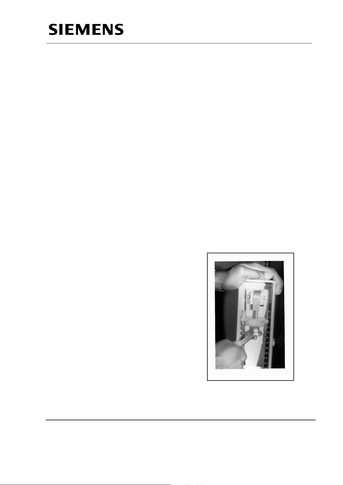
3.16 Adjustment Instructions :
Carry out the change in the pre-tension of
the spring tension as explained below.
Remove the cover from the stand.
Fully release the supplementary brake on
the support arm.
Move the support arm into the horizontal
position.
Firmly tighten the screw using a 17mm
open-ended spanner. Set the spring tension
so that the state of equilibrium is obtained
when the support arm is in the horizontal
position, i.e. that the raising and lowering
forces of the tube assembly are the same.
3.17 Replacing the single tank
To replace the single tank, remove it from the mobile stand as follows:
Move the arm system in the lowest (parking) position and check if the safety
locking has engaged.
The arm cannot be moved upwards any longer.
Siemens Ltd. Med Division India Version 4.0
Page 23 of 48
Page 25
Service Manual
Service Instructions
Tighten the supplementary lock turning the knob.
Detach the collimator from single tank. Also remove the allied connector connected
to the single tank bottom cover.
Remove the handle, single tank bottom cover and the single tank top cover.
Disconnect the Single Tank connections from Control by removing snap-on
connections and the M5 hex nuts of U, V and Gnd.
Remove the 4 nos. socket head screws M6 X 18 using 5mm Allen key. Loosen the
two socket head screws M10 X 35 using the 8mm Allen key.
Lift the single tank off vertically and place it on a soft base.
Install the new single tank in the reverse order.
Check alignment of light field to radiation field and adjust if necessary.
The parameter adjustments and the calibration of the Unit is Specific to the Single
Tank. In case if the Single Tank is replaced it is necessary to recalibrate the
equipment.
3.18 Replacing the collimator
In case of any damage to collimator housing, the collimator has to be replaced
completely.
Proceed as described in the following
Loosen the allied connector on the collimator cable and disconnect it from the single
tank bottom cover.
Remove the collimator after loosening the four screws.
Attach the new collimator, fasten it with the four screws Connect the allied back.
Follow the light field to radiation field alignment procedure as mentioned above.
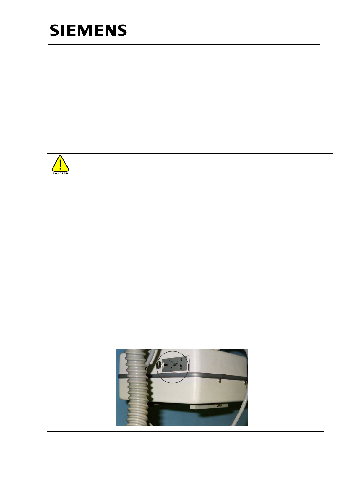
3.19 Replacing the Collimator lamp
Loosen the screw of the clamp, which has marked for light indication on the
collimator. Take out the defective lamp and replace it by a new lamp.
Caution : Do not touch the glass envelope with your bare fingers.
Check functioning of the lamp.
Siemens Ltd. Med Division India Version 4.0
Page 24 of 48
Page 26
Service Manual
Service Instructions
4 Specific Code Handling
Note :Please Ensure that the Calibration of the unit is done properly before
starting with the code Handling.
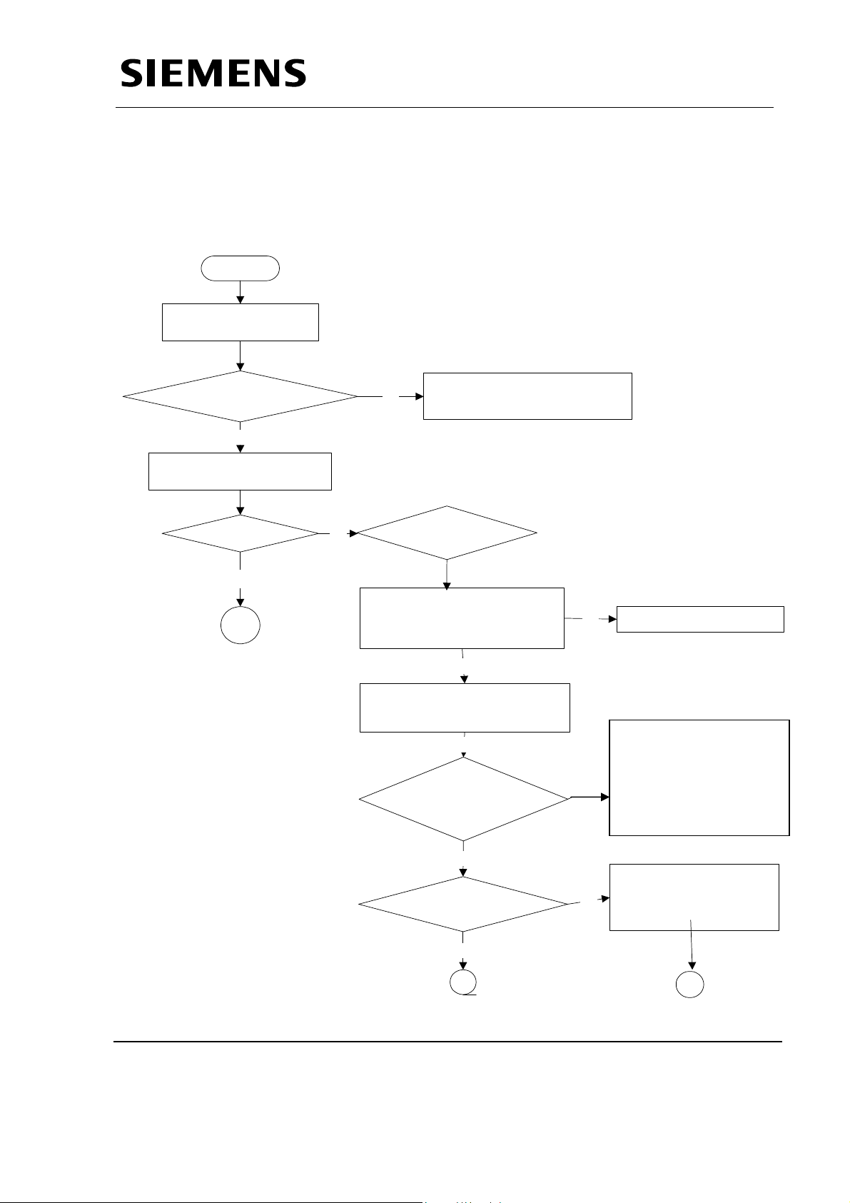
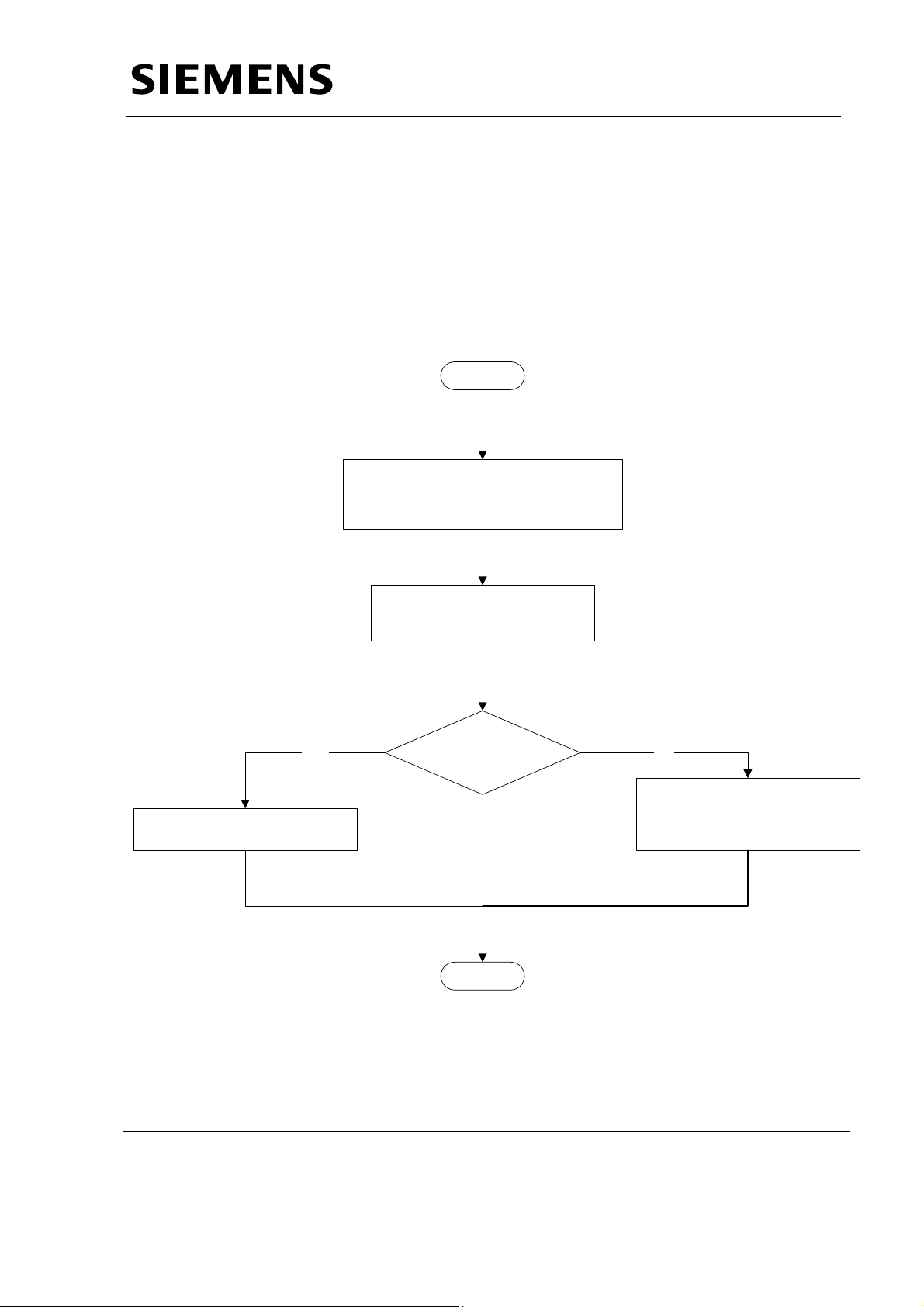
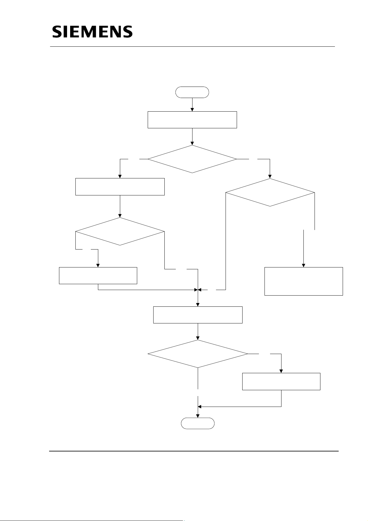
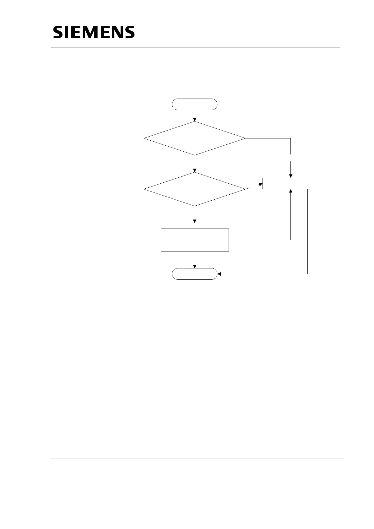
4.1 Unit not switching ON
START
MAKE MAINS
SWITCH ON
LED V50 ON on D801
Yes
PRESS SWITCH I ON
THE TOP PANEL
UNIT ON ?
yes
B
No
No
Are Transformer O/P?
Check Voltages on D801
between terminals X1.6-X1.7
Press the On Switch on the
Relay K5 and then K4 on
CHECK MAINS SUPPLY
should be 24V~.
Yes
Top Panel
Yes
D801 ON
No
No
Replace Transformer
(ON/OFF SWITCH IS
IF (ON/OFF SWITCH IS
Found faulty)
found faulty) THEN
THEN REPLACE D936
REPLACE D936 ELSE
ELSE
REPLACE D801.
REPLACE D801
IF
Yes
Check 220V on
Contactors NS,CS
operates?
Yes
B
No
D801X50.1-X50.3
Ensure relays K4,CS1
are operating.
A
Siemens Ltd. Med Division India Version 4.0
Page 25 of 48
Page 27
Service Manual
Service Instructions
A
Measure voltages at X1.1 and
X1.4 of D801 should be 230v~
StopB
Siemens Ltd. Med Division India Version 4.0
Page 26 of 48
Page 28

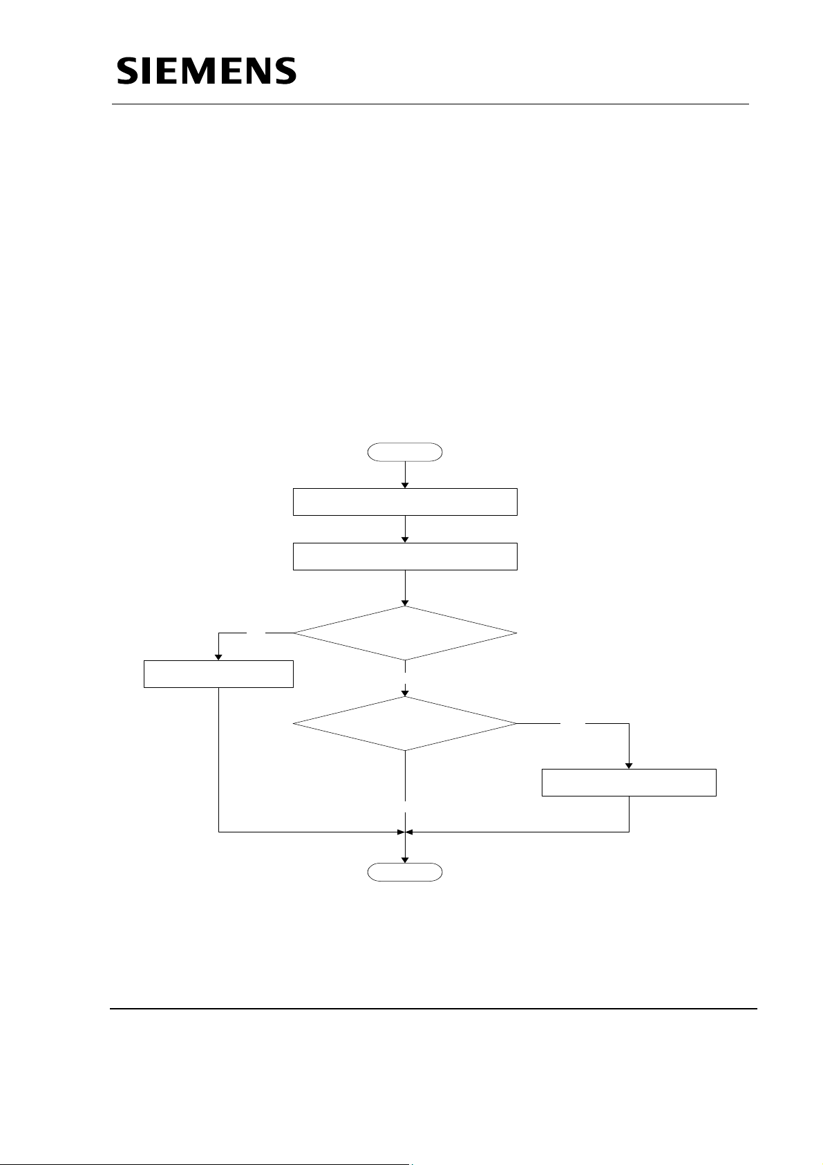
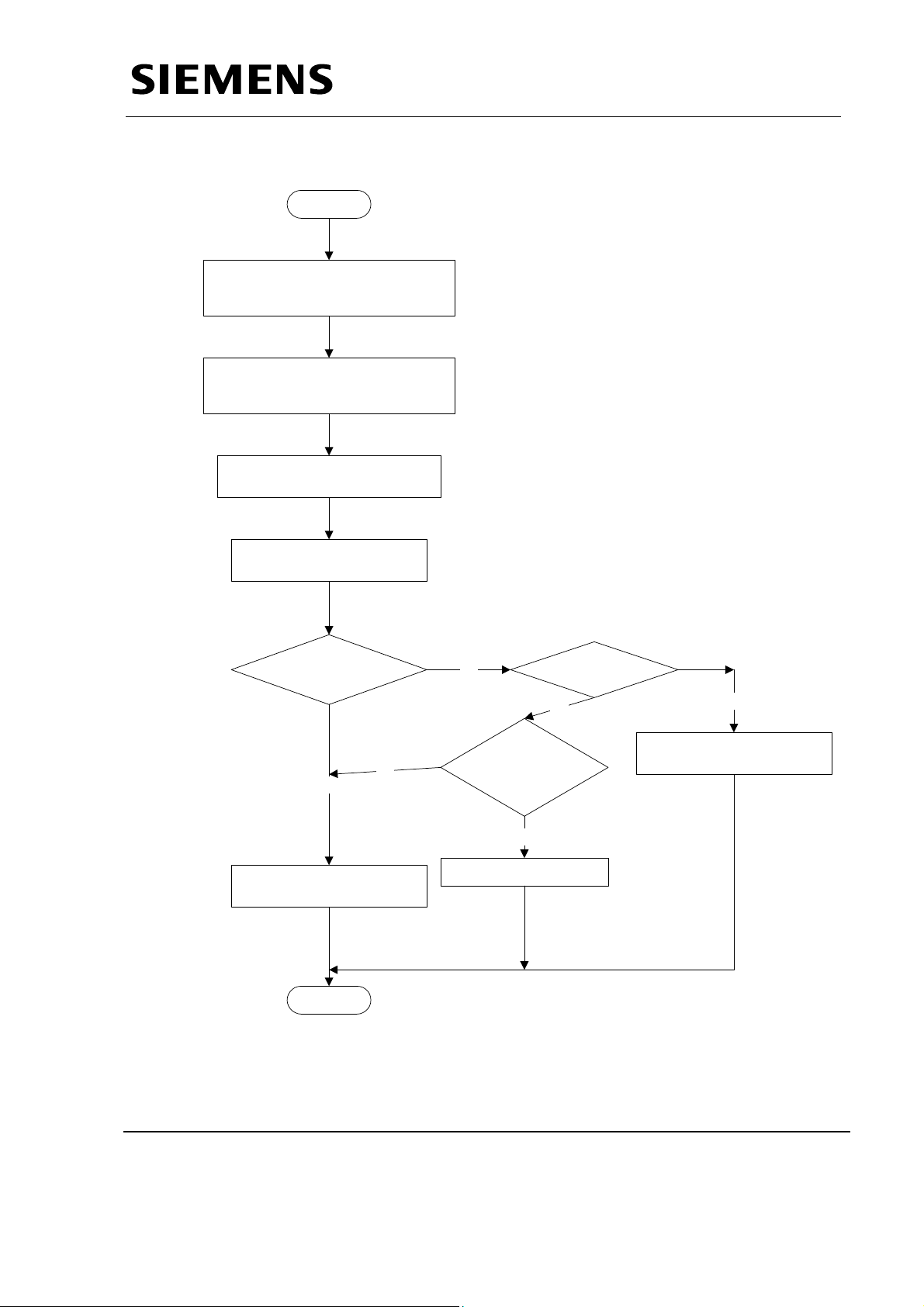
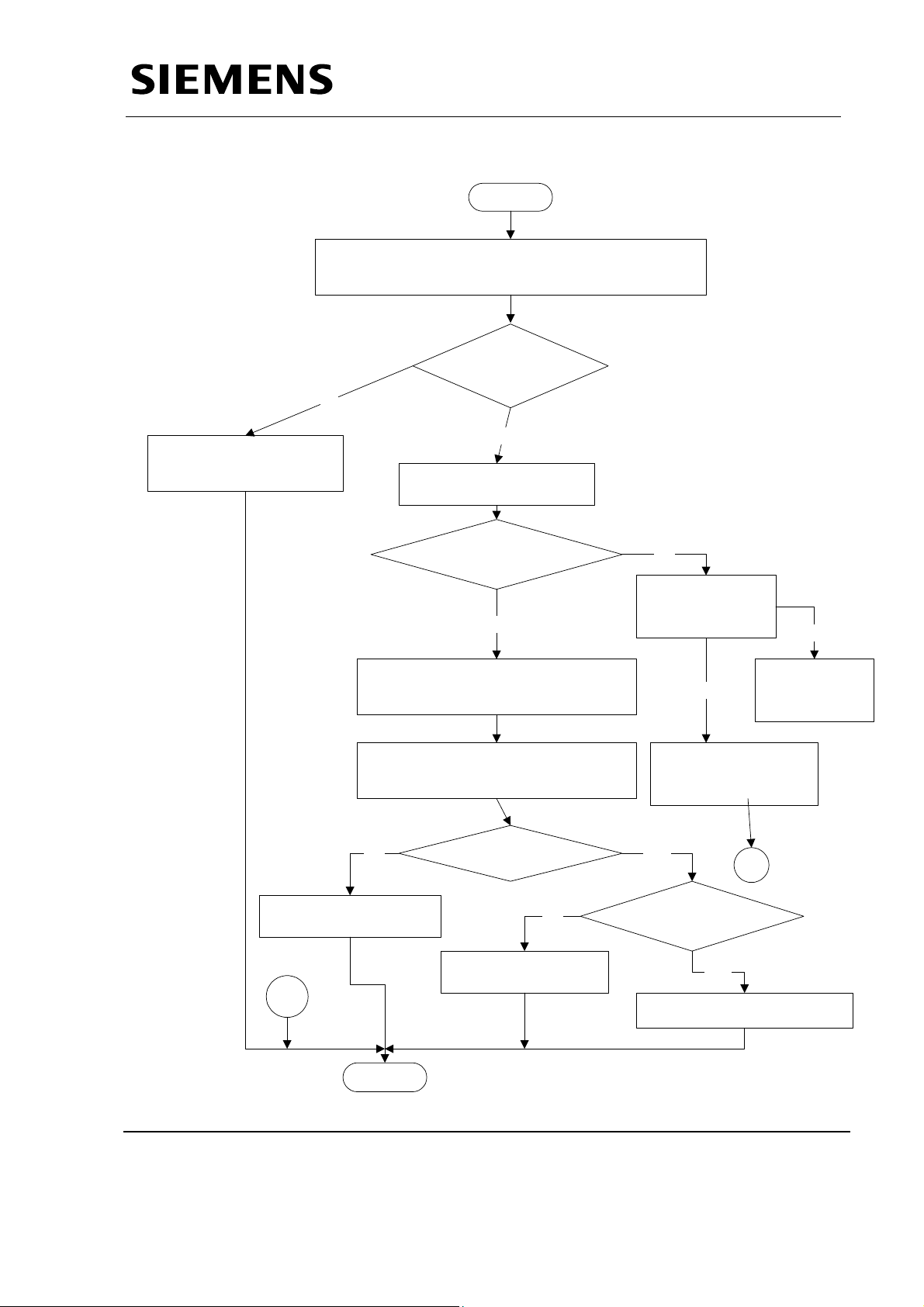
4.2 No Radiography
Service Manual
Service Instructions
START
UNIT IN STANDBY
STATE ?
Yes
PRESS RADIOGRAPHIC FIRST STEP.
FILAMENT BOOSTING ?
Yes
PRESS RADIOGRAPHIC SECOND
STEP.
No
GO TO INITIALISATION
GO TO INITIALISATION
ERRORS
ERRORS PAGE 25
NO
RADIAGRAPHIC
EXPOSURE INITIATED
No
B
?
Yes
EXPOSURE ERROR ?
Yes
GO TO EXPOSURE
GO TO EXPOSURE ERRORS
ERRORS
PAGE 31
NO
A
Siemens Ltd. Med Division India Version 4.0
Page 27 of 48
Page 29
Contd….
B
Service Manual
Service Instructions
HK
SIGNAL ON J36.15 ON
D915 OK ?
Yes
REPLACE D915 PCB
No
+15V SUPPLY TO
RADIOGRAPHIC SWITCH
REPLACE RADIOGRAPHIC
RELEASE SWITCH
A
STOP
Siemens Ltd. Med Division India Version 4.0
Page 28 of 48
Page 30

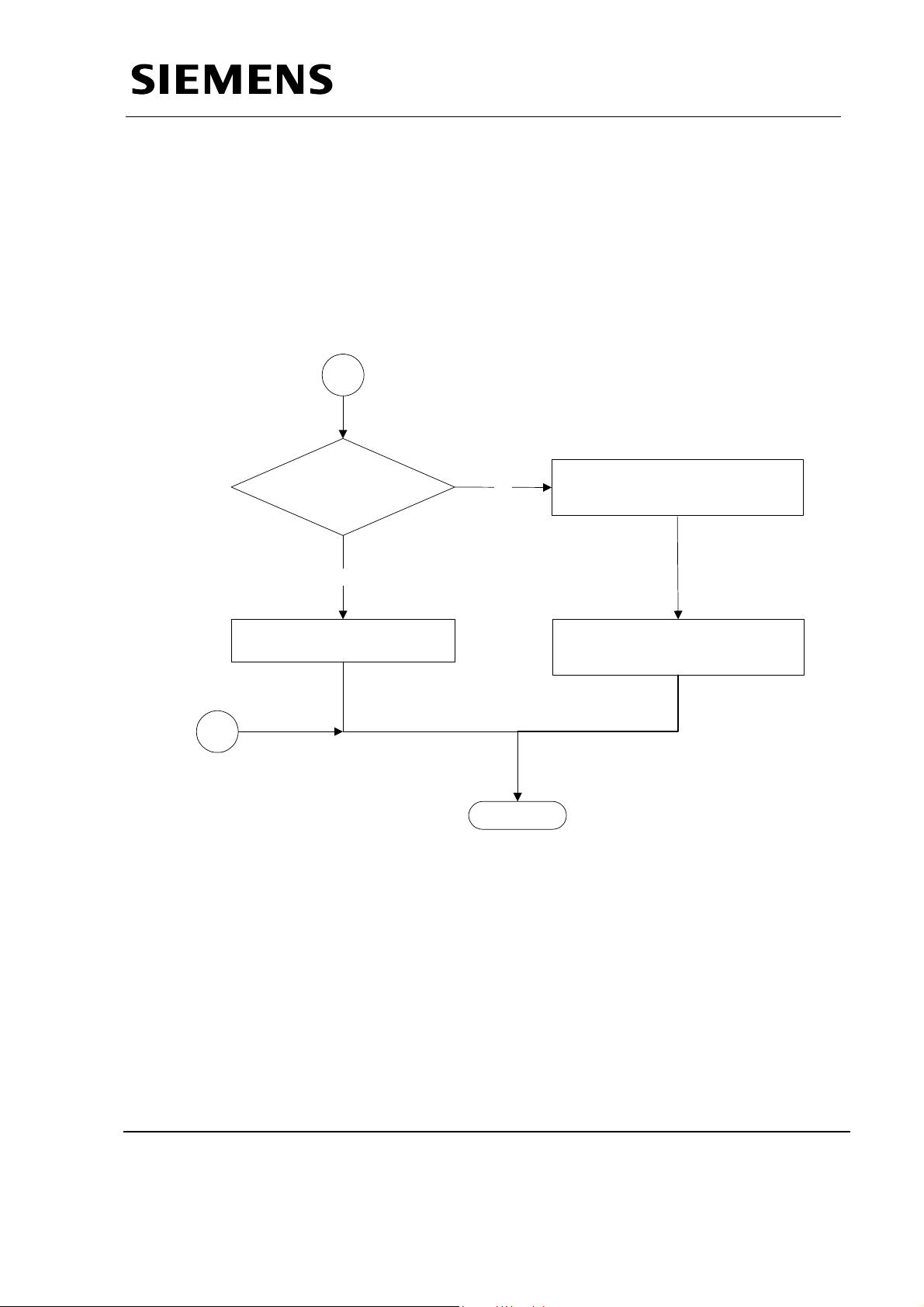
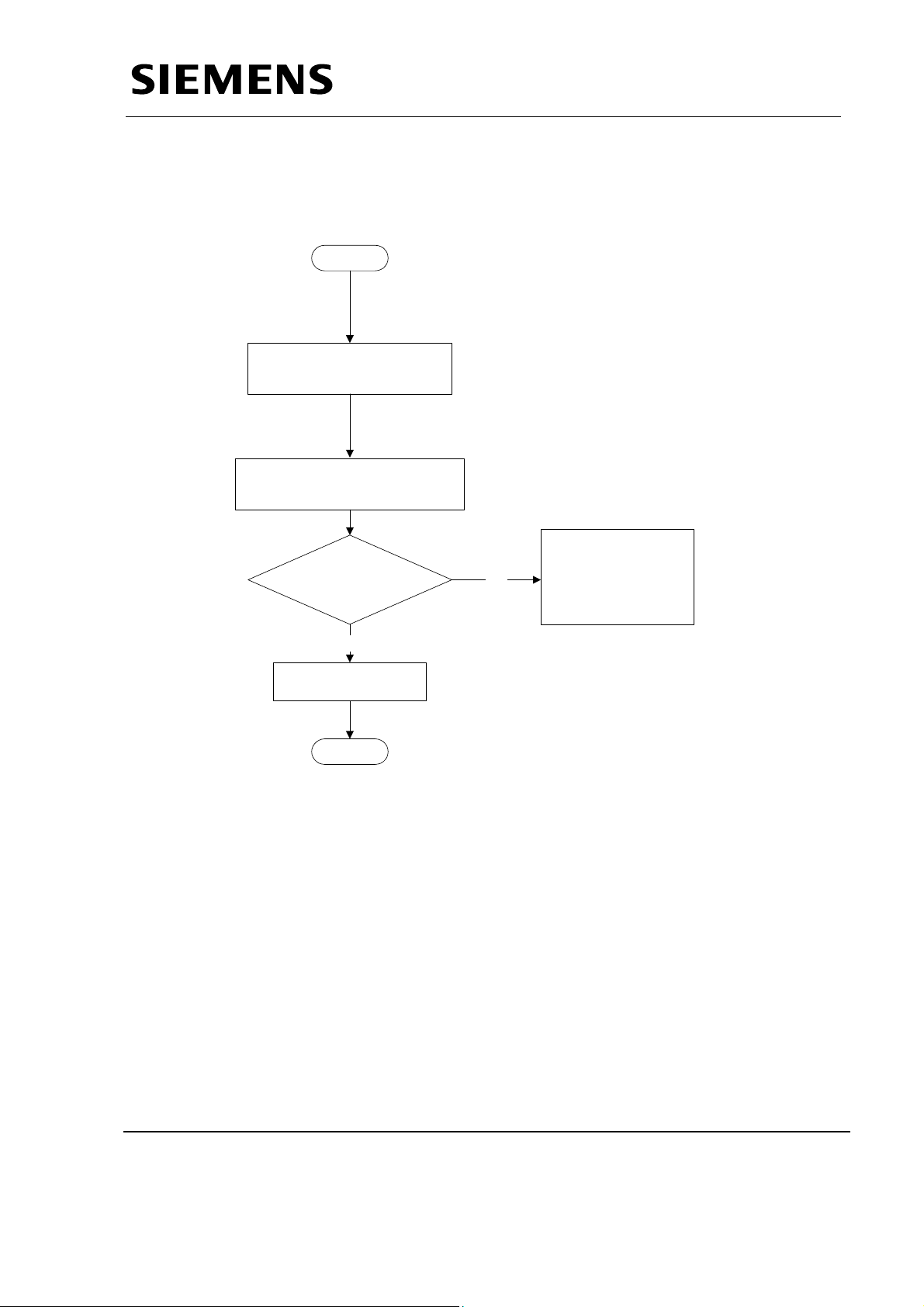
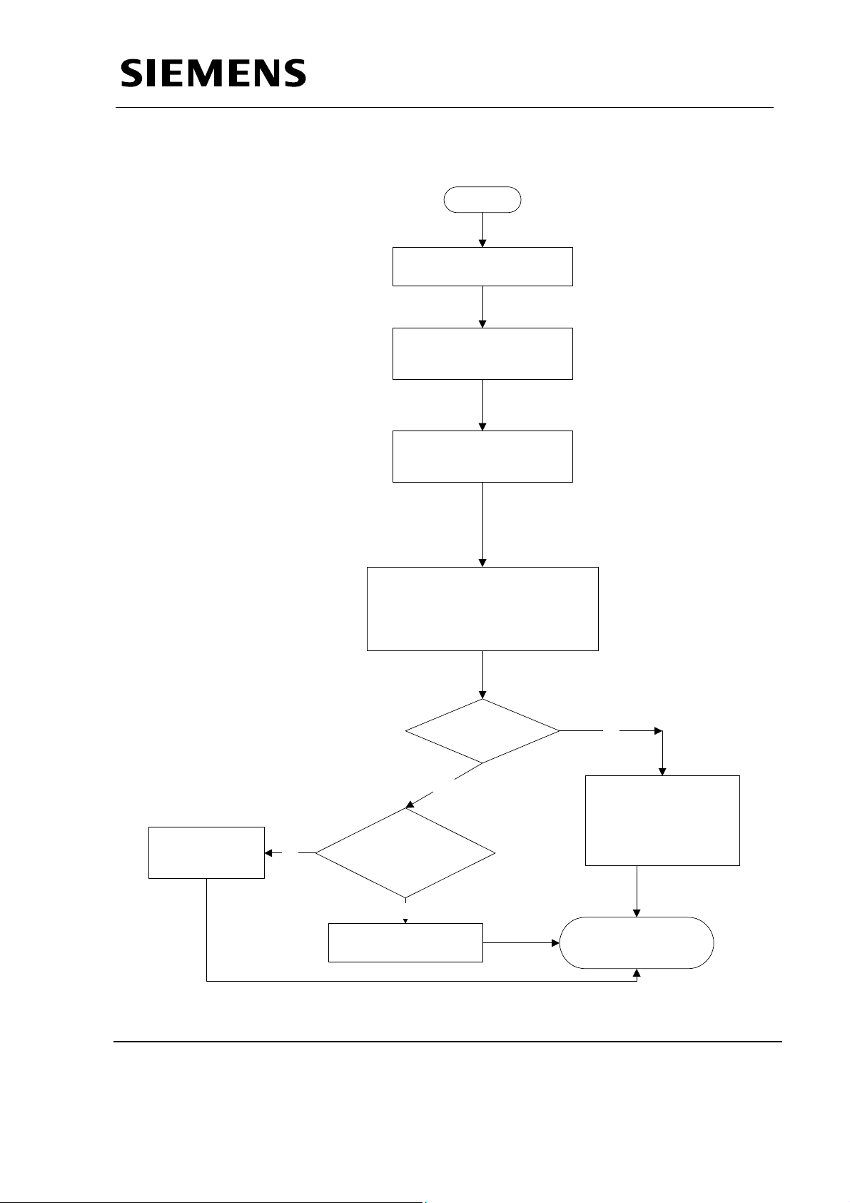
4.3 No Standby
START
MAKE THE MAINS SUPPLY
ON
PRESS the ON SWITCH ON
THE TOP PANEL
UNIT ON
?
Service Manual
GO TO “UNIT NOT
No
GO TO UNIT NOT
SWITCHING ON”
SWITCHING ON PAGE 20.
Service Instructions
Yes
WAIT FOR 3 SEC.
CS contactor
picks up?
Yes
DISPLAYS STABLE
KV,mAS ?
Yes
No
ANY ERROR
?
No
REPLACE D915 AND
CALIBRATE THE UINT
No
GO TO STANDBY ERRORS
GO TO STANDBY ERRORS
PAGE 26
Yes
GO TO INITIALISATION
GO TO “INITIALISATION
ERRORS PAGE 25
ERRORS”
CONFIRM STANDBY
PARAMETERS
STOP
Siemens Ltd. Med Division India Version 4.0
Page 29 of 48
Page 31
4.4 Initialisation codes
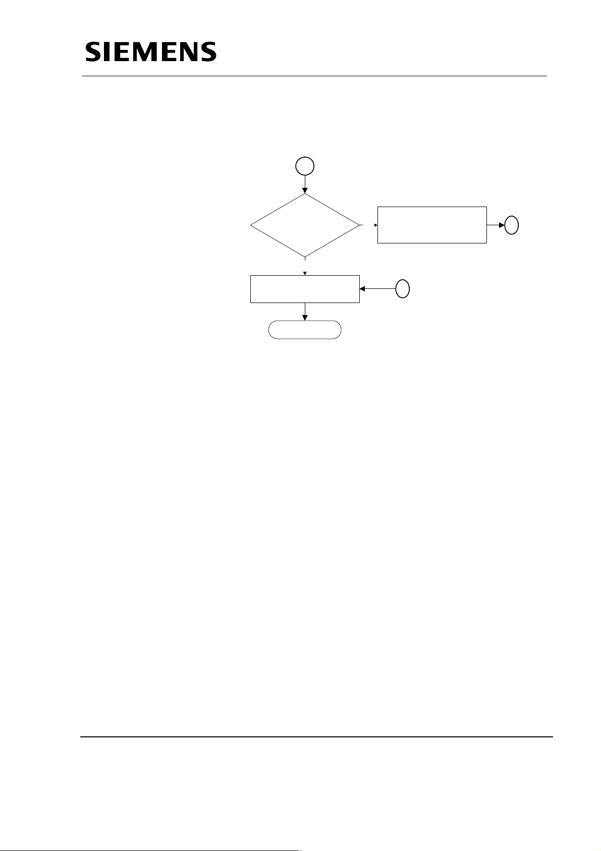
4.4.1 Code 90 (EPROM CHECKSUM FAILURE)
REPLACE J32 FIRMWARE
4.4.2 Code 96 (KV SOLL FAILURE)
ADJUST PRESET P7 ON D915
4.4.3 Code 97 ( mA FAILURE)
ADJUST PRESET P6 ON D915
START
Service Manual
Service Instructions
CONFIRM 230v SUPPLY
SWITCH ON THE UNIT
IS
SUPPLY OK ?
Yes
YES
?
REPLACE D915 PCB
No
STOP
REPLACE D980
NO
X15 CONNECTOR
ERROR CONTINUES
Siemens Ltd. Med Division India Version 4.0
Page 30 of 48
Page 32
4.5 Standby Codes
4.5.1 Code 02 : +15 V Supply Code
REMOVE CONNECOR X15 ON D915
& SWITCH ON THE UNIT
Service Manual
Service Instructions
START
YES
REPLACE D915 PCB
MEASURE +15 V ON X15
CONNECTOR
VOLTAGE=
13.5 TO 16.5 V ?
STOP
NO
ADJUST BY PRESET ON
D980. ELSE
REPLACE D980 PCB
Siemens Ltd. Med Division India Version 4.0
Page 31 of 48
Page 33
4.5.2 Code 03 & 04 : Iheiz < Istby & Iheiz > Istby
START
REMOVE X11 CONNECTOR ON
D915 & SWITCH ON THE UNIT
MONITOR
OBSERVE CAL FOR = 15KHz. &
SWITCH OFF THE UNIT
CAL
FREQUENCY.
TUNE BY P3
Service Manual
Service Instructions
MONITOR I RMS ON D915
I RMS = 0.6V +/- 0.1
No
Yes
REPLACE D915 PCB
STOP
No
Is Filament ON ?
No
Fil pulses at
J22.15 & J22.16 of
D915?
Yes
Replace D801
Yes
ADJUST BY PRESET P5
Siemens Ltd. Med Division India Version 4.0
Page 32 of 48
Page 34

4.5.3 Code 05 : kVist <> 0
START
Service Manual
Service Instructions
KVIST = 0 ?
(NO SPIKES)
Yes
REPLACE D915
No
X8 & X1
(ON D915 & D800) ARE
CONNECTED
PROPERLY ?
SWITCH OFF THE UNIT
R=20 Kohms AT
X8.1,X8.2 & X8.3
YES
Yes
MAKE THEIR
No
NO
REPLACE D800 PCB
ON THE SINGLE
TANK.
PROPER
CONNECTION
STOP
Siemens Ltd. Med Division India Version 4.0
Page 33 of 48
Page 35

4.5.4 Code 06 : JR <> 0
Service Manual
Service Instructions
START
ENSURE ALL CONNECTORS ARE
CONNECTED.
MONITOR JR & SWITCH ON
THE UNIT
REPLACE D915
REPLACE D915
YES
IS
JR = 0 & NO
SPIKES ?
Yes
Yes
STOP
CHECK X8
No
CONNECTOR ON D915.
SWITCH OFF THE UNIT
R=20 OHM AT X8.5 &
X8.6
No
REPLACE D800.
IF THE ERROR CONTINUES,
REPLACE SINGLE TANK AND
CALIBRATE THE UNIT.
Siemens Ltd. Med Division India Version 4.0
Page 34 of 48
Page 36
4.5.5 Code 33 : Main Inverter Short Circuit
START
ENSURE CONNECTIONS OF
X20 CONNECTORS ON
D960 AND D915.
MONITOR VP=15V ON D801.
AND REPLACE D801 IF FOUND
FAULTY.
Service Manual
Service Instructions
ERR/ SIGNAL
OBTAINED FROM D960
IN STBY MODE
No
REPLACE D915
STOP
Yes
CHECK IGBTs AND
REPLACE IF FOUND
SHORTED.
ELSE REPLACE IGBT
MODULE.
Siemens Ltd. Med Division India Version 4.0
Page 35 of 48
Page 37
4.6 EXPOSURE CODES
4.6.1 Code 11 : Main Inverter Short Circuit
START
MONITOR SCM SIGNAL AND
SWITCH ON THE UNIT
ENSURE J34 IC ON
D915 IS WORKING
Service Manual
Service Instructions
IC FAULT ?
No
SWITCH OFF & WAIT
FOR 5 SEC
IGBTS
SHORTED?
Yes
REPLACE IGBTs
ELSE REPLACE IGBT
MODULE
YES
No
REPLACE D915
STOP
Siemens Ltd. Med Division India Version 4.0
Page 36 of 48
Page 38

4.6.2 Code 12 : kVist > kVmax
START
MONITOR KVM & REG SIGNAL AND
TAKE AN EXPOSURE
Service Manual
Service Instructions
KVM PULSE
Yes
IS REG>15KHz ?
Yes
SWITCH OFF THE UNIT AND SHORT
THE
ST
LINK ON D915 PCB
SWITCH ON THE UNIT & SELECT THE
Pr.7 BY PRESSING KV+
PRESS DL_SERV KEY AND THEN
EXPOSURE RELEASE SWITCH
No
YES
ERROR CONTINUES
NO
SWITCH OFF THE UNIT
X8.1,X8.2 W.R.T. X8.3 ON
Yes
REPLACE D915
?
20K AT PIN
IS
D915
PCB ?
NO
A
No
REPLACE D800 PCB
ON SINGLE TANK
MONITOR REG AND SET THE
FREQUENCY TO 15KHz. BY VARYING
POT P4
A
ERROR CONTINUES
?
No
Yes
REPLACE SINGLE
TANK
STOP
Siemens Ltd. Med Division India Version 4.0
Page 37 of 48
Page 39
4.6.3 Code 13 : Iheiz > Imax OR JR > Jrmax
START
MONITOR IH AND JR ON
D915 PCB
IS
YES NO
DECREASE BY VARYING
POT P5 AND P6
IH MAX ERROR
?
Service Manual
Service Instructions
IS JR>JRmax ?
MONITOR I FOR
PULSES
NO
REPLACE D801 PCB
YES
NO
TAKE AN EXPOSURE
ERROR CONTINUES ?
No
YES
REDUCE OVERSHOOTS
IN JR BY PRESET P5
ELSE REPLACE D915
YES
REPLACE D915 PCB
STOP
Siemens Ltd. Med Division India Version 4.0
Page 38 of 48
Page 40
4.6.4 Code 14 : kVist < kVsoll
Service Manual
Service Instructions
START
No
REPLACE D800 PCB ON
SINGLE TANK
SWITCH
COME OUT IN INVERTER MODULE
MONITOR KVIST & KVSOLL AND
OFF
THE UNIT CONFIRM NO WIRE HAS
CONFIRM REG=15+/- 0.2 KHZ
IS
20K AT X8.1,X8.2
w.r.t. X8.3
?
Yes
SWITCH ON THE UNIT
CAP. BANK ON D970A IS
CHARGED ?
Yes
TAKE AN EXPOSURE
NO
CHECK THE O/P
DC VOLTAGE OF
D950A .
Yes
no
REPLACE THE
D950A PCB
MONITOR DISP1 & DISP2
PULSES,TAKE AN EXPOSURE
NO
REPLACE D915 PCB
PULSES ?
NO
U/V CURRENT W/F.
REPLACE THE
CHARGER MODULE
YES
A
OK?
REPLACE IGBT
MODULE
A
YES
REPLACE SINGLE TANK
STOP
Siemens Ltd. Med Division India Version 4.0
Page 39 of 48
Page 41
4.6.5 Code 15 : JR < JRS
Service Manual
Service Instructions
START
SWITCH OFF THE UNIT
CONFIRM mAS LINK ON
D800 PCB
CHECK 'I' FOR 0.6V
+/ -0.1V AC RMS
Check and
replace D800 if
found fauly.
No
Check for 22+/- 3 Ohms between
X8.5 and X8.6 and replace D800 if
found faulty.
KV build up OK?
Yes
Voltage betw. X8.5
and X8.6 is OK?
Yes
Check and replace
D915 if found faulty
No
Check Inverter ckt/
Inverter pulses/
Resonance cap. C5.
STOP
Siemens Ltd. Med Division India Version 4.0
Page 40 of 48
Page 42

4.6.6 Code 17 : Exposure terminated by Backup Timer
START
MONITOR JR ON D915 &
mAS ON D800 PCBS
Service Manual
Service Instructions
YES
MULTIPLY JR & PULSE
DURATION OF J1.9
IS
IT EQUAL TO mAS
?
Yes
ARE PULSES ?
NO
No
ADJUST FREQUENCY AT J1.9 BY
VARYING P1
NO
TAKE AN EXPOSURE AND
NOTE THE TIME
TIME EXCEEDS
EXPOSURE TIME ?
Yes
ERROR CONTINUES
Yes
?
REPLACE D915 PCB
NO
STOP
Siemens Ltd. Med Division India Version 4.0
Page 41 of 48
Page 43
4.6.7 Code 18 : Premature termination of Exposure
START
PRESS KV mAs KEY.
ERROR IS REMOVED.
Service Manual
Service Instructions
PRESS AND HOLD EXPOSURE RELEASE
SWITCH TILL EXPOSURE GETS
TERMINATED.
STOP
Siemens Ltd. Med Division India Version 4.0
Page 42 of 48
Page 44

4.6.8 Code 21 : Iheiz > Iheiz maximum
START
MONITOR IH ON D915 PCB
DECREASE BY VARYING
POT P5 AND P6
Service Manual
Service Instructions
YES
REPLACE D801
IS THERE ANY SPIKE ?
NO
TAKE AN EXPOSURE
ERROR CONTINUES ?
No
YES
REPLACE D915 PCB
STOP
Siemens Ltd. Med Division India Version 4.0
Page 43 of 48
Page 45

4.6.9 Code 22 : Maximum Preparation Time
START
ALLOW 2 TO 10 SEC TIME IN BETWEEN
FIRST & SECOND STEP OF RADIOGRAPHY
TAKE AN EXPOSURE
Service Manual
Service Instructions
ERROR CONTINUES
?
Yes
NO
REPLACE D915 PCB
STOP
Siemens Ltd. Med Division India Version 4.0
Page 44 of 48
Page 46

4.6.10 Code 10 : Rotating Anode not OK
ALLOW 2 TO 10 SEC TIME IN BETWEEN
FIRST & SECOND STEP OF RADIOGRAPHY
SingleTank rotating ?
No
Is ARR signal
obtained on D915?
Yes
220V AC supply to
Rot. Anode ckt OK?
Service Manual
Service Instructions
START
Is anode in the
Yes
Check feedback
voltages on test points
I1 and I2.
Yes
No
Replace D915
Check fuse F3 on D801
and replace if found
If relay K2 on D801
doesn't operate,replace
No
Replace D801
faulty.
K2
stop
Siemens Ltd. Med Division India Version 4.0
Page 45 of 48
Page 47

4.6.11 Code 31 : No charging
Service Manual
Service Instructions
Start
Check fuseF1 on
D950A is blown?
No
Check for 230v
across x3.2 and
x3.6 on D950A?
Yes
Check V24 on
D950A glows?
Yes
Check Vc test point on
D950A? Should be 3.3 Vdc.
Yes
Replace
fuse
1.Check for the
continuity of the wires.
If found faulty. Replace
No
with OK wires.
2.If found OK. Confirm
if CS operates. If not
Replace CS contactor
NO
NO
S
S
Yes
Replace D950A
Check Fr1 test point on
D950A? Should be 25 KHz
NO
frequency.
Yes
A
Siemens Ltd. Med Division India Version 4.0
Page 46 of 48
Page 48
Contd…….
Service Manual
Service Instructions
A
Check Vc on
D915? Should be
3.3V.
Yes
Replace D915.
Stop
Check if X20 cable is
No
OK.If found faulty
replace the cable.
S
S
Siemens Ltd. Med Division India Version 4.0
Page 47 of 48
Page 49
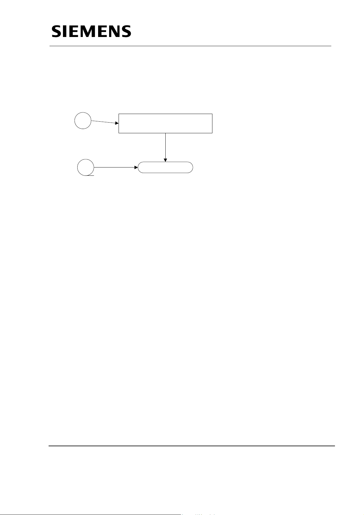
4.6.12 Code 01 : Err signal on D950A active
Start
Is tp test point on D950A
low?
Service Manual
Service Instructions
Yes
Is Vc>3.35v (A test point on
D950A?)
Yes
Whether IGBT V3 is
Short circuited.
NO
Stop
Replace D950A.
NO
YES
NO
Siemens Ltd. Med Division India Version 4.0
Page 48 of 48
 Loading...