

Page 1
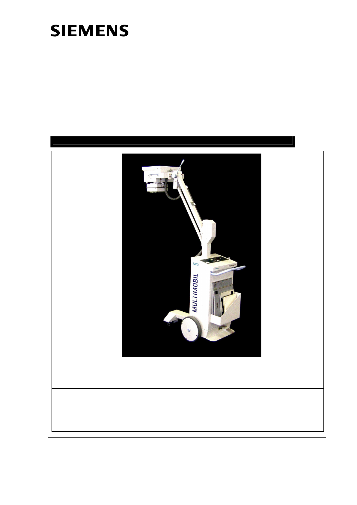
MULTIMOBIL 10
Installation Instructions
SP
© Siemens AG 2003
The reproduction, transmission or
use of this document or its contents
is not permitted without express
written authority. Offenders will be
liable for damages. All rights,
including rights created by patent
grant or registration of a utility
model _or_ design,_are_ reserved.
English
Print No.: SPR8-X01.812.10.02.02 Doc. Gen. Date: 10.05
Replaces: SPR8-X01.812.10.01.02
Page 2
Multimobil 10
Service Manual
Installation Instructions
Med
Installation Instructions
Version: 4.0
The reproduction, transmission or use
of this document or its contents is not
permitted without express written
authority. Offenders will be liable for
damages.
Siemens Ltd. Med Division India Version 4.0
Page 1 of 12
Page 3

Service Manual
Installation Instructions
INDEX
1 INSTALLATION ............................................................................................................................ 3
1.1 S
1.2 O
1.3 RADIATION PROTECTION : ...........................................................................................................4
1.4 MECHANICAL SAFTEY :................................................................................................................ 4
1.5 U
1.6 TRANSPORT AND POSITIONING OF UNIT .......................................................................................6
1.7 P
1.7.1 Mains : .............................................................................................................................6
1.7.2 Interconnections ..............................................................................................................6
2 SWITCHING THE UNIT ON .........................................................................................................7
2.1 F
2.2 COLLIMATOR :............................................................................................................................. 9
2.3 M
2.4 EXPOSURE ...............................................................................................................................10
2.4.1 Sample Exposure: .........................................................................................................11
3 HANDING OVER MULTIMOBIL 10............................................................................................ 12
AFETY PRECAUTIONS................................................................................................................ 3
VERLOAD PROTECTION :........................................................................................................... 4
NPACKING ................................................................................................................................5
RELIMINARY CHECK : ................................................................................................................6
ORMING OF THE CAPACITOR BANK:............................................................................................ 8
OVEMENTS :........................................................................................................................... 10
Siemens Ltd. Med Division India Version 4.0
Page 2 of 12
Page 4

Service Manual
Installation Instructions
1 Installation
1.1 Safety Precautions
General:
It shall be the duty of the installation personnel and the user to ensure that all the
safety measures concerning the unit operation and installation are adhered to.
The unit must be checked for the status of its safety measures at least every year or
any time desired by the user, not exceeding one year.
However, we recommend in the interest of the safety of the patient, the user, and
other personnel to have a yearly drill on operational safety.
If there are any special regulations of the hospital/institute, to be followed over and
above the general safety regulations pertaining to the installation, the same must be
ensured.
Before commencing the operation, the user must convince himself regarding all safety
aspects and their proper functioning. He should also ascertain that all displays and
indicators are functioning as described.
The radiation indication lamp should light only when the exposure is released. In case
the lamp lights in any other condition, the unit should be immediately switched off and
SIEMENS SERVICE DEPARTMENT should be informed.
Any change / or replacement in the unit must be carried out by the manufacturer or a
person authorised by manufacturer ONLY. The record of such work must be
maintained clearly at the site.
Before working on the unit ensure that the Mains is switched OFF.
For completely safe working remove mains plug.
The unit must be OFF before removing or putting back the assemblies.
The protective earthing of sub-assemblies must not be removed in any case.
Siemens Ltd. Med Division India Version 4.0
Page 3 of 12
Page 5

Service Manual
Installation Instructions
1.2 Overload Protection :
The unit is designed to work between 99 V to 121 V on 110 V or 180 V to 265 V on
230 V line ac single phase supply with a 15A socket. For safety purposes 10A HRC
fuses are provided which will blow when a current exceeding 10A sustains for its
response time.
Ensure that the mains socket is properly earthed.
In case of fault if the kV tries to build beyond the safe limit of X-ray tube the protection
circuit blocks the HT.
In case of fault, if the Filament current tries to increase beyond the safe limit the
protection circuit blocks filament boosting.
1.3 Radiation Protection :
Do not put any part of your body in the direct line of radiation.
Collimate the X-ray beam.
Keep maximum possible distance from the object being radiographed. For this
make the best use of 5m of recoilable exposure release switch.
Wear protective clothing.
Monitor radiation received using the personal TLD-badges or pen-dosimeter.
1.4 Mechanical Saftey :
Before releasing arm assembly from its locking position, ensure that the single tank
assembly along with covers, yoke and collimator is in the original position.
In case a difficulty is encountered in releasing the lock, any adjustments or alignments
must be done with complete single tank assembly in the locked position only.
Do not attempt to release the lock by any other means.
The arm will not be counter-balanced if any of the single tank assembly parts like
cover are removed.
Any detection of physical damage of single tank assembly or breaking or loosening of
its parts (except handles) indicates possible danger of upward force the order of 25kg,
when the arm is released from its locked position. In such a situation, it is
recommended to suspend the installation and contact FACTORY for further
clarification.
Siemens Ltd. Med Division India Version 4.0
Page 4 of 12
Page 6

1.5 Unpacking
Service Manual
Installation Instructions
Siemens Ltd. Med Division India Version 4.0
Page 5 of 12
Page 7

Service Manual
Installation Instructions
1.6 Transport and Positioning of Unit
Refer corresponding section on Transporting the Unit and Positioning for Exposures in
the Operating Instructions.
1.7 Preliminary Check :
1.7.1 Mains :
1. Check available mains voltage at the site either 110 V or 230 V AC.
2. Check if the mains voltage is between 99 V to 121 V ac or 180 Vac to 265 Vac
respectively.
3. The unit is set for respective line voltage at the time of despatch from factory.
5. When the mains voltage is less than 205V on 230 V ac line, than the LN contactor
is energised for line condition compensation circuit.
6.Check if the mains resistance is < 1.2 Ω.
1.7.2 Interconnections
Type Description Specifications
Mains
Control - single Tank
D915.X8, X1 Connector 3 Core shielded PVC insulated, kV/mA feedback
D801.X60 Allied Connector 2 Core 1 mm sq. Grey, Collimator Cable
D801.X5 11/12 - D900A 2 Core shielded PVC insulated, Filament cables
D801.X3 0,I,II - D900A 3 Core shielded PVC insulated , Anode Rotation
D960 (out1) and
Earthing terminal Earthing stud 6 mm sq Yel/Green Earth Cable
Interconnections
1 Mains Cable 3 x 1.5 sq.mm
Control Single Tank
U,V - D900A 6 mm sq. Black U & V Cables
capacitor C6
Cable
11 & I2
cable.
D915.X11 to D801.X11 Flat Band 16 core.
D915.X10 to D801.X10 Flat Band 26 Core.
D915.J24 to D932.X1 Flat Band 28 Core.
D915.X20 to D960.X20 to D950A .X20 Flat Band 20 Core.
D915.X12 to D936.X12 Flat Band 14 Core.
D915.X15 to D980.X15 Flat bonded cable K7
D801.X9 to D980 .X9 SMPS Mains cable K12
Wire bunch to D801.X1 10 pin molex connector
Wire bunch to D801.X50 3 pin molex connector
Wire bunch to D801.X18 6 pin molex connector
Contactor CS to X3.D950A Charger cable S4 with 6 pin connector
Bleeder resistor to X9.D950A 3 pin connector discharge cable
The max. Permissible resistance between the earthing terminal in the control and the
single tank is less than 0.2 ohms.
Siemens Ltd. Med Division India Version 4.0
Page 6 of 12
Page 8

2 Switching the unit ON
Service Manual
Installation Instructions
Switch ON the MCB
.
MCB
If the unit is being installed within six months from the date of despatch then the
forming is not required for the Capacitors. Before Switching ON the Unit open
the top panel cover of MM10 control by removing the ornamental screws (2x)
and remove the ST link (jumper pin) on D915 PCB
Switch the Generator ON by actuating momentarily
The Display and radiation Indicator light up.
The kV and mAs display read
for 3 Sec and then the stable mAs value appear. Once the Capacitor Bank is charged
to a value of 355V DC, then the stable kV value appears and it is indicated by a long
Beep
The unit becomes ready for use after this end of setup
After set-up, initial hardware checks and capacitor bank fully charged to 355V DC the
display changes to
the default kV and mAs settings.
The kV & mAs display and settings will now respond to the corresponding switches on
the panel.
Siemens Ltd. Med Division India Version 4.0
Page 7 of 12
Page 9

Service Manual
Installation Instructions
In case of any errors while setting up / hardware check / stand-by operation, the
corresponding Error code will be displayed on the same displays.
e.g. The display will indicate Error 99 in case the unit while setting up/ after setup
detects that last reset of the unit was due to watch-dog timer RESET.
Note: The Control Unit contains Non volatile Memory which retains the last
selected kV and mAs. So the initial display after setup will depend on the last
settings done.
If the unit is being installed after six months from the date of despatch then the
forming for the Capacitors is a must.
2.1 Forming of the Capacitor Bank:
Open the top panel cover of MM10 control by removing the ornamental screws (2x)
and put the ST link (jumper pin) on D915 PCB.
Switch ON the MCB
.
MCB
Switch the Generator ON by actuating momentarily
Then the kV and mAs display read as shown in picture, if there are no initialisation
Errors.
Siemens Ltd. Med Division India Version 4.0
Page 8 of 12
Page 10

Service Manual
Installation Instructions
On D936 keyboard PCB,
1. Press DL-SERV switch once, the display will indicate the present Voltage on the
Capacitor bank.
2. Press once again DL-SERV switch, the display will indicate Pr.1
3. Press again the DL-SERV switch the CS contactor will hold and the
Capacitors will start charging in described steps as follows:
0V – 50 – 100 – 150 – 225 – 300 – 342 V .
Each step will take about 6 minutes, so total procedure of Capacitor bank
Forming will take 36 minutes.
4. Now switch OFF the unit and remove the ST link (jumper pin) on D915 PCB.
2.2 Collimator :
Switch the unit ON
Switch ON the collimator lamp. The collimator lamp will glow for 30 sec ± 5 sec.
Open collimator flaps to the maximum. The light will show square, sharp edges and
clear cross wires.
Close the flaps fully. The light field will show a small square.
Siemens Ltd. Med Division India Version 4.0
Page 9 of 12
Page 11

Service Manual
Installation Instructions
2.3 Movements :
Check arm counterbalancing at all positions.
When the single tank does not remain at the required position, the spring tension
should be adjusted for complete balancing.
Refer Troubleshooting instructions for adjustments of spring tension.
Presence of High Tension
Observe Safety Precautions
Use Radiation Protection
2.4 Exposure
Switch the generator ON.
Set the exposure parameters as 60kV, 10mAs.
Pull the recoilable Exposure Release Switch and release an exposure. The yellow
LED on the top panel will light up for duration equal to exposure time.
Audible indication by a muffled sound from single tank as well as from the buzzer will
confirm the working of the inverter and the exposure.
The LED’s on D915 glow in the following sequence.
S27 – STEP 1(Half press): V22
During exposure : V23
Error indication : V24
In case of an error the corresponding code will be displayed on the seven-segment
display. Refer the service instructions to rectify the error.
Siemens Ltd. Med Division India Version 4.0
Page 10 of 12
Page 12

Service Manual
Installation Instructions
2.4.1 Sample Exposure:
Set 60 kV 16mAs on the panel.
Note kVist and mA ist values on the oscilloscope at the test points n D915.
TP :kV and JR.
Also note the T exp from kV waveform.
Following should be the values.
Kvist : 1v=20kV
3V
Texp = 100ms
JR : (1V = 50mA)
3.2V
Texp = 100ms
Siemens Ltd. Med Division India Version 4.0
Page 11 of 12
Page 13

Service Manual
Installation Instructions
3 Handing Over Multimobil 10
Important:
Hand over the machine after taking sample exposures:
1. Chest : 60KV,12.5 mAs ( +/- 1,2 points)
2. Skull : 70KV,25mAs(+/- 2 points)
3. Extremities : 42KV,6.4 mAs (+/- 2 points)
4. Abdomen : 70KV,25mAs (+/-3 points)
After handing over the Generator, kindly fill the Delivery Confirmation Card and the
feedback report accompanying the Operating Manual and return it to the factory.
In case of any of the Following conditions, Please refer the SERVICE
INSTRUCTIONS:
• Unit is in the “Sleep “ state i.e. with unit ON/OFF there is no display on the Top
panel.
• Unit is working in the standby state, but proper exposure is not obtained, error is
displayed on the Top panel.
• Even in the standby state, there is continuous display of error.
For ensuring the proper operation of the unit, Please refer the OPERATING
INSTRUCTIONS for the user.
Siemens Ltd. Med Division India Version 4.0
Page 12 of 12
 Loading...