

Page 1

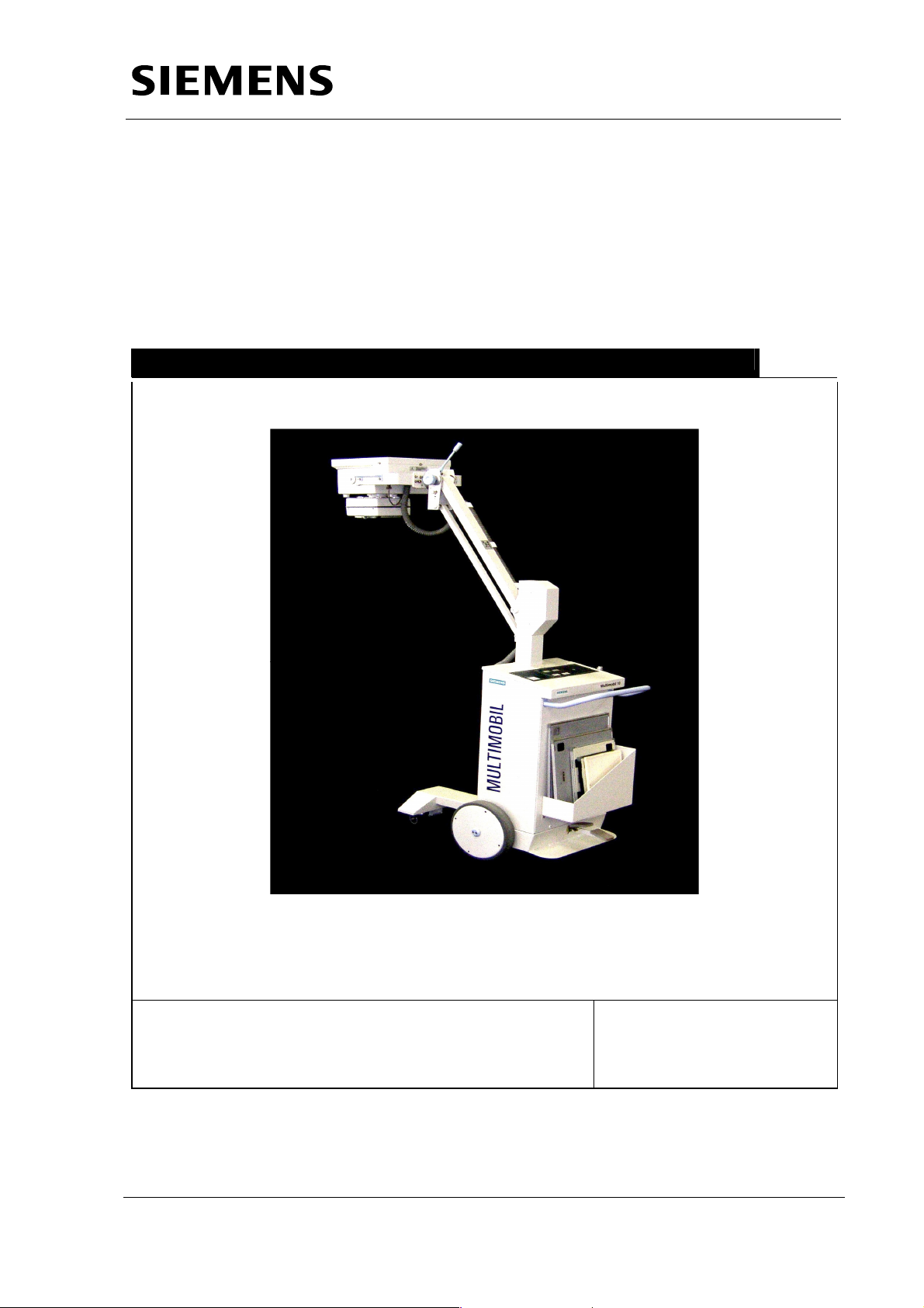
MULTIMOBIL 10
Wiring Diagrams
SP
Wiring Description
© Siemens AG 2005
The reproduction, transmission or
use of this document or its contents
is not permitted without express
written authority. Offenders will be
liable for damages. All rights,
including rights created by patent
grant or registration of a utility
model _or_ design,_are_ reserved.
English
Print No.: SPR8-X01.844.12.01.02 Doc. Gen. Date: 10.05
Replaces: n.a.
Page 2
Multimobil 10
Service Manual
Wiring Description
Med
Wiring Description
Version: 4.0
Copyright © SIEMENS LTD.,MED INDIA
Siemens Ltd. Med India Version 4.0
The reproduction, transmission or use of
this document or its contents is not
permitted without express written
authority. Offenders will be liable for
damages.
Page 1 of 4
Page 3

Service Manual
Wiring Description
INDEX
1. WIRING DESCRIPTION.................................................................................3
Siemens Ltd. Med India Version 4.0
Page 2 of 4
Page 4

Service Manual
Wiring Description
1. Wiring Description
When the MCB is switched ON, Line and Neutral is routed through U1 and
U2 fuses, line filter and mains isolation transformer T1.
Line voltage of 230V or 110V 50/60 Hz is applied to the primary winding of the
mains isolation transformer T1.
At the secondary of the mains isolation transformer T1 0-12V, 0-24V, 0-220V,
260V AC voltages are available. Out of which 0-12V and 0-24 V AC voltages are
routed through a powermat connector (PC1 to be labelled).
• 0-12V AC is applied through R2 resistor, 13 –14 NO contacts of NS contactor,
X1.9 & X1.10 on D801 to collimator.
• 0-24V AC is also routed through powermat connector ( PC1 to be labelled) then
through X1.5 and X1.6 connector, rectified and filtered .This DC voltage of 24 V
is applied across the coils of K2, K3, K4 and K5 relays on D801.
• A voltage of 0-220V AC ( PC2 to be labelled)is applied :
• Between 43-44 NO contacts and 33-34 NO contacts of NS contactor.
• Across the coil of NS contactor through X50, K5 and K4 relays on D801.
• Also between 43-44 NO contacts and 33-34 NO contacts of CS contactor
to D950A card.
• Voltage of 0-260V AC ( PC2 to be labelled) is applied to 13-14 NO, 31-32 NC
contacts of LN contactor to X1.1 connector on D801.
Contacts 21-22 of NS contactor and 21-22 of CS contactor are NC i.e normally
closed, this provides a discharge path for the capacitor bank when the unit is OFF.
Now when the unit is switched ON through D936. K5 relay on D801operates K4
relay on D801 which in turn switches the NS contactor ON by providing 220V AC
across its coil.
With NS contactor ON,
• NO contacts 43-44 and 33-34 close
• 0-220V AC voltage is now available to SMPS D980.
• And through NC contacts of 31-32 of LN contactor, 0-220V AC voltage is
now available to filament invertor circuit on D801.
• NC contacts 21-22 open, breaking the discharge path for the capacitor bank.
After the NS contactor picks up the CS contactor is energised through X10
connector on D801
• Causing NO contacts 43-44 and 33-34 to close thus providing 0-220V AC to
D950A capacitor charger card.
• And releasing the NC contact 21-22, opening the discharge path for the
capacitor bank.
• The DC supply for the Main Inverter D960 is obtained from the capacitor bank.
The primary of the HT Transformer forms the load to D960 along with capacitor
C5 and Inductor L1 of the resonant circuit.
Siemens Ltd. Med India Version 4.0
Page 3 of 4
Page 5

Service Manual
Wiring Description
The line voltage is monitored by the microcontroller, if it falls below 200V AC the LN
contactor picks up through the K3 relay on D801
• Causing NO contact 13-14 to close and routing 0-260V AC from secondary
mains isolation transformer T1 to filament invertor circuit on D801.
• And opening the NC contact 31-32.
When the unit is switched OFF through D936:
• K1 relay on D801 operates and switches off coil voltage to NS contactor,
releasing all NC contacts and closing all NO contacts.
1.1 The CS contactor de-energises, interrupting 0-220VAC to D950A and
closing 21-22 contact to re-establish the discharge path.
Siemens Ltd. Med India Version 4.0
Page 4 of 4
 Loading...