

Page 1

s
MULTIGAS and MULTIGAS+ Modules
Service Manual
Service Manual
Service ManualService Manual
E341.E536U.061.01.02.02
Replaces/Ersetzt:
ASK-T876-02-7600
EM Guidelines, 1997-04-02
Product Drawing
E341.E536U.061.01.01.02
Page 2

ADVISORY
Siemens is liable for the safety of its equipment only if maintenance, repair, and modifications are performed by
authorized personnel, and if components affecting the equipment's safety are replaced with Siemens spare parts.
Any modification or repair not done by Siemens personnel must be documented. Such documentation must:
• be signed and dated
• contain the name of the company performing the work
• describe the changes made
• describe any equipment performance changes.
It is the responsibility of the user to contact Siemens to determine warranty status and/or liabilities if other than
an authorized Siemens Service Representative repairs or makes modifications to medical devices.
Page 3

Table of Contents
Chapter 1: Introduction . . . . . . . . . . . . . . . . . . . . . . . . . . . . . . . . . . . . . . . . . . . . . . . . . . . 1
1 Overview . . . . . . . . . . . . . . . . . . . . . . . . . . . . . . . . . . . . . . . . . . . . . . . . . . . . . . . . . . . . . . . . . . . . . . . . . . 1
Figure 1-1 MultiGas and MultiGas+ Modules - Rear Views . . . . . . . . . . . . . . . . . . . . . . . . . . . . . . . . . . 1
2 Hardware Installation . . . . . . . . . . . . . . . . . . . . . . . . . . . . . . . . . . . . . . . . . . . . . . . . . . . . . . . . . . . . . . . . . 1
3 Service Strategy . . . . . . . . . . . . . . . . . . . . . . . . . . . . . . . . . . . . . . . . . . . . . . . . . . . . . . . . . . . . . . . . . . . . . 2
4 Preventative Maintenance . . . . . . . . . . . . . . . . . . . . . . . . . . . . . . . . . . . . . . . . . . . . . . . . . . . . . . . . . . . . . 2
5 Recommended Tools & Test Equipment . . . . . . . . . . . . . . . . . . . . . . . . . . . . . . . . . . . . . . . . . . . . . . . . . . 3
Chapter 2: Functional Description . . . . . . . . . . . . . . . . . . . . . . . . . . . . . . . . . . . . . . . . . . 5
1 Introduction . . . . . . . . . . . . . . . . . . . . . . . . . . . . . . . . . . . . . . . . . . . . . . . . . . . . . . . . . . . . . . . . . . . . . . . . 5
Figure 2-1 Functional MGM Block Diagram . . . . . . . . . . . . . . . . . . . . . . . . . . . . . . . . . . . . . . . . . . . . . . 5
2 Overall Functionality . . . . . . . . . . . . . . . . . . . . . . . . . . . . . . . . . . . . . . . . . . . . . . . . . . . . . . . . . . . . . . . . . . 5
3 Method of Operation . . . . . . . . . . . . . . . . . . . . . . . . . . . . . . . . . . . . . . . . . . . . . . . . . . . . . . . . . . . . . . . . . 5
Figure 2-2 Anesthetic Gas Subsystem Functional Block Diagram . . . . . . . . . . . . . . . . . . . . . . . . . . . . . 6
4 Subassemblies, Modules and Components . . . . . . . . . . . . . . . . . . . . . . . . . . . . . . . . . . . . . . . . . . . . . . . 6
5 Anesthetic Gas Subsystem . . . . . . . . . . . . . . . . . . . . . . . . . . . . . . . . . . . . . . . . . . . . . . . . . . . . . . . . . . . . 6
6 Main System . . . . . . . . . . . . . . . . . . . . . . . . . . . . . . . . . . . . . . . . . . . . . . . . . . . . . . . . . . . . . . . . . . . . . . . 6
7 Agent Measurement Analyzer . . . . . . . . . . . . . . . . . . . . . . . . . . . . . . . . . . . . . . . . . . . . . . . . . . . . . . . . . . 7
Figure 2-3 Agent Measurement Analyzer Functional Block Diagram . . . . . . . . . . . . . . . . . . . . . . . . . . . 8
Figure 2-4 Agent Identification Analyzer (AIDA) Functional Block Diagram . . . . . . . . . . . . . . . . . . . . . . 9
8 Agent Identification Analyzer . . . . . . . . . . . . . . . . . . . . . . . . . . . . . . . . . . . . . . . . . . . . . . . . . . . . . . . . . . . 9
9 Oxygen Analyzer . . . . . . . . . . . . . . . . . . . . . . . . . . . . . . . . . . . . . . . . . . . . . . . . . . . . . . . . . . . . . . . . . . . 10
9.1 Paramagnetic O2 Measurement . . . . . . . . . . . . . . . . . . . . . . . . . . . . . . . . . . . . . . . . . . . . . . . . . . . . 10
9.2 Electrochemical O2 Measurement . . . . . . . . . . . . . . . . . . . . . . . . . . . . . . . . . . . . . . . . . . . . . . . . . . 10
10Pneumatic System . . . . . . . . . . . . . . . . . . . . . . . . . . . . . . . . . . . . . . . . . . . . . . . . . . . . . . . . . . . . . . . . . . 10
Figure 2-5 Pneumatics Block Diagram (excerpt from Figure 2-2.) . . . . . . . . . . . . . . . . . . . . . . . . . . . . 11
Table 2-1 Pump Flow Rates . . . . . . . . . . . . . . . . . . . . . . . . . . . . . . . . . . . . . . . . . . . . . . . . . . . . . . 11
11Self-Test . . . . . . . . . . . . . . . . . . . . . . . . . . . . . . . . . . . . . . . . . . . . . . . . . . . . . . . . . . . . . . . . . . . . . . . . . . 12
12Calibration . . . . . . . . . . . . . . . . . . . . . . . . . . . . . . . . . . . . . . . . . . . . . . . . . . . . . . . . . . . . . . . . . . . . . . . . 12
12.1Factory Calibration . . . . . . . . . . . . . . . . . . . . . . . . . . . . . . . . . . . . . . . . . . . . . . . . . . . . . . . . . . . . . . . 12
12.2Field Span Calibration . . . . . . . . . . . . . . . . . . . . . . . . . . . . . . . . . . . . . . . . . . . . . . . . . . . . . . . . . . . . 12
12.3Zero Calibration . . . . . . . . . . . . . . . . . . . . . . . . . . . . . . . . . . . . . . . . . . . . . . . . . . . . . . . . . . . . . . . . . 12
12.4Storage of Calibration Data . . . . . . . . . . . . . . . . . . . . . . . . . . . . . . . . . . . . . . . . . . . . . . . . . . . . . . . . 13
12.5Calibration of Agent Measurement Analyzer . . . . . . . . . . . . . . . . . . . . . . . . . . . . . . . . . . . . . . . . . . . 13
12.5.1 Factory Calibration . . . . . . . . . . . . . . . . . . . . . . . . . . . . . . . . . . . . . . . . . . . . . . . . . . . . . . . . 13
12.5.2 Field Span Calibration . . . . . . . . . . . . . . . . . . . . . . . . . . . . . . . . . . . . . . . . . . . . . . . . . . . . . 13
12.5.3 Zero Calibration . . . . . . . . . . . . . . . . . . . . . . . . . . . . . . . . . . . . . . . . . . . . . . . . . . . . . . . . . . 13
ASK-T876-02-7600 Siemens Medical Systems, EM-PCS Danvers i
mgm2.sm.fm/11-00/kaupp
Page 4

MGM and MGM+ Modules Service Manual
12.6Agent Identification Analyzer . . . . . . . . . . . . . . . . . . . . . . . . . . . . . . . . . . . . . . . . . . . . . . . . . . . . . . . 14
12.6.1 Factory Calibration . . . . . . . . . . . . . . . . . . . . . . . . . . . . . . . . . . . . . . . . . . . . . . . . . . . . . . . . 14
12.6.2 Field Span Calibration . . . . . . . . . . . . . . . . . . . . . . . . . . . . . . . . . . . . . . . . . . . . . . . . . . . . . 14
12.6.3 Zero Calibration . . . . . . . . . . . . . . . . . . . . . . . . . . . . . . . . . . . . . . . . . . . . . . . . . . . . . . . . . . 14
12.7Paramagnetic O2 Analyzer . . . . . . . . . . . . . . . . . . . . . . . . . . . . . . . . . . . . . . . . . . . . . . . . . . . . . . . . . 14
12.7.1 Factory Calibration . . . . . . . . . . . . . . . . . . . . . . . . . . . . . . . . . . . . . . . . . . . . . . . . . . . . . . . . 14
12.7.2 Field Span Calibration . . . . . . . . . . . . . . . . . . . . . . . . . . . . . . . . . . . . . . . . . . . . . . . . . . . . . 14
12.7.3 Field Zero Calibration . . . . . . . . . . . . . . . . . . . . . . . . . . . . . . . . . . . . . . . . . . . . . . . . . . . . . . 14
12.8Fuel Cell Type O2 Analyzer Calibration . . . . . . . . . . . . . . . . . . . . . . . . . . . . . . . . . . . . . . . . . . . . . . . 14
12.8.1 Factory Calibration . . . . . . . . . . . . . . . . . . . . . . . . . . . . . . . . . . . . . . . . . . . . . . . . . . . . . . . . 14
12.8.2 Field Span and Zero Calibration . . . . . . . . . . . . . . . . . . . . . . . . . . . . . . . . . . . . . . . . . . . . . .15
12.8.3 Field Zero Calibration . . . . . . . . . . . . . . . . . . . . . . . . . . . . . . . . . . . . . . . . . . . . . . . . . . . . . . 15
12.9Pneumatic System Calibration . . . . . . . . . . . . . . . . . . . . . . . . . . . . . . . . . . . . . . . . . . . . . . . . . . . . . . 15
12.9.1 Factory Calibration . . . . . . . . . . . . . . . . . . . . . . . . . . . . . . . . . . . . . . . . . . . . . . . . . . . . . . . . 15
12.9.2 Field Flow Rate Calibration . . . . . . . . . . . . . . . . . . . . . . . . . . . . . . . . . . . . . . . . . . . . . . . . . 15
13Software . . . . . . . . . . . . . . . . . . . . . . . . . . . . . . . . . . . . . . . . . . . . . . . . . . . . . . . . . . . . . . . . . . . . . . . . . 15
13.1AMA Data Acquisition . . . . . . . . . . . . . . . . . . . . . . . . . . . . . . . . . . . . . . . . . . . . . . . . . . . . . . . . . . . . 15
Figure 2-6 Software Functional Block Diagram . . . . . . . . . . . . . . . . . . . . . . . . . . . . . . . . . . . . . . . . . .16
13.2AMA Signal Processing . . . . . . . . . . . . . . . . . . . . . . . . . . . . . . . . . . . . . . . . . . . . . . . . . . . . . . . . . . . 16
13.3AMA Compensation . . . . . . . . . . . . . . . . . . . . . . . . . . . . . . . . . . . . . . . . . . . . . . . . . . . . . . . . . . . . . 17
13.4Patient Data Derivation . . . . . . . . . . . . . . . . . . . . . . . . . . . . . . . . . . . . . . . . . . . . . . . . . . . . . . . . . . . 17
13.5Host System Communications . . . . . . . . . . . . . . . . . . . . . . . . . . . . . . . . . . . . . . . . . . . . . . . . . . . . . 17
13.6Anesthetic Gas Subsystem / Host System Communications . . . . . . . . . . . . . . . . . . . . . . . . . . . . . . 18
13.7AIDA Communication . . . . . . . . . . . . . . . . . . . . . . . . . . . . . . . . . . . . . . . . . . . . . . . . . . . . . . . . . . . . 18
13.8MGM/AMA Control . . . . . . . . . . . . . . . . . . . . . . . . . . . . . . . . . . . . . . . . . . . . . . . . . . . . . . . . . . . . . . 18
13.9AIDA Data Acquisition . . . . . . . . . . . . . . . . . . . . . . . . . . . . . . . . . . . . . . . . . . . . . . . . . . . . . . . . . . . . 19
13.10AIDA Signal Processing . . . . . . . . . . . . . . . . . . . . . . . . . . . . . . . . . . . . . . . . . . . . . . . . . . . . . . . . . . 19
13.11AIDA Agent Identification . . . . . . . . . . . . . . . . . . . . . . . . . . . . . . . . . . . . . . . . . . . . . . . . . . . . . . . . . 19
13.12AIDA Control . . . . . . . . . . . . . . . . . . . . . . . . . . . . . . . . . . . . . . . . . . . . . . . . . . . . . . . . . . . . . . . . . . 20
Chapter 3: Removing / Installing Parts . . . . . . . . . . . . . . . . . . . . . . . . . . . . . . . . . . . . . 21
1 Introduction . . . . . . . . . . . . . . . . . . . . . . . . . . . . . . . . . . . . . . . . . . . . . . . . . . . . . . . . . . . . . . . . . . . . . . . 21
1.1 Opening Module . . . . . . . . . . . . . . . . . . . . . . . . . . . . . . . . . . . . . . . . . . . . . . . . . . . . . . . . . . . . . . . . 21
Figure 3-1 Pump and Pneumatic Subassemblies in MGM+ . . . . . . . . . . . . . . . . . . . . . . . . . . . . . . . . . 22
2 MGM+ . . . . . . . . . . . . . . . . . . . . . . . . . . . . . . . . . . . . . . . . . . . . . . . . . . . . . . . . . . . . . . . . . . . . . . . . . . . 22
2.1 Pneumatic Tubing Subassemblies . . . . . . . . . . . . . . . . . . . . . . . . . . . . . . . . . . . . . . . . . . . . . . . . . . . 22
2.1.1 Removing Pneumatic Subassemblies . . . . . . . . . . . . . . . . . . . . . . . . . . . . . . . . . . . . . . . . . 22
2.1.2 Installing Pneumatic Subassemblies . . . . . . . . . . . . . . . . . . . . . . . . . . . . . . . . . . . . . . . . . . 22
Figure 3-2 Pump and Pneumatic Subassemblies in MGM (Slo-O2) . . . . . . . . . . . . . . . . . . . . . . . . . . . 23
ii Siemens Medical Systems, EM-PCS, Danvers ASK-T876-02-7600
mgm2.sm.fm/11-00/kaupp
Page 5

Service Manual MGM and MGM+ Modules
3 MGM (Slo-O2) . . . . . . . . . . . . . . . . . . . . . . . . . . . . . . . . . . . . . . . . . . . . . . . . . . . . . . . . . . . . . . . . . . . . . 23
3.1 Replacing Pneumatic Subassemblies . . . . . . . . . . . . . . . . . . . . . . . . . . . . . . . . . . . . . . . . . . . . . . . . 23
3.1.1 Removing Pneumatic Tubing . . . . . . . . . . . . . . . . . . . . . . . . . . . . . . . . . . . . . . . . . . . . . . . . 23
3.1.2 Installing Pneumatic Tubing . . . . . . . . . . . . . . . . . . . . . . . . . . . . . . . . . . . . . . . . . . . . . . . . . 24
4 Replacing Pump . . . . . . . . . . . . . . . . . . . . . . . . . . . . . . . . . . . . . . . . . . . . . . . . . . . . . . . . . . . . . . . . . . . . 24
4.1 Removing Pump . . . . . . . . . . . . . . . . . . . . . . . . . . . . . . . . . . . . . . . . . . . . . . . . . . . . . . . . . . . . . . . . 24
4.2 Installing Pump . . . . . . . . . . . . . . . . . . . . . . . . . . . . . . . . . . . . . . . . . . . . . . . . . . . . . . . . . . . . . . . . . 25
5 Pump Filter Removal/Replacement Procedure . . . . . . . . . . . . . . . . . . . . . . . . . . . . . . . . . . . . . . . . . . . . 25
5.1 Removal . . . . . . . . . . . . . . . . . . . . . . . . . . . . . . . . . . . . . . . . . . . . . . . . . . . . . . . . . . . . . . . . . . . . . . . 25
5.2 Replacement . . . . . . . . . . . . . . . . . . . . . . . . . . . . . . . . . . . . . . . . . . . . . . . . . . . . . . . . . . . . . . . . . . . 25
6 Nafion® or other Tubing Removal/Replacement Procedure . . . . . . . . . . . . . . . . . . . . . . . . . . . . . . . . . . 25
6.1 Removal . . . . . . . . . . . . . . . . . . . . . . . . . . . . . . . . . . . . . . . . . . . . . . . . . . . . . . . . . . . . . . . . . . . . . . . 25
6.2 Replacement . . . . . . . . . . . . . . . . . . . . . . . . . . . . . . . . . . . . . . . . . . . . . . . . . . . . . . . . . . . . . . . . . . . 25
7 Room Air Filter Removal/Replacement Procedure . . . . . . . . . . . . . . . . . . . . . . . . . . . . . . . . . . . . . . . . .26
7.1 Removal . . . . . . . . . . . . . . . . . . . . . . . . . . . . . . . . . . . . . . . . . . . . . . . . . . . . . . . . . . . . . . . . . . . . . . . 26
7.2 Replacement . . . . . . . . . . . . . . . . . . . . . . . . . . . . . . . . . . . . . . . . . . . . . . . . . . . . . . . . . . . . . . . . . . . 26
8 AMA Analyzer Head Removal/Replacement Procedure . . . . . . . . . . . . . . . . . . . . . . . . . . . . . . . . . . . . . 26
8.1 Removal . . . . . . . . . . . . . . . . . . . . . . . . . . . . . . . . . . . . . . . . . . . . . . . . . . . . . . . . . . . . . . . . . . . . . . . 26
8.2 Replacement . . . . . . . . . . . . . . . . . . . . . . . . . . . . . . . . . . . . . . . . . . . . . . . . . . . . . . . . . . . . . . . . . . . 26
9 AMA Sample Cell Removal/Replacement Procedure . . . . . . . . . . . . . . . . . . . . . . . . . . . . . . . . . . . . . . . 26
9.1 Removal . . . . . . . . . . . . . . . . . . . . . . . . . . . . . . . . . . . . . . . . . . . . . . . . . . . . . . . . . . . . . . . . . . . . . . . 26
Figure 3-3 System PC Board . . . . . . . . . . . . . . . . . . . . . . . . . . . . . . . . . . . . . . . . . . . . . . . . . . . . . . . . 27
9.2 Replacement . . . . . . . . . . . . . . . . . . . . . . . . . . . . . . . . . . . . . . . . . . . . . . . . . . . . . . . . . . . . . . . . . . . 27
10Agent ID Analyzer Removal/Replacement Procedure . . . . . . . . . . . . . . . . . . . . . . . . . . . . . . . . . . . . . . .27
10.1Removal . . . . . . . . . . . . . . . . . . . . . . . . . . . . . . . . . . . . . . . . . . . . . . . . . . . . . . . . . . . . . . . . . . . . . . . 27
10.2Replacement . . . . . . . . . . . . . . . . . . . . . . . . . . . . . . . . . . . . . . . . . . . . . . . . . . . . . . . . . . . . . . . . . . . 27
11MGM System Board Removal/Replacement Procedure . . . . . . . . . . . . . . . . . . . . . . . . . . . . . . . . . . . . . 27
11.1Removal . . . . . . . . . . . . . . . . . . . . . . . . . . . . . . . . . . . . . . . . . . . . . . . . . . . . . . . . . . . . . . . . . . . . . . . 27
11.2Replacement . . . . . . . . . . . . . . . . . . . . . . . . . . . . . . . . . . . . . . . . . . . . . . . . . . . . . . . . . . . . . . . . . . . 28
12Fast O2 Sensor Assembly Removal/Replacement Procedure . . . . . . . . . . . . . . . . . . . . . . . . . . . . . . . . . 28
12.1Removal . . . . . . . . . . . . . . . . . . . . . . . . . . . . . . . . . . . . . . . . . . . . . . . . . . . . . . . . . . . . . . . . . . . . . . . 28
Figure 3-4 MGM Module Rear View . . . . . . . . . . . . . . . . . . . . . . . . . . . . . . . . . . . . . . . . . . . . . . . . . . 28
Figure 3-5 Pneumatic Tubing Disconnection Points . . . . . . . . . . . . . . . . . . . . . . . . . . . . . . . . . . . . . . . 28
Figure 3-6 Rear Panel Subassembly . . . . . . . . . . . . . . . . . . . . . . . . . . . . . . . . . . . . . . . . . . . . . . . . . . . 29
12.2Replacement . . . . . . . . . . . . . . . . . . . . . . . . . . . . . . . . . . . . . . . . . . . . . . . . . . . . . . . . . . . . . . . . . . . 29
13CAN PC Board Removal/Replacement Procedure . . . . . . . . . . . . . . . . . . . . . . . . . . . . . . . . . . . . . . . . . .29
13.1Removal . . . . . . . . . . . . . . . . . . . . . . . . . . . . . . . . . . . . . . . . . . . . . . . . . . . . . . . . . . . . . . . . . . . . . . . 29
13.2Replacement . . . . . . . . . . . . . . . . . . . . . . . . . . . . . . . . . . . . . . . . . . . . . . . . . . . . . . . . . . . . . . . . . . . 30
ASK-T876-02-7600 Siemens Medical Systems, EM-PCS Danvers iii
mgm2.sm.fm/11-00/kaupp
Page 6

MGM and MGM+ Modules Service Manual
14Power Supply Removal/Replacement Procedure . . . . . . . . . . . . . . . . . . . . . . . . . . . . . . . . . . . . . . . . . .30
14.1Removal . . . . . . . . . . . . . . . . . . . . . . . . . . . . . . . . . . . . . . . . . . . . . . . . . . . . . . . . . . . . . . . . . . . . . . . 30
14.2Replacement . . . . . . . . . . . . . . . . . . . . . . . . . . . . . . . . . . . . . . . . . . . . . . . . . . . . . . . . . . . . . . . . . . . 30
15Solenoid #1 & #3 Removal/Replacement Procedure . . . . . . . . . . . . . . . . . . . . . . . . . . . . . . . . . . . . . . . .30
15.1Removal . . . . . . . . . . . . . . . . . . . . . . . . . . . . . . . . . . . . . . . . . . . . . . . . . . . . . . . . . . . . . . . . . . . . . . . 30
15.2Replacement . . . . . . . . . . . . . . . . . . . . . . . . . . . . . . . . . . . . . . . . . . . . . . . . . . . . . . . . . . . . . . . . . . . 30
16Solenoid #2 Removal/Replacement Procedure . . . . . . . . . . . . . . . . . . . . . . . . . . . . . . . . . . . . . . . . . . . . 30
16.1Removal . . . . . . . . . . . . . . . . . . . . . . . . . . . . . . . . . . . . . . . . . . . . . . . . . . . . . . . . . . . . . . . . . . . . . . . 30
16.2Replacement . . . . . . . . . . . . . . . . . . . . . . . . . . . . . . . . . . . . . . . . . . . . . . . . . . . . . . . . . . . . . . . . . . . 30
17NVRAM Transfer Procedure . . . . . . . . . . . . . . . . . . . . . . . . . . . . . . . . . . . . . . . . . . . . . . . . . . . . . . . . . . 31
17.1Introduction . . . . . . . . . . . . . . . . . . . . . . . . . . . . . . . . . . . . . . . . . . . . . . . . . . . . . . . . . . . . . . . . . . . . 31
17.2Equipment required . . . . . . . . . . . . . . . . . . . . . . . . . . . . . . . . . . . . . . . . . . . . . . . . . . . . . . . . . . . . . . 31
17.3NVRAM Transfer procedure . . . . . . . . . . . . . . . . . . . . . . . . . . . . . . . . . . . . . . . . . . . . . . . . . . . . . . . 31
Chapter 4: Adjustment / Calibration . . . . . . . . . . . . . . . . . . . . . . . . . . . . . . . . . . . . . . . 33
1 Recommended Tools & Test Equipment . . . . . . . . . . . . . . . . . . . . . . . . . . . . . . . . . . . . . . . . . . . . . . . . . 33
2 Leakage Check Procedure . . . . . . . . . . . . . . . . . . . . . . . . . . . . . . . . . . . . . . . . . . . . . . . . . . . . . . . . . . . . 33
3 Pump Test . . . . . . . . . . . . . . . . . . . . . . . . . . . . . . . . . . . . . . . . . . . . . . . . . . . . . . . . . . . . . . . . . . . . . . . . 34
4 O2 Calibration . . . . . . . . . . . . . . . . . . . . . . . . . . . . . . . . . . . . . . . . . . . . . . . . . . . . . . . . . . . . . . . . . . . . . 34
5 Pump Flow Rate Adjustment Procedure . . . . . . . . . . . . . . . . . . . . . . . . . . . . . . . . . . . . . . . . . . . . . . . . . 35
6 Agent Detection and Analysis Calibration . . . . . . . . . . . . . . . . . . . . . . . . . . . . . . . . . . . . . . . . . . . . . . . . 35
Figure 4-1 Gas Calibration / Test Setup . . . . . . . . . . . . . . . . . . . . . . . . . . . . . . . . . . . . . . . . . . . . . . . . 36
Chapter 5: Troubleshooting . . . . . . . . . . . . . . . . . . . . . . . . . . . . . . . . . . . . . . . . . . . . . . 37
1 Agent Measurement Analyzer Head) . . . . . . . . . . . . . . . . . . . . . . . . . . . . . . . . . . . . . . . . . . . . . . . . . . . . 37
Table 5-1 AMA Analyzer Head Problems 37
2 Agent Measurement Analyzer Optical Path . . . . . . . . . . . . . . . . . . . . . . . . . . . . . . . . . . . . . . . . . . . . . . 37
Table 5-2 AMA Optical Path Problems . . . . . . . . . . . . . . . . . . . . . . . . . . . . . . . . . . . . . . . . . . . . . . 37
3 Agent Identification Analyzer Head . . . . . . . . . . . . . . . . . . . . . . . . . . . . . . . . . . . . . . . . . . . . . . . . . . . . . 38
Table 5-3 AIDA Analyzer Head Problems . . . . . . . . . . . . . . . . . . . . . . . . . . . . . . . . . . . . . . . . . . . . 38
4 Power Supply . . . . . . . . . . . . . . . . . . . . . . . . . . . . . . . . . . . . . . . . . . . . . . . . . . . . . . . . . . . . . . . . . . . . . . 39
Table 5-4 Power Supply Problems . . . . . . . . . . . . . . . . . . . . . . . . . . . . . . . . . . . . . . . . . . . . . . . . .39
5 O2 Sensor . . . . . . . . . . . . . . . . . . . . . . . . . . . . . . . . . . . . . . . . . . . . . . . . . . . . . . . . . . . . . . . . . . . . . . . . 39
Table 5-5 O2 Problems . . . . . . . . . . . . . . . . . . . . . . . . . . . . . . . . . . . . . . . . . . . . . . . . . . . . . . . . . . 39
6 Sample Delivery Subsystem . . . . . . . . . . . . . . . . . . . . . . . . . . . . . . . . . . . . . . . . . . . . . . . . . . . . . . . . . . 41
Table 5-6 Sample Delivery Subsystem Problem . . . . . . . . . . . . . . . . . . . . . . . . . . . . . . . . . . . . . . . 41
7 Gas Flow Problems . . . . . . . . . . . . . . . . . . . . . . . . . . . . . . . . . . . . . . . . . . . . . . . . . . . . . . . . . . . . . . . . . 41
Table 5-7 Gas Flow Problems . . . . . . . . . . . . . . . . . . . . . . . . . . . . . . . . . . . . . . . . . . . . . . . . . . . . . 41
iv Siemens Medical Systems, EM-PCS, Danvers ASK-T876-02-7600
mgm2.sm.fm/11-00/kaupp
Page 7

Service Manual MGM and MGM+ Modules
8 Bad MGM System Board suspected . . . . . . . . . . . . . . . . . . . . . . . . . . . . . . . . . . . . . . . . . . . . . . . . . . . 41
Table 5-8 MGM System Board Problems . . . . . . . . . . . . . . . . . . . . . . . . . . . . . . . . . . . . . . . . . . . . 41
9 MGM System Board Test Points, Jumpers, & Connectors . . . . . . . . . . . . . . . . . . . . . . . . . . . . . . . . . . . 42
Table 5-9 MGM System Board Test Points . . . . . . . . . . . . . . . . . . . . . . . . . . . . . . . . . . . . . . . . . . 42
Table 5-10Connector Functions . . . . . . . . . . . . . . . . . . . . . . . . . . . . . . . . . . . . . . . . . . . . . . . . . . . . 43
Table 5-11Jumpers, Functions, and Settings . . . . . . . . . . . . . . . . . . . . . . . . . . . . . . . . . . . . . . . . . . 44
Table 5-12O2 Jumper Configuration . . . . . . . . . . . . . . . . . . . . . . . . . . . . . . . . . . . . . . . . . . . . . . . . 44
Chapter 6: Functional Verification . . . . . . . . . . . . . . . . . . . . . . . . . . . . . . . . . . . . . . . . . 45
1 Pneumatics Leakage Check . . . . . . . . . . . . . . . . . . . . . . . . . . . . . . . . . . . . . . . . . . . . . . . . . . . . . . . . . . . 45
2 Pump Flow Rate Verification . . . . . . . . . . . . . . . . . . . . . . . . . . . . . . . . . . . . . . . . . . . . . . . . . . . . . . . . . . 45
3 Gas Identification Verification . . . . . . . . . . . . . . . . . . . . . . . . . . . . . . . . . . . . . . . . . . . . . . . . . . . . . . . . . . 45
4 Safety Tests . . . . . . . . . . . . . . . . . . . . . . . . . . . . . . . . . . . . . . . . . . . . . . . . . . . . . . . . . . . . . . . . . . . . . . . 46
4.1 Resistance Test . . . . . . . . . . . . . . . . . . . . . . . . . . . . . . . . . . . . . . . . . . . . . . . . . . . . . . . . . . . . . . . . . 46
4.2 Chassis Leakage Current Tests . . . . . . . . . . . . . . . . . . . . . . . . . . . . . . . . . . . . . . . . . . . . . . . . . . . . . 46
Figure 4-2 Leakage Current Tests Block Diagram . . . . . . . . . . . . . . . . . . . . . . . . . . . . . . . . . . . . . . . . 46
Appendix A: Spare / Exchange Parts . . . . . . . . . . . . . . . . . . . . . . . . . . . . . . . . . . . . . . . 47
Figure A-1 MultiGas Module (Fuel Cell Type Sensor) Pneumatics . . . . . . . . . . . . . . . . . . . . . . . . . . 49
Figure A-2 MultiGas+ Module (Paramagnetic Sensor) Pneumatics . . . . . . . . . . . . . . . . . . . . . . . . . 49
Figure A-3 MultilGas Module (Fuel Cell Type Sensor) Cable Interconnections . . . . . . . . . . . . . . . . . 50
Figure A-4 MultilGas+ Module (Paramagnetic Sensor) Cable Interconnections . . . . . . . . . . . . . . . . 51
Figure A-5 MGM / MGM+ Selected Component Locations . . . . . . . . . . . . . . . . . . . . . . . . . . . . . . . 53
Figure A-6 MGM / MGM+ Cover and Mounting Feet . . . . . . . . . . . . . . . . . . . . . . . . . . . . . . . . . . . 53
Figure A-7 MultiGas / MultiGas+ Modules . . . . . . . . . . . . . . . . . . . . . . . . . . . . . . . . . . . . . . . . . . . . 54
Appendix B: Exploded-View Drawings . . . . . . . . . . . . . . . . . . . . . . . . . . . . . . . . . . . . . 55
Figure B-1 MultiGas Module - Exploded View . . . . . . . . . . . . . . . . . . . . . . . . . . . . . . . . . . . . . . . . . 55
Figure B-2 MultiGas+ Module - Exploded View . . . . . . . . . . . . . . . . . . . . . . . . . . . . . . . . . . . . . . . . 56
Figure B-3 MultiGas Module Rear Panel Subassembly . . . . . . . . . . . . . . . . . . . . . . . . . . . . . . . . . . 57
Figure B-4 MultiGas+ Module Rear Panel Subassembly . . . . . . . . . . . . . . . . . . . . . . . . . . . . . . . . . 57
Figure B-5 Agent Measurement Analyzer / Agent Identification Analyzer Subassembly . . . . . . . . . 58
Figure B-6 MGM Top Cover and Mount . . . . . . . . . . . . . . . . . . . . . . . . . . . . . . . . . . . . . . . . . . . . . . 58
Figure B-7 MGM System Board Layout . . . . . . . . . . . . . . . . . . . . . . . . . . . . . . . . . . . . . . . . . . . . . . 59
Appendix C: Functional Verification . . . . . . . . . . . . . . . . . . . . . . . . . . . . . . . . . . . . . . . 61
Appendix D: Disease Prevention . . . . . . . . . . . . . . . . . . . . . . . . . . . . . . . . . . . . . . . . . . 63
1 Siemens Disease Prevention Policy Statement . . . . . . . . . . . . . . . . . . . . . . . . . . . . . . . . . . . . . . . . . . . . 63
ASK-T876-02-7600 Siemens Medical Systems, EM-PCS Danvers v
mgm2.sm.fm/11-00/kaupp
Page 8

MGM and MGM+ Modules Service Manual
2 Know the Facts . . . . . . . . . . . . . . . . . . . . . . . . . . . . . . . . . . . . . . . . . . . . . . . . . . . . . . . . . . . . . . . . . . . . 63
2.1 Types of Viruses . . . . . . . . . . . . . . . . . . . . . . . . . . . . . . . . . . . . . . . . . . . . . . . . . . . . . . . . . . . . . . . . 63
2.2 Facts About ARC, AIDS, Hepatitis B, and TB . . . . . . . . . . . . . . . . . . . . . . . . . . . . . . . . . . . . . . . . . . 63
3 Environmental Controls . . . . . . . . . . . . . . . . . . . . . . . . . . . . . . . . . . . . . . . . . . . . . . . . . . . . . . . . . . . . . . 64
4 Protocol for Servicing the MGM . . . . . . . . . . . . . . . . . . . . . . . . . . . . . . . . . . . . . . . . . . . . . . . . . . . . . . . 65
4.1 Preparation for Repair . . . . . . . . . . . . . . . . . . . . . . . . . . . . . . . . . . . . . . . . . . . . . . . . . . . . . . . . . . . . 65
4.2 Precautions During Repair . . . . . . . . . . . . . . . . . . . . . . . . . . . . . . . . . . . . . . . . . . . . . . . . . . . . . . . . . 65
4.3 After Repair . . . . . . . . . . . . . . . . . . . . . . . . . . . . . . . . . . . . . . . . . . . . . . . . . . . . . . . . . . . . . . . . . . . . 65
4.4 Disposing of Pneumatic System Components . . . . . . . . . . . . . . . . . . . . . . . . . . . . . . . . . . . . . . . . . 66
5 Accidental Skin Puncture Procedure . . . . . . . . . . . . . . . . . . . . . . . . . . . . . . . . . . . . . . . . . . . . . . . . . . . . 66
6 Disease Prevention Supplies . . . . . . . . . . . . . . . . . . . . . . . . . . . . . . . . . . . . . . . . . . . . . . . . . . . . . . . . . . 66
Appendix E: Supplemental Documentation . . . . . . . . . . . . . . . . . . . . . . . . . . . . . . . . . 67
1 Introduction . . . . . . . . . . . . . . . . . . . . . . . . . . . . . . . . . . . . . . . . . . . . . . . . . . . . . . . . . . . . . . . . . . . . . . . 67
2 Hardware Installation . . . . . . . . . . . . . . . . . . . . . . . . . . . . . . . . . . . . . . . . . . . . . . . . . . . . . . . . . . . . . . . . 67
vi Siemens Medical Systems, EM-PCS, Danvers ASK-T876-02-7600
mgm2.sm.fm/11-00/kaupp
Page 9

Chapter 1 Introduction
1Overview
Fan Filter
(covered)
ULTIGAS
M
perform sidestream measurements of respiratory and anesthetic gases.
The modules automatically identify and measure five common anesthetic
agents (Isoflurane, Halothane, Enflurane, Sevoflurane, Desflurane), and
report the agent detected and its measurement data to the host device
(such as an SC 9000, SC 7000, SC9000XL, or SC 8000 Patient Monitor, or
KION). The modules also monitor respiratory gases CO
report measurements to the host as waveforms (except N
parameters.
M
ULTIGAS
measure O
cell, and calculates average inspiratory values for O
ULTIGAS
M
provides both inspired and expired O
outward appearance of the modules differs only in the rear view. The O
galvanic cell is visible on the rear panel of the M
paramagnetic cell is internal in the M
this service manual, the term M
ULTIGAS
M
Exhaust Port Grounding Stud
™ and M
and M
2
ULTIGAS
ULTIGAS
. The basic M
+™ Modules (MGM) are free-standing units that
, N2O, and O2, and
2
O) and
2
+ Modules differ only in the way that they
ULTIGAS
Module measures O2 using a galvanic
(labeled iO2). The
2
+ Module Incorporates a faster-acting paramagnetic sensor that
measurements (iO2 and etO2). The
2
2
ULTIGAS
ULTIGAS
ULTIGAS
Module. The
+ Module. See Figure 1-1. In
is used synonymously with
+ unless specifically stated otherwise.
Fan Filter
(covered)
Exhaust Port
Grounding Stud
Power ConnectorO
O2 Cell
Figure 1-1 M
Cell
2
Connector
ULTIGAS
ULTIGAS
M
and M
Module M
ULTIGAS
2 Hardware Installation
X12
X12
CPS Connectors
IDS Connectors
SC 8000 ADV COM Option
CAN
Hardware Version
Label
RS232 Connector
Software Version
Label
Power Connector
ULTIGAS
+ Module
Hardware Version
Label
RS232 Connector
Software Version
Label
+ Modules - Rear Views
MGM connects to the host (monitor) via an I
Power Supply (CPS) or I
NFINITY
Docking Station (IDS) or SC 8000 Patient
NFINITY
Device Communication
Monitor. A cable connects the RS232 port on the rear of the MGM to the
SC 8000 or to X12 on the CPS/IDS. (The IDS must have a MIB Option
installed; SC 8000 requires installed Adv Com Option.) See illustrations at
left. The host displays parameter and setup information, only while the
module is actually connected. When the module is disconnected, all
parameters, waveforms, and setup menus remain on the display until the
host is powered off. If host is powered on again without MGM connected,
gas parameters and waveforms do not reappear.
Refer to the User Guide for the software version installed in the monitor,
for applicable Technical Data, and for procedures to access the MGM
menu structure in the monitor.
ASK-T876-02-7600 Siemens Medical Systems, EM-PCS Danvers 1
mgm2.sm.fm/11-00/kaupp
Page 10

MGM and MGM+ Modules Service Manual
3Service Strategy
In light of the state-of-the-art technology used in the manufacture of
Siemens' equipment, proprietary nature of the software, and specialized
equipment required for replacement of most individual parts, Siemens’
policy is for the MGM to be serviced only to the field-replaceable
subassembly level, after expiration of the warranty period. While in the
warranty period, an MGM found to be malfunctioning should be returned
to the factory for repair or replacement. After expiration of the warranty
period, replacement of components other than those listed in Spare /
Exchange Parts should be performed only at Siemens service depots.
4 Preventative Maintenance
Siemens recommends that the following preventative maintenance
procedures be performed annually.
Warning
All parts of a MultiGas/+ module that come in contact with the
patient’s airway (such as all internal and external tubing, water
trap and water trap manifold, and filters) may be contaminated.
Handle according to the hospital’s procedures and guidelines for
handling infectious substances. Also, see Disease Prevention.
Before initiating preventative maintenance procedures, do the following:
• With MGM running with host, verify that the reported revision of the
software and hardware is up to date in accordance with the Software
Compatibility Chart for the I
software in the host if the host is operating in standalone mode). If
not, the unit can be updated later in this procedure.
• Verify status that no errors are flagged. If any errors are flagged,
troubleshoot and repair the MGM before completing the following
procedure.
1. Turn off power to MGM.
2. Unscrew top cover, and gently remove cover.
3. Inspect and replace the following, if necessary (expected replacement
rate of these parts is once per year):
• Internal Nafion® Tubing Assy (qty=2)
•Room air filter
• Pump filter
• Internal Bacterial filter (qty=2)
• Water trap seals (qty=2)
•Fan filter
NFININTY NETWORK
(or with the installed
• Water trap
4. Clean and remove any excess dust, etc.
5. If necessary, update software and/or hardware.
6. Power up MGM.
2 Siemens Medical Systems, EM-PCS, Danvers ASK-T876-02-7600
mgm2.sm.fm/11-00/kaupp
Page 11

Service Manual MGM and MGM+ Modules
7. Perform Leakage Check Procedure.
8. Perform Pump Flow Rate Verification Procedure.
9. Perform Span Verification Procedure.
10. Turn unit off and replace top cover.
11. Power up unit and verify status is okay.
5 Recommended Tools & Test Equipment
• SC 9000, SC 7000 / SC 9000XL Patient Monitor with CPS or IDS (with
installed MIB Option + CAN), or SC 8000 (with installed Adv Com
Option), or KION
• Appropriate communication cables (from host to MGM).
• Siemens Calibration Kit - SVC TOOL MGM/MGM+ CAL KIT, Art. No.
52 07 415 E536U, containing the following:
Calibration gas - contains 3.00% Isoflurane, 5.00% CO
, 40.00% N2O,
2
52% Oxygen (with a 1% gas concentration accuracy), Siemens Art.
No. 57 36 322 E536U.
Gas Regulator
Tubing w/ Luer-lock fittings
T-Piece w/ Luer-lock fittings
Two-way valve w/ Luer-lock fittings
Gas collection bag
• Flow meter with a range of minimum 0 - 350 ml/min, accuracy ±5%
or better, (Sierra Flow Control Model 822-13-OV1-PV1-V1 calibrated
for “standard - l/min” is recommended
• Pressure Gauge
Recommended: Setra Digital Pressure Gauge, Model 370 or equiv.
Note: Pressure gauge required only if verifying and/or calibrating the
pressure channel. The hospital and/or a local weather station or
airport may be able to provide a reading.
• Exhaust system (for exhausting calibration gas).
• Digital Voltmeter w/ 3½ digit resolution (minimum)
• Oscilloscope (optional)
• Hand tools:
— Medium sized Phillips screwdriver
— Medium sized flat head screw driver
— Wire cutters
— Non - serrated needle nose pliers
• Loctite adhesive or equivalent
ASK-T876-02-7600 Siemens Medical Systems, EM-PCS Danvers 3
mgm2.sm.fm/11-00/kaupp
Page 12

MGM and MGM+ Modules Service Manual
This page intentionally left blank
4 Siemens Medical Systems, EM-PCS, Danvers ASK-T876-02-7600
mgm2.sm.fm/11-00/kaupp
Page 13

Chapter 2 Functional Description
1Introduction
Breathing
Circuit
Airway
Adapter
THE MULTIGAS
Both
infrared measurement of respiratory and anesthetic gases. The O
analyzer subsystem of the M
cell, and the M
are designed to work with the host monitor through a serial digital
interface. The MGM is intended for measuring airway gases of ventilated
patients, within the anesthesia workplace, during the induction and
maintenance of, and emergence from, general anesthesia.
Main System &
Subsystem Hardware
Pneumatic System
Agent Analyzer
Oxygen Analyzer
Agent Identification
and M
ULTIGAS
Central
Processing
(Firmware)
Communications
Data Processing
Flow Control
ULTIGAS
+ Modules provide a non-dispersive
ULTIGAS
module uses an electrochemical fuel
2
+ module uses a paramagnetic cell. Both modules
Host Unit
Sample Gas
Exhaust
Figure 2-1 Functional MGM Block Diagram
2 Overall Functionality
3 Method of Operation
The MGM pulls the sample gas off the endotracheal tube of a ventilated
patient and leads the sample gas through three analyzer subsystems: the
Agent Measurement Analyzer (AMA), the Oxygen (O
) Analyzer, and the
2
Agent Identification Analyzer (AIDA). The computational processing unit in
the MGM derives waveform data for CO
Halothane, Enflurane, Isoflurane, Sevoflurane, and Desflurane), and O
, anesthetic agents (one out of
2
,
2
together with airway respiration rate and inspired and end-tidal values for
the gases, and also including N
O. The derived data is transmitted to the
2
host system which derives alarms from the received data, displays all the
alarms and data, and communicates them to other functional modules in
the monitoring system.
The airway gases measurement technique used in the AMA subsystem
and the AIDA subsystem are based on the non-dispersive infrared
absorption of light by molecular gases.
The airway gases measurement technique used in the oxygen analyzer
subsystem of the Anesthetic Gas Subsystem is dependent on the type of
O
transducer used.
2
ASK-T876-02-7600 Siemens Medical Systems, EM-PCS Danvers 5
mgm2.sm.fm/11-00/kaupp
Page 14

MGM and MGM+ Modules Service Manual
Figure 2-2 Anesthetic Gas Subsystem Functional Block Diagram
4 Subassemblies, Modules and Components
This document describes the subassemblies, modules, and components
of the MGM, how they are controlled by the central processing unit, how
the CPU processes the data received from the analyzer subsystems, and
how communication between the MGM and the host system (SC 9000,
SC 7000, SC 9000XL, or SC 8000 Patient Monitor) works.
5 Anesthetic Gas Subsystem
Figure 2-2 shows a functional block diagram of the Anesthetic Gas
Subsystem, which houses the system board and the following major
components:
• Agent Measurement Analyzer (AMA)
• Agent Identification Analyzer (AIDA)
• Oxygen (O
• Pneumatic System
• Power Supply
These components are typically built into a metal box whose dimensions,
weight, and additional features meet the unique requirements of the
SC9000, SC 7000, SC 9000XL, SC 8000 or similar host. Typically it includes
a power switch, a power connector, an RS-232 connector, a gas inlet, and
an exhaust tube.
) Analyzer
2
6 Main System
The Pneumatic System (consisting of the pump, tubing system, solenoid
valves, and flow control components) pulls the gas from the gas inlet
through the analyzer subsystems at a well-defined flow rate. The second
solenoid valve is used when both the Oxygen (O
Identification Analyzer are installed.
6 Siemens Medical Systems, EM-PCS, Danvers ASK-T876-02-7600
) Analyzer and the Agent
2
mgm2.sm.fm/11-00/kaupp
Page 15

Service Manual MGM and MGM+ Modules
The Agent Measurement Analyzer determines the concentration of CO
N
O and one anesthetic agent in the gas sample. The AMA is plumbed
2
“first in line,” so that CO
data is not distorted and capnographic
2
2
waveforms can accurately be displayed by the host monitoring system.
The O
Analyzer determines the oxygen concentration in the gas sample.
2
The Pressure Transducer measures the differential pressure of the gas
contained in the pneumatic system. During a Zero calibration this equals
the ambient environmental pressure. This pressure transducer is
physically housed in the AMA, but plumbed after the O
Analyzer.
2
The Agent Identification Analyzer determines which anesthetic agents, if
any, are contained in the gas sample.
The Power Supply provides the Anesthetic Gas Subsystem and all of its
components with the power necessary to keep the system working. It
operates at an input voltage range of 100 - 240 V
, and is certified to be in
ac
compliance with the applicable requirements of UL544 (Patient Care
Equipment), CSA 22.2 No. 234 (Level 3), IEC 601-1 (1988), EN60601, and
VDE 0750/5.82.
The Electronics Subsystem, with memory (ROM and RAM), multiplexers,
A-D converter, and power line supervision, is responsible for the following
functions:
• Acquisition and processing of data from, and control of, the AMA
• Acquisition and processing of data from the Oxygen Analyzer
,
• Controlling the Pneumatic System
• Controlling the communications between the Anesthetic Gas
Subsystem and the host monitoring system
• Controlling the communications between the Anesthetic Gas
Subsystem and the Agent Identification Subsystem.
The MGM/AMA Electronics Subsystem has two communications
channels -- one connected to an external RS-232 port and the other
connected to the AIDA Electronics Subsystem.
The AIDA Electronics Subsystem, with memory (ROM and RAM),
multiplexers, A-D converter, and power line supervision, acquires and
processes data from agent identification and controls the AIDA. The only
communications channel in the AIDA Electronics Subsystem is the one
connected to the MGM/AMA Electronics Subsystem.
Full functionality of the Anesthetic Gas Subsystem is controlled by its
firmware.
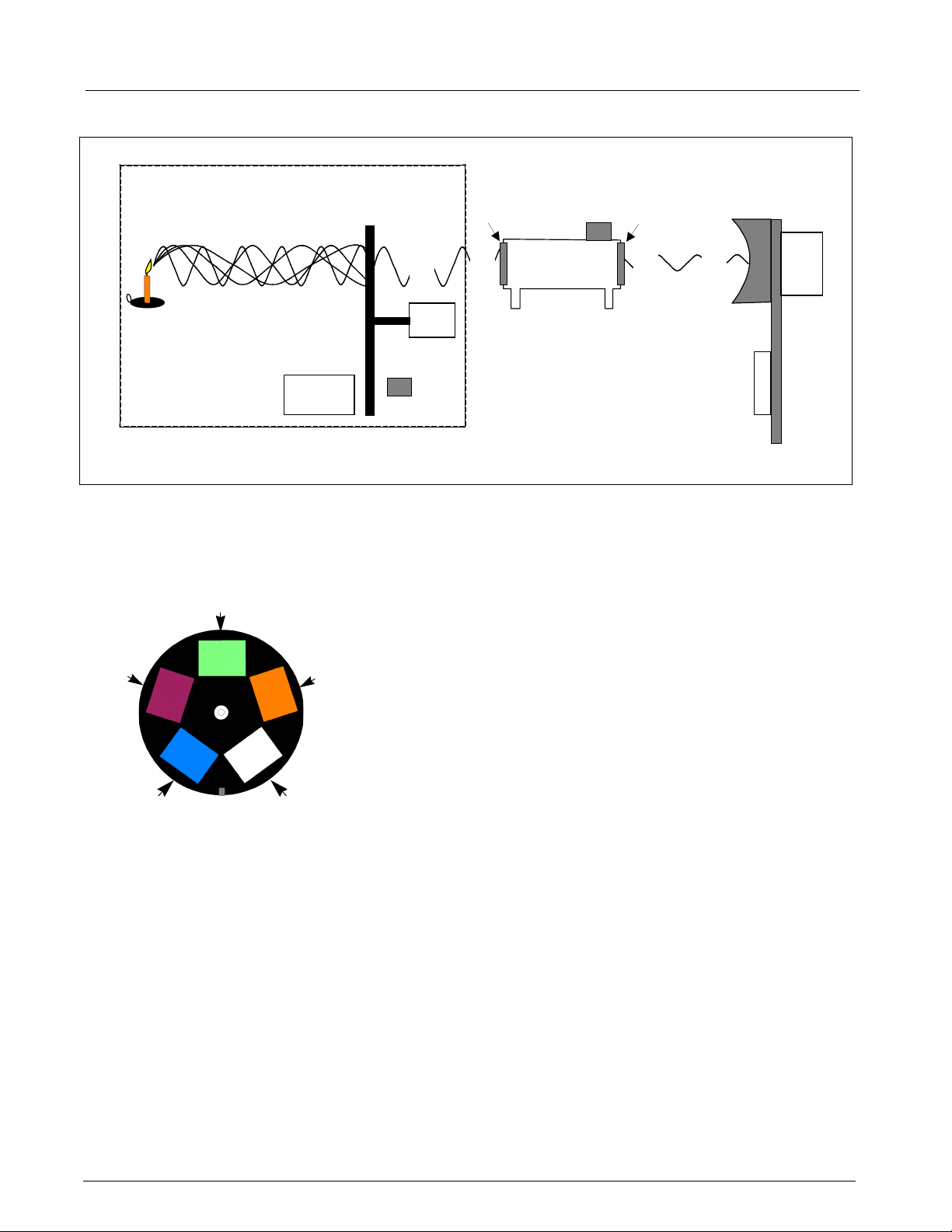
7 Agent Measurement Analyzer
The proven, known, and widely used technology of non-dispersive infrared
gas analysis is used by the AMA in the Anesthetic Gas Subsystem.Figure
2-3 on page 8 is a functional block diagram of this analyzer subsystem.
The infrared light source is constructed of tungsten powder metal which is
embedded in an Al
operating temperature of 600°C. Infrared emission from this source is
distributed as a blackbody radiator.
ceramic. This source is electrically heated to an
2O3
ASK-T876-02-7600 Siemens Medical Systems, EM-PCS Danvers 7
mgm2.sm.fm/11-00/kaupp
Page 16
MGM and MGM+ Modules Service Manual
Metal Cavity
Infrared
Detector
With TE
Cooler
NVRAM
Memory
AMA Preamp
Board Assembly
Preamp
Circuits
Infrared
Light
Source
Wideband
Light Beam
Containing
Infrared
Filter Wheel
Cavity Heater
Filter Wheel
With IR Optical
Bandpass Filters
Thermistor
Mot or
Sample Cell
Window
Gas
Input
Gas
Sample
Cel l
Thermistor
Gas
Output
Sample Cell
Window
Figure 2-3 Agent Measurement Analyzer Functional Block Diagram
The sample cell is constructed of a stainless steel tube with a reflective
inside surface which serves as a light pipe. The sample cell length has been
designed to provide an adequate absorption length to obtain the desired
signal-to-noise ratio for the weakest anticipated absorption. Sapphire serves
N2O
as the sample cell window material for the two ends of the sample cell.
The gas sample to be analyzed enters the sample cell through the gas inlet and
leaves it through the gas outlet. While in the cell, the gas sample is penetrated
Agent CO
by light from the infrared light (IR) source. This light is filtered by coated optical
2
bandpass filters mounted on the filter wheel (see illustration at left). The
attached brushless DC motor spins the filter wheel so that the appropriate filter
for each gas type (CO
, N2O, agent) comes into place one after the other. The
2
filter wheel cavity heater maintains the metal cavity at 65°C under control of a
thermistor. The wavelengths used are --
Reference Blank
Filter Wheel
•4.3µ for CO
•3.6µ for N2O
• 3.3µ for anesthetic agents
2
The thermistor attached to the sample cell wall provides a measure for the
sample cell temperature. Knowledge of sample pressure and sample
temperature is vital to accurately determine gas concentrations in the gas
sample. Sample pressure is provided by a pressure transducer housed in
the AMA but actually plumbed behind the O
Analyzer. It is therefore its
2
own gas connection.
The photoresistive lead selenide (PbSe) infrared detector, mounted on the
preamplifier board assembly, converts the IR radiation not absorbed by the
gas sample to an electrical signal. The transmittance of IR radiation is a
measure of the total number of molecules of a given gas in the sample cell.
The detector’s output signals are preamplified and consist of a pulse
stream, one pulse for each IR filter, corresponding to the fraction of this gas
type in the sample. The IR detector temperature is kept at 2°C by a thermoelectric cooler to enhance signal-to-noise ratio.
A calibration mechanism guarantees long-term stable measurements and
eliminates filter variations.
8 Siemens Medical Systems, EM-PCS, Danvers ASK-T876-02-7600
mgm2.sm.fm/11-00/kaupp
Page 17

Service Manual MGM and MGM+ Modules
Chopped
Infrared
Light
Source
Wideband
Light Beam
Containing
Infrared
Light
Chopper
Motor
Wideband
Infrared
Light
Sample Cell
Window
Gas
Input
Gas
Sample
Cell
Figure 2-4 Agent Identification Analyzer (AIDA) Functional Block Diagram
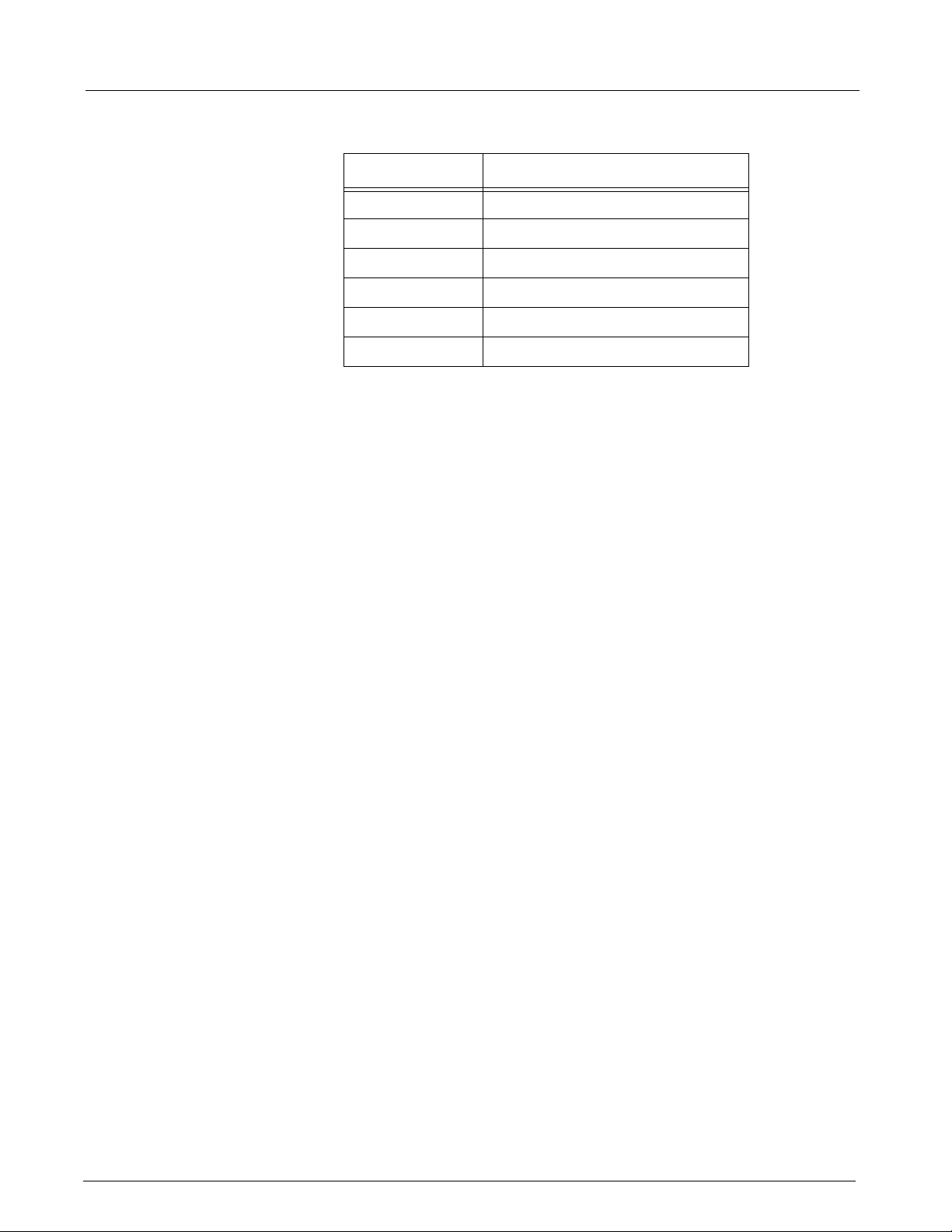
8 Agent Identification Analyzer
Gas
Output
Sample Cell
Window
Specific
IR Wavelengths
IR Optical
Bandpass
Filters
(4 of 7 illustrated)
Thermopile
Infrared
Detectors
(4 of 7 illustrated)
AIDA Preamp
Board Assembly
Thermistor
Preamp
Circuits
NVRAM
Memory
The agent identification function identifies which of the following
anesthetic agents is being used:
• one agent out of Isoflurane, Halothane, Enflurane, or
• one agent out of Isoflurane, Halothane, Sevoflurane, or
• one agent out of Isoflurane, Halothane, Desflurane.
Like the AMA, the AIDA in the Anesthetic Gas Subsystem uses the
technology of non-dispersive infrared gas analysis. Figure 2-4 shows a
functional block diagram of this analyzer subsystem.
Infrared light from the IR light source (which is identical to the AMA IR light
source) is modulated using a rotating chopper wheel driven by a stepping
motor which is speed controlled by the Electronics Subsystem.
Narrow band filtering and demodulation techniques greatly enhance the
quality of the signal generated in the infrared absorption process.
The sample cell is made of thermoplastic, and has a conical shape and nonreflective walls. The cell window material is silicon.
Seven thermopile IR detectors which do not require cooling, each output
an analog signal whose magnitude is inversely proportional to the infrared
light absorption at the corresponding frequency. These frequencies are
determined by the bandpass filters (4 of 7 illustrated in Figure 2-4)
operating in the wavelength region from 10µ to 13µ. The thermistor output
is used to compensate for the effect of IR filter temperature changes. The
analog signals are directly related to the anesthetic agent gas
concentrations in the sample cell.
The IR detector outputs are measured during both chopper wheel phases.
Measurements taken when the IR light beam is interrupted provide the
dark level reference needed by the signal processing software.
ASK-T876-02-7600 Siemens Medical Systems, EM-PCS Danvers 9
mgm2.sm.fm/11-00/kaupp
Page 18

MGM and MGM+ Modules Service Manual
These signals are amplified, filtered, and digitized by the pre-amplifier on
the pre-amplifier board assembly. The digitized waveform is then
demodulated by the electronics subsystem to obtain a transmission value
for each detector.
The following transmission data is used to obtain the gas concentration
values used by the agent identification routine.
• The seven preamplified IR detector outputs
• The thermistor output
• The Zero calibration constants
• Factory characterization constants
• Gas concentration algorithms
• Primary agent ID thresholds
• Secondary agent ID thresholds
• Primary to secondary agent ID crosstalk factors
A calibration mechanism guarantees long-term stable measurements and
eliminates filter variations.
9 Oxygen Analyzer
9.1 Paramagnetic O2
Measurement
9.2 Electrochemical O2
Measurement
10Pneumatic System
In the M
“fast” O
type sensor provides O
ULTIGAS
2
+ Module, the Paramagnetic Oxygen Transducer provides
measurement. In the M
measurement with a slower response time. Both
2
ULTIGAS
Module, the electrochemical
the paramagnetic sensor and the electrochemical cell deliver an analog
signal linearly proportional to the oxygen concentration in the sample gas.
O2 is paramagnetic, which means that a magnetic field induced in O2 will
be in the same direction as, and in greater strength than, the magnetizing
field. In the paramagnetic oxygen transducer, O
is placed in two sealed
2
spheres of a dumb-bell assembly, which is suspended on a spring device
in a symmetrical non-uniform magnetic field. The assembly assumes a
position away from the most intense part of the field.
Sample gas surrounds the dumb-bell assembly, and when the surrounding
gas contains O
by the relatively stronger paramagnetic O
, the dumb-bell spheres are pushed further out of the field
2
. The strength of the torque
2
acting on the dumb-bell is proportional to the paramagnetism of the
surrounding gas, and is converted into an analog voltage which is likewise
proportional to the oxygen concentration.
The electrochemical O2 analyzer operates like a battery. O2 in the gas
sample, in contact with an electrolyte, generates a voltage proportional to
the concentration of O
.
2
The Anesthetic Gas Subsystem includes a gas sampling system which
accurately controls the flow rate of gas through the analyzer system.
Nafion® tubing, a hygroscopic material made from Teflon and polypropylenesulfonic acid copolymer, is added to the sampling line inside the
Anesthetic Gas Subsystem to eliminate residual water. Anesthetic agents,
N
O, and CO2 are impermeable to the tubing.
2
10 Siemens Medical Systems, EM-PCS, Danvers ASK-T876-02-7600
mgm2.sm.fm/11-00/kaupp
Page 19

Service Manual MGM and MGM+ Modules
Figure 2-5 Pneumatics Block Diagram (excerpt from Figure 2-2.)
As illustrated in Figure 2-5, pneumatic solenoid valves are incorporated in
the gas stream to switch between the patient gas stream (normal
operation) and room air (during Zero calibration). The selected gas (patient
or room air) is directed to the Agent Measurement Analyzer, O
analyzer,
2
and Agent Identification Analyzer.
A servo controlled pump is attached to the exhaust of the analyzer. The
pump generates the flow through the system and pulls the gas from the
airway adapter through the analyzers to the exhaust outlet. It also delivers
the Zero calibration gas to the sample cells of the analyzer subsystems for
the periodic zero procedures, and exhausts the patient’s sample gas, zero
calibration and field calibration gases. The pump can be operated at four
different flow rates, which are hardware-adjusted during factory calibration
of the MGM. See Table 2-1.
Table 2-1 Pump Flow Rates
Flow
Type
Flow
Rate
Idle No Flow Pump switched off
Low 120
ml/min
With Paramagnetic O
analyzer
Used for analysis of
patient gas samples
High 200
ml/min
With Paramagnetic O
analyzer
Used for purging
Agent Measurement
and paramagnetic O
analyzers before and
after zero calibration
Purge 350 ml/
min
With Paramagnetic O
analyzer
Used for purging the
Agent Identification
Analyzer before and
after Zero calibration
Description
With Electrochemical O
2
analyzer
Optionally used for
analysis of patient gas
samples.
With Electrochemical O
2
analyzer
Used for normal analysis
of patient gas samples
2
With Electrochemical O2
2
analyzer
Used for purging the
Agent Measurement and
Agent Identification
Analyzers before and
after Zero calibration
2
2
ASK-T876-02-7600 Siemens Medical Systems, EM-PCS Danvers 11
mgm2.sm.fm/11-00/kaupp
Page 20

MGM and MGM+ Modules Service Manual
A flow sensor, consisting of a differential pressure transducer, a dampener,
and a flow restrictor, is used to determine, stabilize and limit the flow rate
of the sampled gas. The output from the pressure transducer is used in a
servo system to control the drive power to the pump. The dampener (a
15cc container) isolates the sample cells of the analyzer subsystems from
pulsations, enabling a smooth flow through the system. The flow rate
control logic works as hard as necessary to maintain the selected flow rate.
A partial occlusion, or an inefficient pump, result in the pump being driven
harder. A serious occlusion results in the pump being driven at or near its
maximum drive. A sense circuit is then triggered to report an occlusion.
11Self-Test
A power-up self-test is performed to validate the contents of firmware
memory (ROM), read/write memory (RAM) and non-volatile memory
(NVRAM), and to verify errorless access to these storage devices for read
and write operations.
12Calibration
In order to guarantee long-time stable measurement performance the
MGM must be enabled to cope with three types of conditions that can lead
to measurement errors:
12.1 Factory Calibration
12.2 Field Span
Calibration
• Small differences among the components of a subsystem (e.g.,
caused by limitations in manufacturing precision)
• Changes of the physical properties of some components over time
(e.g., caused by aging or pollution)
• Limitations in the compensation for certain effects (e.g., changes in
cell temperature/pressure or cross-gas interference)
Each of these conditions can be handled by an appropriate calibration
process performed either during original manufacture, as part of normal
preventive maintenance, or during normal use.
During factory calibration, the individual performance of each subsystem
unit is measured. Polynomial coefficients are then calculated from these
individual response curves and stored in the unit itself. These coefficients
are later used to compensate for possible unit-to-unit component
differences.
During field Span calibration, accurately known concentrations of each gas
of interest are introduced into the AMA and O
measured. Differences between the known and the measured values are
used to calculate the appropriate coefficients for compensation of these
differences.
Field Span calibration of the anesthetic agent, CO
typically part of preventive maintenance.
The paramagnetic O
When an electrochemical O
periodically be Span calibrated.
analyzer typically does not require Span calibration.
2
sensor is in use, the O2 channel must
2
Analyzer sample cells and
2
and N2O channels is
2
12.3 Zero Calibration
12 Siemens Medical Systems, EM-PCS, Danvers ASK-T876-02-7600
During Zero calibration, the analyzer subsystems are purged with room air
or nitrogen to eliminate any gas of interest (concentration of these gases is
“zero”). Oxygen or nitrogen are convenient “Zero calibration gases” since
they do not absorb infrared radiation in the wavelengths used by the AMA
and AIDA. Since atmospheric air is composed primarily of oxygen and
mgm2.sm.fm/11-00/kaupp
Page 21

Service Manual MGM and MGM+ Modules
nitrogen, with small amounts of water and CO2, normal room air is used
for zeroing the MGM system. Optionally, the MGM can be Zero calibrated
with 100% dry nitrogen.
Since changes of physical properties of subsystem components have the
same effect on room air measurement performance, this is used as a
reference and therefore to calculate new coefficients which help
compensate for such changes. Zero calibration of the MGM analyzer
subsystem is requested by the MGM as follows:
• after certain time intervals
• after certain changes in operation
• after certain operational failures have been detected.
The Zero calibration process measures the infrared signal strength
(transmittance) when no IR absorbing gases are in the sample cell. AMA
and AIDA field calibration software compensates for the small absorption
12.4 Storage of
Calibration Data
from atmospheric CO
With one exception, all Zero calibration data is stored in and used from
volatile RAM memory. The Zero calibration data calculated by the first
successful Zero calibration after is stored in non-volatile NVRAM memory
for use after subsequent resets.
.
2
All Span calibration data is stored in non-volatile NVRAM memory. Critical
data is replicated into a second location in both RAM memory (for
immediate use) and NVRAM memory.
Block checksums are used to confirm continued validity of NVRAM and
RAM data. Power cycling does not affect this data
Both the AMA and AIDA subsystems have their own NVRAM memory for
storing their own calibration data, enabling interchangeability of these
subsystems with system boards.
Calibration data for the oxygen analyzer is stored in AMA NVRAM memory.
12.5 Calibration of Agent
Measurement
Analyzer
12.5.1 Factory Calibration Factory calibration compensates for small differences among the following
components: pressure transducer, infrared (IR) light source, sample cell
thermistor, filter heater element, filter cavity thermistor, each of the IR
bandpass filters, IR detector, and thermo-electric cooler. Near the end of
the manufacturing process, binary gases are used to characterize each
AMA. The characterization process also analyzes individual cross-gas
interference. The last function performed during characterization is to
verify performance by sampling cocktail gases. Each unit ends up with is
own unique set of response curves, and the ability to accurately report gas
concentrations based on its individual parts and characteristics.
12.5.2 Field Span Calibration The AMA should be calibrated by trained service personnel once every 12
months using precision calibration gases. The resulting Span calibration data
is stored in NVRAM memory. The host system can replace field calibration
data with the original factory calibration data via software command.
12.5.3 Zero Calibration To maintain the highest gas concentration measurement accuracy
possible, the MGM requests that the host command Zero calibration at the
following time intervals The Zero calibration is performed automatically,
requiring no user intervention.
ASK-T876-02-7600 Siemens Medical Systems, EM-PCS Danvers 13
mgm2.sm.fm/11-00/kaupp
Page 22
MGM and MGM+ Modules Service Manual
:
Zero Calibration Time Interval
1st 8 minutes after power-up or reset
2nd 15 minutes after power-up or reset
3rd 30 minutes after power-up or reset
4th 45 minutes after power-up or reset
5th 90 minutes after power-up or reset
next 8 hours after previous calibration
12.6 Agent Identification
Analyzer
12.6.1 Factory Calibration Factory calibration compensates for small differences among the following
components: infrared (IR) light source, detector thermistor, each of the
seven IR bandpass filters, and each of the seven IR detectors. Near the end
of the manufacturing process, binary gases are used to characterize each
AIDA. The last function performed during characterization is to verify performance by sampling cocktail gases. Each Analyzer ends up with its own
unique set of response curves, and the ability to accurately measure and
identify anesthetic agents based on its individual parts and characteristics.
12.6.2 Field Span Calibration The function of the AIDA is to measure accurately very low gas
concentrations, most critically in the range of 0.0% to 0.5% where
identification thresholds are set. Since field Span calibration would not
influence the performance of the Analyzer in this very narrow range, none
is required.
12.6.3 Zero Calibration As with the AMA, regular Zero calibration is required. The Zero calibration
process is exactly the same as for the AMA, but the time intervals are
slightly different. The first Zero calibration is performed automatically
(without host involvement) 2 minutes after power-up. Other Zero calibrations are requested of the host system as described in Section 12.5.3.
12.7 Paramagnetic O2
Analyzer
12.7.1 Factory Calibration The paramagnetic O2 analyzer is calibrated with potentiometers at the 0%
and 100% point of its measurement range.
12.7.2 Field Span Calibration The paramagnetic O
calibration commands using appropriate precision calibration gases.
The resulting Span calibration data is stored in NVRAM memory. The host
can replace field calibration data with the original factory calibration data via
software command.
12.7.3 Field Zero Calibration Zero calibration of the paramagnetic O
air. This is done every time the AMA is Zero calibrated.
analyzer may be Span calibrated in the field via Span
2
analyzer is performed with room
2
12.8 Fuel Cell Type O2
Analyzer Calibration
12.8.1 Factory Calibration The fuel cell type O2 analyzer does not require “characterization” or factory
calibration. In the case where a fuel cell type O
to original equipment shipment, field Span and Zero calibration are
performed.
14 Siemens Medical Systems, EM-PCS, Danvers ASK-T876-02-7600
analyzer is installed prior
2
mgm2.sm.fm/11-00/kaupp
Page 23

Service Manual MGM and MGM+ Modules
12.8.2 Field Span and Zero
Calibration
The fuel cell type O
output is continually degrading during use. Fuel cell type O
analyzer must be periodically Span calibrated since its
2
analyzer Span
2
and Zero calibration is performed using the MGM 2-point Span calibration
command as discussed in Section 12.7.2. The resulting O
calibration data
2
is stored in NVRAM memory.
12.8.3 Field Zero Calibration Separate Zero calibration of the fuel cell type O
analyzer is not required.
2
12.9 Pneumatic System
Calibration
12.9.1 Factory Calibration The pneumatic system of the Agent Analyzer Subsystem is factory-
calibrated by performing range adjustments. A flow meter is used to adjust
the four possible flow rates in which the pump can operate. These values
are set by appropriately adjusting three potentiometers.
The specific flow rates listed below are representative of one MGM
configuration. Other configurations may use slightly different flow rates.
Flow Type Flow Rate
Idle No flow
Low 120 ml/min
High 200 ml/min.
Purge 350 ml/min.
12.9.2 Field Flow Rate Calibration Trained service personnel may perform a field calibration of the pneumatic
system. A field calibration consists of the same range adjustments done
during the factory calibration.
13Software
Figure 2-6 on page 16 shows a functional block diagram of MGM software.
Each bubble indicates a submodule of that software and represents a
functional task that is described in more detail below. Each box indicates a
hardware part controlled by the firmware. Figure 2-6 also shows that the
AIDA Control and Data Processing submodules run on its own AIDA
Electronics Subsystem while all remaining submodules are executed by
the MGM/AMA Electronics Subsystem, both shown in Figure 2-6.
13.1 AMA Data
Acquisition
The AMA Data Acquisition submodule, physically located on the AMA,
acquires IR detector output signal pulses, sample cell pressure, sample
cell temperature, filter wheel cavity temperature, and IR detector
temperature data from the AMA. Additional data acquired by the
submodule includes ambient temperature, pump flow rate, four MGM
system board voltage measurements and the output of the O
analyzer.
2
These analog signals are digitized by an A-D converter in the MGM/AMA
Electronics Subassembly. The submodule stores this raw data in shared
RAM memory so that the AMA Signal Processing and the Control
submodules can access and further process them.
ASK-T876-02-7600 Siemens Medical Systems, EM-PCS Danvers 15
mgm2.sm.fm/11-00/kaupp
Page 24

MGM and MGM+ Modules Service Manual
Figure 2-6 Software Functional Block Diagram
13.2 AMA Signal
Processing
The AMA Data Acquisition and Control submodules send control signals to
the AMA to control its IR source, TE cooler temperature, filter wheel motor
speed, and filter wheel heater temperature.
Additional data acquired by the submodule includes ambient temperature,
pump flow rate, four MGM system board voltage measurements and the
output of the O
These analog signals are digitized by an A-D converter in the MGM/AMA
Electronics Subassembly. The submodule stores this raw data in shared
RAM memory so that the AMA Signal Processing and the Control
submodules can access and further process them.
The AMA Data Acquisition and Control submodules send control signals to
the AMA to control its IR source, TE cooler temperature, filter wheel motor
speed, and filter wheel heater temperature.
The Data Acquisition submodule checks the digitized data against A-D
converter boundary conditions and issues an A-D limit error to the MGM/
AMA Control submodule if necessary.
The AMA Signal Processing submodule reads the AMA IR detector output
data from RAM memory, takes an average of four samples and normalizes
this average by multiplying the zero constant offset determined during the
last Zero calibration of the AMA. This zero constant is read from the AMA
RAM memory. The normalized data is stored in RAM memory from where
it is read and further processed by the AMA Gas Concentration Algorithms
submodule.
analyzer.
2
16 Siemens Medical Systems, EM-PCS, Danvers ASK-T876-02-7600
mgm2.sm.fm/11-00/kaupp
Page 25

Service Manual MGM and MGM+ Modules
The AMA Signal Processing submodule then checks the normalized data
against an allowable input range stored in NVRAM during factory
calibration. In case the normalized data is out of that range, an overrange or
underrange error is flagged to the MGM/AMA Control submodule.
During Zero calibration of the AMA, the AMA Signal processing submodule
is triggered by the MGM/AMA Control submodule to compute a new zero
constant based on the current average. This average is interpreted as “zero
gas concentration.” The AMA Signal Processing then stores that new zero
constant offset into AMA NVRAM and into AMA RAM memory.
13.3 AMA Compensation
The AMA Gas Concentration Algorithms submodule reads the normalized
sample data from RAM memory and corrects for sample cell pressure and
sample cell temperature.
Since the spectra of the various measured gases partly overlap, the AMA
Gas Concentration Algorithms submodule performs necessary corrections
to compensate for the effects of this overlapping (called “cross-channel.
This compensation is based on the characteristics of each gas spectrum as
they were stored into NVRAM memory during factory calibration.
The submodule then applies the field calibration factor. The field calibration
factor is read from AMA NVRAM. The resulting gas concentration data is
stored in RAM memory for further processing.
The submodule checks the compensated data for mathematical errors (as
recognized by the floating point part of the CPU, e.g., a number going to
infinity or out of the floating point range), against the allowable absorption
data range (as stored in NVRAM during factory calibration), and against the
minimum and maximum reporting range limits (stored in ROM memory). In
case of wrong or out-of-range data, errors are issued to the MGM/AMA
Control submodule.
During field Span calibration of the AMA, the AMA Gas Concentration
Algorithms submodule is triggered by the MGM/AMA Control submodule
to compute new field Span calibration factors based on current gas concentration data. The AMA Gas Concentration Algorithms submodule then
stores the new field Span calibration factors in AMA NVRAM memory.
13.4 Patient Data
Derivation
13.5 Host System
Communications
ASK-T876-02-7600 Siemens Medical Systems, EM-PCS Danvers 17
mgm2.sm.fm/11-00/kaupp
The Patient Data Algorithms submodule reads the compensated sample
data (wave samples) from RAM memory and derives the following
numerical values from them:
•Breath Rate
• Inspired values for CO
O
2
• Expired end-tidal values for CO2, N2O, and anesthetic agent; Expired
end-tidal value for O
Breath rate is calculated based on the time between two breaths. The
inspired and expired end-tidal values are calculated from the wave samples
which were valid at the beginning and end of a breathing cycle. Patient data
is stored in RAM memory from where it can be read and transmitted to the
host system. If the Patient Data Algorithms submodule cannot derive
numerics from the wave sample data, e.g., if the patient stops breathing,
it issues a status message to the MGM/AMA Control submodule.
The Host System Communications submodule reads the wave samples,
patient data numerics and status/error information from RAM memory and
transmits them to the host.
, N2O, and anesthetic agent; Inspired value for
2
2
Page 26

MGM and MGM+ Modules Service Manual
The submodule receives commands from the host (e.g., requests to Zero
calibrate, requests to field Span calibrate, requests to format data in certain
units) and executes them either by itself or by passing them on the MGM/
AMA Control submodule or, via AMA-AIDA interprocessor communications to the AIDA Control submodule. Thus, the Host System
Communications submodule is the only one that communicates directly
with the host system.
13.6 Anesthetic Gas
Subsystem /
Host System
Communications
13.7 AIDA
Communication
Communications between the Anesthetic Gas Subsystem and the host
system consists of communications between the Host System
Communication submodule and the host’s communications software over
the external RS-232 interface of the MGM. All messages from and to the
MGM include a checksum to assure the detection of communication
interferences. Moreover, a message length is defined for the commands
sent to the MGM and their corresponding responses to enable a check on
the format of the received message.
The AMA-AIDA Interprocessor Communications submodule in the MGM/
AMA Electronics subsystem serves as the communication link between
the MGM/AMA Electronics Subsystem and the AIDA electronics
subsystem. lt communicates directly with its counterpart, the AIDA-AMA
Interprocessor Communications submodule in the AIDA Electronics
Subsystem, using the same communications protocol that the Host
System Communications submodule uses to communicate with the host.
It is controlled by the MGM/AMA Control submodule (e.g., to synchronize
Zero calibration of both the AMA and the AIDA). It exchanges status
information with the MGM/AMA Control submodule and the Host System
Communications submodule.
The AIDA-AMA Interprocessor Communications submodule serves as the
communication link between the AIDA electronics subsystem and the
MGM/AMA electronics subsystem. It communicates directly with its
counterpart, the AMA-AIDA Interprocessor Communications submodule,
using the same communications protocol that the Host System
Communications submodule uses to communicate with the host.
It exchanges status/control information with the AIDA Control submodule
and receives data from the AIDA Agent Identification submodule via RAM
memory and passes them on to the AMA-AIDA Interprocessor
Communications submodule for further transmission to the Host System
Communications submodule.
13.8 MGM/AMA Control
18 Siemens Medical Systems, EM-PCS, Danvers ASK-T876-02-7600
The MGM/AMA Control submodule performs a variety of control tasks:
It receives commands, e.g., requests to Zero or field Span calibrate, from
the Host System Communications submodule and triggers the AMA Data
Acquisition, AMA Signal Processing, AMA Gas Concentration Algorithms,
and Patient Data Algorithms submodules accordingly.
It receives error messages from the AMA Data Acquisition, AMA Signal
Processing, AMA Gas Concentration Algorithms, and Patient Data
Algorithms submodules, and passes them on with other status information
to the Host System Communications submodule.
The MGM/AMA Control submodule is also involved in controlling the
pump: The pump control hardware reads the current gas flow rate from the
flow sensor and controls the pump to guarantee a stable gas flow through
the system. The flow rate is monitored by the MGM/AMA Control
mgm2.sm.fm/11-00/kaupp
Page 27

Service Manual MGM and MGM+ Modules
submodule. Also, the pump control hardware sends status messages to
the Host System Communications submodule, reporting occlusion
(detected by pump running at upper limit).
During Zero calibration, the MGM/AMA Control submodule is triggered by
the Host System Communications submodule to send the appropriate
control signals to the pump and solenoid valves. At the end of the Zero
calibration, it switches the pump and valves back to normal operation.
13.9 AIDA Data
Acquisition
13.10 AIDA Signal
Processing
The AIDA Data Acquisition submodule, physically located on the AIDA,
acquires output data from the AIDA, consisting of signal pulses from the
thermopile infrared (IR) detectors and detector temperature. These signals
are digitized by an A-D converter in the AIDA electronics subsystem. The
Data Acquisition submodule stores this data in AIDA RAM memory so that
the AIDA Signal Processing submodule can access and further process it.
The Data Acquisition submodule also sends control signals back to the
AIDA to control its light chopper motor speed and thermopile detector
temperature. These control signals are computed by the AIDA Control
submodule and written to another area of RAM memory so that it can be
read by the AIDA Data Acquisition submodule.
Finally, the AIDA Data acquisition submodule checks the raw data against
the A-D converter boundary conditions and issues an A-D limit error to the
AIDA Control submodule, if necessary.
The AIDA Signal Processing submodule reads the AIDA sample data from
RAM memory, takes a moving average of 22 samples and normalizes this
average by adding the Zero constant offset determined during the last
AIDA Zero calibration. This Zero constant is read from the AIDA RAM
memory. The normalized data is stored in RAM memory from where it is
read and further processed by the AIDA Agent Identification submodule.
The AIDA Signal Processing submodule then checks the normalized data
against an allowable input range stored in NVRAM memory during factory
calibration. In case the normalized data is out of that range, an overrange or
underrange error is flagged to the AIDA Control submodule.
During AIDA Zero calibration, the AIDA Signal Processing submodule is
triggered by the AIDA Control submodule to compute a new Zero constant
based on the current average. This average is interpreted as “zero gas
concentration.” The AIDA Signal Processing submodule then stores that
new Zero constant offset into AIDA RAM memory.
13.11 AIDA Agent
Identification
ASK-T876-02-7600 Siemens Medical Systems, EM-PCS Danvers 19
mgm2.sm.fm/11-00/kaupp
The AIDA Agent Identification submodule reads the averaged gas
concentration data supplied by the seven thermopile IR detectors and
identifies the most dominant agent contained in the gas sample.
The relationship of gas concentration and absorption is expressed by quite
elaborate non-linear equations, with the number of experimentally
determined parameters varying with the particular gas species and IR filter.
Since AIDA agent identification is able to simultaneously detect the
presence of as many as all five possible agents, an equation is set up for
each IR channel that expresses the transmitted signal as a function of the
absorption by all five agents, where the only unknowns are the desired gas
concentrations. These five gas concentrations are then determined
iteratively by solving the resulting set of seven non-linear equations.
The final computed gas concentrations for each set of gas samples are
then tested against the thresholds for primary and secondary agent
Page 28

MGM and MGM+ Modules Service Manual
identification. This is achieved by first identifying all agents whose gas
concentrations exceed their corresponding threshold for primary agent
detection. If there is only one such agent, it is flagged as being the primary
agent. If there is more than one agent, the agent with the highest
concentration is flagged as being the primary agent. In this case, the
concentrations of the remaining agents are tested to determine if they
exceed their corresponding thresholds for secondary agent, (or
contamination), thresholds. Any agents for which this criterion is true are
flagged as secondary agents. If a secondary agent has been identified, this
is flagged to the AIDA Control submodule.
If any of the calculated agent concentrations are more negative than the
negative of the corresponding agent thresholds, it is assumed that a gas is
present for which the AIDA agent identification has not been calibrated. In
this case nothing can be said about the composition of the mixture other
than that it is unknown.
If a set of gas samples were to be detected for which no solution existed,
the algorithm will detect this quickly and terminate the iterative process
and return a set of zero gas concentrations, and flag an error. The AIDA
Agent Identification submodule stores its results in RAM memory where
they can be read by the AIDA-AMA Interprocessor Communications
submodule to be passed on to the host via the AIDA/AMA Interprocessor
Communications and Host System Communications submodules.
13.12 AIDA Control
The AIDA Control submodule performs various control tasks.
It receives commands, e.g., a request to Zero calibrate, from the Host
System Communications submodule via the AMA-AIDA Interprocessor
Communications and the AIDA-AMA Interprocessor Communications
submodules and triggers the AIDA Data Acquisition, AIDA Signal
Processing, and AIDA Agent Identification submodules accordingly.
It also receives error/status messages from the AIDA Data Acquisition,
AIDA Signal Processing, and AIDA Agent Identification submodules and
passes them on with other status information to the Host System
Communications submodule (again via the AMA-AIDA Interprocessor
Communications and AIDA-AMA Interprocessor Communications
submodules.
20 Siemens Medical Systems, EM-PCS, Danvers ASK-T876-02-7600
mgm2.sm.fm/11-00/kaupp
Page 29

Chapter 3 Removing / Installing Parts
1Introduction
Warning
All parts of a MultiGas/+ module that either directly or indirectly
come in contact with the patient’s airway (such as all internal
and external tubing, water trap and water trap manifold, and
filters) may be contaminated. Handle according to the hospital’s
procedures and guidelines for handling infectious substances.
Also, see Disease Prevention in this Service Manual.
Caution
3
Open MultiGas/+ module only in a static-protected
environment. Observe standard precautions for protecting the
equipment from static electricity.
1.1 Opening Module
To access internal components and subassemblies in the MultiGas/+
module, do the following:
1. Turn off power to MGM module, and also unplug AC line cord.
2. Remove and save four Phillips-head screws located near back on
bottom of outer case.
3. Slide entire internal subassembly out of case, from front of module.
The following procedures describe removing and replacing parts listed
below.
• Pneumatics Subssemblies (MGM+)
• Pneumatics Subasssemblies (MGM)
• Nafion® or other Tubing
• Room Air Filter
•Pump
• Pump filter
•AMA Analyzer Head
•AMA Sample Cell
•AIDA Analyzer Head
• MGM System Board
•Fast O
•CAN PC Board
• Power Supply
• Solenoid #1 & #3
• Solenoid #2
ASK-T876-02-7600 Siemens Medical Systems, EM-PCS Danvers 21
mgm2.sm.fm/11-00/kaupp
Sensor Assembly
2
Page 30

MGM and MGM+ Modules Service Manual
g
j
Filter
;
l
V
h
Figure 3-1 Pump and Pneumatic Subassemblies in MGM+
2MGM+
2.1 Pneumatic Tubing
Subassemblies
k
S2
P
Red Band
S3
B
A
a
All pneumatic tubing subassemblies in the MGM+ Module are replaced as
complete subassemblies. Refer to Figure 3-1.
f
S1
s
AIDA
(4750)
d
AMA
(4710)
Orientation Red Band
2.1.1 Removing Pneumatic
Subassemblies
2.1.2 Installing Pneumatic
Subassemblies
1. Open Module. See “Introduction” on page 21.
2. Disconnect and discard tubing between input filter holder and S1(a in
Figure 3-1).
3. Disconnect and discard tubing subassembly from water input (center
port) on bulkhead at AIDA-head (4750) (s in Figure 3-1), vacuum input
of pump (j in Figure 3-1), and input filter holder (k in Figure 3-1).
4. Disconnect and discard tubing and filter between AMA-head (4710)
and S1(d in Figure 3-1).
5. Disconnect and discard remaining tubing from S1 to S2 (f in Figure 3-1)
and room air inlet filter (including filter). (Do NOT remove inlet tubing
(g in Figure 3-1) from back of module to filter!)
6. Do either a or b.
a If replacing pump, go to Section 4.1.
b If replacing only pneumatic tubing, continue.
Note: Carefully inserting the tip of long-nose pliers into the end of
polyurethane ether tubing to partially stretch it, can significantly aid in
connecting tubing. Be careful, however, not to overstretch the
material. Doing so could permanently damage the tubing, resulting in
intermittent pneumatic leaks and performance problems.
1. Install tubing assembly 450334-001 between S1 and S2 (f in Figure
3-1), and insert filter into inlet hose from back of unit (g in Figure 3-1).
22 Siemens Medical Systems, EM-PCS, Danvers ASK-T876-02-7600
mgm2.sm.fm/11-00/kaupp
Page 31

Service Manual MGM and MGM+ Modules
f
s
A
B
g
;
l
h
Figure 3-2 Pump and Pneumatic Subassemblies in MGM (Slo-O2)
j
RED DOT
k
S1
S3
B
A
2. Install tubing assembly 450321-001 connecting AMA-head (4710) and
S1(d in Figure 3-1).
AIDA
(4750)
a
AMA
(4710)
d
ORIENTATION RED DOT
3 MGM (Slo-O2)
3.1 Replacing Pneumatic
Subassemblies
3.1.1 Removing Pneumatic
Tubing
3. Connect end of tubing assembly 450349-000 (s in Figure 3-1) from
piece to center port on AIDA-head (4750) and then secure restrictor
(j in Figure 3-1) in holder.
4. Connect tubing from
vacuum input on pump (h in Figure 3-1).
5. Connect remaining end of tubing subassembly 450349-000 into water
line on input filter holder (k in Figure 3-1).
6. Do either a or b.
a If replacing pump, go to Section 4.2.
b If only replacing pneumatic tubing, continue.
7. Connect tubing subassembly 450323-001 between S1 and input line
filter holder (a in Figure 3-1).
8. Check all connections, reinstall cover (See “Opening Module” on
page 21.), and functionally verify proper operation of MGM+ Module.
Refer to procedures in “Functional Verification” on page 45.
Refer to Figure 3-2.
1. Open Module. See “Introduction” on page 21.
2. Disconnect and discard tubing from input filter to S1(k in Figure 3-2).
T
-piece of tubing subassembly 450349-000 into
T
-
3. Disconnect and discard tubing from AMA-head (4710) to AIDA-head
(4750) (a in Figure 3-2).
ASK-T876-02-7600 Siemens Medical Systems, EM-PCS Danvers 23
mgm2.sm.fm/11-00/kaupp
Page 32

MGM and MGM+ Modules Service Manual
4. Disconnect and discard tubing and filter from S1 to room air input line
(s in Figure 3-2).
5. Disconnect and discard remaining tubing from S1 to AMA-head (4710)
(d in Figure 3-2).
6. Disconnect entire subassembly, including restrictor (f in Figure 3-2),
from O2 cell (g in Figure 3-2), pump input (h in Figure 3-2), and
connection to water input filter holder (on bracket above pump) (j in
Figure 3-2).
7. Do either a or b.
a If replacing pump, go to Section 4.1.
b If replacing only pneumatic tubing, continue.
3.1.2 Installing Pneumatic Tubing 1. Install tubing subassembly 450328-001between AMA-head (4710) and
AIDA-head (4750) (a in Figure 3-2).
2. Install tubing subassembly 450321-001 between AMA-head (4710)
and S1(d in Figure 3-2).
3. Connect end of tubing subassembly 450353-000 to water input filter
holder (on bracket above pump) (j in Figure 3-2), and then route
restrictor (f in Figure 3-2) through holder.
4Replacing Pump
4.1 Removing Pump
4. Connect tubing from
pump input (h in Figure 3-2).
5. Connect remaining end of tubing subassembly 450353-000 to O2 cell
input (g in Figure 3-2).
6. Connect tubing and filter subassembly 450284-002 (s in Figure 3-2)
between S1 and room air input line.
7. Connect tubing subassembly 450323-001 between S1 and sample
input line filter holder (k in Figure 3-2).
8. Do either a or b.
a If replacing pump, go to Section 4.2.
b If only replacing pneumatic tubing, continue.
9. Check all connections, reinstall cover (See “Opening Module” on
page 21.), and functionally verify proper operation of MGM Module.
Refer to procedures in “Functional Verification” on page 45.
Use the following procedure to replace pump.
Note: Pump replacement requires that all pneumatic subassemblies
referenced in Section 2.1 also be replaced.
1. After completing steps of Section 2.1.1 (if MGM+) or Section 3.1.1 (if
MGM), disconnect nafion lines (gas and water) (l in Figure 3-1 on
page 22 or Figure 3-2 on page 23) from bracket above pump.
T
-piece on tubing subassembly 450353-000 to
Note: Observe that gas input line is unmarked and water input line is
marked with a red band.
2. Remove and save Phillips-head screw from filter bracket above pump.
3. Disconnect tubing (; in Figure 3-1 on page 22 or Figure 3-2 on page
23) from pump filter port.
4. Loosen wire guides on side of AMA.
24 Siemens Medical Systems, EM-PCS, Danvers ASK-T876-02-7600
mgm2.sm.fm/11-00/kaupp
Page 33

Service Manual MGM and MGM+ Modules
5. Disconnect pump wires from system board connector, J8. (See
Figure 3-3 on page 27.)
6. Cut and remove any wire ties holding pump wire assemblies in place,
and remove wire harness.
Note: Carefully note location(s) of wire ties and routing of pump
wires.
7. Remove and save two screws holding pump assembly in place, and
remove pump and attached pneumatic subassembly.
8. Install pneumatic subassemblies before installing pump. Refer to
Section 2.1.2 for an MGM+ and to Section 3.1.2 for an MGM (Slo-O2).
4.2 Installing Pump
1. Secure new pump assembly in base of unit with two mounting
screws removed in step 7 of Section 4.1 above.
2. Reinstall tubing (; in Figure 3-1 on page 22 or Figure 3-2 on page 23)
on pump filter port.
3. Route pump wires and secure wires to solenoid harness using wire
ties, as noted in step 6 of Section 4.1 above.
4. Reinstall filter bracket and reconnect Nafion lines. Be sure that line
with red band is connected as illustrated in Figure 3-1 on page 22 or
Figure 3-2 on page 23.
5. Go to Section 2.1.2 to complete installation of pneumatic tubing
subassemblies in MGM+ Module or to Section 3.1.2 to complete
installation of pneumatic tubing subassemblies in MGM Module.
5 Pump Filter Removal/Replacement Procedure
5.1 Removal
5.2 Replacement
1. Open Module. See “Introduction” on page 21.
2. Disconnect tubing from Pump Filter.
3. Remove Pump Filter from holding clamp.
1. Reverse steps in Section 5.1 to install replacement Pump Filter.
2. Functionally verify proper operation of the MGM. Refer to procedures
in “Functional Verification” on page 45.
6 Nafion® or other Tubing Removal/Replacement Procedure
6.1 Removal
6.2 Replacement
ASK-T876-02-7600 Siemens Medical Systems, EM-PCS Danvers 25
mgm2.sm.fm/11-00/kaupp
1. Open Module. See “Introduction” on page 21.
2. Disconnect and remove defective tubing. If another part must be
removed to access tubing, follow procedure for that part also.
1. Install new tubing in same position, using same type and length of
tubing as was originally installed.
2. Reverse procedure of Section 1.1 on page 21 to replace top cover.
3. Functionally verify proper operation of the MGM. Refer to procedures
in “Functional Verification” on page 45.
Page 34

MGM and MGM+ Modules Service Manual
7 Room Air Filter Removal/Replacement Procedure
7.1 Removal
7.2 Replacement
1. Open Module. See “Introduction” on page 21.
2. Unscrew room air filter bracket from pneumatics chassis.
3. Disconnect tubing going to Room Air Filter.
4. Remove piece of tubing that holds Room Air Filter onto bracket.
5. Extract room air filter out of hole in bracket.
1. Put replacement Filter through hole in bracket and secure with short
piece of tubing.
2. Connect tubing going to Room Air Filter.
3. Screw room air filter bracket back on to pneumatics chassis.
4. Reverse procedure of Section 1.1 on page 21 to replace top cover.
5. Functionally verify proper operation of the MGM. Refer to procedures
in “Functional Verification” on page 45.
8 AMA Analyzer Head Removal/Replacement Procedure
8.1 Removal
1. Open Module. See “Introduction” on page 21.
2. Perform NVRAM Transfer Procedure (refer to “NVRAM Transfer
Procedure” on page 31).
Note: This is necessary when an AMA Analyzer Head is replaced
(and the AMA Analyzer Head is mounted onto the Pneumatics
Assembly). If the same AMA Analyzer Head is to be reinstalled, go on
to step 4.
3. Remove 1 ribbon cable and 3 tubes connected to AMA Analyzer Head.
4. Remove 4 screws that hold Pneumatics Assembly to bottom chassis.
5. Lift (do NOT need to remove all cables and tubing) Pneumatics
Assembly.
6. Remove 3 mounting screws holding AMA Analyzer Head to
Pneumatics Assembly.
8.2 Replacement
1. Reverse steps in Section 8.1 to install replacement Analyzer Head.
2. Functionally verify proper operation of the MGM. Refer to procedures
in “Functional Verification” on page 45.
9 AMA Sample Cell Removal/Replacement Procedure
9.1 Removal
1. Open Module. See “Introduction” on page 21.
2. Remove 3 tubes connected to AMA Sample Cell.
3. Remove 4 screws that hold Pneumatics Assembly to bottom chassis.
4. Lift (do NOT need to remove all cables and tubing) Pneumatics
Assembly.
5. Remove 4 mounting screws holding AMA Sample Cell into AMA
Analyzer Head.
6. Gently pull and slide Sample Cell out of AMA Analyzer Head.
26 Siemens Medical Systems, EM-PCS, Danvers ASK-T876-02-7600
mgm2.sm.fm/11-00/kaupp
Page 35

Service Manual MGM and MGM+ Modules
10IRQ
1
2
Serial #
3
VHP
Pump SOL2
Fan
SOL1
Q4 VHP
+5V
Figure 3-3 System PC Board
9.2 Replacement
1. Reverse steps in Section 9.1 to install replacement AMA Sample Cell.
2. Functionally verify proper operation of the MGM. Refer to procedures
in Functional Verification.
10Agent ID Analyzer Removal/Replacement Procedure
10.1 Removal
10.2 Replacement
1. Open Module. See “Introduction” on page 21.
2. Remove 3 tubes connected to Agent ID Analyzer’s Sample Cell.
3. Remove 4 screws that hold Pneumatics Assembly to bottom chassis.
4. Remove 4 screws that hold Agent ID Analyzer to Pneumatics
Assembly.
1. Reverse steps in Section 10.1 to install replacement Agent ID
Analyzer.
2. Functionally verify proper operation of the MGM. Refer to procedures
in “Functional Verification” on page 45.
11MGM System Board Removal/Replacement Procedure
11.1 Removal
ASK-T876-02-7600 Siemens Medical Systems, EM-PCS Danvers 27
mgm2.sm.fm/11-00/kaupp
1. Open Module. See “Introduction” on page 21.
2. Disconnect all cable connectors and tubing connected to MGM
System Board.
3. Remove mounting screws that hold MGM System Board to chassis.
Page 36

MGM and MGM+ Modules Service Manual
11.2 Replacement
1. Reverse steps in Section 11.1 to install MGM System Board.
2. Functionally verify proper operation of the MGM. Refer to procedures
in “Functional Verification” on page 45.
12Fast O2 Sensor Assembly Removal/Replacement Procedure
Note: The O2 Sensor comes with its own control board attached.
The sensor module and board are calibrated as one unit and must
stay together.
12.1 Removal
1. Open Module. See “Introduction” on page 21.
aaaa
ssss
Figure 3-4 MGM Module Rear View
ssss
2. Remove and save knurled screws (a in Figure 3-4) that secure filter
cover to rear panel, and remove cover and filter.
3. Note routing of fan cable so that it can be properly routed during
reassembly, and unplug cable from Fan1 connector on System Board.
4. Remove and save six screws (s in Figure 3-4) that secure rear panel
subassembly to MGM main chassis.
aaaa
ssss
Figure 3-5 Pneumatic Tubing Disconnection Points
5. Disconnect tubing connecting patient sample gas outlet port to pulse
dampener at pulse dampener (a in Figure 3-5).
6. Disconnect tubing connecting zero gas inlet port to zero gas dust filter
at dust filter (s in Figure 3-5, shown partially obstructed).
28 Siemens Medical Systems, EM-PCS, Danvers ASK-T876-02-7600
mgm2.sm.fm/11-00/kaupp
Page 37

Service Manual MGM and MGM+ Modules
7. Carefully cut and remove nylon tie wrap that secures four AC wires to
AC line fuse holders. Be sure to reinstall replacement tie wrap when
reassembling module.
8. Note polarity so that wires can be properly reinstalled, and unplug two
AC cable wires from AC line fuse holders.
d
f
g
h
s
j
a
Figure 3-6 Rear Panel Subassembly
9. Unplug 26 conductor flat cable from O
10. Note scheme for connecting tubing to O
be properly reconnected to replacement sensor) and disconnect
tubing from sensor (s in Figure 3-6).
11. Slightly spread rear sides of main chassis (d in Figure 3-6) while
pulling rear panel towards rear.
sensor board (a in Figure 3-6).
2
sensor (so that tubing can
2
Note: The Rear Panel Subassembly is now virtually free and can be
12.2 Replacement
moved to provide easy access to the O
12. Remove screws (f in Figure 3-6) from clamp (g in Figure 3-6) holding
O
Sensor to bracket on chassis.
2
13. Remove O
from Rear Panel Subassembly.
Note: The sensor PCB snaps into its plastic holder. Spread the two
latches while lifting up on the board to remove it.
1. Reverse steps in Section 12.1 to install new O2 Sensor Assembly.
2. Functionally verify proper operation of the MGM. Refer to procedures
in “Functional Verification” on page 45.
Sensor (h in Figure 3-6) and Sensor PCB (j in Figure 3-6)
2
Sensor and sensor PCB.
2
13CAN PC Board Removal/Replacement Procedure
13.1 Removal
ASK-T876-02-7600 Siemens Medical Systems, EM-PCS Danvers 29
mgm2.sm.fm/11-00/kaupp
1. Open Module. See “Introduction” on page 21.
2. Remove the filter shroud and filter from the back panel.
3. Remove six screws securing back panel to chasssis.
4. Disconnect CAN board ribbon cables from J14 and J22 on the MGM
System Board.
Page 38

MGM and MGM+ Modules Service Manual
5. Remove hex screws securing RS-232 connector to rear panel (see
Figure 1-1 on page 1).
6. Separate back panel from chassis.
7. Remove two screws securing CAN board to rear panel. Refer to
Figure B-3 or Figure B-4.
8. Remove CAN PC Board.
13.2 Replacement
1. Reverse steps in Section 13.1 to install replacement board.
2. Functionally verify proper operation of the MGM. Refer to procedures
in Functional Verification.
14Power Supply Removal/Replacement Procedure
14.1 Removal
14.2 Replacement
1. Open Module. See “Introduction” on page 21.
2. Unplug power cable connector from power supply PC Board.
3. Remove 4 mounting screws holding Power Supply to chassis.
1. Reverse steps in Section 14.1 to install Power Supply.
2. Verify power supply voltages at test points on MGM System Board
(refer to Table 5-9 in Troubleshooting).
3. Reverse procedure of Section 1.1 on page 21 to replace top cover.
4. Functionally verify proper operation of the MGM. Refer to procedures
in “Functional Verification” on page 45.
15Solenoid #1 & #3 Removal/Replacement Procedure
15.1 Removal
1. Open Module. See “Introduction” on page 21.
2. Remove Solenoid #1 & #3 cable connector located at MGM System
Board (see Figure 3-3 on page 27), and free wires of cable from cable
clamps.
3. Remove tubing attached to Solenoid #1 & #3.
4. Remove 4 screws holding Solenoid #1 & #3 to Pneumatics Assembly.
15.2 Replacement
1. Reverse steps in Section 15.1 to install replacement Solenoid #1 & #3.
2. Functionally verify proper operation of the MGM. Refer to procedures
in Functional Verification.
16Solenoid #2 Removal/Replacement Procedure
16.1 Removal
16.2 Replacement
30 Siemens Medical Systems, EM-PCS, Danvers ASK-T876-02-7600
1. Open Module. See “Introduction” on page 21.
2. Unplug Solenoid #2 power cable connector from MGM System Board
(see Figure 3-3 on page 27), and free cable wires from cable clamps.
3. Remove screw holding Solenoid #2 bracket.
4. Remove tubing from ports on Solenoid #2.
5. Remove 2 screws holding Solenoid #2 to its' bracket.
1. Reverse steps in Section 16.1 to install replacement Solenoid #2.
2. Functionally verify proper operation of the MGM. Refer to procedures
in “Functional Verification” on page 45.
mgm2.sm.fm/11-00/kaupp
Page 39

Service Manual MGM and MGM+ Modules
17NVRAM Transfer Procedure
17.1 Introduction
17.2 Equipment required
17.3 NVRAM Transfer
procedure
When replacing AMA analyzer heads, essential system information (such
as flow rate limits, system ID, etc.) stored in the NVRAM of the old head
must be transferred to the replacement head.
Note: The NVRAM of a faulty head can still be read (and transferred
to a new head), except in the case of a NVRAM failure.
The purpose of the NVRAM Transfer board (NTB) is to transfer the information of a non-operational analyzer head to a replacement head in the field.
The following equipment is required:
• Replacement AMA analyzer head
• NVRAM Transfer board (NTB)
• Hand tools (screwdriver, etc.) for removal and installation of an
analyzer head. (Refer to Section 8 on page 26, AMA Analyzer Head
Removal/Replacement Procedure.)
1. Open Module. See “Introduction” on page 21.
2. Connect 40-pin cable of NTB into 40-pin connector of new
replacement analyzer head.
3. Connect 10-pin cable of NTB into top cover connector (J6) on MGM
System Board.
4. Power MGM on, and observe LED on NTB. See Notes on next page.
Note: For about the first five seconds, the LED on the NTB appears
amber. Whenever the LED appears amber, the NTB is processing
information and the operator is to stand by until the LED changes
color again. During the first five seconds, the NVRAMs of both the
old and the new analyzer heads are being read and checked. If the
LED changes to a solid green color, the NVRAM transfer process can
begin. Go to step 5 if the LED is green.
If either NVRAM cannot be read, it may take up to one minute before
LED changes color. Identify error condition as either a or b.
a) If the LED changes to a solid red color, a problem reading the old
analyzer head has occurred.
a.1 Turn OFF power and verify all connections.
a.2 Make sure ribbon cables are not broken and are fully seated.
a.3 Try to repeat the process, starting at step 4.
If the LED is still on red, turn power off and proceed with installation
of the new analyzer head regardless. The NVRAM transfer is not
possible, but the replacement head has default information for pump
hours and a serial number. However, before installing the new
analyzer head, you need to verify that the new head is indeed
functional. Replace the old analyzer head with the new one and repeat
the NVRAM transfer procedure starting at step a.1. If the LED begins
blinking alternately green and red, the head is functional and you can
continue with the installation of the new head. If the LED is solid red,
however, either the new analyzer head and/or the cable from the head
to the MGM System Board is defective. In this case, you will need to
replace the head, the cable, or both.
ASK-T876-02-7600 Siemens Medical Systems, EM-PCS Danvers 31
mgm2.sm.fm/11-00/kaupp
Page 40

MGM and MGM+ Modules Service Manual
Note: When installing a new analyzer head and using the
default NVRAM data, a flow rate calibration MUST be executed because no flow rates will be transferred. If no flow
rate calibration is performed, a problem with the pneumatic
system will be flagged during module operation. (Note that
in addition to conditions requiring potentiometer adjustment,
an unsuccessful NVRAM transfer procedure is another condition which requires flow rate calibration in the field.)
b) If the LED begins blinking alternately green and red, a problem
reading the new analyzer head occurred.
b.1 Turn OFF power and verify all connections.
b.2 Make sure ribbon cables are not broken and are fully seated
in place.
b.3 Try to repeat the process, starting at step 4.
If the LED is still blinking green and red, verify that the failed NVRAM
transfer procedure is not due to a defective NTB and/or cable
connection.
b.4 Turn off power, and replace old analyzer head with new one.
b.5 Repeat NVRAM transfer procedure starting at step 4.
— If LED is solid red, new analyzer head is indeed defective.
In this case, use a new replacement analyzer head, and
return to step 2.
— If LED begins blinking alternately green and red, NTB and/
or attached cables are defective. In this case, use a new
NTB, or else install new analyzer head with default
NVRAM data.
5. Once LED is green, press momentary push-button switch on NTB to
begin NVRAM transfer process. The LED changes to amber for about
five seconds followed by solid green, indicating a good transfer of
NVRAM data.
If LED blinks red, either no transfer or a bad transfer of NVRAM data
occurred. Proceed with installation of new analyzer head regardless.
NVRAM transfer will not be possible, but new replacement head has
default information for pump hours and a serial number. However, it is
very IMPORTANT that a flow rate calibration MUST be executed
because no flow rates will be transferred. If no flow rate calibration is
performed, a problem with the pneumatic system will be flagged
during module operation.
Note: In addition to conditions requiring potentiometer adjustment,
an unsuccessful NVRAM transfer procedure is another condition
requiring flow rate calibration in the field.
6. After successful completion of step 5, turn module power off and
disconnect NTB.
7. Remove old analyzer head and install new head. (Refer to AMA
Analyzer Head Removal/Replacement Procedure on page 26)
8. Reinstall all cables and tubing, and perform all procedures required
after repair or replacement as stated in replacement procedures.
9. When returning defective analyzer head for repair, make sure to
return NVRAM transfer board along with the head as a return kit.
32 Siemens Medical Systems, EM-PCS, Danvers ASK-T876-02-7600
mgm2.sm.fm/11-00/kaupp
Page 41

Chapter 4 Adjustment / Calibration
Caution
Always perform a leakage test before initiating any calibration
or adjustment procedures.
1 Recommended
Tools & Test
Equipment
• SC 9000, SC 7000/SC 9000XL Patient Monitor with CPS/IDS (with
installed MIB Option + CAN), or SC 8000 (with installed Adv Com
Option), or KION
• Appropriate communication cables (from host to MGM).
• Siemens Calibration Kit - SVC TOOL MGM/MGM+ CAL KIT, Art. No.
52 07 415 E536U, containing the following:
Calibration gas - contains 3.00% Isoflurane, 5.00% CO
52% Oxygen (with a 1% gas concentration accuracy), Siemens Art.
No. 57 36 322 E536U.
Gas Regulator
Tubing w/ Luer-lock fittings
T-Piece w/ Luer-lock fittings
Two-way valve w/ Luer-lock fittings
Gas collection bag
• Flow meter with a range of minimum 0 - 350 ml/min, accuracy ±5%
or better, (Sierra Flow Control Model 822-13-OV1-PV1-V1 calibrated
for “standard - l/min” is recommended
• Pressure Gauge: Setra Digital Pressure Gauge, Model 370 or equiv. is
recommended.
Note: Pressure gauge required only if verifying and/or calibrating the
pressure channel. The hospital and/or a local weather station or
airport may be able to provide a reading.
, 40.00% N2O,
2
• Exhaust system (for exhausting calibration gas).
• Digital Voltmeter w/ 3½ digit resolution (minimum)
• Oscilloscope (optional)
• Hand tools:
— Medium sized Phillips screwdriver
— Medium sized flat head screw driver
— Wire cutters
— Non - serrated needle nose pliers
• Loctite adhesive or equivalent
2 Leakage Check
Procedure
ASK-T876-02-7600 Siemens Medical Systems, EM-PCS Danvers 33
mgm2.sm.fm/11-00/kaupp
Run MGM for at least 8 minutes (warm-up time).
1. Connect flow meter to exhaust port.
2. Block MGM Patient sample port (inlet) by using your finger tip.
3. Verify that value on flow meter decreases to 0 ±5 ml/min.
Page 42

MGM and MGM+ Modules Service Manual
3 Pump Test
1. Ensure that power is removed from unit.
2. Remove and save four screws securing cover.
3. Remove cover and set aside.
4. Perform pneumatic leak test if not already performed in Section 1
above.
5. Remove water trap from unit. See Warning on page 2.
6. With unit turned topside down, connect DMM negative lead to drain
(center lead) of Q4. Connect positive lead to test point labeled VHP
(TP14), located next to J5 and connector for solenoid 2. See Figure 3-3
on page 27.
7. Carefully return unit to upright position, and connect flow meter to
exhaust port on back of MGM.
8. Connect unit to known functional CPS/IDS (or KION) and SC 9000 or
SC 7000 patient monitor. Apply power to both and allow to stabilize.
9. Connect power to MGM and switch power to on. Allow two minutes
for MGM to initialize.
Warning
A potential shock hazard exists when voltage is applied to the
MGM with outer cover removed. Use extreme care to avoid
contact with exposed terminals and components in power supply.
4O2 Calibration
10. Set DMM to 10 volt scale. Verify that a dc voltage is present between
Q4 drain and VHP, and that air flow is indicated on flow meter.
11. If flow has ceased and unit is indicating occlusion, check all pneumatic
connections for obstructions. If unit continues to present an occlusion
error, replace pump. Refer to procedure in 2. Otherwise, continue.
12. On SC 9000, select Monitor Setup → Biomed → Service, and enter
4712. Set flow rate to 350 ml.
13. Observe display on DMM, and note results.
14.• If DMM measures ≤ 10.5 volts dc, pump is OK. Go on to Section 4.
• If DMM measures > 10.5 volts dc, pump is defective and must be
replaced. See “Replacing Pump” on page 24.
The paramagnetic oxygen sensor typically does not require Span calibration
in the field. For the galvanic or Slo-O
calibration before Span calibrating the Agent, N
A typical single-point Span calibration of O
O
, for calibration gas.
2
A typical 2-Point O
O
for calibration gases.
2
Span calibration uses room air (≈21% O2) and 100%
2
To perform either the single-point Span calibration or the 2-Point O
type of sensor, perform an O2 Span
2
O, or CO2 channels.
2
channel uses room air, ≈21%
2
Span
2
calibration, refer to procedures in the User Guide.
34 Siemens Medical Systems, EM-PCS, Danvers ASK-T876-02-7600
mgm2.sm.fm/11-00/kaupp
Page 43

Service Manual MGM and MGM+ Modules
5Pump Flow Rate
Adjustment
Procedure
Refer to Figure B-7 on page 59 for locations of adjustment potentiometers
referenced in the following procedure.
1. Connect flow meter to exhaust port.
2. Remove water trap.
3. Set flow rate to 350 ml/min (Purge).
4. Verify that the flow rate is 350 ±15 ml/min.
Note: It has been observed that on some MGM’s the water trap
causes an “Occlusion” error message at flow rates above 300 ml/
min. If this occurs, remove the water trap and repeat the procedure.
5. Adjust R125 on MGM System board for 350 ml/min if required.
6. Set flow rate to 200 ml/min (High).
7. Insert water trap.
8. Verify that flow rate is 200 ±10 ml/min.
9. Adjust R124 on MGM System Board for 200ml/min if required.
10. Set flow rate to 120 ml/min (Low).
11. Verify that flow rate is 120 ±6 ml/min.
12. Adjust R126 on MGM system Board for 120ml/min if required.
13. If any flow rate had to be adjusted, repeat this process until each
selected flow rate can be selected and verified without adjustment.
Note: If flow rates cannot be adjusted to within specification,
troubleshoot and repair pneumatics, and recalibrate MGM.
14. Perform Save Flow Rate command.
6 Agent Detection and Analysis Calibration
Annually, or at any time reported values of cal gas disagree with cal gas
specifications by amounts > the ranges specified above, perform
calibration of agent detection and analysis components.
The following procedures should be performed by only qualified
biomedical service personnel.
1. Verify that module is being operated within its ambient humidity,
temperature, and pressure specifications, as follows:
Temperature range: 10°C to 40°C (50°F to 104°F)
Relative humidity: 0% to 95%, non-condensing
Atmospheric pressure: 525 to 795 mmHg (70 to 106kPa)
2. Select Agent parameter box.
3. Select ID Override and set to ISO.
4. Select Sample Flow Rate. Set for 120 ml/min. Password = 375 (4712).
5. Press “Menu” and select following: Monitor Setup - Biomed - Service
(4712) - MGM Calibration - MGM Advanced cal. - MGM Pressure Cal.
6. Adjust Pressure to reading of barometric pressure gauge (or hospitalsupplied value), if “Current Setting” different from barometric
pressure.
ASK-T876-02-7600 Siemens Medical Systems, EM-PCS Danvers 35
mgm2.sm.fm/11-00/kaupp
Page 44

MGM and MGM+ Modules Service Manual
7. •If change required, select “Calibrate.” When “MultiGas Zero
Accepted” message displays, select “Cancel.”
•If no change to present setting required, select “Cancel.”
8) Continue flowing room air through the MGM for an additional 15 min.
9. Select MGM Calibration.
10. When “Supply Gas Mixture and then Press Continue” displays,
connect standard cal gas to MGM as illustrated in Figure 4-1.
Warning:
The calibration gas contains substances that may be
detrimental to your health. Assure that the MGM/MGM+ is
connected to the hospital’s EVAC system during calibration.
Room Air
Excess Gas
Collection Bag
Hospital
EVAC
System
Two-Way
Luer Valve
MGM
Luer
T
Cal Gas
Figure 4-1 Gas Calibration / Test Setup
11. Apply calibration gas at a flow rate of 150 ±10ml/min.(preset flow
from cal. gas regulator), and let cal gas flow until readings on monitor
are stable.
12. Select “Continue.”
Note: The MGM performs an internal calibration, and displays the
status (pass/fail) for each gas on the patient monitor.
13. If calibration successful, as indicated by a “PASS” status for all gases,
skip step 14 and go on to step 15.
14. If calibration NOT successful, select “Restore Factory Defaults” and
then return to step 9. If calibration process fails a second time,
remove MGM module from clinical service and proceed in accordance
with Siemens Service Policy.
15. press Main Screen key to return to the MAIN screen.
16. Select MGM Calibration once again to perform a zero.
Note: This must be done to activate the stored O2 calibration data.
Otherwise, old data is used until next automatic zero is performed.
17. Abort further calibration by pressing Main Screen key to return to
MAIN screen.
18. Functionally verify proper operation of MGM. See “Functional
Verification” on page 45.
36 Siemens Medical Systems, EM-PCS, Danvers ASK-T876-02-7600
mgm2.sm.fm/11-00/kaupp
Page 45

Service Manual MGM and MGM+ Modules
Chapter 5 Troubleshooting
Refer to Figure B-7 on page 59 for locations of test points referenced in the
following Tables.
1 Agent Measurement
Analyzer Head
Table 5-1 AMA Analyzer Head Problems
Possible Cause Action
Bad or Dirty AMA Sample Cell Refer to Bad or Dirty AMA Sample Cell procedure in Table 5-2.
Bad Analyzer Head Check Analyzer Head
)
-- with voltmeter:
* Measure IR Source voltage at TP6 on MGM System
Board. Use TP1 for Ground. Voltage should be 7.87vdc
(±20mv)
If voltage is okay, proceed to next action.
If voltage is not within spec, disconnect AMA Analyzer Head
cable from MGM System Board and measure again (turn off
power before disconnecting cable). If voltage is now okay,
replace AMA Head. If voltage is not okay, replace MGM System
Board.
* Measure TE Cooler voltage at TP7 on MGM System
Board. Use TP1 for Ground. Voltage should be ≈
250mv±100mv, and should be more stable as unit warms
up.
-- with oscilloscope:
* Measure Preamp Signal at TP3 on MGM System Board.
Use TP1 for Ground, and TP2 for Ext. trigger. Voltage
should be 400mv
* Check for presence of A/D Signal at TP4 on MGM System
Board. Use TP1 for Ground, and TP2 for Ext. trigger.
Bad Cable Check/Replace cable.
Bad Power Supply Refer to Bad Power Supply procedure in Table 5-4.
Bad MGM System Board If troubleshooting has isolated problem to MGM System Board, replace
MGM System Board.
2 Agent Measurement Analyzer Optical Path
Table 5-2 AMA Optical Path Problems
Possible Cause Action
Bad AMA Analyzer Head Refer to Bad AMA Analyzer Head procedure in Table 5-1.
p-p
(±30mv).
Bad MGM System Board If troubleshooting has isolated problem to MGM System Board, replace
MGM System Board.
ASK-T876-02-7600 Siemens Medical Systems, EM-PCS Danvers 37
mgm2.sm.fm/11-00/kaupp
Page 46

MGM and MGM+ Modules Service Manual
Table 5-2 AMA Optical Path Problems (Continued)
Possible Cause Action
Bad or Dirty AMA Sample Cell Check IR signal:
-- With voltmeter:
* Measure IR Source voltage at TP6 on MGM System
Board. Use TP1 for Ground. Voltage should be 7.87vdc
±20mv
If voltage okay, proceed to next action.
If voltage not within spec, disconnect AMA Analyzer Head cable
from MGM System Board and measure again (turn off power
before disconnecting cable). If voltage now okay, replace Head.
If voltage not okay, replace MGM System Board.
-- With oscilloscope:
* Measure Preamp Signal at TP3 on MGM System Board.
Use TP1 for Ground, and TP2 for Ext. trigger. Voltage
should be 400mvp-p ±30mv.
If voltage not okay, sample cell may be dirty and needs to be
replaced.
3 Agent Identification Analyzer Head
Table 5-3 AIDA Analyzer Head Problems
Possible Cause Action
Bad AIDA Analyzer Head Check Analyzer Head:
-- With voltmeter:
* Measure IR Source voltage at TP11 on MGM System Board. Use
TP1 for Ground. Voltage should be 7.92vdc ±20mv.
If voltage okay, proceed to next action. If voltage not within
spec, disconnect AIDA Analyzer Head cable from MGM
System Board and measure again (turn off power before
disconnecting cable). If voltage now okay, replace AIDA
Analyzer Head. If voltage not okay, replace MGM System
Board.
-- With oscilloscope:
* Check for presence of A/D Signal at TP10 on MGM System Board.
Use TP1 for Ground, and TP2 for Ext. trigger.
If voltage not okay, replace MGM System Board.
Bad Cable Check/Replace cable.
Bad Power Supply Refer to Bad Power Supply procedure in Table 5-4.
Bad MGM System Board If troubleshooting has isolated problem to MGM System Board, replace
MGM System Board.
38 Siemens Medical Systems, EM-PCS, Danvers ASK-T876-02-7600
mgm2.sm.fm/11-00/kaupp
Page 47

Service Manual MGM and MGM+ Modules
4Power Supply
Table 5-4 Power Supply Problems
Possible Cause Action
Bad Power Supply Check power supply voltages. Replace power supply if necessary.
Connector voltages at power supply and at MGM System Board should be
as follows:
Pin 1 = +12vdc±600mv
Pin 2 = +12vdc±600mv
Pin 3 = +5vdc±250mv
Pin 4 = +5vdc ±250mv
Pin 5 = Ground
Pin 6 = Ground
Pin 7 = Ground
Pin 8 = -12vdc ±600mv
Pin 9 = +12vdc ±600mv
Bad Cable Check/Replace cable.
Bad MGM System Board If troubleshooting has isolated problem to MGM System Board, replace
MGM System Board.
5O
Sensor
2
.
Table 5-5 O2 Problems
Type of Problem Possible Cause Action
O
Zero Fail
2
Verify that only Zero
gas is present at room
air port.
Span Fail Span on wrong gas. Verify/correct span gas being used.
O
2
Zero on wrong gas Check/Replace filter.
Air reference filter bad Diagnose and repair occlusion.
Occlusion present,
Bad O
Sensor
2
Bad MGM System
Board
Check/Replace O
If troubleshooting has isolated problem to MGM
System Board, replace MGM System Board.
Sensor.
2
Wrong gas tag value. Verify/correct gas tag value being used.
Occlusion present
Bad O
Sensor
2
Check/Replace O
Sensor.
2
Bad MGM System
Board
Data Limit Error Same reasons as for O
Zero fail and/or O2 Span
If troubleshooting has isolated problem to MGM
System Board, replace MGM System Board.
Perform corrective action(s) as stated above for O
2
Zero fail and/or O2 Span fail.
2
fail
ASK-T876-02-7600 Siemens Medical Systems, EM-PCS Danvers 39
mgm2.sm.fm/11-00/kaupp
Page 48

MGM and MGM+ Modules Service Manual
Table 5-5 O
Problems (Continued)
2
Type of Problem Possible Cause Action
O2 Jumpers Configured
Wrong
Verify that O2 jumpers MGM System Board are
configured correctly for the configuration in use.
(Especially important if the MGM System Board
has just been replaced.) Refer to Table 5-11 and
Table 5-12 in Section 9 for O
Configurations.
Defective O
Sensor Using a voltmeter, check the following:
2
1. Connect the voltmeter ground lead to TP1 on
MGM System Board.
2. Measure TP8 voltage. It should vary according to
the O
concentration (can breathe into, or run gas
2
with O
into sample port to see change in O
2
concentration). Room air should read about
208mv (actually calculated as: 208 * actual
pressure at O
2
reported sample cell pressure for estimated
"actual pressure at O
If voltage is within ±30% (but >5% off) of
accurate voltage for gas present, adjust O
and Span pots as follows (applies to Paramagnetic
Oxygen Sensors only):
Jumper
2
2
sensor) / 760, and can use AMA
sensor").
2
Zero
2
Zero Adjust: If gas does not contain any O
(e.g.,100% Nitrogen), run gas into sample port
and adjust RV2 potentiometer on
Paramagnetic O
PCB until voltage is 0mv
2
±.1mv. If you do not have this type of gas,
perform only the span adjustment.
Span Adjust: Flow room air through the sample
port, and adjust RV1 potentiometer on
Paramagnetic O
PCB for 208mv (or actual
2
calculated voltage corresponding to the actual
room air O
concentration) ±1mv.
2
3. Measure ±5V at Pin 4 of IC5 on the Paramagnetic
O
PCB, and -5V at Pin 11 of IC5. If correct voltage
2
is not present, check for bad O
sensor, O2
2
sensor cable, or MGM System Board.
Additional Notes on O
Bad MGM System
Board
2
If troubleshooting has isolated problem to MGM
System Board, replace MGM System Board.
•If O2 is reading 45% Digital, and want to get out of the Digital O2 mode, the unit has to be powered
cycled. However, the unit will continue to read 45% Digital if there is still a problem with O
is the default for O
failure. The unit will also read 45% Digital if there is no O2 sensor present (or it is not
2
, because this
2
connected).
2
• Do not flow gas through the O
was disconnected, but the O
air or calibration gas in). Damage to O
sensor if the O2 sensor is not powered up (such as if the O2 sensor cable
2
sensor was still plumbed in pneumatically and had the pump running room
2
sensor can occur.
2
40 Siemens Medical Systems, EM-PCS, Danvers ASK-T876-02-7600
mgm2.sm.fm/11-00/kaupp
Page 49

Service Manual MGM and MGM+ Modules
6 Sample Delivery Subsystem
Table 5-6 Sample Delivery Subsystem Problem
Possible Cause Action
Occlusion Check for an occlusion, such as bent or collapsed tubing, dirty air reference
filter, etc. Repair or replace the necessary part(s) to eliminate the
occlusion.
Pressure Transducer Tubes
Reversed
Flow Rate Not Within Selected
Range
Bad Pump Check/Replace pump.
Bad MGM System Board If troubleshooting has isolated problem to MGM System Board, replace
7 Gas Flow Problems
Table 5-7 Gas Flow Problems
Symptom Possible Cause Action
Insufficient Air
Circulation
Blocked or dirty fan entrance Unblock and/or clean fan entrance.
Bad Fan Check/Replace fan.
Module Environment Do not operate the unit in an environment that does
Bad AMA Analyzer Head Refer to Bad AMA Analyzer Head procedure in
Bad MGM System Board If troubleshooting has isolated problem to MGM
Verify that tube A is going to Port A and tube B is going to Port B of
Pressure Transducer on MGM System Board, and correct if necessary.
Verify the flow rate settings. Perform save flow calibration.
MGM System Board.
not fall within Product Specifications.
Table 5-1.
System Board, replace MGM System Board.
8 Bad MGM System Board suspected
Table 5-8 MGM System Board Problems
Possible Cause Action
Bad Power Supply Refer to Bad Power Supply procedure in Table 5-4.
ASK-T876-02-7600 Siemens Medical Systems, EM-PCS Danvers 41
mgm2.sm.fm/11-00/kaupp
Page 50

MGM and MGM+ Modules Service Manual
Table 5-8 MGM System Board Problems (Continued)
Possible Cause Action
Bad MGM System Board -- With voltmeter:
* Measure IR Source voltages on MGM System Board. Use
TP1 for Ground.
Voltage at TP6 should be 7.87vdc ±20mv.
Voltage at TP11 should be 7.92vdc ±20mv.
* Measure TE Cooler voltage at TP7 on MGM System
Board. Use TP1 for Ground.
Voltage should be approx. 250mv ±100mv, and should be more
stable as unit warms up).
* Measure Pump Control Voltage at TP5 on MGM System
Board. Use TP1 for Ground.
Voltage should be ≈ 5vdc.
-- With oscilloscope:
* Measure Preamp Signal at TP3 on MGM System Board.
Use TP1 for Ground, and TP2 for Ext. trigger.
Voltage should be 400mvp-p ±30mv.
* Check for presence of A/D Signal at TP4 on MGM System
Board. Use TP1 for Ground, and TP2 for Ext. trigger.
If voltages not okay, replace MGM System Board.
9 MGM System Board Test Points, Jumpers, & Connectors
Table 5-9 MGM System Board Test Points
Test
Point
TP1 Analog Ground 1
TP2 Analog Dark Level Clamp
TP3 AMA Preamp Signal 400mv±30mv
TP4 AMA A/D Converter Input
TP5 Pump Flow Control Signal Signal ≈ 3-4 volts with Pump at low flow rate,
TP6 Source Voltage Plus to AMA Analyzer Head 7.87volts±20 mv
Signal Name Signal
may go to ≥7volts at Purge flow rate. If >10volts,
pump reaching maximum flow rate ("occlusion"
mode). (varies because of tolerances of pumps,
pneumatic parts, etc.)
TP7 Thermal Electric Cooler Drive Voltage to AMA
250mv±100mv (after at least 15 min. warm-up)
Analyzer Head
TP8 Oxygen Transducer Signal Output Signal varies with Oxygen concentration, e.g.,
20.8% O
≈ 208mv, 50.0% O2 ≈ 500mv)
2
TP9 Analog Ground 2
42 Siemens Medical Systems, EM-PCS, Danvers ASK-T876-02-7600
mgm2.sm.fm/11-00/kaupp
Page 51

Service Manual MGM and MGM+ Modules
Table 5-9 MGM System Board Test Points (Continued)
Test
Point
Signal Name Signal
TP10 AIDA A/D Converter Input
TP11 AIDA Source Voltage 7.92 volts±20mv
TP13 Isolated Ground for isolated RS-232
communications with Host Computer via J14
TP14 +12VHP +12 volts±600mv
TP15 +5V +5 volts±250mv
TP16 -12V -12 volts±600mv
TP17 +12V +12 volts±600mv
TP18 Analog Ground 3
Table 5-10 Connector Functions
Connector Function
J1 AMA Analyzer Head
J2 AIDA Analyzer Head
J3 Factory use only for software development
J4 Factory use only for software development
J5 DC Power: +12VHP, +5V, GND (DGND), AGND, AGND1-6, +12V, -12V
J6 Front Panel P.C. Board, also for using AMA Service Board (AMA NVRAM Transfer)
J7 Solenoid driver (SOL1 & 3) for Air Source Solenoid
J8 Pump driver for DC Pump or AC Pump (DC PUMP/AC PUMP)
J10 Oxygen Transducer Signals
J13 Factory use only for direct communications with AIDA processor
J14 Connection to Host Computer for communications, RS-232.
J15 Fan power (FAN1)
J16 Fan power (FAN2) (not used)
J17 LED power
J19 Optional for AC Pump Daughter Board
J20 Optional for AC Pump Daughter Board
J21 O
Solenoid (SOL 2)
2
J22 Optional Front Panel I/O
ASK-T876-02-7600 Siemens Medical Systems, EM-PCS Danvers 43
mgm2.sm.fm/11-00/kaupp
Page 52

MGM and MGM+ Modules Service Manual
Table 5-11 Jumpers, Functions, and Settings
Jumpers Function and Setting
JP3 For Normal operation pins 2 & 3 closed.
For AIDA direct communications pins 1 & 2 closed.
JP4 For Normal operation pins 1 & 2 closed.
For AIDA direct communications pins 1 & 2 open.
On EP3 and EP4 revisions of the MGM System Board, IRQ lines one
(IRQ1), two (IRQ2), and three (IRQ3) jumper options select which oxygen
transducer you would like to interface. Up to eight different options for
oxygen transducers can be selected according to the following jumper
table:
Table 5-12 O
IRQ1 IRQ2 IRQ3
No
Jumper
Jumper No
No
Jumper
Jumper Jumper No
Jumper Configuration
2
No
Jumper
No
Jumper
No
Jumper
Jumper
Jumper No
Jumper
Transducer
Number
Transducer
Name
0None
1 Fuel Cell
2 Unassigned
3 Unassigned
Jumper
No
Jumper
Jumper No
No
Jumper
Jumper 4 Paramagnetic
Jumper 5 Unassigned
Jumper
No
Jumper Jumper 6 Unassigned
Jumper
Jumper Jumper Jumper 7 Unassigned
Note: All three IRQ lines are pulled down to ground when they are
not jumpered. Adding a jumper pulls the IRQ line up to Vcc. The
unassigned transducer names are available for any type of oxygen
transducer.
44 Siemens Medical Systems, EM-PCS, Danvers ASK-T876-02-7600
mgm2.sm.fm/11-00/kaupp
Page 53

Chapter 6 Functional Verification
Set up MGM in accordance with instructions in “Supplemental
Documentation” on page 67. Record results of functional verification testing
on the form in Appendix C on page 61. The form should be copied and
retained in hospital records. If the MGM should fail any test, remedy the cause
and repeat the test. The MGM must pass all functional verification tests
before being subjected to clinical use.
1 Pneumatics Leakage
Check
1. Connect flow meter to exhaust port.
2. From etCO
3. Set flow rate to either 120ml/min or 200ml/min. (you can also set the
sample rate from the O
4. Type in clinical password.
5. Block MGM Patient Sample port by using your finger tip.
6. Verify that value on flow meter decreases to 0 ±5ml/min.
2 Pump Flow Rate Verification
1. Connect flow meter to exhaust port.
2. Remove water trap.
3. Set flow rate to 350 ml/min (Purge).
4. Verify that flow rate is 350 ±15 ml/min.
5. Set flow rate to 200 ml/min (High).
6. Verify that flow rate is 200 ±10 ml/min.
7. Set flow rate to 120 ml/min (Low).
8. Verify that flow rate is 120 ±6 ml/min.
3 Gas Identification Verification
menu, click Sample Flow Rate
2
menu)
2
1. Plug in module and turn on power switch.
2. Assure that module is being operated within its ambient humidity,
temperature, and pressure specifications, as follows:
Temperature range: 10°C to 40°C (50°F to 104°F)
Relative humidity: 0% to 95%, non-condensing
Atmospheric pressure: 525 to 795 mmHg (70 to 106kPa)
3. Make sure that MGM has been running for ≥8 minutes to assure that
MGM has finished start-up tests and has come out of reduced
accuracy mode.
4. From Agent menu, select ID Override OFF.
5. From Agent menu, select Sample Flow Rate of 120 ml/min.
6. Enter clinical password (375) (4712 in SCx000 SW version VE).
7. Continue flowing room air into MGM for an additional 15 min.
8. From Agent menu, select ID Override OFF.
9. Apply calibration gas at a flow rate of 150 ±10 ml/min., as provided
from regulator in Siemens kit, to MGM as illustrated in Figure 6-1.
ASK-T876-02-7600 Siemens Medical Systems, EM-PCS Danvers 45
mgm2.sm.fm/11-00/kaupp
Page 54

MGM and MGM+ Modules Service Manual
4 Safety Tests
Room Air
Two-Way
Luer Valve
Cal Gas
Figure 6-1 Gas Calibration / Test Setup
Warning:
Calibration gas may be detrimental to your health. Assure
MGM / MGM+ is connected to hospital’s EVAC system.
10. Verify following values display on Patient Monitor:
etCO
2
O
- 52% ±2.5% absolute and ±5% relative
2
N
O - 40% ±1.5% absolute and ±5% relative
2
ISO - 3% ±0.1% absolute and ±4% relative
-38 ±1.5%
Excess Gas
Collection Bag
MGM
Luer
T
Hospital
EVAC
System
4.1 Resistance Test
4.2 Chassis Leakage
Current Tests
1 Using DMM (Fluke, model 8050A or equivalent) measure resistance
between ground stud on rear panel and ground pin of attachment
plug. Flex power cord at connection to attachment plug and at
connection to strain relief on chassis during resistance measurement.
2. Verify that resistance < 0.50Ω.
Perform leakage current tests with MGM connected as in Figure 6-2. Be
sure that MGM-CPS/IDS cable is unplugged from the MGM.
LEAKAGE
TESTER
Hospital-Grade
Figure 6-2 Leakage Current Tests Block Diagram
1 Use leakage tester manufacturer’s instructions to measure chassis
leakage current for condition a and condition b below.
Note: Assure that no wires are connected to potential equalization
stud on rear panel of MGM when performing chassis leakage tests.
a. Power plug connected normally and MGM switched on
MGM
To CPS or IDS
b. Power plug connected normally and MGM switched off
2. Verify that leakage current is as follows, for each of above conditions.
<300µa @ 120VAC or <500µa @ 240VAC
46 Siemens Medical Systems, EM-PCS, Danvers ASK-T876-02-7600
mgm2.sm.fm/11-00/kaupp
Page 55

Appendix A Spare / Exchange Parts
Fan Filter
(covered)
Power ConnectorO
Cell
O2 Cell
2
Connector
MultiGas Module
Section c-c
Rear View
Exhaust Port Grounding Stud
MultiGas Module
(uses Electrochemical Fuel Celll)
Hardware Version
Label
RS232 Connector
Software Version
Label
Fan Filter
(covered)
Exhaust Port
Grounding Stud
Hardware Version
Label
LSS Version Front Panel
PCS and LSS* MultiGas+ Module
(uses Paramagnetic Fuel Cell)
*LSS version does not use front bezel with water trap
and power switch as shown on PCS version.
See illustration at left.
MGM w/ Top Cover Removed
Power Connector
MultiGas+ Module
Section c-c
Rear View
RS232 Connector
Software Version
Label
ASK-T876-02-7600 Siemens Medical Systems, EM-PCS Danvers 47
mgm2.sm.fm/11-00/kaupp
Page 56

MGM and MGM+ Modules Service Manual
Item No. Item Name Siemens Art. No.
1 E/M SPR MGM TUBING KIT 52 06 821 E536U
.1 Upgrade Tubing MGM+ - 453194-000
Zero Gas and Filter, Fast O2 - 450334-001
Water Ch. Restrictor, Fast O2 - 450349-000
.2 Upgrade Tubing MGM - 453195-000
Water Ch. Restrictor, Slow O2 - 450353-000
4710 Pressure Xducer, Slow O2 - 450328-001
Zero Gas (and filter) - 450284-002
.3 Upgrade Tubing MGM & MGM+ - 453196-000) A-1, A-2
Sol#1 to 4710 Inlet NATVAR - 450321-001
Patient Inlet to Sol#1, NATVAR - 450323-001
2 E/M SPR PREVENT MAINT KIT 52 06 854 E536U
.1 Internal Nafion Tubing Assy (Qty=2) A-1, A-2
.2 Water Trap A-1, A-2
Figure
No.
A-2
A-1
.3 Water Trap seals (Qty=2) A-1, A-2
.4 Room Air Filter A-1, A-2
.5 Internal Bacterial Filter (Qty=2) A-1, A-2
.6 Pump Filter A-1, A-2
.7 Fan Filter (see Filter, Dust, in Figs. B-3, B-4) A-1, A-2
3 E/M SPR MGM SOLENOID ASY #2 55 84 623 E536U A-1, A-2
4 E/M SPR MGM SOLENOID ASY #1 & #3 55 84 631 E536U A-1, A-2
5 E/M SPR WATER TRAP MANF 55 84 748 E536U A-1, A-2
6 E/M SPR MGM PUMP W/FILTER (2.6) 55 84 649 E536U A-1, A-2
7 E/M SPR MGM AGENT ANALYZER KIT 55 84 656 E536U
.1 AMA Measurement Head A-1, A-2
-------- NVRAM Transfer PCB (Service Tool) & Procedure
8 E/M SPR MGM AGENT ID ANALYZER 55 84 664 E536U A-1, A-2
9O
SENSOR W/ O-RING 64 19 332 E380E A-1
2
10 E/M SPR MGM PARAMAG SENSOR 55 84 615 E536U A-2
11 E/M SPR MGM GAS OUTLET KIT 55 84 607 E536U A-1, A-2
48 Siemens Medical Systems, EM-PCS, Danvers ASK-T876-02-7600
mgm2.sm.fm/11-00/kaupp
Page 57

Service Manual MGM and MGM+ Modules
2.7
2.5
Qty=2
1.2
11
1.3
6
9
RED DOT
A
B
2.6
1.2
1.2
2.4
S1
S3
8
1.3
4
ORIENTATION RED DOT
7.1
3
B
A
GAS CHANNEL
2.1
2.1
WATER CHANNEL
Figure A-1 MultiGas Module (Fuel Cell Type Sensor) Pneumatics
2.7
11
10
1.1
2.6
1.1
B
A
1.1
2.4
3
S2
RED DOT
S1
S3
2.3
5
2.2
8
7.1
1.3
4
ORIENTATION RED DOT
2.5
Qty=2
1.3
B
A
GAS CHANNEL
2.1
2.1
WATER CHANNEL
2.3
5
2.2
Figure A-2 MultiGas+ Module (Paramagnetic Sensor) Pneumatics
ASK-T876-02-7600 Siemens Medical Systems, EM-PCS Danvers 49
mgm2.sm.fm/11-00/kaupp
Page 58

MGM and MGM+ Modules Service Manual
F2
F1
FAN
BLU
BRN
CAN BOARD
GRN/YEL
BRN
BLU
O2
SENSOR
BOARD
f
a
s
MGM
PUMP
SOL
1
SOL
3
AIDA
FAN1
SYSTEM
BOARD
AMA
POWER SUPPLY
BEZEL ASS'Y
BRN
BLU
BRN
BLU
Figure A-3 MultilGas Module (Fuel Cell Type Sensor) Cable Interconnections
Item
No.
Item Name Siemens Art. No.
PUMP
SOL1
SOL2
d
g
Figure
No.
E/M SPR MGM CABLE ASY KIT 52 06 797 E536U A-3
1 Cable, Assy, Flat, 16 pin (O
PCB to MGM System Board)
2
2 Cable, Assy, Flat, 40 pin (AMA to MGM System Board)
3 Cable, Assy, 9 pin (Power supply to MGM System Board)
4 Cable, Assy, Flat, 26 pin (AIDA to MGM System Board)
5 Cable, Assy, 2 pin with LED
50 Siemens Medical Systems, EM-PCS, Danvers ASK-T876-02-7600
mgm2.sm.fm/11-00/kaupp
Page 59

Service Manual MGM and MGM+ Modules
F1
BLU
F2
BRN
CAN BD
FAN
PUMP
SERVOMEX
PCBRD
SOL 2
POWER SUPPLY
SOL
3
GRN/YEL
BLU
SOL
1
BRN
AMA
SERVOMEX
SENSOR
AIDA
f
s
FAN
PUMP
SOL 1
SOL 2
d
a
MGM
SYSTEM
BOARD
g
BEZEL ASS'Y
BRN
BLU
BRN
BLU
Figure A-4 MultilGas+ Module (Paramagnetic Sensor) Cable Interconnections
Item
No.
Item Name Siemens Art. No.
E/M SPR MGM CABLE ASY KIT 52 06 797 E536U A-4
1 Cable, Assy, Flat, 16 pin (O
PCB to MGM System Board)
2
2 Cable, Assy, Flat, 40 pin (AMA to MGM System Board)
3 Cable, Assy, 9 pin (Power supply to MGM System Board)
4 Cable, Assy, Flat, 26 pin (AIDA to MGM System Board)
5 Cable, Assy, 2 pin with LED
Figure
No.
ASK-T876-02-7600 Siemens Medical Systems, EM-PCS Danvers 51
mgm2.sm.fm/11-00/kaupp
Page 60

MGM and MGM+ Modules Service Manual
Item
No.
Item Name Siemens Art. No.
Figure
1 E/M SPR MGM AC PWR SUPPLY 52 06 813 E536U A-5
2 E/M SPR MGM SYSTEM BOARD 55 84 599 E536U A-5
3 E/M SPR MGM FAN ASY KIT 52 06 847 E536U A-5
4 E/M SPR MGM SHROUD FAN KIT 52 06 771 E536U A-5
5 E/M SPR MGM AC PWR ENTRY ASY 52 06 839 E536U A-5
6 E/M SPR PCS COVER KIT 52 06 789 E536U A-6
7 E/M SPR MGM MOUNT KIT (4/KIT) 55 84 573 E536U A-6
8 E/M SPR PCS MGM/MGM+ CAN BD, PC 1714 63 89 881 E392E A-6
-------- E/M SPR MGM AMA SAMPLE CELL
(Installed under cover plate on bottom of AMA)
55 84 581 E536U Not
Shown
No.
52 Siemens Medical Systems, EM-PCS, Danvers ASK-T876-02-7600
mgm2.sm.fm/11-00/kaupp
Page 61

Service Manual MGM and MGM+ Modules
f
d
a
k
g
GND
WIRES
s
Figure A-5 MGM / MGM+ Selected Component Locations
h
j
Figure A-6 MGM / MGM+ Cover and Mounting Feet
ASK-T876-02-7600 Siemens Medical Systems, EM-PCS Danvers 53
mgm2.sm.fm/11-00/kaupp
Page 62

MGM and MGM+ Modules Service Manual
Figure A-7 M
Item
No.
ULTIGAS
/ M
ULTIGAS
+ Modules
Item Name Siemens Art. No.
------- SHP EXC MULTIGAS MODULE (exchange unit) 52 01 368 EE56U A-7
------- SHP EXC MULTIGAS+ MODULE (exchange unit) 52 01 350 EE56U A-7
------- Kion Exchange MGM MODULE 64 71 945 E392E A-7
------- M
ULTIGAS
/+ - CPS Cable, 3M 51 90 447 E536U Not
------- MultiGas/+ - CPS Cable, 10M 51 90 454 E536U Not
Figure
No.
Shown
Shown
54 Siemens Medical Systems, EM-PCS, Danvers ASK-T876-02-7600
mgm2.sm.fm/11-00/kaupp
Page 63

Appendix B Exploded-View Drawings
Note: Drawings in this section are included in this Manual as aids to assembly/disassembly. Only
components listed in Appendix A can be ordered as spare parts.
AMA SUBASSEMBLY
SCREW, M3 X 6MM SS
6X
SEE DETAIL B
SCREW, M3 X 6MM SS
INSULATOR, PNEUMATIC ASS'Y
SCREW, M3 X 6MM
2X
SCREW, M4 X 6MM
4X
WASHER, FXT. TOOTH #8 SS
POWER SUPPLY
SCREW, M3 X 6MM SS
4X
INSULATOR, POWER SUPPLY
MOUNT, VIBRATION M4
SCREW, #4-40 X 38PH SS
WASHER, #4 FLAT
CLIP, .375 DIM
DETAIL B
2X CLIP MOUNT
SCREW, M3 X 6MM SS
4X
NUT, 4-40 KEP SS
BEZEL ASS'Y
MGM SYSTEM BOARD
SCREW, M3 X 12MM
Figure B-1 M
SCREW, M3 X 6MM
5X
ULTIGAS
Module - Exploded View
INSULATOR, FRONT
GROMMET, PANEL
2X
sloo2exp.wmf
ASK-T876-02-7600 Siemens Medical Systems, EM-PCS Danvers 55
mgm2.sm.fm/11-00/kaupp
Page 64

MGM and MGM+ Modules Service Manual
AMA SUBASSEMBLY
SCREW, M3 X 6MM SS
6X
SCREW, M3 X 6MM
INSULATOR, PNEUMATIC ASS'Y
SEE DETAIL B
SCREW, M3 X 6MM
2X
SCREW, M4 X 6MM
4X
WASHER, EXT. TOOTH #8 SS
POWER SUPPLY
SCREW, M3 X 6MM SS
4X
INSULATOR, POWER SUPPLY
MOUNT, VIBRATION M4
SCREW, #4-40 X 38 PH SS
WASHER, #4 FLAT
CLIP, .375 DIM
NUT, 4-40 KEP SS
DETAIL B
2X CLIP MOUNT
BEZEL ASS'Y
SCREW, M3 X 6MM SS
4X
MGM SYSTEM BOARD
SCREW, M3 X 12 MM
Figure B-2 M
SCREW, M3 X 6MM
5X
ULTIGAS
+ Module - Exploded View
INSULATOR, FRONT
GROMMET, PANEL
2X
fsto2exp.wmf
56 Siemens Medical Systems, EM-PCS, Danvers ASK-T876-02-7600
mgm2.sm.fm/11-00/kaupp
Page 65

Service Manual MGM and MGM+ Modules
SHROUD, FAN
SCREW, M3 X 6MM
SCREW, 34-40 X 1/4
2X
NUT, KEP M4
Figure B-3 M
CABLE ASS'Y
PCB-O2 SENSOR
SCREW, M3 X 8MM
2X
FTG, CONN-SGL CONTACT
F1
F2
BRN
BLU
BLU
BRN
GRN/YEL (GND)
ULTIGAS
Module Rear Panel Subassembly
SCREW, THUMB, M3 X 12
2X
WASHER, M8 SPLIT
SCREW, M4 X 6MM
JACKSCREW
WASHER, INT LOCK #4
2X
O2 SENSOR
FTG, LUER LOCK
CAN BOARD
SCREW, M3 X 8MM, NYL PATCH
2X
FILTER, DUST
FUSEHOLDER, 5 X 50MM
FUSE, 5MM, 1.6A
2X
ASS'Y, SLO-02 PCB
GASKET
AIR
FLOW
O2 MANIFOLD BLOCK
FTG, 1/16 BARB X 10-32
2X
SCREW, M3 X 6MM
2X
FAN
SCREW, M3 X 30MM
WASHE,R #4 FLAT
WASHER, #4 SPLIT
4X
sloo2rp.wmf
Figure B-4 M
SCREW, M3 X 8MM
2X
CABLE ASS'Y, AC PWR SUP
NUT, KEP M4
ULTIGAS
+ Module Rear Panel Subassembly
BLU
SCREW, THUMB, M3 X 12
2X
WASHER, M6, SPLIT
NUT, M3, HEX
WASHER, #4 FLAT
2X
BRN
GRN/YEL (GND)
FTG, LUER LOCK
SCREW, #4-40 X 1/4 PAN HD
JACKSCREW
WASHER, INT LOCK #4
2X
SHROUD, FAN
CAN BOARD
SCREW, M3 X 8MM, NYL PATCH
2X
SCREW, M3 X 6MM
2X
FILTER, DUST
GROUND LUG
FUSEHOLDER, 5 X 20MM
FUSE, 5MM, 1.6A
2X
NUT, M3, HEX
WASHER, #4, SPLIT LOCK
O2 SENSOR
GASKET
AIR
FLOW
SCREW, M3 X 30MM
WASHER, #4 FLAT
WASHER, #4 SPLIT
4X
FAN
smexrp.wmf
ASK-T876-02-7600 Siemens Medical Systems, EM-PCS Danvers 57
mgm2.sm.fm/11-00/kaupp
Page 66

MGM and MGM+ Modules Service Manual
AMA ANALYZER HEAD
SEE DETAIL A
ROUTE WIRES FROM
CLIP, .375 DIM
WASHER, FLAT #4
NUT, M3 SS
FTG, LUER LOCK
TIE WRAP
SOLENOIDS AND PUMPS
PULSE DAMPER
2X
FILTER
AIDA ANALYZER HEAD
SCREW, #6-32 1/4 PH SS
WASHER, #6 SPLIT LOCK
4X
WASHER, #6 FLAT
WASHER, #6 SPLIT LOCK
SCREW, #6-32 1/4 PH SS
DETAIL A
2X CLAMP ASS'Y
CLIP, .375 DIM
SCREW, M3 X 8 PH SS
2X
PUMP
SCREW, M3 X 20 PH SS
6X
SOLENOID
2X (MGM) OR 3X (MGM+)
SCREW, #6-32 1/4 PH SS
WASHER, #6 SPLIT LOCK
3X
Figure B-5 Agent Measurement Analyzer / Agent Identification Analyzer Subassembly
LABEL, EXPLOSION HAZARD
SEE DETAIL B
DETAIL B
LABEL MOUNT
COVER
SCREW, M4 X 6MM PAN HD
MOUNT PLATE
servomex.wmf
AIDA
AMA
POWER SUPPLY
SCREW, M3 X 8 PAN HD SS
WASHER, FLAT #4 SS
4X
FOOT, RUBBER
4X
FRONT
servotop1.dsf
Figure B-6 MGM Top Cover and Mount
58 Siemens Medical Systems, EM-PCS, Danvers ASK-T876-02-7600
mgm2.sm.fm/11-00/kaupp
Page 67

Service Manual MGM and MGM+ Modules
IRQ3
IRQ1
FOR NVRAM
FROM
AMA
TRANSFER
CAN PCB
SW CHIP
J6
J22
TP17
TP16
TP18
R126
R124
R125
U42
Serial #
TP15
TP14
TP13
U11
AIDA
SW CHIP
TP11
TP10
TP9
J14
FROM
JP4
JP3
----------
TP8
TP1
CAN PCB
Figure B-7 MGM System Board Layout
ASK-T876-02-7600 Siemens Medical Systems, EM-PCS Danvers 59
mgm2.sm.fm/11-00/kaupp
Page 68

MGM and MGM+ Modules Service Manual
This page intentionally left blank.
60 Siemens Medical Systems, EM-PCS, Danvers ASK-T876-02-7600
mgm2.sm.fm/11-00/kaupp
Page 69

Appendix C Functional Verification
Circle Type of Module: M
ULTIGAS
Module M
ULTIGAS
+ Module
Serial Number of MGM:___________________
Software Version:____________________
Note: Step numbers below refer to the step in the corresponding procedure in Chapter 6.
Circle “Passed” when test has been successfully completed.
Pneumatics Leakage Check
Step 6 - Flow meter reading = 0 ±5ml/min. Passed
Pump Flow Rate Verification
Step 3 - Flow rate is 350 ±15ml/min Passed
Step 5 - Flow rate is 200 ±10ml/m. Passed
Step 7 - Flow rate is 120 ±6ml/min. Passed
Gas Identification Verification
Step 10 - Reported data is accurate in accordance with cal gas used Passed
Safety Tests
Resistance <0.5Ω Passed
Leakage Testscondition a Passed
condition b Passed
All of the above tests have been passed successfully.
_________________________________ ________________________ __________
Name (Printed) Signature Date
ASK-T876-02-7600 Siemens Medical Systems, EM-PCS Danvers 61
mgm2.sm.fm/11-00/kaupp
Page 70

MGM and MGM+ Modules Service Manual
Clinical Site Report
Clinical Site Name: Date:
Address:
_ __ _ __ _ __ _ __ __ __ __ _ __ _ __ _ __ _ __ __ __ __ __ _ Cl in ic a l S i te Fa c il i ty M an a ge r:
_______________________________________ Clinical Site Contact Person:
Tel. No: FAX No.
Monitoring Unit _______________________________
Int’l Code Number Ext:
Care Unit ___
Host Monitor (check one): SC 7000 ____ SC 9000XL ____ SC 8000 ____ SC 9000 ____
Siemens Service Representative:
___________________________________ __________________________________ ________________
Clinical Site Representative:
___________________________________ __________________________________ ________________
_________________
Monitor Serial No. _________________________
Name (Print) Signature Date
Name (Print) Signature Date
62 Siemens Medical Systems, EM-PCS, Danvers ASK-T876-02-7600
mgm2.sm.fm/11-00/kaupp
Page 71

Appendix D Disease Prevention
1 Siemens Disease
Prevention Policy
Statement
2 Know the Facts
2.1 Types of Viruses
It is Siemens policy to take every possible precaution to ensure that all of
its employees are protected from exposure to contagious diseases.
The information in this Appendix is under continuous review and will be
updated when necessary to allow service personnel to be as confident and
safe as possible.
The following disease prevention procedure helps control risks of service
personnel becoming infected by pathogens in the working environment.
To control these risks, you must:
• Know the facts about infectious diseases in the environment.
• Develop methods to control environmental pathogens and safely
service the product.
Viruses are a large group of microscopic infective agents that typically have
a protein coat surrounding an RNA or DNA genetic core. Viruses grow only
inside living cells and are capable of causing various diseases in humans,
lower animals, and plants. There are two basic groups of virile infections:
•air-borne viruses
• body fluid-borne viruses
Air-borne viruses are infections that are transmitted through the air and
can enter the body through the nose, eyes, or mouth. These viruses can
also be transmitted by the exchange of bodily fluids. These types of
viruses are often termed "floating". Such viruses include chicken pox, staff
infection, measles, and tuberculosis.
2.2 Facts About ARC,
AIDS, Hepatitis B,
and TB
Body fluid-borne viruses do not float. They generally need a warm, moist
environment to live for any length of time. These infections are transmitted
by direct exchange of bodily fluid, such as blood to blood or from a
contaminated object or surface to an open wound or mucus membrane
such as the eye. Common methods of transmission are through sexual
intercourse, sharing of intravenous needles, being transfused with
infected blood, and allowing fresh infected blood to enter an open wound
or exposed mucus membrane. These viruses include hepatitis,
mononucleosis, and AIDS.
The following facts are from the Federal Register, Department of Labor's
OSCA CFR Part 1910 "Occupational Exposure to Hepatitis B Virus and
Human Immuno-deficiency Virus; Advance Notice of Proposed Rule
Making":
Acquired Immune Deficiency Syndrome (AIDS) is a condition that
breaks down parts of the body's immune system. Without the immune
system, the body cannot fight off infection. This leaves the person with
AIDS open to opportunistic infections. The most common of these are
pneumocystic carinii pneumonia (PCP) and kaposi sarcoma (KS).
Many people have symptoms of AIDS related immune disorder who suffer
from less severe infections such as chronic Oral Thrush, persistent fevers,
weight loss, lymphadenopathy, diarrhea, fatigue and night sweats. These
people have AIDs-Related Complex (ARC). Not everyone who tests
ASK-T876-02-7600 Siemens Medical Systems, EM-PCS Danvers 63
mgm2.sm.fm/11-00/kaupp
Page 72

MGM and MGM+ Modules Service Manual
positive for having human immunodeficiency virus (HIV) antibodies
develops AIDS or even becomes ill. But he/she can transmit the disease to
others by the above-stated methods.
Current medical evidence suggests that the AIDS virus cannot be
transmitted by casual contact. This includes working in a group setting,
using the same phone, the same water fountain, shaking hands, or using
the same bathroom facilities. The virus has been isolated in tears and
saliva.
There is no single, simple test for AIDS at the present time. However,
there is a test used for screening donated blood. This test detects
antibodies to the HIV (AIDS) virus. Antibodies are substances produced in
the blood to fight disease organisms. This test is called the ELISA Test or
the Enzyme-Linked Immunosorbent Assay. The ELISA Test is not
foolproof. Sometimes positive results are in error (false positives). For
example, when a woman is pregnant she develops antibodies to her own
fetus. These antibodies occasionally show positive on the test. In such
cases the Western blot test is performed to rule out the possibility of HIV.
If the Western blot test is "indeterminate," more sophisticated testing
needs to be done at a referred center.
Hepatitis B, a liver disease, is caused by the hepatitis B virus. Many
people who are infected with HBV never have symptoms. The usual
symptoms of acute infections are flu-like and include fatigue, mild fever,
muscle and joint aches, nausea, vomiting, loss of appetite, abdominal pain,
diarrhea and jaundice. Although most infected persons recover, severe
HBV infections may be fatal.
3 Environmental Controls
The usual modes of transmission of HBV and HIV are contaminated blood
to blood and other body fluids, sexual contact, needle sharing, and from
infected mother to infant.
Occupational exposure occurs with cuts from contaminated surfaces,
splashes of contaminated body fluids onto non-intact skin or mucus
membranes (such as the eye).
It is important to note that HIV and Hepatitis virus are both very delicate and
will die if exposed to air in about 3 hours time, making the chances of getting
infected from contact with components of an MGM very low.
TB is caused by airborne bacteria that damages lung tissue. Symptoms
include fatigue, fever, chronic cough and weight loss.
To become infected with TB from a contaminated MCM, the TB would
have to be aerialized and inhaled, making the chances of getting infected
from an MGM very low.
The pneumatics section of any MGM must be treated as contaminated
with infectious material. This includes the water trap, water trap manifold,
and gas outlet port.
To prevent possibly contaminated pneumatic components from infecting
yourself and others take precautions when handling and disposing of the
pneumatic section's components. See Section 4.
Not all equipment and body fluids are contaminated with infectious
diseases, but for personal safety always take appropriate precautions as if
they were (universal precautions).
64 Siemens Medical Systems, EM-PCS, Danvers ASK-T876-02-7600
mgm2.sm.fm/11-00/kaupp
Page 73

Service Manual MGM and MGM+ Modules
4 Protocol for Servicing the MGM
When servicing an MGM, use disease prevention precautions. The
principle is to keep body fluids and air borne contaminants from entering
non-intact skin, your eyes, mouth and respiratory tract. To service the
MGM you need the following supplies:
• Disinfectant soap for hands
• Disinfectant solution for instruments: a 10% bleach and water
solution (1 part bleach to 9 parts water) or a 70% rubbing alcohol
(Isopropanol) and water solution (7 parts alcohol to 3 parts water)
• Latex gloves
• Goggles
You can obtain the above material at the hospital if servicing the unit on
site, or order it from Siemens (see Section 6).
The work area for replacing pneumatics should be a bench surface that can
be easily and completely cleaned. Surfaces such as antistatic mats or
butcher block tables are not appropriate.
4.1 Preparation for
Repair
4.2 Precautions During
Repair
Use the following precautions when servicing the MGM's pneumatics:
1. Wear latex gloves. (Wear two pair if there is an open cut on the hand)
2. Wear goggles.
3. Remove the water trap and dispose of it in a biohazards bag.
4. Swab the water trap manifold and tubing connector ports on the front
panel with a Q-tip soaked in disinfectant solution.
5. Swab the gas outlet port with a Q-tip soaked in disinfectant solution.
6. Wipe down the entire exterior of the MGM with a cloth soaked in
disinfectant solution.
During the repair process, take the following additional precautions:
1. Take extraordinary care to avoid accidental wounds from sharp
objects.
2. Make as few pneumatic disconnections as are necessary. Remove
the defective pneumatic section in one piece if possible.
3. When disconnecting pneumatics, use care to minimize drips or
splashes.
4. Use diagonal cutters to cut hoses that are difficult to disconnect.
5. Place the pneumatic components directly into doubled biohazard
bags. Do not temporarily rest the components on a table or floor while
doing something else.
6. If spills occur inside or outside of the unit, wipe them with disinfectant
solution.
4.3 After Repair
ASK-T876-02-7600 Siemens Medical Systems, EM-PCS Danvers 65
mgm2.sm.fm/11-00/kaupp
After the repair is completed, do the following:
1. Completely wipe down the unit, work area, and tools with a
disinfectant solution.
2. Discard all clean-up material and gloves, in that order, into double
biohazard bags.
Page 74

Service Manual MGM and MGM+ Modules
3. After removing gloves and goggles, thoroughly wash your hands
before leaving service area. Routine cleansing includes a vigorous
wash with soap under a stream of water for at least 10 seconds.
4. Dispose of all articles contaminated with body fluids as discussed
under Section 4.4 including putting items into biohazard bags. Normal
hospital procedures require separation of this waste from other
waste.
5. Clean all equipment or instruments contaminated with body fluids
with a disinfectant solution. Household bleach at a 1:10 dilution with
water is an acceptable disinfectant.
4.4 Disposing of
Pneumatic System
Components
You cannot simply discard infectious material like any other waste. In the
hospital infectious material is sterilized before being discarded, or is
incinerated.
After sealing biohazardous waste in doubled biohazard bags, dispose of it
in one of two ways:
• Take the biohazardous waste back to the hospital from where the
unit was removed.
• Use the waste handling procedure approved for your repair facility.
5 Accidental Skin Puncture Procedure
If a skin puncture occurs when servicing the pneumatics do the following:
1. Immediately wash the wound with disinfectant.
2. Contact your physician and supervisor immediately.
6 Disease Prevention Supplies
Siemens offers the following disease prevention supplies:
• Box of 100 Large Latex Gloves:Art. No. 28 61 669 EE54U
• Box of 100 Medium Latex Gloves:Art. No. 28 61 651 EE54U
• Goggles with Vented Cap: Art. No. 28 61 644 EE54U
• Box of 10 Biohazard Disposal Bags:Art. No. 28 61 677 E500U
ASK-T876-02-7600 Siemens Medical Systems, EM-PCS Danvers 66
mgm2.sm.fm/11-00/kaupp
Page 75

Appendix E Supplemental Documentation
The following information is excerpted from the Hardware Installation /
Calibration Instructions distributed with the MultiGas/+ module as
document no. ASK-T879-xx-7600, at time of original delivery of the unit. It
has been modified and is included here as a convenience for use by field
service personnel in reinstalling an MGM after servicing.
1Introduction M
standing units that perform sidestream measurements of respiratory and
anesthetic gases. The modules identify and measure five common
anesthetic agents (Isoflurane, Halothane, Enflurane, Sevoflurane,
Desflurane), and report an agent detected and its measurement data to an
SC 9000, SC 7000, SC9000XL, or SC 8000 Patient Monitor, or KION. The
modules also monitor respiratory gases CO
measurements to a Monitor as waveforms (except N
M
measure O
cell, and calculates average inspiratory values for O
M
provides both inspired and expired O
outward appearance of the modules differs only in the rear view. The O
galvanic cell is visible on the rear panel of the M
paramagnetic cell is internal in the M
this document, the term M
unless specifically stated otherwise.
Fan Filter
(covered)
Exhaust Port Grounding Stud
ULTIGAS
ULTIGAS
ULTIGAS
™ and M
and M
. The basic M
2
ULTIGAS
ULTIGAS
+™ modules (MGM and MGM+) are free-
, N2O, and O2, and report the
2
O) and parameters.
2
+ modules differ only in the way that they
ULTIGAS
module measures O2 using a galvanic
(labeled iO2). The
2
+ module incorporates a faster-acting paramagnetic sensor that
measurements (iO2 and etO2). The
2
2
+
ULTIGAS
Fan Filter
(covered)
ULTIGAS
ULTIGAS
+ module. See Figure E-1. In
module. The
is used synonomously with M
Exhaust Port
Grounding Stud
ULTIGAS
O2 Cell
Figure E-1 M
Cell
2
Connector
ULTIGAS
Power ConnectorO
ULTIGAS
M
Module M
and M
ULTIGAS
2 Hardware Installation
Hardware Version
Label
RS232 Connector
Software Version
Label
Power Connector
ULTIGAS
+ Module
Hardware Version
Label
RS232 Connector
Software Version
Label
+ Modules - Rear Views
1. Plug CPS - MGM cable into RS-232 Connector, and power cable into
power connector on rear of module. See Figure E-1.
2. Position MGM in location in which it is to be used, and connect MGM
exhaust port to hospital exhaust system.
3. Plug CPS - MGM cable into X12 on CPS, IDS, or connector on Adv
Comm Option of SC 8000, and power cable into hospital-grade power
source.
ASK-T876-02-7600 Siemens Medical Systems, EM-PCS Danvers 67
mgm2.sm.fm/11-00/kaupp
Page 76

MGM and MGM+ Modules Service Manual
4. Install water trap and airway adapter. Refer to M
ULTIGAS
Modules
section of SC 9000, SC 7000, SC 9000XL, or SC 8000, User Guide for
software versions ≥VB1.1, or KION for detailed instructions.
5. Functionally verify proper operation of the MGM. Refer to procedures
in Functional Verification (on page 45 of this Service Manual).
68 Siemens Medical Systems, EM-PCS, Danvers ASK-T876-02-7600
mgm2.sm.fm/11-00/kaupp
Page 77

If procedures in this Manual are performed by other than Siemens service personnel, for more information contact
your local Siemens service representative. Technical support for Siemens service personnel is available as
follows:
In North, Central, and South America: In Europe, Asia, Africa, Australia, and New Zealand:
Siemens Medical Systems, Inc. Siemens-Elema AB
EM-PCS EM
Technical Support and Services Technical Support and Services
16 Electronics Avenue 171 95 Solna, Sweden
Danvers, MA 01923 USA
Tel: (978) 907-7500 Tel: Int+46-8-730-7851
FAX (978) 907-7546 FAX: Int+46-8-986 662
Page 78

ULTIGAS
M
and M
ULTIGAS
+ Modules - Service Manual
Order No. 72 66 419 E536U
©Siemens - Elema AB, 2000. Electromedical Systems Division. All rights reserved. No part of this publication may be
reproduced, stored in a retrieval system, or transmitted in any form or by any means, electronic, mechanical, photocopying,
recording, or otherwise, without the prior permission of the copyright owner in writing.
Subject to alterations without prior notice.
Issued by Siemens Medical Systems, EM-PCS, 16 Electronics Ave., Danvers, MA 02193, U.S.A.
E341.E536U.061.01.02.02
ASK-T876-02-7600
Printed in U.S.A.
2nd English Edition, November 2000
TU 1100 0.25
 Loading...