

Page 1
Powermite 599
Technical Instructions
MT Series SAS Electronic
Valve Actuator 24 Vac or 24 Vdc,
Proportional Control
Document No. 155-682
January 19, 2016
Description
Features
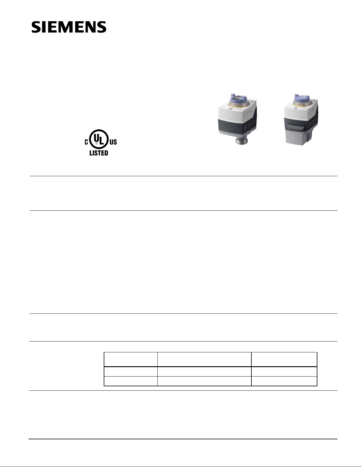
SAS61.03U
The Powermite 599 MT Series SAS Electronic Valve Actuator requires a 24 Vac or
24 Vdc supply and receives a 0 to 10 Vdc or a 4 to 20 mA control signal to proportionally
control a valve. This actuator is designed to work with Powermite 599 MT Series
terminal unit valve with a 7/32-inch (5.5 mm) stroke.
• Maintenance-free with reversible motor.
• Position indicator.
• UL listed for plenum installations.
• 0 to 10V or 4 to 20 mA.
• LED status indicator.
• Auto calibration
• Position output signal 0 to 10 Vdc.
• Manual positioning knob with stroke indication allows for repositioning.
• Mechanical spring returns the valve to its normal (fail-safe) position in power-off
conditions (SAS61.33U Actuator only).
SAS61.33U
Application
Product Numbers
Ordering
Information
For use in small to medium HVAC installations with Powermite 599 Series terminal unit
valves with a 7/32-inch (5.5 mm) stroke requiring a minimum of 90 pounds force (400N).
They can be used in liquid and low pressure steam service applications.
Product Number Actuator type Actuator Prefix Code
SAS61.03U Non-Spring Return (Fail-in-place) 364
SAS61.33U Spring Return (Fail-safe) 365
To order a complete valve plus actuator assembly from the factory, combine the
actuator prefix code with the suffix of the valve product number. See TB 251 Powermite
599 Series MT Series Terminal Unit Valve and Actuator Assembly Selections Technical
Bulletin (155-306P25) for selection procedures.
To order an actuator only, use the product number in Table 1.
Table 1. Ordering Information.
Siemens Industry, Inc.
Page 2

Technical Instructions Powermite 599 Series MT Series SAS Electronic Valve Actuator 24V Proportional Control
Running time
UL UL873
Ambient temperature
Document No. 155-682
January 19, 2016
Specifications
Power Requirements
Control Characteri stics
Operating voltage 24 Vac ± 20%, 24 Vdc, + 20%, -15%
Frequency 45 to 65 Hz
Power supply Earth ground isolating, Class 2,
24V transformer, 100 VA max.
Power consumption - running
SAS61.03U 5.3 VA
SAS61.33U 5.9 VA
Terminal
Designation
Y Control Signal 0 to 10 Vdc, 4 to 20 mA
Current draw ≤0.1 mA for 0 to 10 Vdc control
4 to 20 mA ± 1% for 4 to 20 mA control
Input impedance >100K ohms
U Position feedback
Voltage 0 to 10 Vdc ± 1%
Load impedence >10K Ω res.
Current load 1 mA max.
Z Forced control
Resistance 0 to 1000Ω, stroke proportional to R
Z connected to G Max. stroke 100%
Z connected to G0 Min. stroke 0%
Voltage Max. 24 Vac to 20%,
Max 24 Vdc+20%,-15%
Current draw ≤0.1 mA
Functional Operation
Agency Approvals
Environmental
Conditions
Physical Characteristics
at 60 Hz 30 seconds
Spring return (SAS61.33U only) <14 seconds
Nominal stroke 7/32-inch (5.5 mm)
Nominal Force 90 lbs. (400N)
Spring return (SAS61.33U only) Mechanical spring
cUL Certified to CSA C22.2 No. 24-93
Operation 23°F to 131°F (–5°C to 55°C)
Transport and storage –13°F to 158°F (–25°C to 70°C)
Humidity <95% rh
Max. permissible media temperature in valve 34°F to 248°F (1°C to 120°C)
Conduit opening Knockouts for standard 1/2-inch
conduit connector
Weight
SAS61.03U 0.9 lbs. (0.4 kg)
SAS61.33U 1.5 lbs. (0.68 kg)
Dimensions See Figure 4 and Figure 5.
Page 2 Siemens Industry, Inc.
Page 3

Powermite 599 Series MT Series SAS Electronic Valve Actuator 24V Proportional Control Technical Instruction
Document No. 155-682
January 19, 2016
Accessory
Service Kit
Operation
Mounting and
Installation
Auxiliary Switch ASC10.51 switches on or off when a certain
position is reached. The switching point can lie between 0 to 100%.
If the actuator is inoperative, replace the unit.
A zero voltage control signal returns the valve to its normal position.
In the event of a power failure:
• SAS61.03U is non-spring return and holds its last position.
• SAS61.33U returns the valve to its normal spring return position.
The position output 0 to 10 Vdc signal “U” produces position feedback to the controller.
Wiring
Figure 1. Acceptable Mounting Positions.
Mount the actuator in any position except with the actuator lower than the valve.
Figure 1 shows acceptable actuator mounting positions for water applications. The
recommended mounting position of the actuator for low pressure steam applications is
between 45° and horizontal.
• All units using the same control signal must utilize the same neutral reference (G0).
• Use earth ground isolating, step-down Class 2 transformers. Do not use auto
transformers.
• Determine supply transformer minimum rating by summing the total equipment on
circuit. The maximum rating for Class 2 step-down transformers is 100 VA.
• Do not power more than 10 actuators with one transformer.
WARNING:
Housing rated for flex conduit only.
Siemens Industry, Inc. Page 3
Page 4

Technical Instructions Powermite 599 Series MT Series SAS Electronic Valve Actuator 24V Proportional Control
WARNING:
Document No. 155-682
January 19, 2016
Wiring Diagrams
Neutral (-)
G0
Hot (+)
G
Positioning signal for 0 to 10 Vdc/4 to 20 mA
Y
M
Measuring neutral
Position feedback 0 t o 10 V dc
U
Positioning signal forced control AC/DC ≤ 24V,
Z
0 to 1000 Ω
Figure 2. Terminal Connections.
Terminal connection G is 24 Vac HOT, not ground.
CAUTION:
G0 and G must be properly wired for correct function and full life of the
actuator.
Figure 3. Wiring Diagram.
The diagram shows all possible connections. The application determines which
connections are used.
Start-up
Troubleshooting
The valve body (normally open or normally closed) determines the action of the
complete valve/actuator assembly.
• Check wiring for proper connections and secure attachments.
• Check for adequate power supply.
Page 4 Siemens Industry, Inc.
Page 5

Powermite 599 Series MT Series SAS Electronic Valve Actuator 24V Proportional Control Technical Instruction
Siemens Industry, Inc.
+ 1 847-215-1000
Your feedback is im port ant to us. If you have comments about this
Document No. 155-682
Printed in the USA
Dimensions
A B
C1
C2 D E ► ►►
Inches
5.9
3.1
0.9
2.8
1.2
0.9 4 8
mm
151
80
21.9
71.1
29.9
21.8
100
200
A B
C1
C2 D E ► ►►
Inches
5.9
3.1
0.9
3.3
1.2
0.9 4 8
mm
151
80
21.9
84.6
29.9
21.8
100
200
Document No. 155-682
January 19, 2016
Figure 4. SAS61.03U Actuator Dimensions.
Figure 5. SAS61.33U Actuator Dimensions.
Information in this publication is based on current specifications. T he company reserves the right to make changes in specifications and models as
design improvements are introduced. Product or company names mentioned herein may be t he trademarks of their respec t i ve owners.
© 2016 Siemens Indust ry, I nc.
Building Technologies Divis i on
1000 Deerfield Parkway
Buffalo Grove, IL 60089
USA
document, please send them to
sbt_technical.editor.us.sbt@siemens.com
Page 5
 Loading...