

Page 1
SCALANCE W774-1/W734-1
___________________
___________________
___________________
___________________
___________________
___________________
SIMATIC NET
Industrial Wireless LAN
SCALANCE W774-1/W734-1
Operating Instructions
07/2013
C79000
Information on the Internet
1
Introduction
2
Description
3
Mounting
4
Connection
5
Technical data
6
Approvals
7
-G8976-C325-01
Page 2
Siemens AG
Industry Sector
Postfach 48 48
90026 NÜRNBERG
GERMANY
Order number: C79000-G8976-C325-01
Ⓟ
Copyright © Siemens AG 2013.
All rights reserved
Legal information
Warning notice system
DANGER
indicates that death or severe personal injury will result if proper precautions are not taken.
WARNING
indicates that death or severe personal injury may result if proper precautions are not taken.
CAUTION
indicates that minor personal injury can result if proper precautions are not taken.
NOTICE
indicates that property damage can result if proper precautions are not taken.
Qualified Personnel
personnel qualified
Proper use of Siemens products
WARNING
Siemens products may only be used for the applications described in the catalog and in the relevant technical
re required to ensure that the products operate safely and without any problems. The permissible
ambient conditions must be complied with. The information in the relevant documentation must be observed.
Trademarks
Disclaimer of Liability
This manual contains notices you have to observe in order to ensure your personal safety, as well as to prevent
damage to property. The notices referring to your personal safety are highlighted in the manual by a safety alert
symbol, notices referring only to property damage have no safety alert symbol. These notices shown below are
graded according to the degree of danger.
If more than one degree of danger is present, the warning notice representing the highest degree of danger will
be used. A notice warning of injury to persons with a safety alert symbol may also include a warning relating to
property damage.
The product/system described in this documentation may be operated only by
task in accordance with the relevant documentation, in particular its warning notices and safety instructions.
Qualified personnel are those who, based on their training and experience, are capable of identifying risks and
avoiding potential hazards when working with these products/systems.
Note the following:
for the specific
documentation. If products and components from other manufacturers are used, these must be recommended
or approved by Siemens. Proper transport, storage, installation, assembly, commissioning, operation and
maintenance a
All names identified by ® are registered trademarks of Siemens AG. The remaining trademarks in this publication
may be trademarks whose use by third parties for their own purposes could violate the rights of the owner.
We have reviewed the contents of this publication to ensure consistency with the hardware and software
described. Since variance cannot be precluded entirely, we cannot guarantee full consistency. However, the
information in this publication is reviewed regularly and any necessary corrections are included in subsequent
editions.
07/2013 Technical data subject to change
Page 3

Contents
1 Information on the Internet ...................................................................................................................... 5
2 Introduction ............................................................................................................................................. 7
3 Description .............................................................................................................................................. 9
4 Mounting ............................................................................................................................................... 13
5 Connection ........................................................................................................................................... 21
6 Technical data ...................................................................................................................................... 33
7 Approvals .............................................................................................................................................. 37
2.1 Information on the Operating Instructions SCALANCE W774/W734 ............................................ 7
2.2 Structure of the type designation ................................................................................................... 8
2.3 Security information ....................................................................................................................... 8
3.1 Components of the product ............................................................................................................ 9
3.2 LED display .................................................................................................................................. 10
3.3 Reset button ................................................................................................................................. 12
4.1 Access restriction due to high housing temperature .................................................................... 13
4.2 Wall mounting .............................................................................................................................. 14
4.3 Installing on an S7-300 standard rail ........................................................................................... 16
4.4 Installing on an S7-1500 standard rail ......................................................................................... 17
4.5 Installing on a DIN rail / removing ................................................................................................ 18
5.1 Lightning protection, power supply and grounding ...................................................................... 21
5.2 Power supply ................................................................................................................................ 25
5.3 Ethernet ........................................................................................................................................ 26
5.4 Suitable cables for power supply and Ethernet ........................................................................... 27
5.5 Antenna connectors ..................................................................................................................... 28
5.6 Suitable antenna cables and antennas ........................................................................................ 29
5.7 C-PLUG/KEY-PLUG .................................................................................................................... 31
6.1 Dimensional drawing .................................................................................................................... 35
7.1 SCALANCE W774/W734 national approvals .............................................................................. 42
SCALANCE W774-1/W734-1
Operating Instructions, 07/2013, C79000-G8976-C325-01
3
Page 4

Page 5

1
Bitte beachten Sie die Warnhinweise und zusätzlichen Informationen in der
Kompaktbetriebsanleitung in Ihrer Sprache im Internet:
http://support.automation.siemens.com/ww/view/at/10806097
http://support.automation.siemens.com/ww/view/ch/10806097
http://support.automation.siemens.com/ww/view/de/10806097
http://support.automation.siemens.com/ww/view/li/10806097
http://support.automation.siemens.com/ww/view/lu/10806097
Please observe the warnings and additional information in the compact operating
instructions in your language in the Internet:
http://support.automation.siemens.com/ww/view/au/10806097
http://support.automation.siemens.com/ww/view/ca/10806097
http://support.automation.siemens.com/ww/view/gb/10806097
http://support.automation.siemens.com/ww/view/ie/10806097
http://support.automation.siemens.com/ww/view/us/10806097
http://support.automation.siemens.com/ww/view/za/10806097
Veuillez tenir compte des avertissements et informations supplémentaires de la notice de
service dans votre langue sur Internet:
http://support.automation.siemens.com/ww/view/be/10806097
http://support.automation.siemens.com/ww/view/ch/10806097
http://support.automation.siemens.com/ww/view/fr/10806097
http://support.automation.siemens.com/ww/view/lu/10806097
Si prega di tenere conto delle avvertenze e ulteriori informazioni nell’istruzione operativa
compatta nella relativa lingua in Internet:
http://support.automation.siemens.com/ww/view/it/10806097
Se ruega tener en cuenta las advertencias y las informaciones complementarias contenidas
en las instrucciones de servicio (resumen) en español en Internet:
http://support.automation.siemens.com/ww/view/cl/10806097
http://support.automation.siemens.com/ww/view/es/10806097
Dbejte prosím na výstražné pokyny a doplňkové informace v kompaktním návodu k obsluze
ve vašem jazyce na internetu:
http://support.automation.siemens.com/ww/view/cz/10806097
Vær venligst opmærksom på de advarselsanvisninger og ekstra informationer der findes på
dit sprog i kompaktdriftsvejledningen på internettet:
http://support.automation.siemens.com/ww/view/dk/10806097
Noudata lyhyen käyttöoppaan sisältämiä varoituksia ja huomio sen muutkin tiedot. Oman
kielisesi käyttöoppaan löydät internetistä osoitteesta:
http://support.automation.siemens.com/ww/view/fi/10806097
Λάβετε υπόψη τις υποδείξεις προειδοποίησης και τις πρόσθετες πληροφορίες των
συνοπτικών οδηγιών χρήσης που παρέχονται στη γλώσσα σας στο Διαδίκτυο:
http://support.automation.siemens.com/ww/view/gr/10806097
SCALANCE W774-1/W734-1
Operating Instructions, 07/2013, C79000-G8976-C325-01
5
Page 6
Information on the Internet
请注意互联网上精编版操作说明相应语言版本中的警告提示和附加信息:
http://support.automation.siemens.com/ww/view/cn/10806097
http://support.automation.siemens.com/ww/view/hk/10806097
http://support.automation.siemens.com/ww/view/sg/10806097
Kérjük, vegye figyelembe az interneten található, az Ön anyanyelvén íródott kompakt
használati útmutatóban található figyelmeztetéseket és további információkat:
http://support.automation.siemens.com/ww/view/hu/10806097
Skoðið vel viðvaranir og aðrar upplýsingar í notkunarleiðbeiningunum á ykkar tungumáli á
internetinu:
http://support.automation.siemens.com/ww/view/is/10806097
インターネットサイトにある各言語の注意事項および追加情報を参照してください:
http://support.automation.siemens.com/ww/view/jp/10806097
사이트에 있는 귀하의 언어로 된 콤팩트 사용 설명서에 명시된 경고 지침 및 추가 정보를
준수하십시오:
http://support.automation.siemens.com/ww/view/kr/10806097
http://support.automation.siemens.com/ww/view/kw/10806097
Neem goed nota van de waarschuwingen en extra informatie in de compacte
gebruiksaanwijzing in uw taal op internet:
http://support.automation.siemens.com/ww/view/be/10806097
http://support.automation.siemens.com/ww/view/nl/10806097
Vennligst følg advarslene og annen informasjon i den kompakte bruksanvisningen, som du
finner på ditt språk på internett:
http://support.automation.siemens.com/ww/view/no/10806097
Proszę zwrócić uwagę na ostrzeżenia oraz dodatkowe informacje w kompaktowej instrukcji
obsługi, dostępnej w odpowiednim języku w internecie:
http://support.automation.siemens.com/ww/view/po/10806097
Observera varningshänvisningarna och extrainformationerna i kompaktbruksanvisningen
som finns på ditt språk på internet:
http://support.automation.siemens.com/ww/view/se/10806097
İnternette kendi dilinizdeki kompakt işletim kılavuzunda yer alan uyarı notlarına ve ek
bilgilere lütfen dikkat edin:
http://support.automation.siemens.com/ww/view/tr/10806097
SCALANCE W774-1/W734-1
6 Operating Instructions, 07/2013, C79000-G8976-C325-01
Page 7
2
2.1
Information on the Operating Instructions SCALANCE W774/W734
Validity of the Operating Instructions
Order no.
Order no. of the US version:
Access point
SCALANCE W774-1 RJ-45
6GK5774-1FX00-0AA0
6GK5774-1FX00-0AB0
Ethernet client modules
SCALANCE W734-1 RJ-45
6GK5734-1FX00-0AA0
6GK5734-1FX00-0AB0
Purpose of the Operating Instructions
Documentation on the accompanying CD
PH_SCALANCE-W77x-W73x-WBM_76.pdf and PH_SCALANCE-W77x-W73x-CLI_76.pdf
Note
Make sure that you read the explanations and instructions in the README.txt file
These operating instructions cover the following products:
These operating instructions apply to the following software version:
● SCALANCE W774/W734 firmware as of Version 3.0
Based on the operating instructions, you will be able to install and connect up the
SCALANCE W774/W734 correctly. The configuration and the integration of the device in a
WLAN are not described in these instructions.
You will find detailed information about configuration in the SCALANCE W700 configuration
manuals on the accompanying SIMATIC NET IWLAN CD under the file name:
SCALANCE W774-1/W734-1
Operating Instructions, 07/2013, C79000-G8976-C325-01
7
Page 8
Introduction
2.2
Structure of the type designation
2.3
Security information
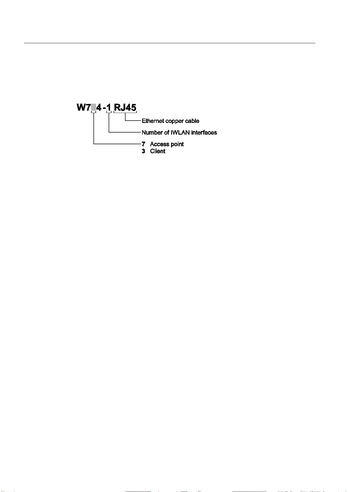
2.2 Structure of the type designation
The type designation of the device is made up of several parts that have the following
meaning:
Siemens provides automation and drive products with industrial security functions that
support the secure operation of plants or machines. They are an important component in a
holistic industrial security concept. With this in mind, our products undergo continuous
development. We therefore recommend that you keep yourself informed with respect to our
product updates. Please find further information and newsletters on this subject at:
http://support.automation.siemens.com.
To ensure the secure operation of a plant or machine it is also necessary to take suitable
preventive action (e.g. cell protection concept) and to integrate the automation and drive
components into a state-of-the-art holistic industrial security concept for the entire plant or
machine. Any third-party products that may be in use must also be taken into account.
Please find further information at: http://www.siemens.com/industrialsecurity
SCALANCE W774-1/W734-1
8 Operating Instructions, 07/2013, C79000-G8976-C325-01
Page 9

3
3.1
Components of the product
The following components are supplied with the product:
● SCALANCE W774 or SCALANCE W734
● 2 protective caps for the antenna sockets
● 1 connector for the power supply
● 1 screw for mounting on an S7-300 standard rail or S7-1500 standard rail
● SCALANCE W774/W734 safety notices in printed form
● SIMATIC NET Industrial Wireless LAN CD
Please check that the consignment you have received is complete. If the consignment is
incomplete, contact your supplier or your local Siemens office.
SCALANCE W774-1/W734-1
Operating Instructions, 07/2013, C79000-G8976-C325-01
9
Page 10
Description
3.2
LED display
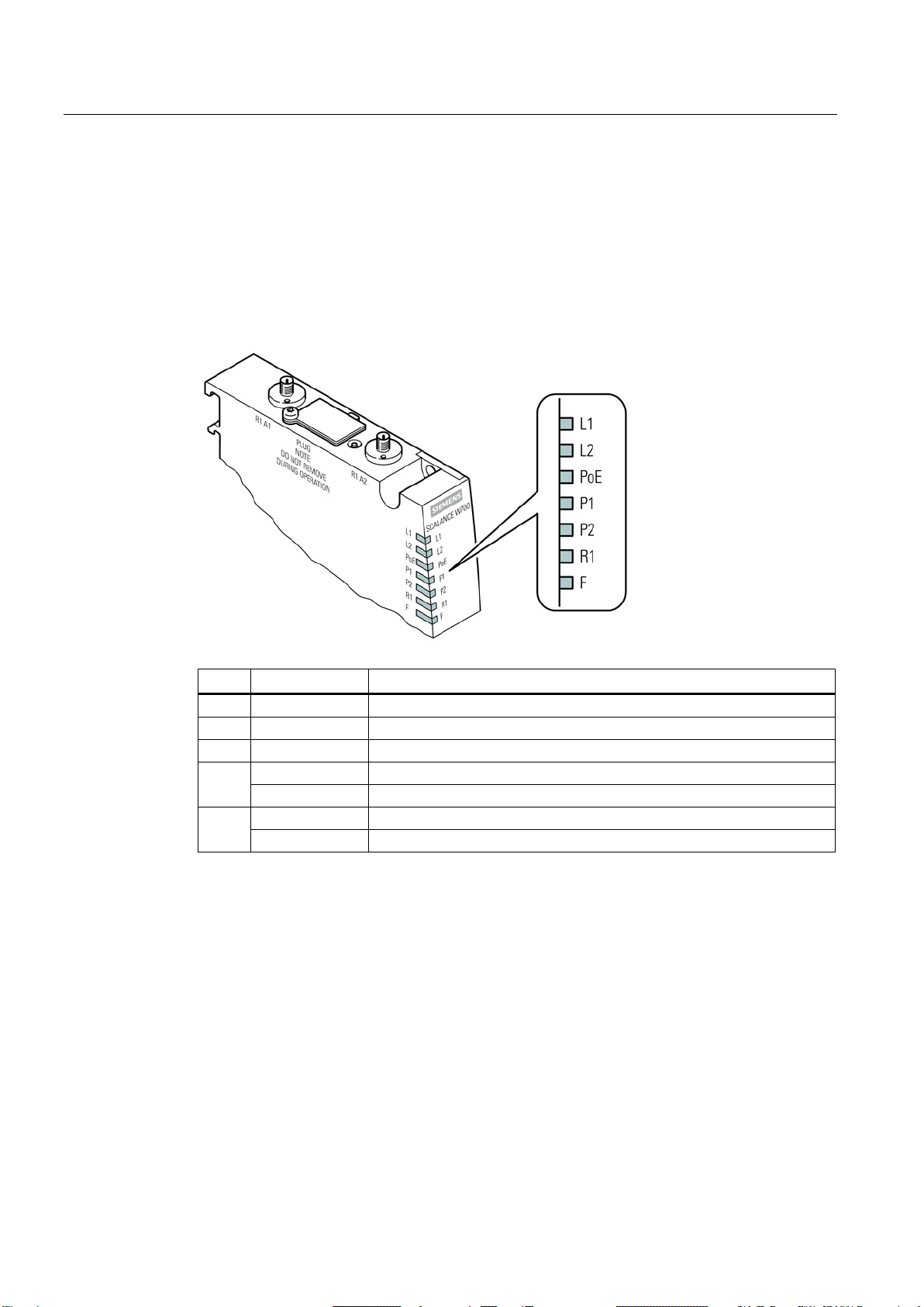
Information on operating status and data transfer
LED
Color
Meaning
L1
Green
Power supply L1.
L2
Green
Power supply L2.
PoE
Green
Power supply using Power over Ethernet.
Flashing yellow
Data transfer via the first Ethernet interface.
Green
There is a connection via the first Ethernet interface (Link).
Flashing yellow
Data transfer via the second Ethernet interface.
Green
There is a connection via the second Ethernet interface (Link).
3.2 LED display
On the front of the housing, several LEDs provide information on the operating status of the
device:
P1
P2
SCALANCE W774-1/W734-1
10 Operating Instructions, 07/2013, C79000-G8976-C325-01
Page 11
Description
Flashing yellow
Data transfer over the WLAN interface.
There is a connection via the WLAN interface.
The client is searching for a connection to an access point.
the "MAC mode" parameter and is connected to no access point.
short, 1 x long
the "MAC mode" parameter and is connected to an access point.
same time
simultaneously.
Note
Primary user (radar) on all enabled channels
If the device detects a primary user (for example radar signals) on all enabled channels of
the WLAN interface, the LED F
next 30 minutes. After this time, the device runs the scan again and c
primary user still exists. If no primary user is detected, data traffic is possible again.
The wait time of 30 minutes is necessary due to legal requirements and cannot be shortened
even by restarting the device.
3.2 LED display
R1
Green
SCALANCE W774 in access point mode:
The WLAN interface is initialized and ready for operation.
SCALANCE W774 in client mode or SCALANCE W734:
Flashing green
Green
flashing briefly
Green
flashing 3 x
F Red An error occurred during operation with the device.
Red
R1 flashing
green at the
P1
R1
Flashing yellow
and green
SCALANCE W774 in client mode or SCALANCE W734:
SCALANCE W774 in access point mode:
With 802.11h, the channel is scanned for one minute for primary users
before the channel can be used for data traffic.
SCALANCE W774 in client mode or SCALANCE W734:
The client waits for the MAC address due to the setting "Automatic" for
SCALANCE W774 in client mode or SCALANCE W734:
The client waits for the MAC address due to the setting "Automatic" for
A primary user was found on all enabled channels.
"Flashing" enabled using SIMATIC NET Primary Setup Tool (PST).
is lit and R1 flashes. No data traffic is then possible for the
SCALANCE W774-1/W734-1
Operating Instructions, 07/2013, C79000-G8976-C325-01
hecks whether a
11
Page 12
Description
3.3
Reset button
Functions of the reset button
Restart of the device
Loading new firmware
Restoring the default parameters (factory defaults)
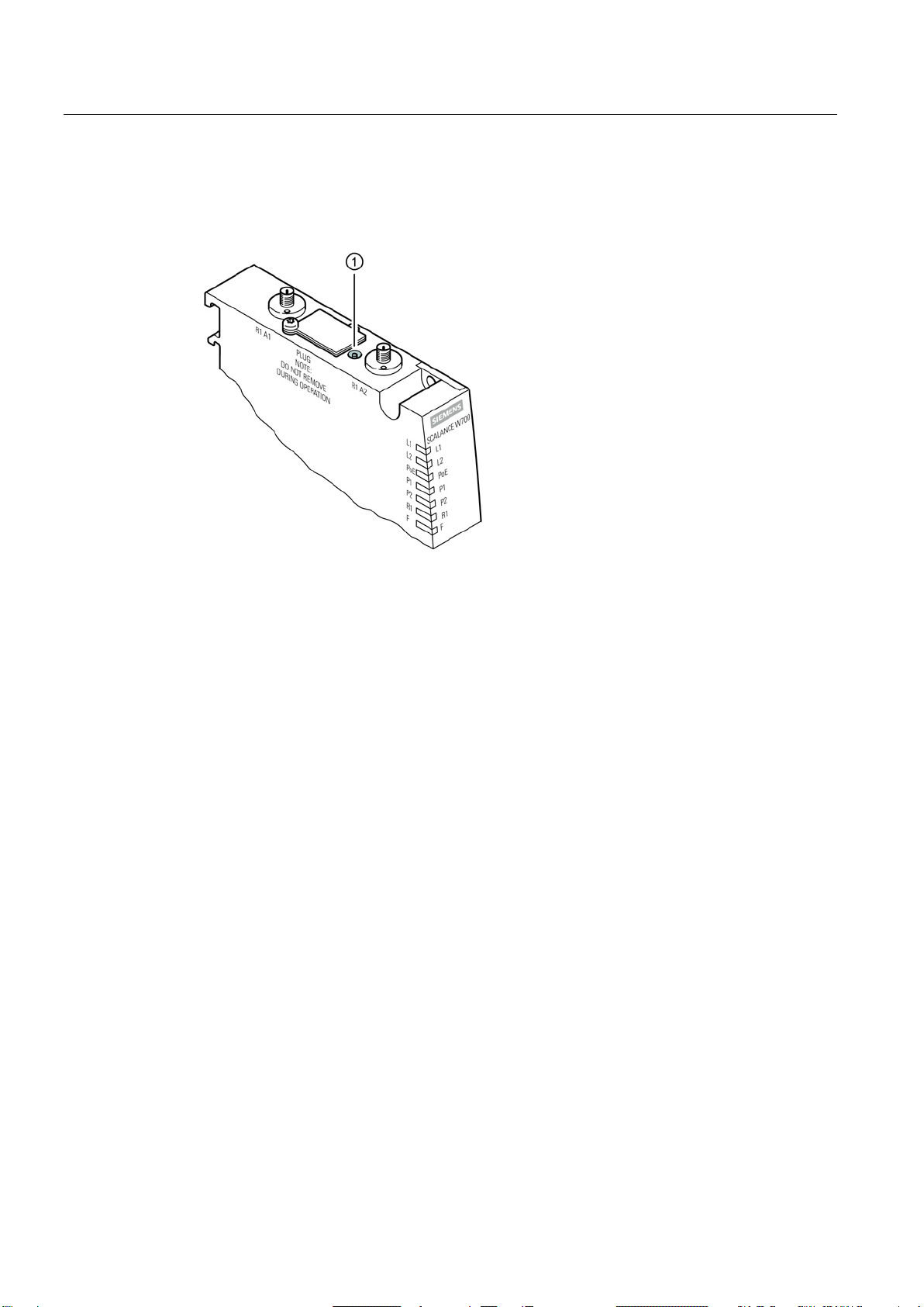
3.3 Reset button
The reset button (position ①) is on the top of the housing:
The reset button has the following functions:
●
To restart the device, press the Reset button briefly.
●
If the normal procedure with the "Load & Save" menu of Web Based Management is
unsuccessful, the reset button can be used to load new firmware. This situation can occur
if there is a power outage during the normal firmware update. You will find more detailed
information in the configuration manual SCALANCE W77x/W73x WBM.
●
You will find more detailed information in the configuration manual SCALANCE
W77x/W73x WBM.
SCALANCE W774-1/W734-1
12 Operating Instructions, 07/2013, C79000-G8976-C325-01
Page 13
4
4.1
Access restriction due to high housing temperature
WARNING
WARNING
General notes on use according to ATEX
WARNING
If a device is operated in an ambient temperature of more than 50 °C, the temperature of
the device housing may be higher than 70 °C. The device must therefore be installed so
that it is only accessible to service personnel or users that are aware of the reason for
restricted access and the required safety measures at an ambient temperature higher than
50 °C.
When used in hazardous environments corresponding to Class I, Division 2 or Class I,
Zone 2, the device must be installed in a cabinet or a suitable enclosure.
To comply with EU Directive 94/9 (ATEX95), this enclosure must meet the requirements of
at least IP54 in compliance with EN 60529.
SCALANCE W774-1/W734-1
Operating Instructions, 07/2013, C79000-G8976-C325-01
13
Page 14
Mounting
4.2
Wall mounting
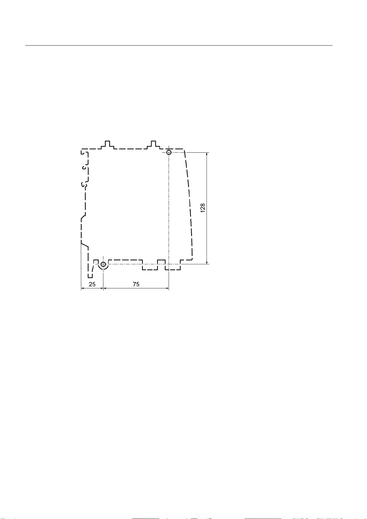
Drilling template
4.2 Wall mounting
The location of the holes for mounting the SCALANCE W774/W734 on a wall is shown in the
following figure:
SCALANCE W774-1/W734-1
14 Operating Instructions, 07/2013, C79000-G8976-C325-01
Page 15
Mounting
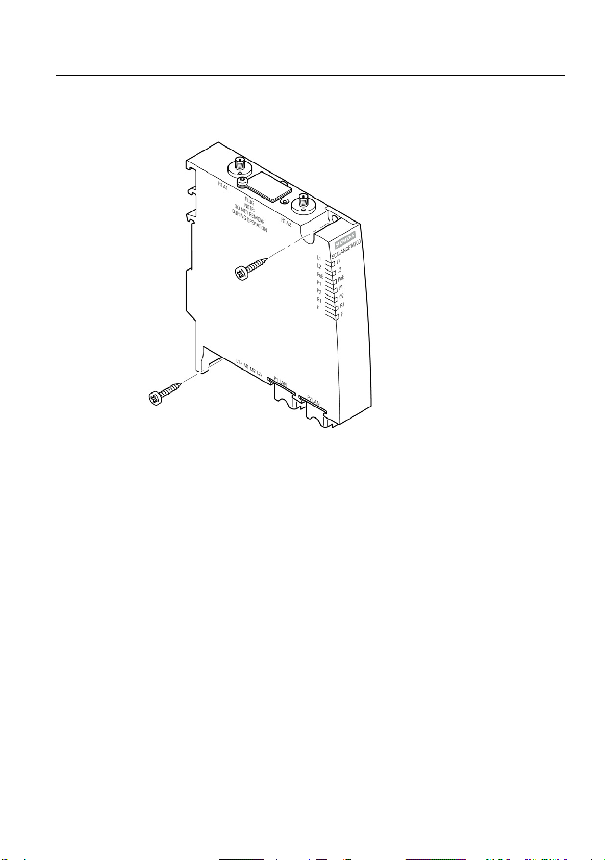
Procedure
4.2 Wall mounting
Secure the device to the wall with two screws. The screws are not supplied with the device.
The type and length of the screws depend on the type of wall.
SCALANCE W774-1/W734-1
Operating Instructions, 07/2013, C79000-G8976-C325-01
15
Page 16

Mounting
4.3
Installing on an S7-300 standard rail
Procedure
4.3 Installing on an S7-300 standard rail
Follow the steps below to fit the SCALANCE W744/W734 to an S7-300 standard rail:
1. Place the device on the upper edge of the S7-300 standard rail as shown in the figure.
2. Screw the housing to the S7-300 standard rail. The required screw ships with the
SCALANCE W744/W734.
SCALANCE W774-1/W734-1
16 Operating Instructions, 07/2013, C79000-G8976-C325-01
Page 17

Mounting
4.4
Installing on an S7-1500 standard rail
Procedure
4.4 Installing on an S7-1500 standard rail
Follow the steps below to fit the SCALANCE W744/W734 to an S7-1500 standard rail:
1. Place the device on the upper edge of the S7-1500 standard rail as shown in the figure.
2. Screw the housing to the S7-1500 standard rail. The required screw ships with the
device.
SCALANCE W774-1/W734-1
Operating Instructions, 07/2013, C79000-G8976-C325-01
17
Page 18
Mounting
4.5
Installing on a DIN rail / removing
Procedure for installation
4.5 Installing on a DIN rail / removing
Follow the steps below to fit the SCALANCE W744/W734 to a DIN rail:
1. Place the device on the upper edge of the DIN rail as shown in the figure.
2. Press the device against the DIN rail until the DIN rail slider catch locks in place.
SCALANCE W774-1/W734-1
18 Operating Instructions, 07/2013, C79000-G8976-C325-01
Page 19

Mounting
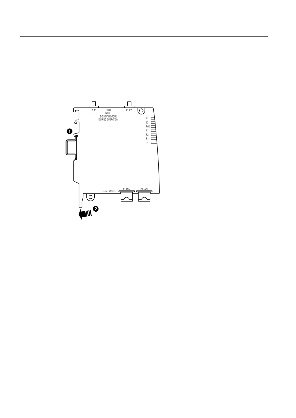
Procedure when removing
4.5 Installing on a DIN rail / removing
Follow the steps below to remove the SCALANCE W744/W734 from a DIN rail:
1. Pull the DIN rail slider down with a screwdriver.
2. Tilt the SCALANCE W774/W734 forward and remove the device from the DIN rail.
SCALANCE W774-1/W734-1
Operating Instructions, 07/2013, C79000-G8976-C325-01
19
Page 20

Mounting
4.5 Installing on a DIN rail / removing
SCALANCE W774-1/W734-1
20 Operating Instructions, 07/2013, C79000-G8976-C325-01
Page 21

5
5.1
Lightning protection, power supply and grounding
Notes on lightning protection
WARNING
Danger due to lightning strikes
Note
We recommend that you use the maintenance
Exception: When there is also DC power is supplied via the antenna cable. In this case, only
the lightning protector LP798
WARNING
Danger due to lightning strikes
Antennas installed outdoors must be within the area covered by a lightning protection
system. Make sure that all conducting systems entering from outdoors can be protected by
a lightning protection potential equalization system.
When implementing your lightning protection concept, make sure you adhere to the VDE
0182 or IEC 62305 standard.
Suitable lightning protectors are available in the range of accessories of SIMATIC NET
Industrial WLAN:
● Lightning protector LP798-1N (order no. 6GK5798-2LP00-2AA6)
● Lightning protector LP798-2N (order no. 6GK5798-2LP10-2AA6)
-free lightning protector LP798-2N.
-1N can be used.
Installing this lightning protector between an antenna and a SCALANCE W700 is not
adequate protection against a lightning strike. The LP798-1N lightening protector only
works within the framework of a comprehensive lightning protection concept. If you have
questions, ask a qualified specialist company.
SCALANCE W774-1/W734-1
Operating Instructions, 07/2013, C79000-G8976-C325-01
21
Page 22

Connection
Note
The requirements of EN61000
when a Blitzductor is used with 12 to 24 VDC:
12 to 24 VDC: VT AD 24V type no. 918 402
Vendor: DEHN+SÖ
Safety extra low voltage
WARNING
Danger to life from overvoltage, fire hazard
5.1 Lightning protection, power supply and grounding
-4-5, surge immunity tests on power supply lines, are met only
HNE GmbH+Co.KG, Hans Dehn Str. 1, Postfach 1640, D -
92306 Neumarkt, Germany
SCALANCE W700 devices are designed for operation with a directly connectable safety
extra-low voltage or with the power supply adapters available as accessories (available
only for the SCALANCE W786 device). Therefore only safety extra-low voltage (SELV) with
limited power source (LPS) complying with IEC950/EN60950/VDE0805 may be connected
to the power supply terminals (exception: Power supply adapter for 100 - 240 VAC for the
SCALANCE W786).
Take measures to prevent transient overvoltage of more than 40% of the rated voltage.
This criterion is fulfilled, if devices are operated solely with SELV (Safety Extra-Low
Voltage).
The power supply unit to supply the SCALANCE W700 must comply with NEC Class 2
(requirements of class 2 for power supply units of the "National Electrical Code, table 11
(b)") or SELV with LPS (Limited Power Source) EN 60950-1. If the power supply is
designed redundantly (two separate power supplies), both power supplies must meet these
requirements.
Exception:
Power supply with PELV (according to VDE 0100-410 or IEC 60364-4-41) is also possible if
the generated rated voltage does not exceed the voltage limits 25 VAC or 60 VDC.
SCALANCE W774-1/W734-1
22 Operating Instructions, 07/2013, C79000-G8976-C325-01
Page 23

Connection
Grounding
NOTICE
Damage to the device due to potential differences
WARNING
EXPLOSION HAZARD
WARNING
EXPLOSION HAZARD
General notes on use according to ATEX
WARNING
EXPLOSION HAZARD
5.1 Lightning protection, power supply and grounding
To fully eliminate the influence of electromagnetic interference, the device must be
grounded. There must be no potential difference between the following parts, otherwise the
device or other connected device could be severely damaged:
• Housing of the SCALANCE W700 and the ground potential of the antenna.
• Housing of the SCALANCE W700 and the ground potential of a device connected over
Ethernet.
• Housing of the SCALANCE W700 and the shield contact of the connected Ethernet
cable.
Connect both grounds to the same foundation earth or use an equipotential bonding cable.
If it is used outdoors, the device must always be connected to protective earth.
SUBSTITUTION OF COMPONENTS MAY IMPAIR SUITABILITY FOR CLASS I, DIVISION
2 OR ZONE 2.
DO NOT OPEN WHEN ENERGIZED.
DO NOT CONNECT OR DISCONNECT EQUIPMENT WHEN A FLAMMABLE OR
COMBUSTIBLE ATMOSPHERE IS PRESENT.
SCALANCE W774-1/W734-1
Operating Instructions, 07/2013, C79000-G8976-C325-01
23
Page 24

Connection
General notes on use in hazardous areas according to UL-HazLoc
WARNING
EXPLOSION HAZARD
5.1 Lightning protection, power supply and grounding
DO NOT DISCONNECT WHILE CIRCUIT IS LIVE UNLESS AREA IS KNOWN TO BE
NON-HAZARDOUS.
This equipment is suitable for use in Class I, Division 2, Groups A, B, C and D or nonhazardous locations only.
This equipment is suitable for use in Class I, Zone 2, Group IIC or non-hazardous locations
only.
SCALANCE W774-1/W734-1
24 Operating Instructions, 07/2013, C79000-G8976-C325-01
Page 25

Connection
5.2
Power supply
Socket
Pin
Assignment
L1+
24 VDC
M2
Ground
Power over Ethernet
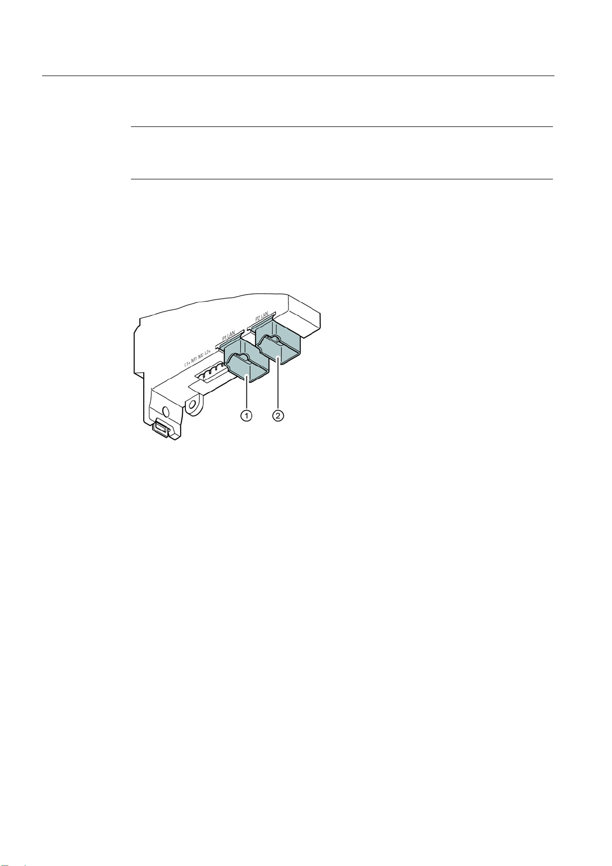
5.2 Power supply
For the power supply, there are two options with the SCALANCE W774/W734:
● Direct feed in via the four- pin socket (position
● Power over Ethernet via the Ethernet interface P2 (position
interface P1 is not capable of PoE.
①)
②). The other Ethernet
The four-pin connecting socket has the following pin assignment:
M1 Ground
L2+ 24 VDC
The SCALANCE W774/W734 supports the standards 802.3at type 1 (IEEE 802.3af ) and
IEEE 803.at type 2.
● Gigabit Ethernet
● Fast Ethernet
When you connect to gigabit Ethernet, the power supply is a phantom power supply over
data wires 1, 2, 3 and 6. This corresponds to alternative A according to IEEE 802.3af.
On an 8-wire Fast Ethernet cable, the power is supplied via the free data wires 4, 5, 7
and 8. This corresponds to alternative B according to IEEE 802.3af.
SCALANCE W774-1/W734-1
Operating Instructions, 07/2013, C79000-G8976-C325-01
25
Page 26
Connection
Note
No power sourcing equipment (PSE)
The SCALANCE W774/W734 cannot be used as a PoE power suppl
5.3
Ethernet
①
Ethernet interface P1
②
Ethernet interface P2
The power can also be supplied via this interface (Power over Ethernet).
5.3 Ethernet
y for other devices.
The SCALANCE W774/W734 has two Ethernet interfaces located on the underside of the
device.
SCALANCE W774-1/W734-1
26 Operating Instructions, 07/2013, C79000-G8976-C325-01
Page 27
Connection
5.4
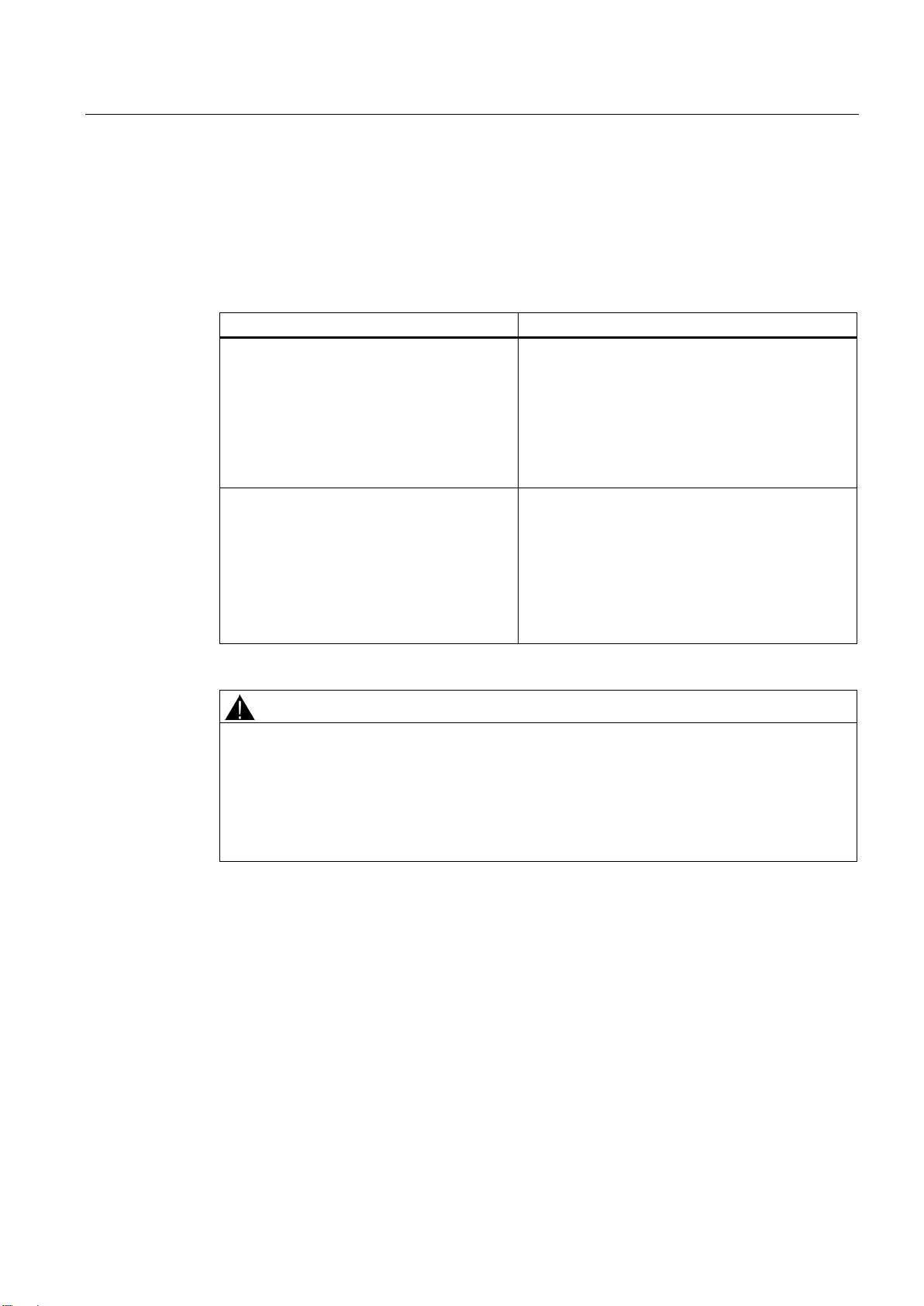
Suitable cables for power supply and Ethernet
Cable specification
Application
Specification
UL listing: Type PLTC or ITC (the three named types
have this approval)
WARNING
Only use cables suitable for high temperatures!
5.4 Suitable cables for power supply and Ethernet
The following table lists the requirements for a cable depending on the application.
Direct 24 VDC supply
Ethernet
• Round cable cross-section with
6 to 8 mm diameter.
Two-wire cable with 0.5 to 1.5 mm
per wire.
• Permitted tensile load at least
100 N.
• UL listing: Type PLTC or ITC
1. IE FC TP standard cable GP 2 x 2 (type A)
Order no.: 6XV1 840-2AH10
2. IE TP torsion cable 2 x 2 (type C)
Order no.: 6XV1 870-2F
3. IE FC TP trailing cable 2 x 2 (type C)
Order no.: 6XV1 840 3AH10
2
cross-section
If temperatures in excess of 70 °C occur on the cable or at the housing socket, or the
temperature at the branching points of the cables exceeds 80 °C, special measures need to
be taken.
If the equipment is operated in an air ambient at 45 - 60 °C, only use cables with admitted
maximum operating temperature of at least 90 °C.
SCALANCE W774-1/W734-1
Operating Instructions, 07/2013, C79000-G8976-C325-01
27
Page 28

Connection
5.5
Antenna connectors
①
Antenna connector R1 A
②
Antenna connector R1 A2
Procedure
Note
Cabinet installation
When installing the SCALANCE W774/734 in a cabinet, you need to use detached antennas.
Suitable connecting cable for a connection between SCALANCE W774/w734 and a
detached antenna are available fro
following section.
5.5 Antenna connectors
The SCALANCE W774/W734 has two antenna connectors of the type R-SMA located on the
top of the device.
1
Follow the steps below to connect a cable for an external antenna to a SCALANCE
W774/W734:
1. Insert the connector on the antenna cable into the R-SMA socket and tighten the sleeve
nut on the socket (key size SW8, tightening torque 0.6 Nm). If you only use one antenna,
you need to connect this to the device via antenna connector R1 A1 (position
2. Screw a terminating resistor to the unused antenna socket R1 R2 (position
only using one antenna.
①).
②) if you are
m SIMATIC NET. You will find detailed information in the
SCALANCE W774-1/W734-1
28 Operating Instructions, 07/2013, C79000-G8976-C325-01
Page 29
Connection
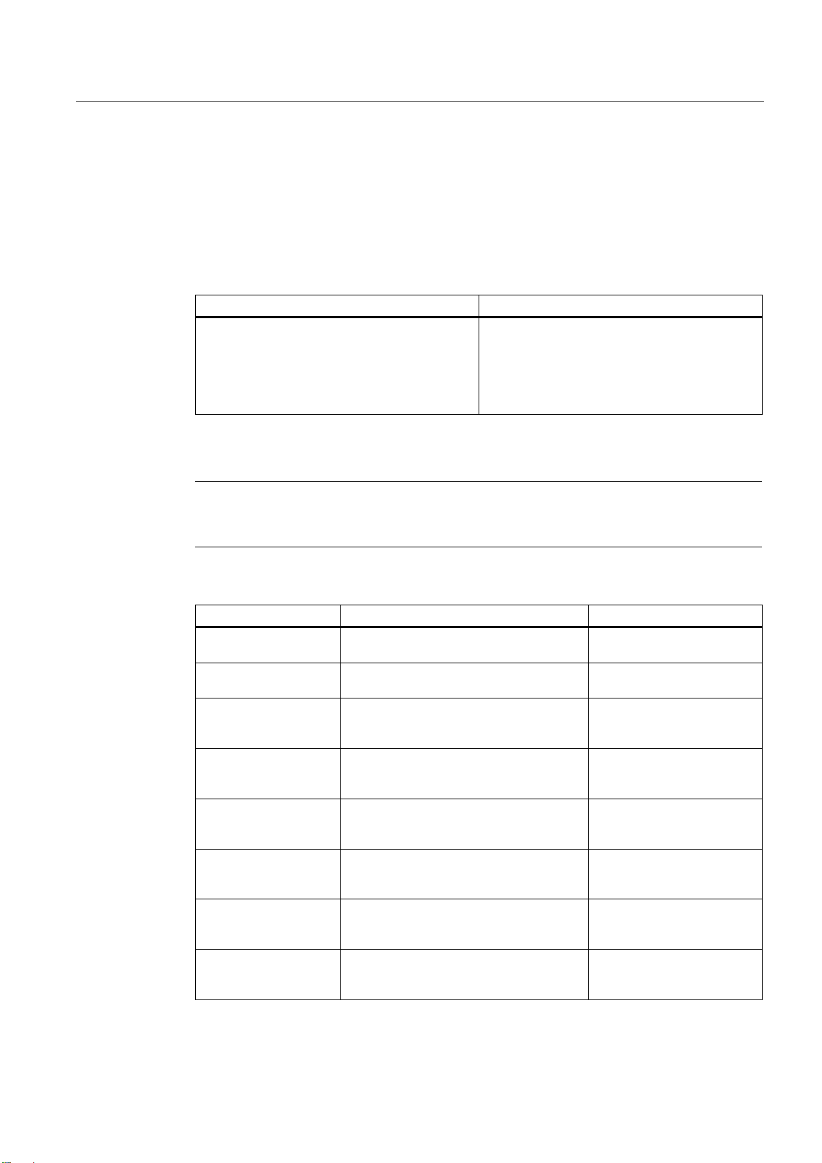
5.6
Suitable antenna cables and antennas
N-Connect/R-SMA connecting cable
Length
Order number
10 m
6XV1875-5CN10
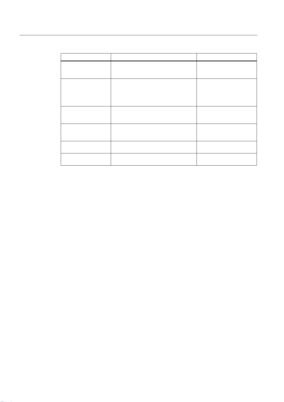
Suitable antennas
Note
When you select an antenna, keep in mind the national approvals for your SCALANCE
W774/W734.
Type
Properties
Order number
2.4 GHz, N-Connect female
5 GHz, N-Connect female
5 GHz, 2 x N-Connect female
5 GHz, 2 x N-Connect female
5 GHz, N-Connect female
2.4 GHz and 5 GHz, N-Connect female
5 GHz, 2 x N-Connect female
5.6 Suitable antenna cables and antennas
To connect an antenna with an N-Connector to a SCALANCE W774/734, the following
cables are suitable:
0.3 m
1 m
2 m
5 m
6XV1875-5CE30
6XV1875-5CH10
6XV1875-5CH20
6XV1875-5CH50
ANT792-6MN Omni antenna, mast/wall mounting, 6 dBi
ANT793-6MN Omni antenna, mast/wall mounting, 5 dBi
ANT792-8DN Directional antenna, mast/wall mounting,
14 dBi
2.4 GHz, N-Connect female
ANT793-8DJ Directional antenna, mast/wall mounting,
18 dBi
6GK5 792-6MN00-0AA6
6GK5 793-6MN00-0AA6
6GK5 792-8DN00-0AA6
6GK5 793-8DJ00-0AA0
ANT793-8DK Directional antenna, mast/wall mounting,
23 dBi
ANT793-8DP Directional antenna, mast/wall mounting,
13 dBi
ANT795-6DC Wide angle antenna, mast/
wall mounting, 9 dBi
ANT793-6DG Wide angle antenna, mast/
wall mounting, 9 dBi
SCALANCE W774-1/W734-1
Operating Instructions, 07/2013, C79000-G8976-C325-01
6GK5 793-8DK00-0AA0
6GK5793-8DP00-0AA0
6GK5 795-6DC00-0AA0
6GK5 793-6DG00-0AA0
29
Page 30
Connection
Type
Properties
Order number
2.4 GHz and 5 GHz, N-Connect female
180°.
female.
female.
GHz PE 1/2"
2.400 - 2.485 GHz, N-Connect female.
GHz PE 1/2"
5.150 - 5.875 GHz, N-Connect female.
5.6 Suitable antenna cables and antennas
ANT795-6MN Omni antenna, mounted on roof/vehicle,
6/8 dBi
ANT795-4MA Omni antenna, 3/5 dBi
2.4 GHz and 5 GHz, IP30, R-SMA
connector male for direct mounting on the
device, connector angle adjustable 0° to
ANT792-4DN RCoax helical antenna, circular
polarization, 4 dBi, 2.4 GHz, N-connect
ANT793-4MN RCoax λ5/8 antenna with vertical
polarization, 6 dBi, 5 GHz, N-connect
IWLAN RCoax cable 2.4
IWLAN RCoax cable 5
Omni antenna, 0 dBi
Omni antenna, 0 dBi
6GK5 795-6MN10-0AA6
6GK5 795-4MA00-0AA3
6GK5 792-4DN00-0AA6
6GK5 793-4MN00-0AA6
6XV1875-2A
6XV1875-2D
SCALANCE W774-1/W734-1
30 Operating Instructions, 07/2013, C79000-G8976-C325-01
Page 31
Connection
5.7
C-PLUG/KEY-PLUG
NOTICE
Do not replace the PLUG during operation
Removing the PLUG
Inserting the PLUG
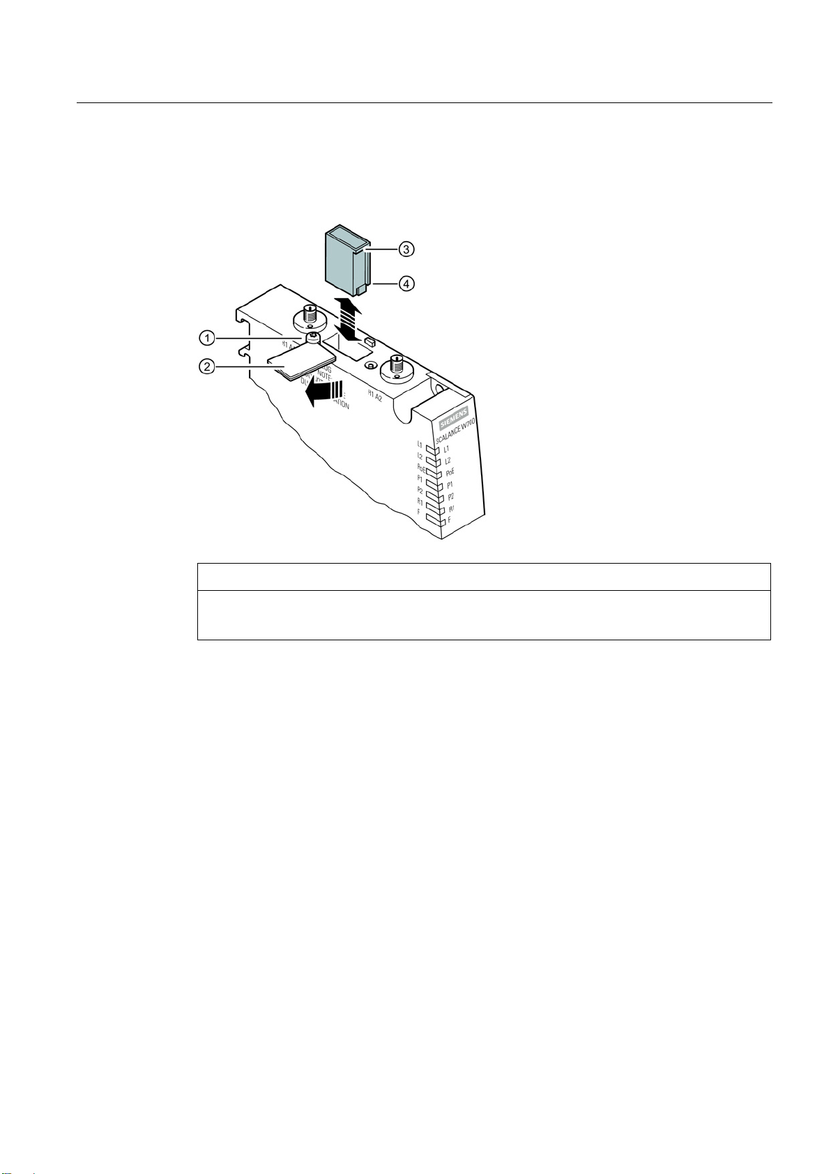
5.7 C-PLUG/KEY- PLUG
The C-PLUG/KEY-PLUG slot is on the top of the SCALANCE W774/734 housing.
A PLUG may only be removed or inserted when the device is turned off.
Follow the steps below to remove a PLUG from a SCALANCE W774/734:
1. Turn off the power to the device.
2. Release the screw slot cover (position
3. Insert a screwdriver between the front edge of the PLUG (Position
Follow the steps below to insert a PLUG in a SCALANCE W774/734:
1. Turn off the power to the device.
①) and swing the slot cover to the side (position
②).
③) and the slot and
release the PLUG.
2. The housing of the PLUG has a protruding ridge on the long side (position
has a groove at this position. Insert the PLUG correctly oriented into the slot. The PLUG
is correctly inserted when it is completely inside the device and does not jut out of the
slot.
SCALANCE W774-1/W734-1
Operating Instructions, 07/2013, C79000-G8976-C325-01
④). The slot
31
Page 32

Connection
5.7 C-PLUG/KEY- PLUG
3. Close the slot cover (position ②).
4. Tighten the screw at position
① to secure the slot cover.
SCALANCE W774-1/W734-1
32 Operating Instructions, 07/2013, C79000-G8976-C325-01
Page 33

6
SCALANCE W774/W734
Attachment to Industrial Ethernet
Quantity
2
Design
RJ-45 jack
autosensing, PoE, floating
Transmission speed
10 / 100 Mbps
Permitted cable lengths (Ethernet)
(Alternative combinations per length
range) *
Wireless interface
Quantity
2
Design
R-SMA female
Impedance
50 Ω nominal
4920 ... 5875 MHz
Electrical data
Supply voltage
24 VDC Safe Extra Low Voltage (SELV)
Permitted range
19.2 to 28.8 VDC
Design
Terminal block, 4 terminals
Properties 10/100BASE-T, IEEE 802, half duplex/full duplex, autocrossover, autonegotiation,
0 ... 55 m
0 ... 85 m
0 ... 100 m
Antenna connector
• Max. 55 m IE TP Torsion Cable
with IE FC RJ45 Plug 180
• Max. 45 m IE TP Torsion Cable
with IE FC RJ45 + 10 m TP Cord
via IE FC RJ45 Outlet
• Max. 85 m IE FC TP
Marine/Trailing/Flexible/FRNC/Fe
stoon/Food Cable with
IE FC RJ45 Plug 180
• Max. 75 m IE FC TP
Marine/Trailing/Flexible/FRNC/Fe
stoon/Food Cable + 10 m
TP Cord via IE FC RJ45 Outlet
• Max. 100 m IE FC TP Standard
Cable with IE FC RJ45 Plug 180
• Max. 90 m IE FC TP Standard
Cable + 10 m TP Cord via
IE FC RJ45 Outlet
Frequency range 2412 ... 2500 MHz
Power supply
SCALANCE W774-1/W734-1
Operating Instructions, 07/2013, C79000-G8976-C325-01
33
Page 34

Technical data
PoE to 24 VDC non-redundant design
From PoE
36 to 57 VDC
Fusing
2 A / 24 VDC
Typical
xxx mA
Maximum
xxx mA
Typical
xxx W
Maximum
xxx W
Permitted ambient conditions
installed horizontally
installed vertically
During operation
-40 ℃ to +70 ℃
During storage
-40 ℃ to +70 ℃
During transportation
-40 ℃ to +70 ℃
ambient temperature
Design, dimensions and weight
Degree of protection
IP30
Weight
xxx g
Dimensions (W x H x D)
26 x 147 (without antenna sockets) x 127 mm
Other properties
MTBF
Properties Electrically isolated, redundant design
Current consumption
Power loss at 24 VDC
Ambient temperature During operation with the rack
During operation with the rack
Relative humidity During operation ≤ 95% at 25 °C, no condensation
Operating altitude During operation ≤ 2,000 m above sea level at max. 60 °C
Contaminant concentration According to IEC 60721
Installation options
• Wall mounting
• Installation on a DIN rail
• Installation on an S7-300 standard rail
• Installation on an S7-1500 standard rail
-20 ℃ to +60 ℃
-20 ℃ to +60 ℃
SCALANCE W774-1/W734-1
34 Operating Instructions, 07/2013, C79000-G8976-C325-01
Page 35

Technical data
6.1
Dimensional drawing
6.1 Dimensional drawing
SCALANCE W774-1/W734-1
Operating Instructions, 07/2013, C79000-G8976-C325-01
35
Page 36

Technical data
6.1 Dimensional drawing
SCALANCE W774-1/W734-1
36 Operating Instructions, 07/2013, C79000-G8976-C325-01
Page 37

7
CE conformity
The products
SIMATIC NET SCALANCE W774-1 RJ45
SIMATIC NET SCALANCE W734-1 RJ45
in the version put into circulation by Siemens AG conforms to the regulations of the following
European directive:
● 99/5/EC
Directive of the European Parliament and of the Council on radio equipment and
telecommunications terminal equipment and the mutual recognition of their conformity.
Conformity with the basic requirement of the directive is attested by adherence to the
following standards:
● EN 60950-1
Information technology equipment - Safety - Part 1: General requirements
● EN 301489-1 V1.9.2
Electromagnetic compatibility and radio spectrum matters (ERM) - Electromagnetic
compatibility for radio equipment and services - Part 1 : Common technical requirements
(V1.8.1).
● EN 301489-17 V2.2.1
Electromagnetic compatibility and radio spectrum matters (ERM) - Electromagnetic
compatibility for radio equipment and services - Part 17: Specific conditions for 2.4 GHz
broadband transmission systems and 5 GHz high performance RLAN equipment
● EN 300328 V1.7.1
Electromagnetic Compatibility and Radio Spectrum Matters (ERM); — Broadband
transmission systems — Data transmission equipment operating in the 2.4 GHz ISM
band and using spread spectrum modulation techniques — Harmonized EN covering
essential requirements under article 3.2 of the R&TTE Directive
● EN 301893 V1.7.1
Broadband Radio Access Networks (BRAN) - 5 GHz high performance RLAN Harmonized EN covering essential requirements of article 3.2 of the R&TTE Directive
● EN 62311
Assessment of electronic and electrical equipment related to human exposure restrictions
for electro-magnetic fields (0 Hz – 300 GHz)
● 1999/519/EC
Council recommendation on the limitation of exposure of the general public to
electromagnetic fields (0 Hz to 300 GHz)
Devices connected to the system must meet the relevant safety regulations.
The EC Declaration of Conformity is available for the responsible authorities according to the
above-mentioned EC Directive at the following address:
SCALANCE W774-1/W734-1
Operating Instructions, 07/2013, C79000-G8976-C325-01
37
Page 38

Approvals
Note
The specified approvals apply only when the corresponding mark is printed on the product.
Certification ID
Type
Certification ID
Order number US variant
W774-1 RJ-45
MSN-W1-RJ-E2
6GK5774-1FX00-0AB0
W734-1 RJ-45
MSN-W1-RJ-E2
6GK5734-1FX00-0AB0
ATEX (explosion protection directive)
WARNING
A5E00352937
Siemens Aktiengesellschaft
Industry Sector
Postfach 4848
D-90026 Nürnberg
This declaration certifies compliance with the directives named above, but does not
guarantee any specific properties.
The following table shows the product names and the corresponding certification ID:
Order number
When using SIMATIC NET products in hazardous area zone 2, make absolutely sure that
the associated conditions in the following document are adhered to:
"Use of subassemblies/modules in a Zone 2 Hazardous Area".
This document can be found on the CD that ships with the device or on the Internet at the
following URL:
http://support.automation.siemens.com/WW/
> Product Support > Industrial Communication
Enter the document identification number
6GK5774-1FX00-0AA0
6GK5734-1FX00-0AA0
as the search term.
SIMATIC NET products meet the requirements of the EC directive:94/9/EC "Equipment and
Protective Devices for Use in Potentially Explosive Atmospheres".
ATEX classification:
II 3 G Ex nA IIC T4 Gc
SCALANCE W774-1/W734-1
38 Operating Instructions, 07/2013, C79000-G8976-C325-01
Page 39

Approvals
FM
cULus Approval Hazardous Location
FCC approval
Notice
KEMA 07ATEX0145 X
The products meet the requirements of the following standards:
● EN 60079-15: 2010 (electrical apparatus for potentially explosive atmospheres; Type of
protection "n")
● EN 60079-0: 2009 (Explosive atmospheres - Part 0: Equipment - General requirements)
The product meets the requirements of the standards:
● Factory Mutual Approval Standard Class Number 3611
● FM Hazardous (Classified) Location Electrical Equipment:
Non Incendive / Class I / Division 2 / Groups A,B,C,D / T4 and
Non Incendive / Class I / Zone 2 / Group IIC / T4
cULus Listed I. T. E. FOR HAZ. LOC.
Underwriters Laboratories Inc. complying with
● UL 60950-1 (Information Technology Equipment)
● ANSI/ISA 12.12.01-2007
● CSA C22.2 No. 213-M1987
Approved for use in
Cl. 1, Div. 2, GP A, B, C, D T4
Cl. 1, Zone 2, GP IIC T4
Report no. E240480
This device complies with Part 15 of the FCC Rules.
Operation is subject to the following two conditions:
(1) this device may not cause harmful interference, and
(2) this device must accept any interference received, including interference that may cause
undesired operation.
___________________________________________________________________________
Changes or modifications made to this equipment not expressly approved by SIEMENS may
void the FCC authorization to operate this equipment.
___________________________________________________________________________
IEEE 802.11b or g operation of this product in the USA is firmware-limited to channels 1
through 11.
SCALANCE W774-1/W734-1
Operating Instructions, 07/2013, C79000-G8976-C325-01
39
Page 40

Approvals
Notice
This transmitter must not be co-located or operating in conjunction with any other antenna or
transmitter. Professional Installation Notice:
CSA Information Technology Equipment
RSS-210 of Industry Canada
This device complies with Industry Canada licence-exempt RSS standard(s). Operation is subject to the following two conditions: (1) this device may
not cause interference, and (2) this device must accept any interference, including interference that may cause undesired operation of the device.
This equipment has been tested and found to comply with the limits for a Class B digital
device, pursuant to Part 15 of the FCC Rules. These limits are designed to provide
reasonable protection against harmful interference in a residential installation. This
equipment generates, uses and can radiate radio frequency energy and, if not installed and
used in accordance with the instructions, may cause harmful interference to radio
communications. However, there is no guarantee that interference will not occur in a
particular installation. If this equipment does cause harmful interference to radio or television
reception, which can be determined by turning the equipment off and on, the user is
encouraged to try to correct the interference by one or more of the following measures:
● Reorient or relocate the receiving antenna.
● Increase the separation between the equipment and receiver.
● Connect the equipment into an outlet on a circuit different from that to which the receiver
is connected.
● Consult the dealer or an experienced radio/TV technician for help.
___________________________________________________________________________
This equipment complies with FCC radiation exposure limits set forth for an uncontrolled
environment. This equipment should be installed and operated with minimum distance 20 cm
between the radiator and your body.
___________________________________________________________________________
To comply with FCC part 15 rules in the United States, the system must be professionally
installed to ensure compliance with the Part 15 certification. It is the responsibility of the
operator and professional installer to ensure that only certified systems are deployed in the
United States. The use of the system in any other combination (such as co-located antennas
transmitting the same information) is expressly forbidden.
CSA Certification Mark
Canadian Standard Association CSA C22.2 No. 60950-1-03
This device complies with Industry Canada licence-exempt RSS standard(s). Operation is subject
to the following two conditions: (1) this device may not cause interference, and (2) this device must
accept any interference, including interference that may cause undesired operation of the device.
i
This radio transmitter (IC: 267AA-MSN1V1)
operate wi
enna im
ant
having a gain greater than the maximum gain indicated for that type, are strictly prohibited
for use with this device.
th the antenna types listed in section 5.6 with the maximum permissible gain and required
pedance for each antenna type indicated. Antenna types not included in this list,
has been approved by Industry Canada to
SCALANCE W774-1/W734-1
40 Operating Instructions, 07/2013, C79000-G8976-C325-01
Page 41

Approvals
The device meets the requirements of the Railway standard EN 50155:2007 "Railway
Applications - Electronic equipment used on rolling stock".
The product meets the requirements of the AS/NZS 2064 standard (Class A).
Railway approval
C-TICK
Le présent appareil est conforme aux CNR d'Industrie Canada applicables aux appareils radio
exempts de licence. L'exploitation est autorisée aux deux conditions suivantes : (1) l'appareil
ne doit pas produire de brouillage, et (2) l'utilisateur de l'appareil doit accepter tout brouillage
radioélectrique subi, même si le brouillage est susceptible d'en compromettre le
fonctionnement.
Under Industry Canada regulations, this radio transmitter may only operate using an antenna
of a type and maximum (or lesser) gain approved for the transmitter by Industry Canada. To
reduce potential radio interference to other users, the antenna type and its gain should be so
chosen that the equivalent isotropically radiated power (e.i.r.p.) is not more than that
necessary for successful communication.
To reduce potential radio interference to other users, the antenna type and its gain should be
so chosen that the equivalent isotropically radiated power (e.i.r.p.) is not more than that
permitted for successful communication.
That the device for the band 5150-5250 MHz is only for indoor usage to reduce potential for
harmful interference to co-channel mobile satellite systems.
Users should also be cautioned to take note that high power radars are allocated as primary
users (meaning they have priority) of 5250-5350 MHz and 5650-5850 MHz and these radars
could cause interference and/or damage to LE-LAN devices.
This equipment complies with IC RSS-102 radiation exposure limits set forth for an
uncontrolled environment. This equipment should be installed and operated with minimum
distance 20cm between the radiator & your body.
SCALANCE W774-1/W734-1
Operating Instructions, 07/2013, C79000-G8976-C325-01
41
Page 42

Approvals
7.1
SCALANCE W774/W734 national approvals
National approvals
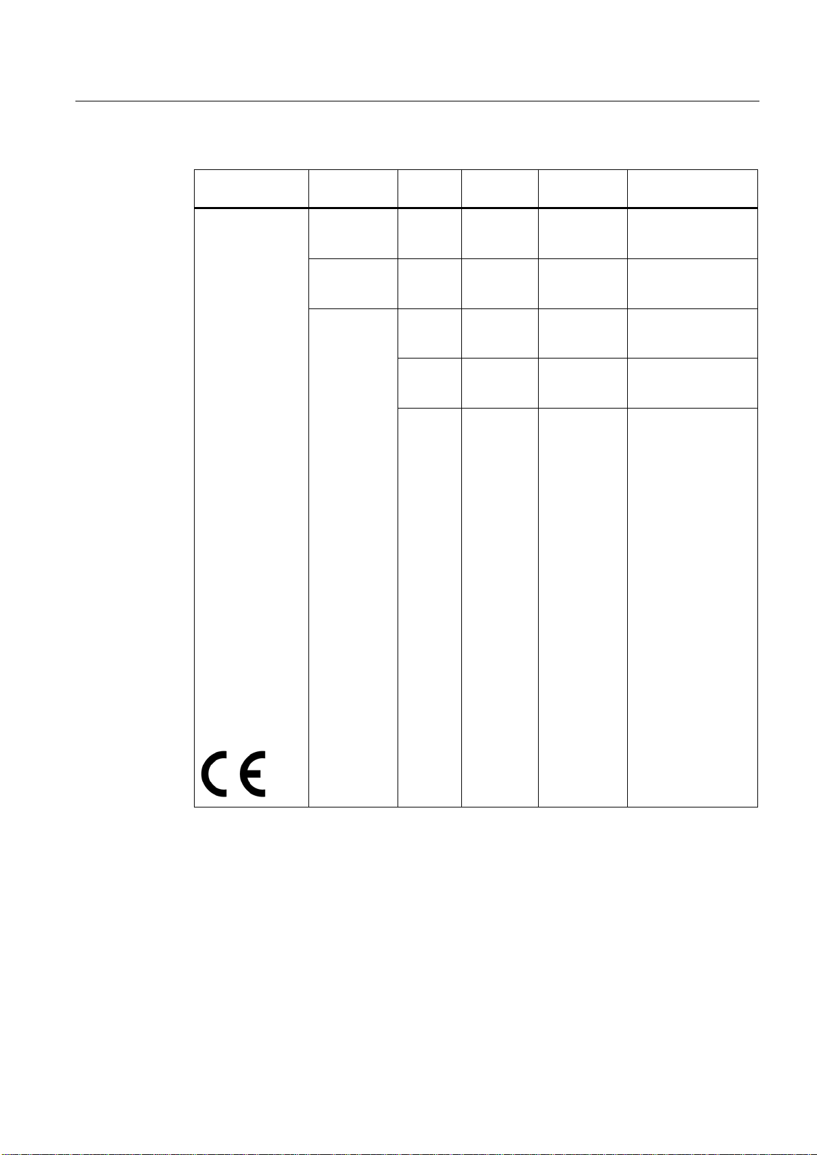
Column
Meaning
Country
Country
Mode
IEEE 802.11 standard and the TPC and / or DFS functionality, where required
CH
Channel
MHz
Frequency
PWR (EIRP)
Maximum permitted effective isotropic radiated power
Use
Permitted use indoors and / or outdoors
7.1 SCALANCE W774/W734 national approvals
The following table lists the countries in which the SCALANCE W700 product is approved.
The diamond symbol (♦) identifies all countries for which there was no approval at the time
these operating instructions were written.
The current status of the approvals can be found on the Internet at the following address:
http://www.siemens.com/funkzulassungen
SCALANCE W774-1/W734-1
42 Operating Instructions, 07/2013, C79000-G8976-C325-01
Page 43
Approvals
Country
Mode
CH
MHz
PWR
(EIRP)
Use
13
2472
48
5240
64
5320
116
5580
7.1 SCALANCE W774/W734 national approvals
Belgium
Bulgaria
Denmark
Germany
Estonia
Finland
France
Greece
Great Britain
Ireland
Iceland
Italy
Croatia
Latvia
Liechtenstein
Lithuania
Luxembourg
Malta
Macedonia
Netherlands
Norway
Austria
Poland
Portugal
Romania
Sweden
Switzerland
Serbia
Slovakia
Slovenia
Spain
Czech Republic
Turkey
Hungary
Cyprus
11g 11n 1
11a 11n
TPC
11h 11n
DFS + TPC
36
52
100
132
140
2412
-
-
-
-
-
-
5180
-
5260
-
5500
-
5660
-
5700
100 mW Indoor + outdoor
200 mW Indoor only
200 mW Indoor only
1000 mW Indoor + outdoor
1000 mW Indoor + outdoor
SCALANCE W774-1/W734-1
Operating Instructions, 07/2013, C79000-G8976-C325-01
43
Page 44

Approvals
Country
Mode
CH
MHz
PWR
(EIRP)
Use
13
2472
48
5240
64
5320
165
5825
13
2472
64
5320
140
5700
165
5825
13
2472
165
5825
7.1 SCALANCE W774/W734 national approvals
Australia
Brazil 11g 11n 1
11g 11n 1
11a 11n
TPC
11h 11n
DFS + TPC
11a 11n
TPC
11a 11n
TPC
11a 11n
TPC
36
52
149
36
100
2412
-
-
-
-
-
-
-
-
5180
-
5260
-
5745
-
2412
-
5180
-
5500
-
100 mW Indoor + outdoor
200 mW Indoor only
200 mW Indoor only
400 mW Indoor + outdoor
4000 mW Indoor + outdoor
200 mW Indoor only
1000 mW Indoor + outdoor
149
China 11g 11n 1
11a 11n
TPC
149
-
5745
-
-
-
2412
-
5745
-
4000 mW Indoor + outdoor
100 mW Indoor + outdoor
2000 mW Indoor + outdoor
SCALANCE W774-1/W734-1
44 Operating Instructions, 07/2013, C79000-G8976-C325-01
Page 45

Approvals
Country
Mode
CH
MHz
PWR
(EIRP)
Use
13
2472
8
5040
12
5060
16
5080
48
5240
64
5320
140
196
4980
1
2412
100 mW
Indoor + outdoor
10
2457
11
2462
100 mW
Indoor + outdoor
48
5240
165
5825
7.1 SCALANCE W774/W734 national approvals
Japan
Canada
Peru
Puerto Rico
USA
11g 11n 1
11a
TPC
11a 11n 36
11h 11n
DFS + TPC
11a
TPC
11g 11n
52
100
184
2412
-
-
-
-
-
2
-
-
5180
-
5260
-
5500
5700
4920
-
2417
-
200 mW Indoor + outdoor
200 mW Indoor + outdoor
200 mW Indoor only
200 mW Indoor only
200 mW Indoor + outdoor
200 mW Indoor + outdoor
200 mW Indoor + outdoor
11a 11n
TPC
36
149
5180
-
-
-
5745
-
200 mW Indoor only
400 mW Indoor + outdoor
SCALANCE W774-1/W734-1
Operating Instructions, 07/2013, C79000-G8976-C325-01
45
Page 46

Approvals
7.1 SCALANCE W774/W734 national approvals
SCALANCE W774-1/W734-1
46 Operating Instructions, 07/2013, C79000-G8976-C325-01
 Loading...