

Page 1
DE
EN
FR
NL
IT
ES
PT
SV
NO
FI
Montageanleitung
Installation Instructions
Notice de montage
Montagevoorschriften
Istruzioni di installazione
Instrucciones de montaje
Instruções de montagem
Monteringsanvisning
Monteringsanvisning
Asennusohje
DA
GR
Montagevejledning
ПдзгЯет егкбфЬуфбузт
Page 2
120
598 - 898
500
de Seite 3-7
en page 8-12
fr page 13-17
nl
pagina
18-22
it
pagina
23-27
es
página
28-32
120
> 50 cm
598 - 898
500
pt
página
33-37
sv sida 38-42
no side 43-47
fi sivu 48-52
da side 53-57
gr УелЯдб 58-62
> 65 cm
Elektrische Kochfelder
Electric cookers
Cuisinières électriques
Elektrisch fornuis
Cucine elettriche
Cocinas electricas
Fogões eléctricos
Elektrisk spis
Elektriske komfyrer
Sähköliesien osalta
Elektriske kogeplader
ЗлекфсйкЭт кпхжЯнет
2
Gas- oder kombinierte Herde
Gas or mixed cookers
Cuisinières à gaz ou mixtes
Gas- of gemengd fornuis
Cucine a gas o miste
Cocinas a gas o mixtas
Fogões a gás ou mistos
Gasspis eller kombinerad gashäll
Gasskomfyrer og blandede komfyrer
Kaasu- ja sekaliesien osalta
Gasblus og elektriske kogeplader
КпхжЯнет хгсбесЯпх Ю мейкфЭт
Page 3
Montageanleitung:
Wichtige Hinweise
Altgeräte sind kein wertloser Abfall.
Durch umweltgerechte Entsorgung können
wertvolle Rohstoffe wiedergewonnen
werden.
Bevor Sie das Altgerät entsorgen, machen
Sie es unbrauchbar.
In Übereinstimmung mit den Anforderungen
der Europäischen Richtlinie 2002/96/EG
über Elektro- und Elektronik-Altgeräte
(WEEE) ist vorliegendes Gerät mit einer
Markierung versehen.
Sie leisten einen positiven Beitrag für den
Schutz der Umwelt und die Gesundheit des
Menschen, wenn Sie dieses Gerät einer
gesonderten Abfallsammlung zuführen. Im
unsortierten Siedlungsmüll könnte ein
solches Gerät durch unsachgemäße
Entsorgung negative Konsequenzen nach
sich ziehen.
Auf dem Produkt oder der beiliegenden
Produktdokumentation ist folgendes Symbol
einer durchgestrichenen Abfalltonne
abgebildet. Es weist darauf hin, dass eine
Entsorgung im normalen Haushaltsabfall
nicht zulässig ist. Entsorgen Sie dieses
Produkt im Recyclinghof mit einer getrennten
Sammlung für Elektro- und Elektronikgeräte.
Die Entsorgung muss gemäß den örtlichen
Bestimmungen zur Abfallbeseitigung
erfolgen.
Bitte wenden Sie sich an die zuständigen
Behörden Ihrer Gemeindeverwaltung, an
den lokalen Recyclinghof für Haushaltsmüll
oder an den Händler, bei dem Sie dieses
Gerät erworben haben, um weitere
Informationen über Behandlung, Verwertung
und Wiederverwendung dieses Produkts zu
erhalten.
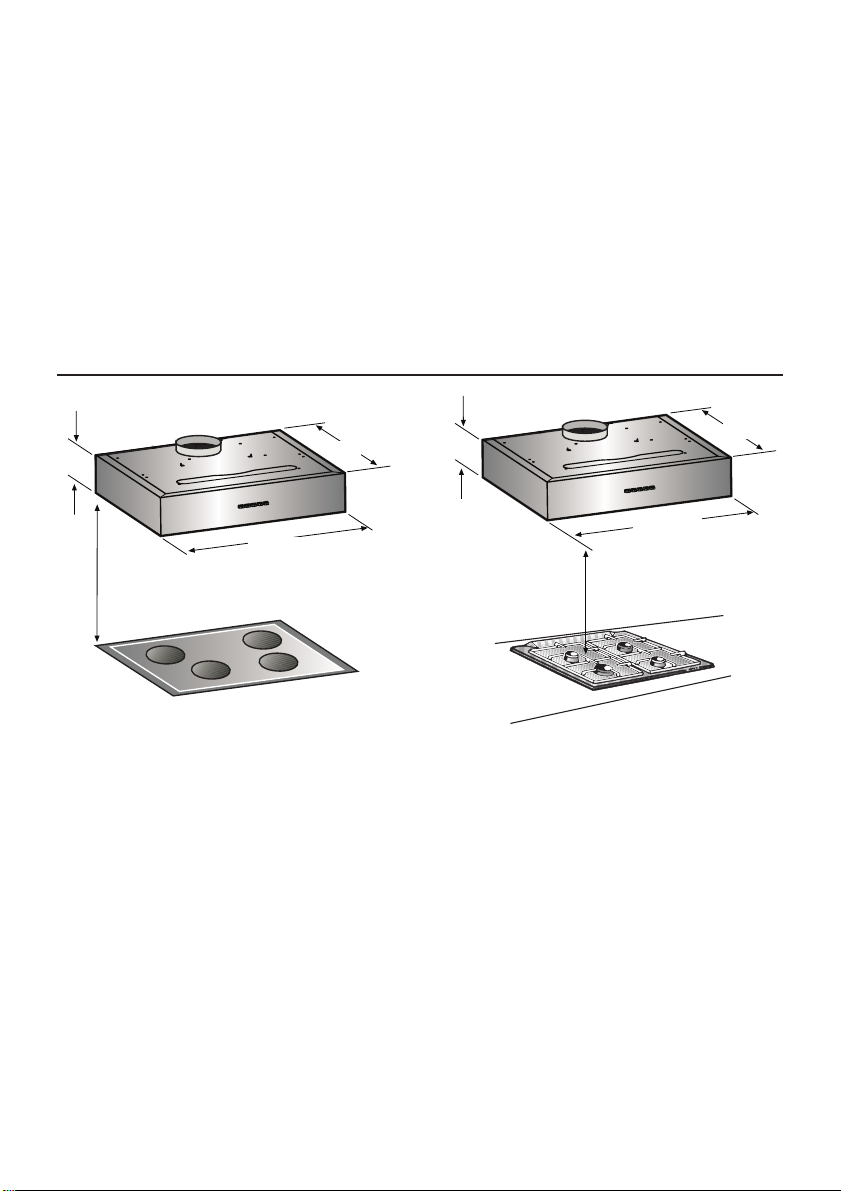
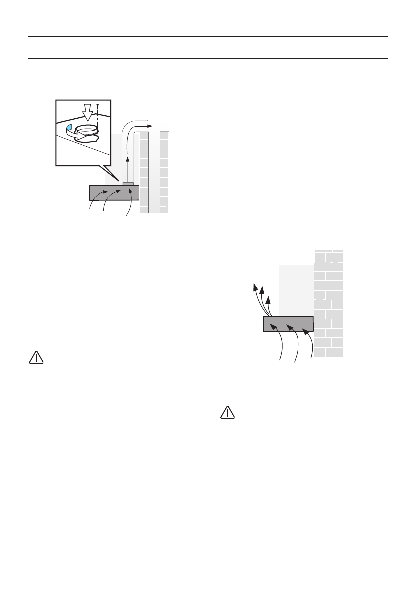
Die Dunstabzugshaube ist für Abluft und
Umluftbetrieb verwendbar.
Die Dunstabzugshaube immer über der
Mitte der Kochstellen anbringen.
Der Abstand zwischen der Abstellfläche
auf dem Kochfeld und der Unterseite der
Dunstabzugshaube darf 50cm im Fall von
elektrischen Kochfeldern und 65cm im Fall
von Gas- oder kombinierten Herden nicht
unterschreiten.
Wenn die Installationsanweisungen des
Gaskochgeräts einen größeren Abstand
vorgeben, ist dieser zu berücksichtigen.
Ihr neues Gerät wurde auf dem Weg zu
Ihnen durch die Verpackung geschützt. Alle
eingesetzten Materialien sind
umweltverträglich und wieder verwertbar.
Bitte helfen Sie mit und entsorgen Sie die
Verpackung umweltgerecht.
Über aktuelle Entsorgungswege informieren
Sie sich bitte bei Ihrem Fachhändler oder bei
Ihrer Gemeindeverwaltung.
3
Page 4
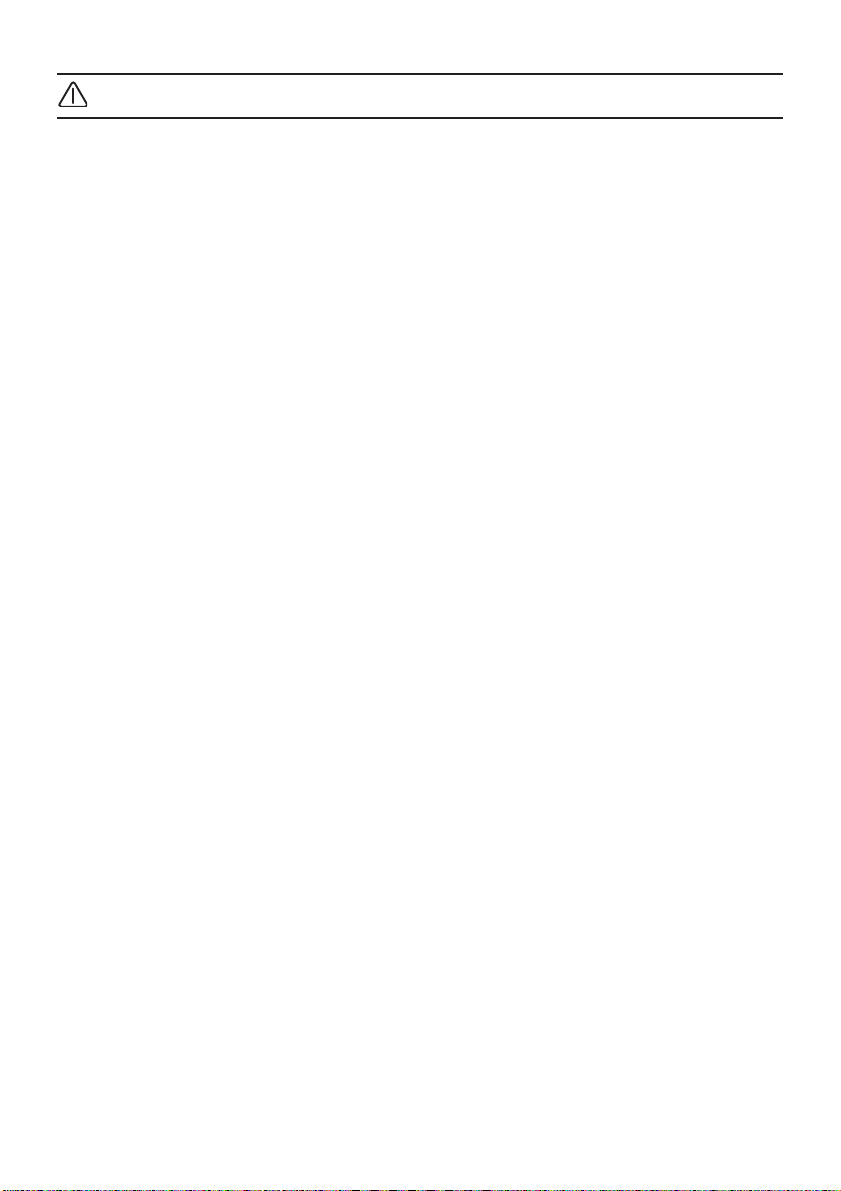
Vor der Montage
Abluftbetrieb
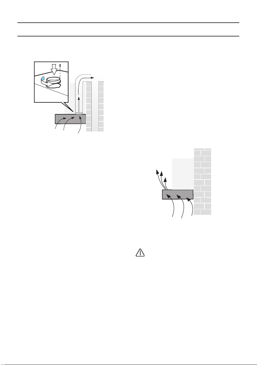
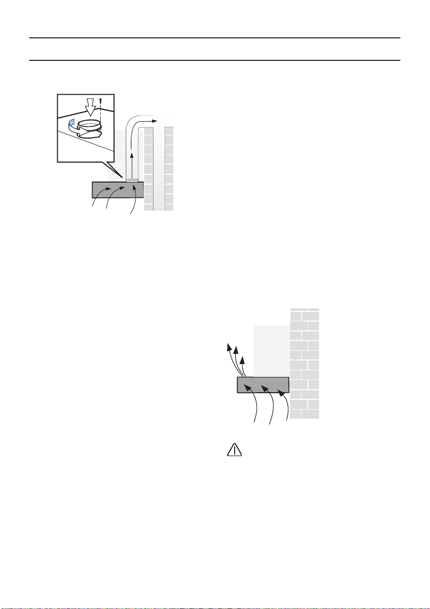
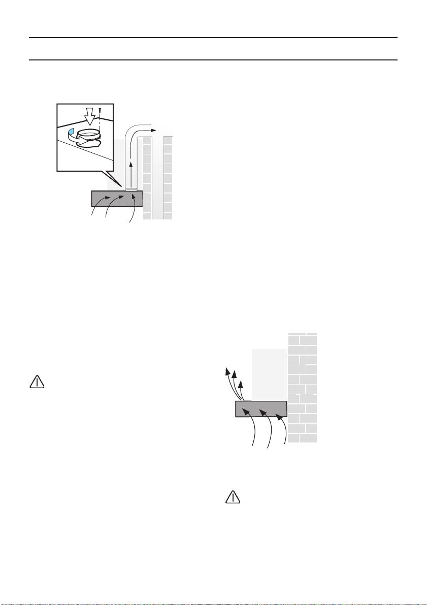
Die Abluft wird über einen Lüftungsschacht
nach oben, oder direkt durch die Außenwand
ins Freie geleitet.
Bei Abluftbetrieb sollte in der Mauerkasten
eine Rückstauklappe eingebaut werden.
Ist dem Gerät keine Rückstauklappe
beigelegt, kann sie über den Fachhandel
bezogen werden.
Wird die Abluft durch die Außenwand
geleitet, sollte ein Teleskop-Mauerkasten
verwendet werden.
Optimale Leistung der
Dunstabzugshaube:
❑ Kurzes, glattes Abluftrohr.
❑ Möglichst wenig Rohrbögen.
❑ Möglichst große Rohrdurchmesser und
große Rohrbögen.
❑ Der Einsatz von langen, rauhen
Abluftrohren, vielen Rohrbögen oder
kleineren Rohrdurchmessern führt zu
einer Abweichung von der optimalen
Luftleistung und gleichzeitig zu einer
Geräuscherhöhung.
❑ Rundrohre:
Wir empfehlen
Innendurchmesser 125 mm.
❑ Flachkanäle müssen einen
gleichwertigen Innenquerschnitt wie
Rundrohre haben.
Sie sollten keine scharfen
Umlenkungen haben.
Ø 125 mm ca. 113 cm
❑ Bei abweichenden Rohrdurchmessern:
Dichtstreifen einsetzen.
❑ Bei Abluftbetrieb für ausreichend Zuluft
sorgen.
Anschluss Abluftrohr Ø 125 mm:
❑ Abluftrohr direkt am Luftstutzen
befestigen.
2
Umluftbetrieb
❑ Mit Aktivkohlefilter, wenn keine
Möglichkeit für Abluftbetrieb vorhanden
ist.
Das komplette Montage-Set können Sie
beim Fachhandel erwerben.
Die entsprechenden Zubehör-Nummern
finden Sie am Ende dieser
Gebrauchsanleitung.
4
Page 5
Elektrischer Anschluss
Die Netzspannung muss der Spannung
entsprechen, die auf dem
Betriebsdatenschild im Innern der Haube
angegeben ist. Sofern die Haube einen
Netzstecker hat, ist dieser an zugänglicher
Stelle an eine den geltenden Vorschriften
entsprechende Steckdose anzuschließen.
Bei einer Haube ohne Stecker (direkter
Netzanschluss) oder falls der Stecker nicht
zugänglich ist, ist ein normgerechter
zweipoliger Schalter anzubringen, der unter
Umständen der Überspannung Kategorie III
entsprechend den Installationsregeln ein
vollständiges Trennen vom Netz garantiert.
Hinweis: Bevor man den Stromkreis der
Dunstabzugshaube an die Netzversorgung
verbindet und den richtigen Betrieb zu
ueberpruefen, bitte immer kontrollieren dass
die Netzversorgung immer richtig montiert
worden wird.
Hinweis! Zur Vermeidung von Gefahren darf
die Auswechselung des Stromkabels nur
vom autorisierten Kundendienst
vorgenommen werden.
Die Dunstabzugshaube darf nur an eine
vorschriftsmäßig installierte
Schutzkontaktsteckdose angeschlossen
werden.
Die Schutzkontaktsteckdose möglichst direkt
hinter der Kaminverblendung anbringen.
❑ Die Schutzkontaktsteckdose sollte über
einen eigenen Stromkreis angeschlossen
sein.
❑ Ist die Schutzkontaktsteckdose nach der
Montage der Dunstabzugshaube nicht
mehr zugänglich, muss eine
Trennvorrichtung wie beim Festanschluss
vorhanden sein.
Bei erforderlichem Festanschluss:
Die Dunstabzugshaube darf in jedem Fall
nur durch einen beim zuständigen
Elektrizitäts-Versorgungsunternehmen
eingetragenen Elektro-Installateur
angeschlossen werden.
Installationsseitig ist eine Trennvorrichtung
vorzusehen.
Als Trennvorrichtung gelten Schalter mit
einer Kontaktöffnung von mehr
als 3 mm und allpoliger Abschaltung. Dazu
gehören LS-Schalter und Schütze.
Wenn die Anschlussleitung dieses Gerätes
beschädigt wird, muss sie durch den
Hersteller oder seinen Kundendienst oder
eine ähnlich qualifizierte Person ersetzt
werden, um Gefährdung zu vermeiden.
Elektrische Daten:
Sie sind auf dem Typenschild nach
Abnahme der Filterrahmen – im Innenraum
des Gerätes – zu finden.
Bei Reparaturen die Dunstabzugshaube
generell stromlos machen.
Länge der Anschlussleitung: 1,30 m.
Diese Dunstabzugshaube entspricht den
EG-Funkentstörbestimmungen.
5
Page 6
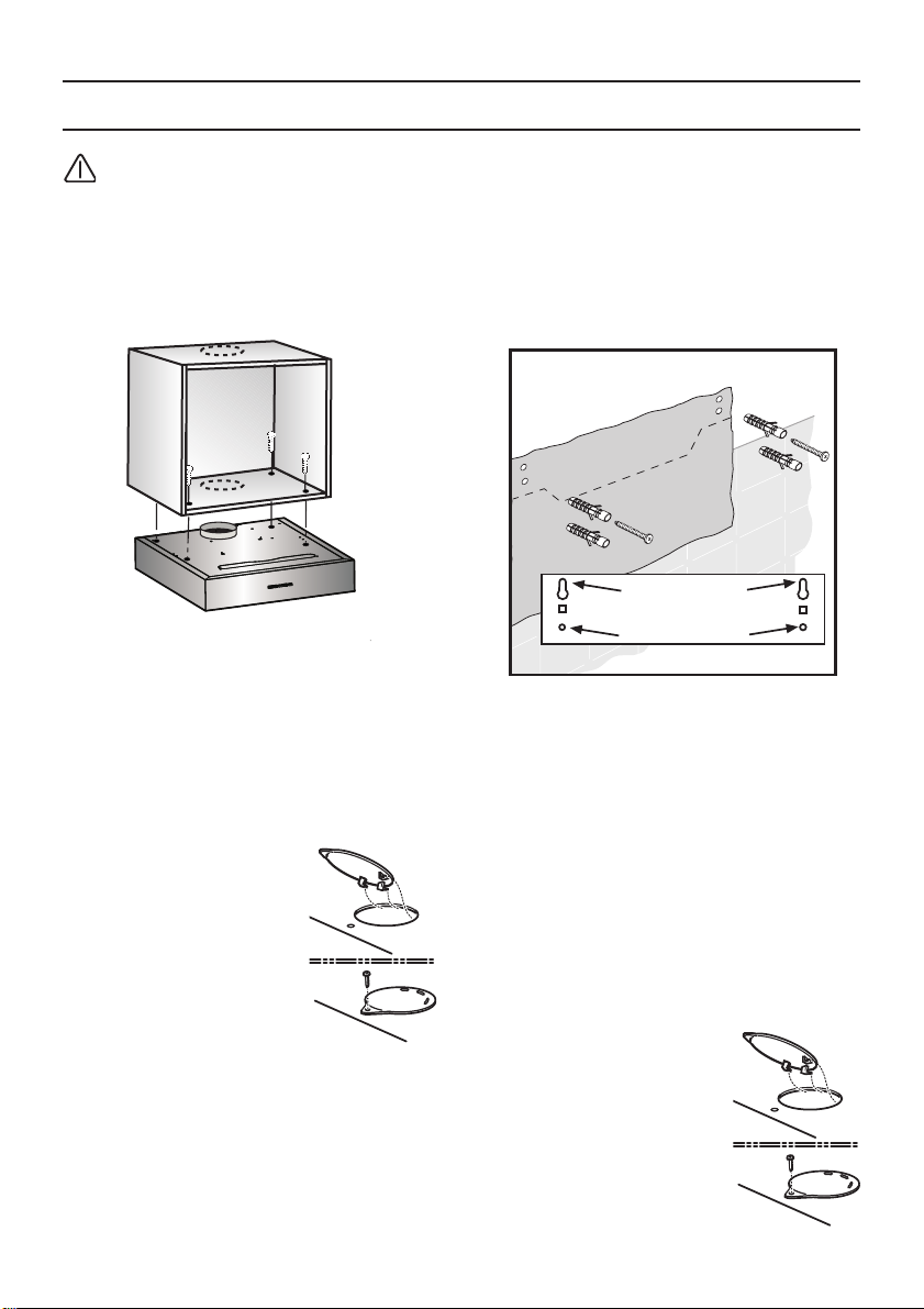
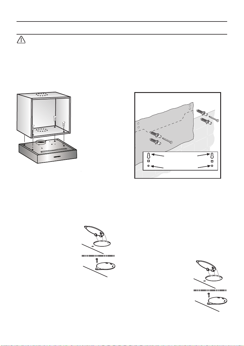
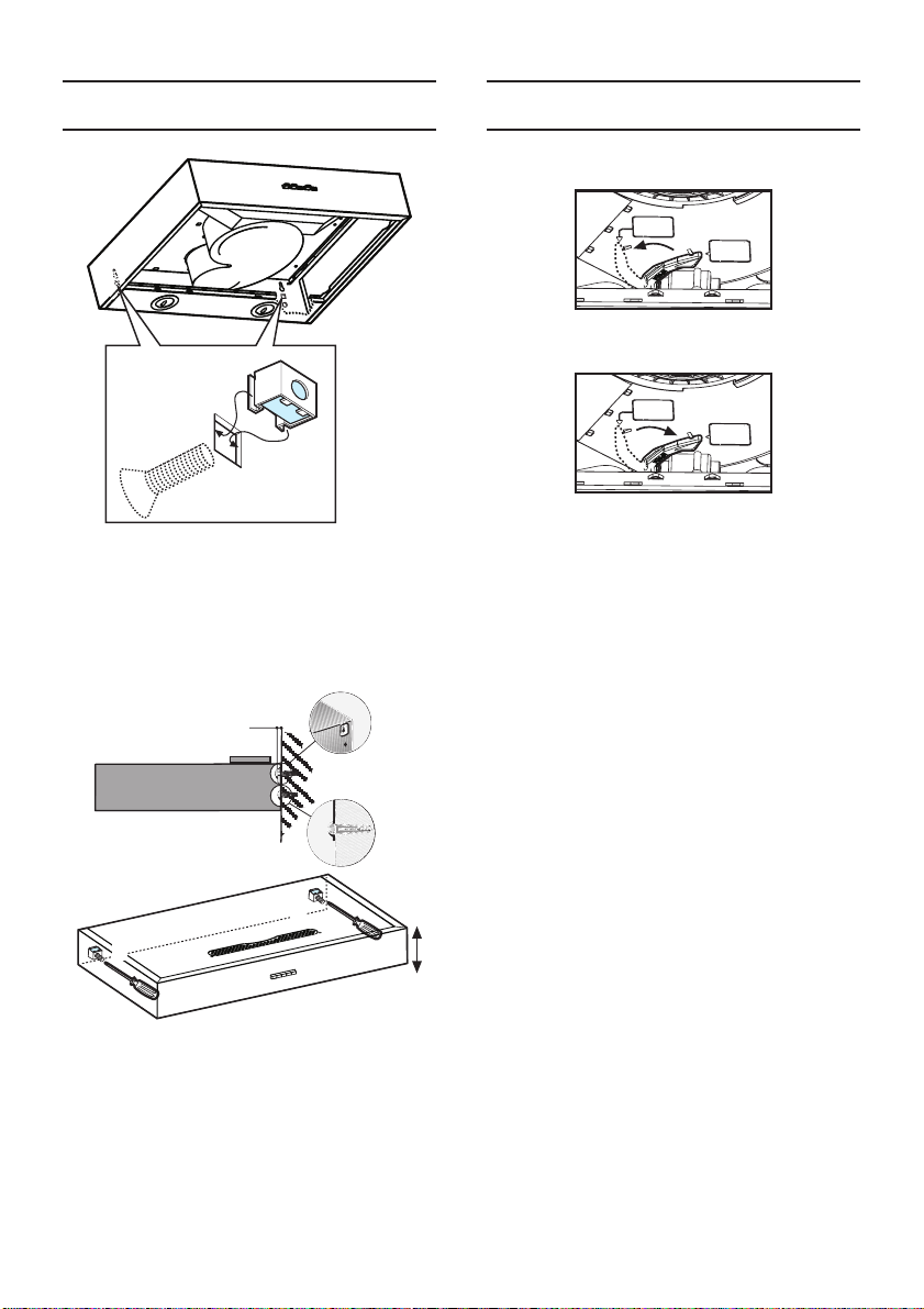
Einbauen
1
1
2
3
2
3
Achtung! Das Gerät nicht an das
Stromnetz anschließen, solange die
Installation noch nicht abgeschlossen ist.
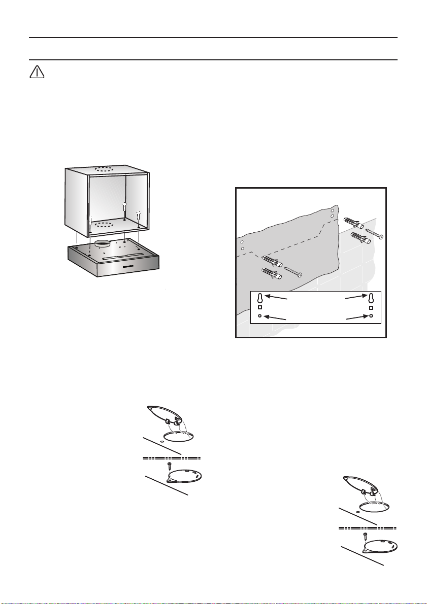
Befestigung am Oberschrank
Mit 4 Schrauben.
1. Maße für die Befestigungslöcher aus den
Bildern entnehmen oder Schablone an
den Boden des Oberschrankes anlegen.
2. Befestigungslöcher anreißen und mit
Stichel vorstechen.
Bei Abluftbetrieb nach oben, die
Abluftöffnung anreißen und aussägen.
In der UmluftbetriebVersion ist der mitgelieferte
Abluftstutzen an die
Abzugsöffnung
anzuschliessen.
1
2
Befestigung an einer Wand
Mit 4 Schrauben.
1. Befestigungslöcher anzeichnen.
Die Abmessungen können der
Bohrschablone entnommen werden.
2. Löcher mit einem Durchmesser von 8 mm
bohren und die Dübel in die Wand
stecken.
3. Die oberen Schrauben (links und
rechts) so weit anziehen, bis ein
Abstand von 7 mm zwischen dem
Schraubenkopf und der Wand erreicht
ist.
❑ Fettfilter abnehmen (siehe
Gebrauchsanleitung).
❑ Lage der Anschlussleitung
berücksichtigen, ggf. den Schrank
aussägen.
3. Filtergitter abnehmen (siehe
4. Dunstabzugshaube an den Schrankboden
6
Gebrauchsanleitung).
festschrauben.
In der UmluftbetriebVersion ist der mitgelieferte
Abluftstutzen an die
Abzugsöffnung
anzuschliessen.
1
2
Page 7
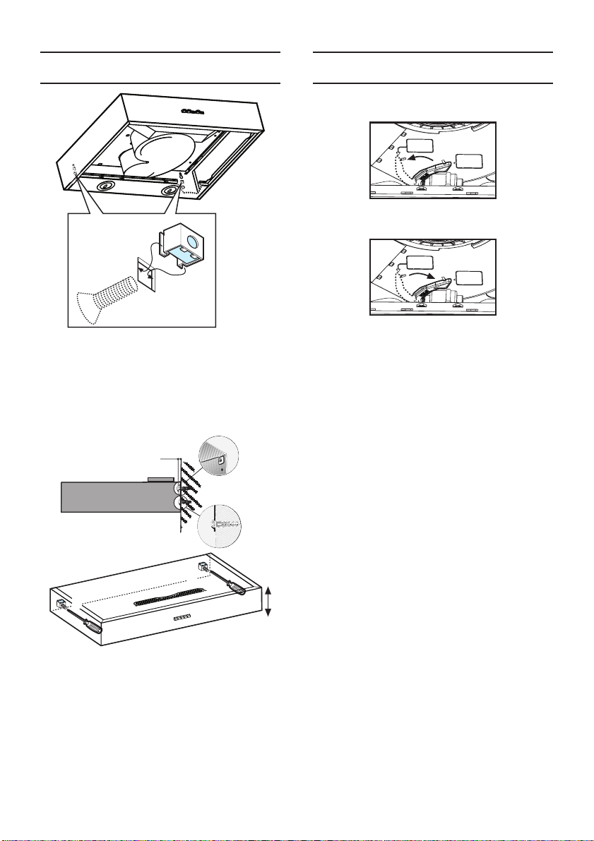
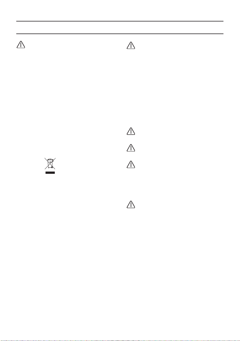
A
F
A
F
Einbauen
4
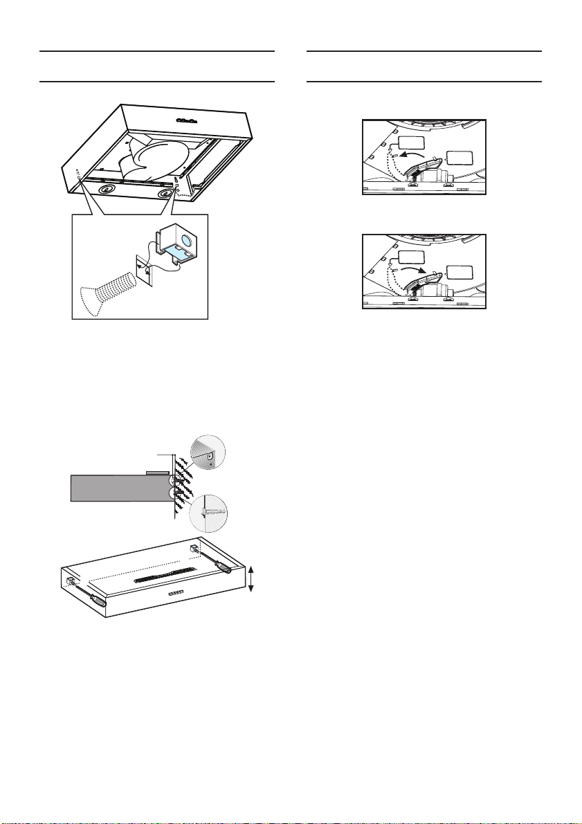
4. Die Schraubenmuttern in die rechteckigen
Öffnungen der Abzugshaube klemmen
und die mitgelieferten metrischen
Befestigungsschrauben von außen bis
zum Endanschlag einschrauben.
5
7 mm
Fertigmontage
Einstellen der Betriebsart:
❑ Abluftbetrieb: Stellung A
❑ Umluftbetrieb: Stellung F
❑ Filtergitter einsetzen.
❑ Elektrische Verbindung herstellen.
7
6
6
5. Die Abzugshaube an den oberen
Schrauben einhängen.
6. Die Abzugshaube ausrichten.
7. Die Schrauben in die unteren Löcher
stecken und festschrauben.
❑ Die Fettfilter wieder anbringen (siehe
Gebrauchsanleitung)
7
Page 8
Installation Instructions:
Important information
Old appliances are not worthless
rubbish.
Valuable raw materials can be reclaimed by
recycling old appliances.
Before disposing of your old appliance,
render it unusable.
This appliance is marked according to the
European directive 2002/96/EC on Waste
Electrical and Electronic Equipment (WEEE).
By ensuring this product is disposed of
correctly, you will help prevent potential
negative consequences for the environment
and human health, which could otherwise be
caused by inappropriate waste handling of
this product.
The symbol on the product, or on the
documents accompanying the product,
indicates that this appliance may not be
treated as household waste. Instead it
should be taken to the appropriate collection
point for the recycling of electrical and
electronic equipment. Disposal must be
carried out in accordance with local
environmental regulations for waste
disposal.
For more detailed information about
treatment, recovery and recycling of this
product, please contact your local council,
your household waste disposal service or the
shop where you purchased the product.
The extractor hood can be used in
exhaust air or circulating air mode.
Always mount the extractor hood over
the centre of the hob.
The minimum distance between the
supporting surface for the cooking vessels
on the hob and the lowest part of the range
hood must be not less than 50cm from
electric cookers and 65cm from gas or
mixed cookers.
If the instructions for installation for the
gas hob specify a greater distance, this must
be adhered to.
You received your new appliance in a
protective shipping carton.
All packaging materials are environmentally
friendly and recyclable.
Please contribute to a better environment by
disposing of packaging materials in an
environmentally-friendly manner.
Please ask your dealer or inquire at your
local authority about current means of
disposal.
8
Page 9
Prior to installation
Exhaust-air mode
The exhaust air is discharged upwards
through a ventilation shaft or directly through
the outside wall into the open.
For operating in exhaust-air mode, a oneway flap should be mounted inside the wall
ventilation box.
If no one-way flap was enclosed with the
hood, it can be obtained from a specialist
retailer.
Installing the one-way flap:
❑ Snap the one-way flap into the air pipe.
❑ Flat ducts must have an internal cross
section that equates to that of round
pipes.
There should be no sharp bends.
Ø 150 mm approx. 177 cm
❑ If pipes have different diameters:
Insert sealing strip.
❑ For exhaust-air mode, ensure that there
is an adequate supply of fresh air.
Connecting a Ø 150 mm exhaust-air pipe:
❑ Mount the pipe directly onto the air outlet
on the hood.
2
.
Circulating-air mode
The two lightly sprung flaps must be
able to move upwards.
If the exhaust air is going to be
discharged into the open, a telescopic wall
box should be fitted into the outside wall.
❑ For optimum extractor hood efficiency:
❑ Short, smooth air exhaust pipe.
❑ As few bends in the pipe as possible.
❑ Diameter of pipe to be as large as
possible and no tight bends in pipe.
If long, rough exhaust-air pipes, many
pipe bends or smaller pipe diameters
are used, the air extraction rate will no
longer be at an optimum level and
there will be an increase in noise.
❑ Round pipes:
We recommend Internal diameter:
120 mm
❑ With activated carbon filter if exhaust-air
mode is not possible.
The complete installation set can be
obtained from specialist outlets.
The corresponding accessory numbers can
be found at the end of these operating
instructions.
9
Page 10
Electrical connection
The mains power supply must correspond to
the rating indicated on the plate situated
inside the hood. If provided with a plug
connect the hood to a socket in compliance
with current regulations and positioned in an
accessible area. If it not fitted with a plug
(direct mains connection) or if the plug is not
located in an accessible area apply a bipolar switch in accordance with standards
which assures the complete disconnection of
the mains under conditions relating to overcurrent category III, in accordance with
installation instructions.
Warning! Before re-connecting the hood
circuit to the mains supply and checking the
efficient function, always check that the
mains cable is correctly assembled.
Warning! Power cable replacement must be
undertaken by the authorized service
assistance centre or similar qualified person.
Connect the hood to a norm complying plug
only. The plug should be located in an
accessible zone.
❑ The plug must be equipped with a
protection circuit.
❑ If after installation the plug can not be
reached, a disconnecting device must be
envisaged.
Fixed installation:
The fixed installation can be carried out by a
qualified and authorized person only.
Envisage an omnipolar switch having a
contact opening of at least 3mm, including
an automatic circuit breaker.
The cable must be replaced by the
manufacturer, the assistance centre or a
qualified and authorized person only, in
order to avoid any dangers.
Electrical data:
The technical data of the device are on the
distinctive label inside the device behind the
grease filters.
In case of repair, disconnect the electric
supply from the cooker hood.
Length of the feeding cable: 1,30m.
The hood complies with the EMC directives.
10
Page 11
1
1
2
3
2
3
Installation
WARNING! Do not connect the appliance to the mains until the installation is fully
complete.
To a wall-hanging cupboard
With 4 screws.
1. Dimensions for the mounting boreholes
can be found in, or place a template on
the base of the wallhanging cupboard.
2. Mark the mounting holes and make pilot
holes with a bradawl.
In exhaust-air mode (upwards) mark the
exhaust-air opening and saw out.
In circulating-air mode,
apply the plug supplied
to close the exhaust
hole.
❑ Consider the location of the connection
cable; if required, saw out the cupboard.
3. Remove the filter grille (see Instructions
4. Screw the extractor hood to the base of
for use).
the cupboard.
To the wall
With 4 screws.
1. Mark mounting boreholes.
Dimensions can be found in or use
template.
2. Drill 8 mm dia. holes and insert wall
plugs flush with the wall.
3. Screw in the upper screws (on left and
right) until there is a gap of approx.
1
2
7 mm between the screw head and the
wall.
❑ Remove the grease filters (see
Instructions for use).
In circulating-air mode,
apply the plug supplied
to close the exhaust
hole.
1
2
11
Page 12
A
F
A
F
Installation Final assembly
Selecting the operating mode:
❑ Exhaust-air mode: Position A
4
❑ Circulating-air mode: Position F
4. Secure the nuts inside the box of the
hood on the square slots and screw in,
from outside, the metric screws supplied
to their maximum.
❑ Refit the grease filter.
❑ Connect to the power supply.
5
7 mm
7
6
6
5. Hook the hood to the upper screws.
6. Adjust the structure of the hood.
7. Insert and totally screw the screws in the
lower holes for the final fixing.
❑ Reinstall the grease filters (see
Instructions for use)
12
Page 13
Notice de montage:
Remarques importantes
Les anciens appareils ne sont pas des
déchets sans valeur.
Leur élimination respectueuse de
l’environnement permet de récupérer de
précieuses matières premières.
Avant de vous débarrasser de l’appareil,
rendez-le inutilisable.
Cet appareil porte le symbole du recyclage
conformément à la Directive Européenne
2002/96/CE concernant les Déchets
d’Équipements Électriques et Électroniques
(DEEE ou WEEE).
En procédant correctement à la mise au
rebut de cet appareil, vous contribuerez à
empêcher toute conséquence nuisible pour
l’environnement et la santé de l’homme.
Le symbole
sur la documentation qui l’accompagne
indique que ce produit ne peut en aucun cas
être traité comme déchet ménager. Il doit par
conséquent être remis à un centre de
collecte des déchets chargé du recyclage
des équipements électriques et
électroniques.
Pour la mise au rebut, respectez les normes
relatives à l’élimination des déchets en
vigueur dans le pays d’installation.
Pour obtenir de plus amples détails au sujet
du traitement, de la récupération et du
recyclage de cet appareil, veuillez vous
adresser au bureau compétent de votre
commune, à la société de collecte des
déchets ou directement à votre revendeur.
présent sur l’appareil ou
Cette hotte peut évacuer l’air à
l’extérieur ou le recycler.
Fixez toujours la hotte bien centrée au-
dessus des foyers de la table de cuisson.
La distance minimum entre la superficie
de support des récipients sur le dispositif de
cuisson et la partie la plus basse de la hotte
de cuisine ne doit pas être inférieure à 50cm
dans le cas de cuisinières électriques et de
65cm dans le cas de cuisinières à gaz ou
mixtes.
Si les instructions d’installation du
dispositif de cuisson au gaz spécifient une
plus grande distance, il faut en tenir compte.
Pour vous parvenir en parfait état, votre
nouvel appareil a été conditionné dans un
emballage qui le protège efficacement. Tous
les matériaux d’emballage utilisés sont
compatibles avec l’environnement et
recyclables. Aidez-nous à éliminer
l’emballage en respectant l’environnement.
Demandez à votre revendeur ou à votre
mairie quelles sont les formes de recyclage
actuellement possibles.
13
Page 14
Avant le montage
Evacuation de l’air à l’extérieur
L’air vicié est évacué vers le haut par un
conduit d’aération ou directement à l’air libre
par traversée du mur extérieur.
Si la hotte évacue l’air à l’extérieur,
incorporer un volet anti-refoulement dans la
ventouse télescopique.
Si l’appareil a été fourni sans volet anti
refoulement, vous pouvez vous le procurer
dans le commerce spécialisé.
Si l’air vicié traverse le mur extérieur,
utilisez une ventouse télescopique.
Pour que la hotte aspirante ait le meilleur
rendement, veillez à ce que:
❑ Le conduit d’évacuation soit court et lisse.
❑ Il ait le moins possible de coudes.
❑ Il ait le plus fort diamètre et que les
coudes soient les plus arrondis possibles.
❑ L’emploi de conduits d’air vicié longs,
rugueux, formant de nombreux coudes
ou d’un trop petit diamètre fait
descendre le débit d’air en dessous du
débit optimal, tout en accroissant le
bruit d’aspiration.
❑ Conduits de section ronde:
Nous recommandons des conduits au
diamètre intérieur de 125 mm.
❑ Les conduits plats doivent avoir une
section intérieure équivalente au
diamètre intérieur des conduits ronds.
Les conduits ne doivent comporter
aucun coude prononcé.
125 mm Ø = 113 cm
❑ Si les conduits ont des diamètres
différents: utilisez du ruban adhésif à
étancher.
❑ Si la hotte évacue l’air à l’extérieur,
veillez à ce que l’apport d’air soit
suffisant.
Branchement du conduit d’évacuation Ø
125 mm: .
❑ Fixez le conduit d’évacuation directement
sur l’orifice.
2
de section.
Mode Air recyclé
❑ Avec filtre à charbon actif, lorsqu’il n’est
pas possible d’évacuer l’air aspiré par la
hotte.
Vous pouvez vous procurer le kit de
montage complet auprès de votre revendeur
spécialisé.
Vous trouverez les numéros de référence
des accessoires correspondants à la fin de
la présente notice d’utilisation.
14
Page 15
Branchement électrique
La tension électrique doit correspondre à la
tension reportée sur la plaque signalétique
située à l’intérieur de la hotte. Si une prise
est présente, branchez la hotte dans une
prise murale conforme aux normes en
vigueur et placée dans une zone accessible.
Si aucune prise n’est présente
(raccordement direct au circuit électrique),
ou si la prise ne se trouve pas dans une
zone accessible, appliquez un disjoncteur
normalisé pour assurer de débrancher
complètement la hotte du circuit électrique
en conditions de catégorie surtension III,
conformément aux règlementations de
montage.
Attention! Avant de rebrancher le circuit de
la hotte à l’alimentation électrique et d’en
vérifier le fonctionnement correct, contrôlez
toujours que le câble d’alimentation soit
monté correctement.
Attention! La substitution du câble
d’alimentation doit être effectuée par le
service d’assistance technique autorisé de
façon à prévenir tout risque.
Raccorder la hotte uniquement à une
prise conforme aux normes. La prise doit
être placée dans une zone accessible.
❑ La prise doit être dotée de son propre
circuit de protection.
❑ Si après l'installation la prise n'est plus
accessible, il faut prévoir un dispositif
d'interruption du circuit.
Installation fixe:
L'installation fixe peut être réalisée
uniquement par une personne compétente
et autorisée. Prévoir un interrupteur
omnipolaire avec une ouverture des contacts
de minimum 3 mm, ainsi qu'un disjoncteur.
Le remplacement du câble doit être effectué
uniquement par le producteur, par le centre
d'assistance ou par une personne
compétente et autorisée pour éviter
d'éventuels dangers.
Données électriques:
Les données techniques de l'appareil se
trouvent sur l'étiquette des caractéristiques à
l'intérieur de l'appareil derrière les filtres antigraisses.
En cas de réparation, débrancher la hotte
du circuit électrique.
Longueur du câble d'alimentation: 1,30 m.
La hotte est conforme aux directives EMC.
15
Page 16
Encastrement
1
1
2
3
2
3
Attention! Ne pas raccorder l’appareil
au circuit électrique avant que le montage ne
soit complètement terminé.
Fixation sous un placard en appui
mural
Par 4 vis.
1. Reportez sur la paroi inférieure du
placard les cotes d’écartement inscrites
dans les figures ou appliquez le gabarit
de perçage contre cette paroi.
2. Marquez les emplacements des trous de
fixation spécifiés.
Si la hotte doit évacuer l’air à l’extérieur
par le haut, marquez aussi l’emplacement
de l’orifice à ménager dans le placard
puis découpez-le à la
scie.
En mode air recyclé,
appliquer le bouchon
fourni dans le kit pour
fermer le trou
d'évacuation.
❑ Le cordon de
branchement doit circuler correctement.
Si nécessaire, effectuez une découpe
dans le placard.
3. Retirez la grille du filtre (voir la notice
d’utilisation).
4. Vissez la hotte aspirante contre le fond du
placard.
Fixation à une paroi
Avec 4 vis.
1. Marquer les trous pour le montage. Les
dimensions peuvent être trouvées à partir
du gabarit de forage.
2. Faire des trous de 8 mm de diamètre et
insérer les tampons à fil de paroi.
3. Visser les vis supérieures (à droite et à
1
2
gauche) jusqu'à ce qu'il n'y ait plus qu'un
espace d'environ 7mm entre la tête de la
vis et la paroi.
❑ Enlever les filtres anti-graisses (voir
Instructions pour l'utilisation).
En mode air recyclé,
appliquer le bouchon
fourni dans le kit pour
fermer le trou
d'évacuation.
2
1
16
Page 17
A
F
A
F
Encastrement Finition du montage
Réglage du mode:
❑ Mode Air évacué: position A
4
❑ Mode Air recyclé: position F
4. Fixer les boulons à l'intérieur du châssis
de la hotte sur les fentes carrées et visser
à fond à partir de l'extérieur les vis
métriques fournies dans le kit.
❑ Remonter les filtres anti-graisse.
❑ Effectuez le branchement électrique.
5
7 mm
7
6
6
5. Accrocher la hotte aux vis supérieures.
6. Régler l'horizontalité de la hotte.
7. Insérer et visser à fond les vis dans les
trous inférieurs pour la fixation définitive.
❑ Replacer les filtres anti-graisses (voir
Instructions pour l'utilisation).
17
Page 18
Installatie aanwijzingen:
Belangrijke inlichtingen
Oude toestellen zijn niet waardeloze
rommel.
Waardevol ruw materiaal kan
teruggewonnen worden door oude
apparaten te recycleren.
Alvorens uw oude toestel af te danken, maak
het onbruikbaar.
Dit apparaat is voorzien van merkteken
volgens de Europese Richtlijn 2002/96/EC
inzake Afgedankte Elektrische en
Elektronische Apparaten (WEEE).
Door ervoor te zorgen dat dit product op de
juiste manier als afval wordt verwerkt, helpt u
mogelijke negatieve consequenties voor het
milieu en de menselijke gezondheid te
voorkomen, die anders zouden kunnen
worden veroorzaakt door onjuiste verwerking
van dit product als afval.
Het symbool
bijbehorende documentatie geeft aan dat dit
product niet als huishoudelijk afval mag
worden behandeld. In plaats daarvan moet
het worden afgegeven bij een verzamelpunt
voor de recycling van elektrische en
elektronische apparaten.
Afdanking moet worden uitgevoerd in
overeenstemming met de plaatselijke
milieuvoorschriften voor afvalverwerking.
Voor nadere informatie over de behandeling,
terugwinning en recycling van dit product
wordt u verzocht contact op te nemen met
het stadskantoor in uw woonplaats, uw
afvalophaaldienst of de winkel waar u het
product heeft aangeschaft.
op het product, of op de
U ontvangt Uw nieuwe toestel in
beschermend verpakkingsmateriaal van
karton.
Al het verpakkingsmateriaal is
milieuvriendelijk en opnieuw bruikbaar.
We verzoeken u mee te werken aan een
beter leefmilieu door het
verpakkingsmateriaal op een
milieuvriendelijke wijze af te danken.
We verzoeken u aan uw leverancier of aan
de plaatselijke bevoegde autoriteiten
inlichtingen te vragen over de wijze van
afvalverwijdering.
De afzuigkap kan gebruikt worden als
afzuigend apparaat of als recirculatie kap.
Plaats de afzuigkap altijd in het midden
van de kookplaat.
De minimum afstand tussen het
kookvlak van het fornuis en het laagste deel
van de afzuigkap mag niet onder de 50cm
liggen, in geval van een elektrisch fornuis en
65cm, in geval van een gas- of gemengd
fornuis.
Indien in de installatie-aanwijzing van
het gaskooktoestel een grotere afstand
wordt aangegeven moet hiermee rekening
worden gehouden.
18
Page 19
Voor de installatie
Afzuigend apparaat
De afgezogen lucht wordt aan de bovenkant
naar buiten toe afgevoerd door een
ventilatieschacht of direct door de
buitenwand.
Als de kap als afzuigend apparaat
gebruikt wordt, moet er een eenrichtingklep
binnen de wand ventilator doos gemonteerd
worden.
Indien er met de kap geen eenrichtingklep is
geleverd, kan deze aangeschaft worden bij
gespecialiseerde verkooppunten.
Montage van de eenrichtingklep:
❑ Klik de eenrichtingklep in de luchtpijp.
De twee licht geveerde kleppen moeten
omhoog kunnen bewegen.
Indien de afgezogen lucht naar buiten
wordt afgevoerd, dient er in de buitenmuur
een telescopische wanddoos geplaatst te
worden.
❑ Voor een optimale werking van de
afzuigkap:
❑ korte, rechte luchtafvoerpijp.
❑ zo min mogelijke bochten in de pijp.
❑ zo groot mogelijk pijpdiameter en geen
scherpe bochten in de pijp.
Indien een lange, niet vlakke
luchtafvoerpijp, met veel bochten of
een te kleine pijpdiameter wordt
gebruikt, zal de zuigcapaciteit niet
meer optimaal zijn en er zal ook een
geluidstoename zijn.
❑ Ronde pijpen:
Aanbevolen interne diameter:
125 mm
❑ Platte afvoerpijpen moeten een interne
dwarsdoorsnede hebben die gelijk is
gesteld aan die van ronde pijpen.
Er moeten geen scherpe bochten zijn.
Ø 125 mm ongeveer 113 cm2 .
❑ Als de pijpen verschillende diameters
hebben:
Een afdichtstrip invoeren.
❑ Voor het gebruik als afzuigend
apparaat, zorg ervoor dat er voldoende
toevoer van frisse lucht is.
Een Ø 125 mm luchtuitlaatpijp verbinden:
❑ Monteer de pijp direct op de luchtuitlaat
op de kap.
Recirculatie kap
❑ Met actief koolstoffilter indien het gebruik
als afzuigend apparaat niet mogelijk is.
De volledige montageset is verkrijgbaar
bij gespecialiseerde verkooppunten.
De overeenkomende nummers van de
toebehoren zijn aan het einde van deze
Gebruiksaanwijzingen te vinden.
19
Page 20
Elektrische aansluiting
De netspanning moet corresponderen met
de spanning die vermeld wordt op het etiket
met eigenschappen, aan de binnenkant van
de wasemkap. Als de wasemkap een
stekker heeft, moet deze in een stopcontact
worden gestoken dat voldoet aan de
geldende voorschriften. Heeft de kap geen
stekker (rechtstreekse verbinding met het
net) of is deze niet goed te bereiken, dan
moet er een tweepolige schakelaar worden
geplaatst die de volledige ontkoppeling van
het net garandeert in het geval van een
overspanning van klasse III, in
overeenstemming met de installatie normen.
Attentie! Alvorens de wasemkap weer aan
het voedingsnet aan te sluiten controleer of
deze goed functioneert, controleer altijd of
de voedingskabel goed gemonteerd is.
Attentie! De voedingskabel moet door de
bevoegde technische assistentie dienst
worden vervangen om ieder risico te
voorkomen.
Koppel de kap alleen aan een stekker die
voldoet aan de geldende voorschriften. De
stekker moet in een goed bereikbare plaats
zitten.
❑ De stekker moet van een eigen
beveiligingscircuit voorzien zijn.
❑ Indien na de montage de stekker niet
meer bereikbaar is moet er een
schakelaar voor de uitschakeling
ingevoerd worden.
Vaste installatie:
De vaste installatie kan uitsluitend door een
bevoegde en erkende persoon uitgevoerd
worden.
Plaats een meerpolige schakelaar, met een
opening tussen de contacten van minstens 3
mm, en een automatische "beveiliging".
De voedingskabel mag uitsluitend door de
fabrikant, de erkende assistentie dienst of
door een bevoegde en erkende persoon
worden vervangen om eventuele risico's te
voorkomen.
Elektriciteitsgegevens:
De technische gegevens van het toestel zijn
te vinden op het typeplaatje binnen het
toestel, achter de vetfilters.
In geval van reparatiehandelingen
ontkoppel de kap van het elektriciteitsnet.
Lengte van de voedingskabel: 1,30 m.
De wasemkap voldoet aan de EMC
richtlijnen.
20
Page 21

Installatie
1
1
2
3
2
3
Attentie! Het apparaat niet aan het
stroomnet aansluiten voordat de
installatie voltooid is.
Installatie onder een hangkastje
Met 4 schroeven.
1. De afmetingen van de gaten voor de
montage zijn te vinden aan de onderkant
van het hangkastje of door de boormal op
de bodem te plaatsen.
2. Teken de gaten voor de montage en
maak leiopeningen met een punt.
Voor de uitvoering met luchtafvoer naar
buiten (naar boven toe) maak een
opening voor de doorvoer van de
afvoerpijp.
In de uitvoering als
recirculatie kap de
meegeleverde dop
aanbrengen ter afsluiting
van de afvoeropening
❑ Maak (indien nodig) ook
een opening voor de
doorvoer van de elektriciteitskabel.
3. Verwijder het vetfilter (zie
4. Maak de wasemkap vast aan de bodem
gebruiksinstructies).
van het hangkastje.
Bevestiging aan de wand
Met 4 schroeven.
1. Teken de gaten voor de montage.
De afmetingen zijn op de boormal te
vinden.
2. Maak gaten met een 8mm diameter en
plaats de buffers en breng ze op een lijn
met de wand.
3. Draai de bovenste schroeven (rechts en
links) vast totdat er een ruimte van
ongeveer 7 mm tussen schroefkop en
1
2
wand overblijft.
❑ Verwijder de vetfilters (zie
gebruiksinstructies).
In de uitvoering als
recirculatie kap de
meegeleverde dop
aanbrengen ter afsluiting
van de afvoeropening.
1
2
21
Page 22

A
F
A
F
Installatie Eindmontage
Selecteer de uitvoering:
❑ Afzuigend apparaat: Positie A
4
❑ Recirculatie kap: Positie F
4. Maak de moeren binnen het kaplichaam
vast op de vierkante uitsparingen en
draai, vanuit de buitenkant, de
meegeleverde metrische schroeven
helemaal vast.
❑ Monteer het vetfilter weer terug.
❑ Koppel de wasemkap aan het
elektriciteitsnet.
5
7 mm
7
6
6
5. Haak de kap aan de bovenste schroeven
vast.
6. Regel de stand van de kap.
7. Plaats de schroeven en draai deze heel
goed vast in de onderste gaten voor de
definitieve bevestiging.
❑ Monteer de vetfilters (zie
gebruiksinstructies).
22
Page 23

Istruzioni per l’installazione
Avvertenze
Le vecchie apparecchiature domestiche
non sono rottami senza valore.
Le materie prime di valore possono essere
recuperate riciclando le vecchie
apparecchiature.
Prima di smaltire la propria vecchia
apparecchiatura, renderla inutilizzabile.
Questo apparecchio è contrassegnato in
conformità alla Direttiva Europea 2002/96/
EC, Waste Electrical and Electronic
Equipment (WEEE). Assicurandosi che
questo prodotto sia smaltito in modo
corretto, l’utente contribuisce a prevenire le
potenziali conseguenze negative per
l’ambiente e la salute.
Il simbolo
documentazione di accompagnamento
indica che questo prodotto non deve essere
trattato come rifiuto domestico ma deve
essere consegnato presso l’idoneo punto di
raccolta per il riciclaggio di apparecchiature
elettriche ed elettroniche. Disfarsene
seguendo le normative locali per lo
smaltimento dei rifiuti. Per ulteriori
informazioni sul trattamento, recupero e
riciclaggio di questo prodotto, contattare
l’idoneo ufficio locale, il servizio di raccolta
dei rifiuti domestici o il negozio presso il
quale il prodotto è stato acquistato.
sul prodotto o sulla
Montare la cappa sempre centralmente
rispetto al piano di cottura.
La distanza minima fra la superficie di
supporto dei recipienti sul dispositivo di
cottura e la parte più bassa della cappa da
cucina deve essere non inferiore a 50cm in
caso di cucine elettriche e di 65cm in caso di
cucine a gas o miste.
Se le istruzioni di installazione del
dispositivo di cottura a gas specificano una
distanza maggiore, bisogna tenerne conto.
Avete ricevuto la vostra nuova
apparecchiatura in un cartone protettivo.
Tutti i materiali di imballaggio sono ecologici
e riciclabili.
Si prega di contribuire alla preservazione di
un ambiente sano smaltendo i materiali di
imballaggio in modo ecologico.
Si prega di chiedere informazioni sulle
modalità correnti di smaltimento al proprio
rivenditore o presso le autorità locali.
La cappa può essere fornita per il
funzionamento ad evacuazione esterna o anche
per il funzionamento a riciclo interno.
23
Page 24

Prima dell’installazione
Versione ad evacuazione esterna
I fumi della cucina vengono espulsi attraverso
un condotto di scarico verso l'alto o direttamente
verso l'esterno attraverso la parete.
Per operare in versione ad evacuazione
esterna, dovrebbe essere montato una
valvola di non ritorno all'interno della scatole
di ventilazione a muro.
Se nessuna valvola di non ritorno è inclusa
nella cappa, è possibile ottenerla da un
rivenditore specializzato.
Installare la valvola di non ritorno:
❑ Installare la valvola di non ritorno
all'interno del tubo dell'aria.
❑ Tubi a sezione rotonda:
Consigliamo un diametro interno di 125mm
I tubi di scarico piatti (ad es.: sezione
rettangolare) devono avere una sezione
interna non inferiore a quella dei tubi rotondi.
Non dovrebbero esserci curve a gomito.
Ø 125mm corrsiponde a circa 113 cm².
❑ Se i tubi hanno diametri diversi:
utilizzare un nastro adesivo idoneo per
sigillare i punti di connessione.
❑ Per la versione ad evacuazione
esterna, assicurarsi che ci sia un
adeguato ricambio d'aria nella cucina.
Collegare un tubo di aria di scarico di Ø
125mm:
❑ Montare il tubo direttamente sulla bocca
di uscita dell'aria sulla cappa.
Versione a riciclo interno
Verificare che la valvola dio non ritorno
si possa aprire liberamente.
Se sidecide di convogliare i fumi
direttamente verso l’esterno, si dovrebbe
installare una scatola telescopica a muro
nella parete esterna.
Per un'ottima efficienza della cappa
aspirante:
❑ Tubo di scarico dell'aria corto e liscio.
❑ Meno curve possibili nel tubo.
❑ Diametro del tubo più largo possibile e
nessuna curva nello stesso.
Se si utilizza tubi di scarico dell'aria lunghi e
ruvidi, tubi con molte piegature e tubi con
diametro più piccolo, la percentuale di
aspirazione di aria non sarà più a un livello
ottimale e ci sarà un aumento di rumorosità.
24
❑ Con filtro al carbone attivo se la versione
evacuazione esterna non è possibile.
Il kit completo di installazione può
essere ottenuto da punti di vendita
specializzati.
Si possono trovare i corrispondenti codici
d’ordine degli accessori alla fine di questo
manuale.
Page 25

Collegamento elettrico
La tensione di rete deve corrispondere alla
tensione riportata sull’etichetta
caratteristiche situata all’interno della cappa.
Se provvista di spina allacciare la cappa ad
una presa conforme alle norme vigenti posta
in zona accessibile. Se sprovvista di spina
(collegamento diretto alla rete) o la spina
non è posta in zona accessibile applicare un
interruttore bipolare a norma che assicuri la
disconnessione completa della rete nelle
condizioni della categoria di sovratensione
III, conformemente alle regole di
installazione.
Attenzione! Prima di ricollegare il circuito
della cappa all’alimentazione di rete e di
verificarne il corretto funzionamento,
controllare sempre che il cavo di rete sia
stato montato correttamente.
Attenzione! La sostituzione del cavo di
alimentazione deve essere effettuata dal
servizio assistenza tecnica autorizzato o da
persona con qualifica similare.
Collegare la cappa solo ad una presa
conforme alla norma. La presa si dovrebbe
trovarsi in zona accessibile.
❑ La presa deve essere dotata di un suo
circuito di protezione.
❑ Se dopo l'istallazione la presa non è più
raggiungibile si deve prevedere un
dispositivo d'interruzione nel
collegamento.
Istallazione fissa:
L'istallazione fissa può essere eseguito solo
da una persona competente ed autorizzata.
Prevedere una interruzione omnipolare con
una apertura dei contatti di almeno 3 mm,
compreso un “salvavita”.
La sostituzione del cavo deve essere
eseguita solo dal produttore, dal centro
d'assistenza o da una persona competente e
autorizzata per evitare eventuali pericoli.
Dati elettrici:
I dati tecnici dell'apparecchio si trovano
sull'etichetta caratteristica all'interno
dell'apparecchio dietro i filtri grassi.
In caso di riparazione scollegare la cappa
dalla rete elettrica.
Lunghezza del cavo d'alimentazione: 1,30
m.
La cappa è conforme alle direttive EMC.
25
Page 26

Installazione
1
1
2
3
2
3
Attenzione! Non collegare
l’apparecchio alla rete elettrica finche
l’installazione non è totalmente completata.
Installazione sotto un pensile
Con 4 viti.
1. Le dimensioni dei fori per il montaggio
possono essere trovate nella base del
pensile appeso o posizionando una dima
di foratura sulla base.
2. Segnare i fori per il montaggio e praticare
fori guida con un punteruolo.
In versione ad evacuazione esterna
(verso l'alto) eseguire il foro per il
passaggio del tubo di
scarico.
In versione a riciclo
interno applicare il tappo
fornito a corredo a
chiusura del foro di
scarico.
❑ Eseguire anche (se necessario) il foro per
il passaggio del cavo elettrico
3. Rimuovere il filtro grassi (vedi Istruzioni
per l'uso).
4. Fissare la cappa aspirante alla base del
pensile.
Fissaggio ad una parete
Con 4 viti.
1. Segnare i fori per il montaggio.
Le dimensioni possono essere trovate
nella dima di foratura.
2. Praticare fori con diametro di 8mm e
inserire i tamponi a filo della parete.
3. Avvitare le viti superiori (a destra e a
sinistra) finché non c'è uno spazio
approssimativo di 7mm tra la testa della
1
2
vite e la parete.
❑ Rimuovere i filtri grassi (vedi Istruzioni per
l'uso).
In versione a riciclo
interno applicare il tappo
fornito a corredo a
chiusura del foro di
scarico.
1
2
26
Page 27

A
F
A
F
Installazione Operazioni finali di installazione
Selezionare la versione di funzionamento:
❑ Versione evacuazione esterna: Posizione
A
4
❑ Versione a riciclo interno: Posizione F
4. Fissare i dadi all’interno del cassone della
cappa sulle asole quadrate e dall’esterno
avvitare sino a fine corsa le viti metriche
fornite a corredo.
❑ Rimontare il filtro grassi.
❑ Collegare la cappa alla rete elettrica.
5
7 mm
7
6
6
5. Agganciare la cappa alle viti superiori.
6. Regolare l’assetto della cappa.
7. Inserire ed avvitare a fondo le viti nei fori
inferiori per il fissaggio definitivo.
❑ Rimontare i filtri grassi (vedi Istruzioni per
l'uso).
27
Page 28

Manual de instalación:
Información importante
Los aparatos usados no son
desperdicios sin valor.
Su eliminación respetando el medio
ambiente ayuda a reciclar valiosas materias
primas.
Antes de dar de baja el aparato hacerlo
inutilizable.
Este aparato lleva el símbolo de reciclaje en
conformidad con la Directiva Europea 2002/
96/CE con respecto a la Eliminación de
Instrumentos Eléctricos y Electrónicos,
RAEE o WEEE.
Procediendo a una correcta eliminación de
este aparato, se contribuye a evitar cualquier
consecuencia que pudiera perjudicar el
medio ambiente o la salud.
El símbolo
su documentación, indica que no puede ser
absolutamente tratado como un desperdicio
urbano. Tiene que ser dejado en un centro
de recolección donde se reciclan
instrumentos eléctricos o electrónicos.
Para la descarga en el vertedero de
basuras, respetar las normativas vigentes
sobre la eliminación de los desperdicios en
el país de instalación.
Para obtener más información sobre el
tratamiento, la recuperación y el reciclaje de
este aparato, contactar la oficina municipal
local, la empresa de recolección de los
desperdicios o directamente la tienda donde
adquirió el producto.
presente en el aparato o en
Esta campana puede funcionar
descargando el aire hacia el exterior o
reciclándolo.
Fijar la campana bien centrada sobre
los fuegos de la placa de cocina.
La distancia mínima entre la superficie
de cocción y la parte más baja de la
campana no debe ser inferior a 50cm en el
caso de cocinas electricas y de 65cm en el
caso de cocinas a gas o mixtas.
Si las instrucciones para la instalación
del dispositivo para cocinar con gas
especifican una distancia mayor, hay que
tenerlo en consideración.
Para llegar en su casa en un estado
perfecto, este nuevo aparato ha sido
colocado en un embalaje que lo protege
debidamente. Todos los materiales de
embalaje utilizados son compatibles con el
medio ambiente y son reciclables. Ayúdenos
a eliminar el embalaje respetando el medio
ambiente. Pregunte a su vendedor o a su
municipio cuales son los programas de
reciclaje vigentes.
28
Page 29

Antes de la instalación
Evacuación del aire hacia el exterior
El aire viciado se evacua hacia arriba a
través de un tubo de descarga o
directamente hacia el exterior atravesando la
mampostería.
Si la campana evacua el aire viciado hacia
el exterior, instalar una válvula antireflujo
en la toma de ventilación.
Si el aparato no está dotado con una válvula
antireflujo, adquirirla en las tiendas
especializadas.
Instalación de la válvula antireflujo
❑ Colocar la válvula antireflujo en el tubo
de aire
Si el aire viciado atraviesa el muro
externo, instalar una ventosa telescópica.
Para obtener un funcionamiento óptimo de la
campana, prestar atención a :
❑ Colocar un tubo de evacuación corto y
liso.
❑ Con la menor cantidad de ángulos
posible.
❑ Con el mayor diámetro posible y con los
ángulos redondeados.
❑ Si se emplean tubos de descarga
demasiado largos, desiguales, con
muchos ángulos o de un diámetro
demasiado pequeño, la capacidad de
extracción del flujo de aire no
permanecerá dentro del nivel óptimo y
se incrementará el ruido.
❑ Tubos circulares:
Se recomienda el uso de tubos de 125
mm. de diámetro interior.
❑ Los tubos rectangulares tienen una
sección interior equivalente al
diámetro interior de los tubos
circulares.
Los tubos no tienen que presentar
ángulos netos.
125 mm. Ø = 113 cm2 de sección.
❑ Si los tubos tienen diámetros
diferentes: utilizar cinta aislante.
❑ Si la campana evacua el aire hacia el
exterior, asegurar un volumen de aire
suficiente.
Instalación del tubo de descarga Ø 125
mm:
❑ Fijar directamente el tubo de descarga a
la abertura.
Modalidad aire reciclado
❑ Con filtro de carbón activo cuando no es
posible descargar hacia afuera el aire de
la campana.
El kit completo de instalación lo puede
comprar en su tienda especializada.
Los números de referencia de las piezas
correspondientes se encuentran al final del
presente manual de uso.
29
Page 30

Conexión eléctrica
La tensión de red debe corresponder con
tensión indicada en la etiqueta colocada en
el interno de la campana.Si es suministrada
de un enchufe, enchufar la campana a un
enchufe conforme a las normas en vigor y
colocarlo en una zona accesible.Si no es
suministrada con enchufe (conexión directa
a la red) o de espina y no es colocada en
una zona accesible accesible, colocar un
interruptor bipolar de acuerdo con las
normativas, para asegurarse la desconexión
completa a la red en el caso de la categoria
de alta tensión III, conforme con las reglas
de instalación.
Atención:antes de reconectar el circuito de
la campana a la red y de verificar el correcto
funcionamiento, controlar siempre que el
cable de red fue montado correctamente.
Atención!La sustitución del cable de
alimentación debe ser efectuado por el
servicio de asistencia técnica autorizado de
manera de evitar todo tipo de riesgo.
Conectar la campana sòlo con un enchufe
Asi como establecido por las normativas
vigentes . El enchufe deberia estar en una
zona accesible.
❑ El enchufe debe ser proveido de un
circuito de protecciòn.
❑ Si después de la instalaciòn no se logra
alcanzar el enchufe
Hay que considerar un dispositivo de
interrupciòn de la conexiòn.
Instalaciòn fija:
La instalaciòn puede ser llevada a cabo solo
por una persona autorizada
Considerar una interrupciòn omnipolar con
una abertura de los contactos de por lo
menos 3 mm, incluido un "salvavida".
La sustituciòn del cable tiene que ser llevada
a cabo por el productor, por el centro de
asistencia o por una persona competente y
autorizada para evitar peligros.
Datos eléctricos:
Los datos técnicos del aparato se
encuentran en la etiqueta con las
caarcteristicas en el interior del aparato
dentràs de los filtros anti grasas.
En caso de reparaciòn desconectar la
campana de la red eléctrica.
Longitud del cable de alimentaciòn: 1,30 m.
La campana està hecha en conformidad con
las directivas EMC.
30
Page 31

1
1
2
3
2
3
Instalación
Atención!No conectar el aparato a la red eléctrica hasta que la instalación fue completada.
Instalaciòn debajo del armario
Con 4 tornillos.
1. Los tamaños de los agujeros para el
montaje, se pueden conseguir en la base
del armario o colocando un calibre de
perforaciòn encima de la base.
2. Indique los agujeros para el montaje y
haga agujeros con un punzón.
En versión a evacuación exterior, ( hacia
lo alto) haga el agujero para el paso del
tubo de escape.
En modalidad aire
reciclado aplicar la tapa
suministrada para cerrar
el orificio de descarga.
❑ Haga también ( si necesario) el agujero
para el paso del cable eléctrico,
3. Quite el filtro anti-grasas ( ver las
instrucciones para el uso)
4. Fije la campana extractora a la base del
armario.
Fijaciòn a la pared
Con 4 tornillos.
1. Marcar los agujeros para el montaje.
Las dimensiones pueden ser localizadas
en la dima de peroraciòn.
2. Hacer agujeros con diametro de 8mm e
Introducir los tampones a hilo de la pared.
3. Atornillar los tornillos superiores (a la
derecha y a la izquierda) hasta que no
haya un espacio de aproximadamente
1
2
7mm entre la cabeza del tornillo y la
pared.
❑ Quitar los filtros anti grasas (ver las
instrucciones para el uso).
En modalidad aire
reciclado aplicar la tapa
suministrada para cerrar
el orificio de descarga.
2
1
31
Page 32

A
F
A
F
Instalación Operaciones finales
de instalación
Escoja la versiòn de funcionamiento
❑ Evacuación del aire hacia el exterior:
4
4. Fijar las tuercas en el interior de la caja
de la campana extractora en los orificios
hendidos cuadrados y en el exterior
atornillar hasta final de los tornillos los
tonrillos métricos proveidos.
Posición A
❑ Modalidad aire reciclado: Posición F
5
7 mm
7
6
6
5. Enganchar la campana a los tornillos
superiores.
6. Ajustar el centrado de la campana
extractora.
7. Introducir y atornillar los tornillos en los
agujeros inferiores para la fijaciòn
definitiva
❑ Montar de nuevo los filtros anti grasas
(ver las instrucciones para el uso).
32
❑ Monte de nuevo el filtro grasas.
❑ Conecte la campana extractora a la red
eléctrica.
Page 33

Manual de instalação
Informações importantes
Os aparelhos usados não são lixo sem
valor.
A eliminação dos mesmos respeitando o
ambiente ajuda a recuperar preciosas
matérias-primas.
Antes de jogar o aparelho, torná-lo
inutilizável.
Neste aparelho aparece o símbolo de
reciclagem em conformidade com a
Directiva Europeia 2002/96/CE referente aos
Resíduos de Aparelhagens Eléctricas e
Electrónicas (RAEE ou WEEE).
Procedendo a uma eliminação correcta
deste aparelho, se contribui a evitar
qualquer consequência que possa danificar
o ambiente ou a saúde.
O símbolo
sua documentação indica que o mesmo não
pode, em hipótese alguma, ser tratado como
lixo urbano. Deve ser deixado em um centro
de colecta onde instrumentos eléctricos ou
electrónicos são reciclados.
Para a entrega ao depósito de descarga,
respeitar as normas referentes a eliminação
do lixo vigentes no país de instalação.
Para obter maiores informações referentes
ao tratamento, a recuperação e a reciclagem
deste aparelho, contactar o departamento
municipal competente, a empresa de colecta
de lixo ou directamente o próprio
revendedor.
presente no aparelho ou em
Esta coifa pode descarregar o ar para o
externo ou reciclá-lo.
Fixar a coifa bem centrada sobre os
queimadores do plano de cozimento.
A distância mínima entre a superfície de
suporte dos recipientes no dispositivo de
cozimento e a parte mais baixa da coifa não
deve ser inferior a 50cm no caso de fogões
eléctricos e 65cm no caso de fogões a gás
ou mistos.
Se as instruções de instalação do
dispositivo de cozimento a gás
especificarem uma distância maior, deve-se
levar em conta esta indicação.
Para chegar à sua casa em perfeito
estado, este aparelho novo foi condicionado
em uma embalagem que o protege de
maneira eficaz. Todos os materiais de
embalagem utilizados são compatíveis com
o ambiente e recicláveis. Ajude-nos a
eliminar a embalagem respeitando o
ambiente. Solicite ao próprio revendedor ou
ao próprio município quais são as formas de
reciclagem actualmente em vigor.
33
Page 34

Antes da instalação
Evacuação do ar para o externo
O ar viciado é evacuado para cima por meio
de um tubo de descarga ou directamente
para fora atravessando a parede.
Se a coifa evacua o ar viciado para o
externo, instalar uma válvula anti-retorno na
ventosa telescópica.
Se o aparelho não for dotado de uma válvula
de anti-retorno, a mesma pode ser
encontrada em venda nas lojas
especializadas.
Se o ar viciado atravessa a parede
externa, instalar uma ventosa telescópica.
Para ter um funcionamento óptimo da
coifa, tomar cuidado para:
❑ Ter um tubo de evacuação curto e liso.
secção interna equivalente ao diâmetro
interno dos tubos circulares.
Os tubos não devem apresentar
curvas abruptas.
125 mm Ø = 113 cm
❑ Se os tubos tiverem diâmetros
diferentes: utilizar fita isolante.
❑ Se a coifa evacua o ar para o externo,
assegurar uma vazão de ar suficiente.
Instalação do tubo de descarga Ø 125
mm:
❑ Fixar o tubo de descarga directamente na
abertura.
2
de secção.
Modalidade ar reciclado
Com o menor número possível de
curvas.
❑ Com o maior diâmetro possível e com
curvas arredondadas.
❑ O uso de tubos de descarga muito
longos, rugosos, com muitas curvas
ou com diâmetro muito pequeno,
reduz o fluxo de ar abaixo do nível
óptimo e produz mais ruído de
aspiração.
❑ Tubos circulares:
Recomenda-se o uso de tubos com 125
mm de diâmetro interno.
❑ Os tubos rectangulares devem ter uma
34
❑ Com filtro de carvão activado quando não
for possível descarregar o ar da coifa
para fora.
O kit completo de instalação pode ser
adquirido junto ao próprio revendedor
especializado.
Os números de referência das peças
correspondentes podem ser encontrados no
fim do presente manual de uso.
Page 35

Conexão eléctrica
A tensão de rede deve corresponder à
tensão indicada na etiqueta das
características situada no interior da coifa.
Se dotada de ficha, conectar a coifa a uma
tomada em conformidade com as normas
vigentes posta em zona acessível. Se não
dotada de ficha (conexão directa à rede) ou
a tomada não se encontra em zona
acessível, aplicar um interruptor bipolar em
conformidade com a norma que assegure a
desconexão completa da rede nas
condições da categoria de sobretensão III,
conformemente às regras de instalação.
Atenção! Antes de conectar novamente o
circuito da coifa com a alimentação de rede
e de verificar seu correcto funcionamento,
controlar sempre que o cabo de rede esteja
montado correctamente.
Atenção! A substituição do cabo de
alimentação deve ser efectuada pelo serviço
de assistência técnica autorizado de modo a
prevenir qualquer risco.
Ligue o exaustor só a uma tomada
conforme a norma. A tomada deve estar em
zona acessível.
❑ A tomada deve ser equipada com o seu
circuito de protecção.
❑ Se após a instalação a tomada já não se
puder alcançar se deve providenciar um
dispositivo de interrupção na ligação.
Instalação fixa:
A instalação fixa pode ser efectuada por
uma pessoa qualificada e autorizada.
Providencie uma interrupção omnipolar com
uma abertura dos contactos de pelo menos
3 mm, inclusive um "salva vida".
A substituição do cabo só deve ser
efectuada pelo fabricante, pelo centro de
assistência ou por uma pessoa competente
e autorizada para evitar eventuais perigos.
Dados eléctricos:
Os dados técnicos do aparelho encontramse na etiqueta característica dentro do
aparelho por trás dos filtros de gordura.
Em caso de conserto desligue o exaustor da
rede eléctrica.
Comprimento do cabo de alimentação:
1,30m.
O exaustor é conforme às directivas EMC.
35
Page 36

Instalação
1
1
2
3
2
3
Atenção! Não conectar o aparelho à
rede eléctrica enquanto a instalação não
tiver sido totalmente completada.
Instalação debaixo de uma prateleira
Com 4 parafusos.
1. As dimensões dos furos para a
montagem podem-se encontrar na base
da prateleira pendurada ou posicionando
um molde de perfuração sobre a base.
2. Assinale os furos para a montagem e
faça os furos de guia com um furador.
Na versão com evacuação externa
(para cima) efectue o furo para a
passagem do tubo de
descarga.
Na modalidade de ar
reciclado aplique a
tampa que é fornecida
com o fecho do foro de
descarga.
❑ Efectue também (se
necessário) o furo para a passagem do
cabo eléctrico.
3. Remova o filtro gorduras (veja instruções
4. Fixe o exaustor aspirante à base da
36
para o uso)
prateleira.
Fixação a uma parede
Com 4 parafusos.
1. marque os furos para a montagem. As
dimensões podem-se encontrar no molde
de furação.
2. faça furos com diâmetro de 8 mm e
introduza os tampões em linha com a
parede.
3. Aparafuse os parafusos superiores (à
direita e à esquerda) até que um espaço
1
2
aproximativo de 7 mm entre a cabeça do
parafuso e a parede.
❑ Remova os filtros de gordura (veja
instruções para o uso).
Na modalidade de ar
reciclado aplique a
tampa que é fornecida
com o fecho do foro de
descarga.
2
1
Page 37

A
F
A
F
Instalação Operações finais de instalação
Seleccione a versão de funcionamento:
❑ Evacuação do ar para o externo:
4
Posição A
4. Fixe as porcas dentro da caixa do
exaustor nos ilhós quadrados e do
exterior aparafuse até ao final do curso
os parafusos métricos fornecidos com o
equipamento.
5
7 mm
7
6
6
5. Enganche o exaustor aos parafusos
superiores.
6. Ajuste o assentamento do exaustor.
7. Introduza e aparafuse a fundo os
parafusos nos furos inferiores para a
fixação definitiva.
❑ Monte novamente os filtros de gordura
(veja instruções para o uso).
❑ Modalidade ar reciclado: Posição F
❑ Monte novamente o filtro gorduras
❑ Ligue o exaustor à rede eléctrica.
37
Page 38

Monteringsanvisningar:
Viktig information
Gamla apparater ska inte betraktas som
avfall utan värde.
Råmaterial av intresse från gamla apparater
kan återvinnas och återanvändas.
Innan apparaten kasseras ska den göras
obrukbar.
Denna apparat är märkt enligt
Europaparlamentets och -rådets direktiv
2002/96/EG angående Elektriskt och
Elektroniskt Avfall (WEEE).
En korrekt kassering av denna produkt bidrar
till att förhindra potentiella, negativa
konsekvenser för miljön och människan, som
i annat fall kan bli följden om produkt
avfallshanteras på olämpligt sätt. Symbolen
finns på produkten eller i medlevererade
dokument och indikerar att denna apparat
inte får hanteras som normalt hushållsavfall.
Produkten ska istället lämnas in till lämpliga
uppsamlingsstationer för återvinning av
elektrisk och elektronisk utrustning.
Skrotning av produkten ska ske i enlighet
med lokala miljöbestämmelser beträffande
avfallshantering.
För ytterligare detaljer beträffande
avfallshantering, återanvändning och
återvinning av denna produkt, var god
kontakta lokala myndigheter, ortens
avfallshantering för normalt hushållsavfall
eller affären där produkten inhandlats.
Köksfläkten kan användas såväl som
utblåsversion som återcirkulationsversion.
Montera alltid fläkten mitt över
spishällen.
Minsta tillåtna avstånd mellan
kokkärlens stödyta på spishällen och
köksfläktens underkant är 50cm om det är
frågan om en elektrisk spis och 65cm om det
är frågan om gasspis eller kombinerad
gashäll.
Om spishällens instruktioner anger ett
större avstånd skall detta respekteras.
Den nya apparaten levereras i ett
skyddsemballage.
Alla emballagematerial är miljövänliga och
kan återvinnas.
Var vänlig att värna om miljön genom att
sortera emballagematerialet på ett korrekt
sätt.
Kontakta din återförsäljare eller lokala
myndigheter beträffande gällande
avfallshanteringsmetoder.
38
Page 39

Före installationen
Utblåsversion
Den insugna luften släpps ut genom en
ventilationskanal eller direkt utomhus genom
en yttervägg.
För funktionen som utblåsversion, ska ett
envägsspjäll monteras inne i
ventilationsskorstenen på väggen.
Om fläkten levererades utan envägsspjäll,
kontakta en specialiserad återförsäljare.
Installation av envägsspjället:
❑ Tryck fast envägsspjället i
luftavledningsröret.
De båda fjädrande luftavledarna ska
kunna röra sig uppåt.
Om luften evakueras utomhus, ska en
teleskopisk väggventil monteras på väggen.
❑ För att erhålla köksfläktens optimala
prestanda ska:
❑ Avledningsröret vara kort och slätt.
❑ Antalet böjar på röret vara reducerat till
ett minimum.
❑ Rördiametern vara så stor som möjlig
samtidigt som skarpa böjar undviks.
Om långa, ojämna rör med ett stort
antal böjar eller med en för liten
diameter används, försämras fläktens
utblåskapacitet samtidigt som
bullernivån ökar.
❑ Runda rör:
Rekommenderad invändig diameter:
125 mm.
❑ Platta rör ska ha en tvärgående invändig
diameter som motsvarar diametern för
runda rör.
Undvik skarpa böjar.
Ø 125 mm cirka 113 cm
❑ Om rören har en annan diameter:
Använd en självhäftande packning.
❑ Kontrollera att tillförseln av frisk luft är
tillräcklig om apparaten används som
utblåsversion.
Anslutning av ett luftavledningsrör med
en diameter på Ø 125 mm:
❑ Montera röret direkt på fläktens
utloppsmynning.
2
.
Återcirkulations-version
❑ Aktiva kolfilter används om köksfläkten
inte kan användas som utblåsversion.
En komplett monteringssats kan
beställas från en specialiserad
återförsäljare.
Tillbehörens respektive kodnummer listas i
slutet av denna instruktionsbok.
39
Page 40

Elektrisk anslutning
Nätspänningen skall motsvara spänningen
som anges på märkplåten som sitter inne i
fläkten. Om fläkten är utrustad med
stickkontakt skall denna anslutas till ett
lättillgängligt uttag som uppfyller gällande
föreskrifter. I det fall fläkten saknar
stickkontakt (direktanslutning till nätet), eller
om uttaget är placerat på en svåråtkomlig
plats skall en godkänd tvåpolig strömbrytare
installeras som garanterar en fullkomlig
frånkoppling från nätet i samband med
överspänningsklass III, i enlighet med
installationsbestämmelserna.
Varning! Kontrollera innan fläktens krets
ansluts med nätspänningen att den fungerar
korrekt och är korrekt monterad.
Varning! Byte av elektrisk kabel skall utföras
av auktoriserad servicetekniker i syftet att
undvika all typer av risker.
Anslut endast fläkten till ett uttag som
uppfyller gällande föreskrifter. Uttaget skall
sitta lättillgängligt.
❑ Uttaget skall vara försett med en egen
skyddskrets.
❑ I det fall uttaget visar sig vara
svåråtkomligt efter avslutad installation
skall en strömbrytare installeras på
anslutningsledningen.
Direktanslutning:
En direktanslutning får endast utföras av
erfaren och auktoriserad person. Installera
en flerpolig strömbrytare med ett
"överspänningsskydd" och vars
kontaktavstånd i öppningsläget överskrider 3
mm.
Ett byte av kabeln får i syftet att undvika
eventuella faror endast utföras av
tillverkaren, serviceverkstaden eller erfaren
och auktoriserad person.
Elektriska data:
Apparatens tekniska data finns på
märkplåten som sitter på fläktens insida
bakom fettfiltren.
I samband med reparationer skall fläkten
kopplas ur från elnätet.
Matarkabelns längd: 1,30m.
Fläkten uppfyller kraven i EMC-direktivet.
40
Page 41

Installation
1
1
2
3
2
3
Varning! Anslut inte apparaten till
elnätet förrän installationen är helt slutförd.
Installation under ett köksskåp
Med 4 skruvar.
1. Monteringshålens dimensioner kan finnas
angivna på det upphängda köksskåpets
undersida eller erhålls genom att man
placerar borrmallen på skåpets
undersida.
2. Märk ut hålen för monteringen och
förbered hålen med en pryl.
På version med utvändig evakuering
(ovanför fläkten) skall hål förberedas för
avledningsröret.
På återcirkulationsversionen skall det
bifogade locket för
förslutning av
luftutsläppet appliceras.
❑❑
❑ Borra även upp ett hål för den elektriska
❑❑
kabeln (om så krävs).
3. Ta ur fettfiltret (se Bruksanvisningen)
4. Fixera köksfläkten i köksskåpets
undersida.
Fixering på vägg
Med 4 skruvar.
1. Märk ut hålen för monteringen.
Dimensionerna anges på borrmallen.
2. Borra hål med diameter 8mm och sätt i
väggpluggar i nivå med väggen.
3. Dra åt de övre skruvarna löst (till höger
och till vänster) men lämna ett cirka 7 mm
stort utrymme mellan skruvhuvudet och
väggen.
❑ Ta ur fettfiltren (se Bruksanvisningen).
1
2
På återcirkulationsversionen skall det
bifogade locket för
förslutning av
luftutsläppet appliceras.
1
2
41
Page 42

A
F
A
F
Installation Slutgiltig installation
Välj funktionsversion:
❑ Utblåsversion: Position A
4
❑ Återcirkulations-version: Position F
4. Fixera fläktlådans muttrar på de fyrkantiga
springorna och dra åt i de bifogade
metriska skruvarna ordentligt från utsidan.
5
7 mm
❑ Montera tillbaka fetttfiltret.
❑ Utför den elektriska anslutningen av
fläkten.
7
6
6
5. Häng upp fläkten på de övre skruvarna.
6. Justera fläktens position.
7. Sätt i och dra åt skruvarna i de undre
hålen för definitiv fixering.
❑ Montera tillbaka fettfiltren (se
Bruksanvisningen).
42
Page 43

Installasjonsveiledning:
Viktig informasjon
Gamle apparater er ikke
avfallsmateriale uten verdi.
Verdifulle råmaterialer kan brukes igjen ved
å gjenvinne gamle apparater.
Før du går til avskaffelse av ditt gamle
apparat, gjør det ubrukelig.
Dette apparatet har merket som bekrefter at
det er i konformitet med Eu-Direktivet 2002/
96/EC om Avskaffelse av Elektrisk og
Elektronisk Utstyr (WEEE).
Ved å avskaffe dette produktet på egnet
måte bidrar man til å forhindre mulige
negative helsemessige konsekvenser for
mennesker og miljø, som ellers kan vise seg
å forekomme som en konsekvens av
uansvarlig avskaffelse av dette produktet .
Symbolet
dokumentene som følger med produktet,
viser at dette apparatet ikke kan behandles
som normalt husholdningsavfall. Tvert imot
må det bringes til en gjenvinningsstasjon for
elektrisk og elektronisk utstyr.
Avskaffelse av apparatet må utføres i
konformitet med lokalt miljøregelverk når det
gjelder avskaffelse av avfall.
For videre og mer detaljert informasjon om
behandling, gjenbruk og gjenvinning av dette
produktet , ber vi deg om å kontakte
kompetent myndighet i byen din, ansvarlig
myndighet for husholdningsavfall eller
butikken hvor du har kjøpt produktet.
på produktet, eller på
Ventilatorhetten kan brukes både i
sugefunksjon og i filtrerende modalitet.
Monter alltid ventilatorhetten midt over
kokeplatene.
Minimumsavstanden mellom
støtteoverflaten for kokeredskapene på
kokeapparatet og undersiden av
kjøkkenventilatoren må ikke være på mindre
enn 50cm når det gjelder elektriske komfyrer
og 65cm når det gjelder gasskomfyrer og
blandede komfyrer.
Dersom bruksanvisningen for et
gasskokeapparat opererer med en større
avstand, må denne overholdes.
Det nye apparatet ditt er levert med
beskyttende forsendelsesemballasje.
Alle materialene i emballasjen er
miljøvennlige og kan gjenvinnes.
Vi ber deg vennligst om å bidra til et bedre
miljø ved å avskaffe emballasjematerialene
på en miljøvennlig måte.
Vi ber deg vennligst om å spørre din
forhandler eller lokal myndighet om aktuelle
metoder for avskaffelse.
43
Page 44

Før installasjon
Sugefunksjon
Luften som suges opp evakueres oppover
gjennom et ventilasjonsrør eller direkte ut
gjennom ytterveggen.
For sugefunksjon må det monteres en
kontraventil innvendig i den veggmonterte
skorsteinen.
Hvis ingen kontraventil er blitt levert som
serieutstyr, må man henvende seg til
spesialisert forhandler.
Installasjon av kontraventilen :
❑ Sett den fjærbelagte kontraventilen i røret
for luftevakuering.
De to lett fjærede deflektorene må være
i stand til å bevege seg oppover.
Hvis luften som suges opp evakueres ut i
frisk luft må det veggmonteres en
teleskopeske til ytterveggen.
❑ For optimal effektivitet av ventilatorhetten:
❑ Kort og glatt oppsugningsrør.
❑ Færrest mulig vinkler på røret.
❑ Så stor som mulig rørdiameter, og unngå
trange vinkler.
Hvis det brukes lange oppsugningsrør,
som ikke er glatte, med for mange
vinkler og for liten diameter, vil ikke
ventilatorhettens
oppsugningskapasitet lenger være
optimal, og støynivået vil øke.
❑ Runde rør:
Vi anbefaler en intern diameter på:
125 mm.
❑ Flate rør må ha en intern tverrseksjon
som svarer til den i de runde rørene.
Det må ikke være noen skarpe vinkler.
Ø 125 mm circa 113 cm
❑ Hvis rørene har forskjellige diametre:
Bruk en tetningsring med klebe.
❑ I sugefunksjon må man forsikre seg om
at det er tilstrekkelig tilgang på frisk luft.
Tilkopling av et rør for luftevakuering
med en diameter på Ø 125 mm:
❑ Monter røret direkte på ventilatorhettens
hull for luftevakuering.
2
.
Filtrerende modalitet
❑ Med aktivt karbonfilter, hvis det ikke
skulle være mulig å bruke ventilatorhetten
i sugefunksjon.
Komplett installasjonskit er tilgjengelig
hos spesialiserte forhandlere.
De samsvarende kodene for tilbehøret vises
på slutten av denne bruksanvisningen.
44
Page 45

Elektrisk tilkopling
Nettspenningen må være i samsvar med den
elektriske spenningen som angis på
typeskiltet inne i ventilatoren. Hvis det følger
med ledningstikk, kobles ventilatoren til en
lett tilgjengelig stikkontakt som er godkjent i
henhold til gjeldende normer. Hvis det ikke
følger med ledningstikk (direkte kobling til
elnettet), eller stikkontakten ikke er lett
tilgjengelig, må man sette på en godkjent
topolet bryter som garanterer fullstendig
frakobling fra elnettet i situasjonene som
oppstår i kategorien overspenning III, i
henhold til installasjonsreglene.
Merk! Før man kobler ventilatoren
strømkrets til elnettet og fastslår at alt
fungerer korrekt, må man alltid kontrollere at
strømledningen er korrekt montert.
Merk! Strømledningen må skiftes ut av
autorisert teknisk service eller av en tekniker
med lignende kvalifikasjon.
Ventilatoren må kun tilkobles strømuttak
som er i henhold til gjeldende forskrifter.
Strømuttaket bør være lett tilgjengelig.
❑ Strømuttaket må ha egen
beskyttelseskrets.
❑ Dersom strømuttaket ikke lenger er
tilgjengelig etter installasjonen, må man
montere en tilgjengelig strømbryter.
Fast installasjon:
Fast installasjon skal kun utføres av
kvalifisert og autorisert personale.
Monter en omnipolar bryter med en
kontaktåpning på minst 3 mm, inkludert en
"sikkerhetsbryter".
Utskifting av ledningen må kun utføres av
produsenten, av servicesenteret eller av
kvalifisert og autorisert personale for å
unngå eventuelle farer.
Elektriske data:
Apparatets tekniske data befinner seg på
etiketten inne i apparatet bak fettfiltrene.
Under reparasjon må man koble apparatet
fra strømnettet.
Strømledningens lengde: 1,30 m.
Ventilatoren er i samsvar med EMC-
direktivene.
45
Page 46

1
1
2
3
2
3
Installasjon
Merk! Ikke koble apparatet til elnettet før installasjonen er helt fullført.
Installasjon under et hengeskap
Med 4 skruer.
1. Man kan finne dimensjonene på hullene
for monteringen på bunnen av
hengeskapet, eller ved å plassere en
hullsjablong på bunnen.
2. Merk av hullene for monteringen, og lag
pilothull med en skruespiss.
Når man bruker ventilatoren med direkte
avtrekk ut i friluft (oppover), skal man
bore hullet slik at avtrekksrøret kan
passere.
I filtrerende modalitet
skal man sette i den
medleverte korken som
lukker avløpshullet.
❑ Dersom det er
nødvendig, skal man også bore et hull for
passasje av strømledningen.
3. Fjern fettfilteret (se bruksanvisningen).
4. Fest ventilatoren på bunnen av
hengeskapet.
Veggfeste
Med 4 skruer.
1. Merk av hullene for monteringen.
Dimensjonene er oppført i hullsjablongen.
2. Bor hullene med diameter 8 mm, og sett
inn pluggene så åpningene ligger jevnt
med veggen.
3. Skru til de øverste skruene (til høyre og til
venstre) helt til det er en avstand på cirka
7 mm mellom skruehodet og veggen.
❑ Fjern fettfiltrene (se bruksanvisningen).
1
I filtrerende modalitet
skal man sette i den
medleverte korken som
2
lukker avløpshullet.
1
2
46
Page 47

Installasjon Avsluttende
A
F
A
F
installasjonsoperasjoner
Velg funksjonsmåten:
❑ Sugefunksjon: Posisjon A
4
❑ Filtrerende modalitet: Posisjon F
4. Fest mutterne i de firkantede åpningene
inne i ventilatorens beholder, og skru helt
til bunns de medleverte metriske skruene
fra yttersiden.
❑ Monter fettfilteret igjen.
❑ Koble ventilatoren til strømnettet.
5
7 mm
7
6
6
5. Hekt ventilatoren på de øverste skruene.
6. Juster ventilatorens stilling.
7. Sett inn og skru til bunns skruene i de
nederste hullene for endelig feste.
❑ Monter fettfiltrene igjen (se
bruksanvisningen).
47
Page 48

Asennusohjeet
ärkeitä tietoja
Vanhat laitteet eivät ole arvotonta
romua.
Kierrättämällä vanhoja laitteita voidaan
saada arvokkaita raaka-aineita.
Ennen hävittämistä tee vanha laitteesi
käyttökelvottomaksi.
Tämä laite on merkitty sähkö- ja
elektronisten laitteiden hävittämistä
koskevan eurooppalaisen direktiivin 2002/96/
EC (WEEE) mukaisesti.
Huolehtimalla tämän tuotteen
asianmukaisesta hävittämisestä voit
vähentää mahdollisia negatiivisia vaikutuksia
luontoon tai ihmisten terveyteen, jotka
voisivat aiheutua tämän tuotteen
hävittämisestä sopimattomasti.
Tuotteessa tai sen mukana tulevissa
asiakirjoissa oleva tunnus osoittaa
laitetta ei tule käsitellä tavallisena
kotitalousjätteenä. Se tulee viedä sopivaan
keräyspisteeseen sähkö- ja elektronisten
laitteiden kierrätystä varten.
Hävittäminen tulee suorittaa jätteiden
käsittelyä koskevien paikallisten
ympäristömääräysten mukaisesti.
Jos haluat yksityiskohtaisempia tietoja
tuotteen käsittelystä, palautuksesta ja
kierrätyksestä, pyydämme ottamaan yhteyttä
kaupunkisi viranomaisiin, jätehuoltoon tai
liikkeeseen, josta tuote on ostettu.
, että
Asenna liesituuletin aina keittotason
keskiosan yläpuolelle.
Lieden keittotason tukipinnan ja
keittiötuulettimen alimman osan välinen
minimietäisyys on oltava vähintään 50cm
sähköliesien osalta ja 65cm kaasu- ja
sekaliesien osalta.
Jos kaasulieden käyttöohjeissa
vaaditaan suurempi etäisyys, on se otettava
huomioon.
Uusi laitteesi on pakattu suojaavaan
kuljetuspahviin.
Kaikki pakkausmateriaalit ovat
ympäristöystävällisiä ja kierrätyskelpoisia.
Auta turvaamaan parempi ympäristö
hävittämällä pakkausmateriaalit luontoa
kunnioittaen.
Kysy jälleenmyyjältäsi tai paikallisilta
viranomaisilta tietoja käytössä olevista
jätteenhävitystavoista.
Liesituuletinta voidaan käyttää
poistoilma- tai kiertoilmaversiona.
48
Page 49

Ennen asennusta
Poistoilmaversio:
Poistoilma ohjataan ylös tuuletuskanavaa
pitkin tai suoraan ulkoilmaan ulkoseinän
lävitse.
Poistoilmaversiona käyttöä varten tulee
asentaa takaiskuventtiili seinätuuletusrasian
sisälle.
Jos takaiskuventtiiliä ei ole toimitettu
liesituulettimen mukana, se voidaan hankkia
erikoisliikkeestä.
Takaiskuventtiilin asennus:
❑ Kytke takaiskuventtiili ilmaputkeen.
❑ Pyöreät putket:
Suosittelemme sisäiseksi läpimitaksi:
125 mm.
❑ Litteiden kanavien sisäisen
poikkileikkauksen tulee vastata arvoltaan
pyöreiden putkien poikkileikkausta.
Ei tule käyttää teräviä kulmia.
Ø 125 mm noin 113 cm
❑ Jos putkien läpimitat eroavat
toisistaan:
Käytä tiivistenauhaa.
❑ Tarkista poistoilmaversiossa riittävä
ilmanvaihto.
Läpimitaltaan Ø 125 mm
ilmanpoistoputken liittäminen:
❑ Asenna putki suoraan tuulettimen
ilmanpoistoaukkoon.
2
Kiertoilmaversio
Kahden kevyesti jousitetun läpän täytyy
voida liikkua ylöspäin.
Jos poistoilma ohjataan ulos, on
ulkoseinään asennettava teleskooppinen
seinärasia.
❑ Liesituulettimen parhaan mahdollisen
toiminnan takaamiseksi:
❑ Lyhyt, sileä ilman poistoputki.
❑ Mahdollisimman suora putki.
❑ Läpimitaltaan suurin mahdollinen putki
ilman ahtaita mutkia.
Jos käytetään pitkiä, ei sileäpintaisia,
liian mutkaisia tai läpimitaltaan liian
pieniä poistoputkia, tuulettimen
imukyky ei ole enää paras mahdollinen
ja laiteen melutaso nousee.
❑ Aktiivihiilisuodattimilla, jos poistoilmaver-
sio ei ole mahdollinen.
Täydellinen asennussarja ja
varasuodattimia voidaan hankkia
erikoisliikkeistä.
Vastaavat lisävarusteiden numerokoodit
löytyvät näiden käyttöohjeiden lopusta.
49
Page 50

Sähköliitäntä
Verkon jännitteen on oltava sama kuin
tuulettimen sisäpuolella olevassa
tyyppikilvessä ilmoitettu jännite. Jos
laitteessa on pistoke, liitä tuuletin
voimassaolevien normien mukaiseen
pistorasiaan, joka sijaitsee sellaisessa
paikassa, että siihen pääsee käsiksi. Jos
laitteessa ei ole pistoketta (suora liitos
verkkoon) tai pistoke ei ole sellaisessa
paikassa että siihen pääsee käsiksi, käytä
normien mukaista kaksinapaista katkaisijaa,
jolla varmistetaan että laite saadaan
kokonaan irti sähköverkosta, jos ylijännite
kategoria on III, asennussääntöjen
mukaisesti.
Huomio! tarkista aina, että verkkokaapeli
on asennettu oikealla tavalla ennen kuin
yhdistät tuulettimen sähköverkkoon ja
tarkistat että se toimii oikein.
Huomio! Riskien välttämiseksi
virransyöttöjohdon voi vaihtaa ainoastaan
valtuutettu tekninen tuki.
Laitteen voi yhdistää ainoastaan normien
mukaiseen pistorasiaan. Pistorasian täytyisi
sijaita sellaisessa paikassa, että siihen
pääsee käsiksi.
❑ Pistorasialla on oltava oma suojapiiri.
❑ Jos pistorasia ei asennuksen jälkeen ole
enää sellaisessa paikassa, että siihen
pääsee käsiksi, on liitokseen laitettava
katkaisija.
Kiinteä asennus:
Kiinteän asennuksen voi suorittaa ainoastaan
ammattitaitoinen ja valtuutettu henkilö.
Varaa laitteeseen moninapainen
virrankatkaisin, jonka kontaktiväli on vähintään
3 mm ja jossa on "hätäseiskytkin".
Turvallisuussyistä johdon voi vaihtaa
ainoastaan laitteen valmistaja, tekninen tuki tai
ammattitaitoinen ja valtuutettu henkilö.
Sähkötiedot:
Tekniset tiedot löytyvät laitteen sisäpuolella
olevasta tyyppikilvestä rasvasuodattimien
takaa.
Irrota tuuletin sähköverkosta korjaustöiden
ajaksi.
Sähköjohdon pituus 1.30 m.
Tuuletin on EMC direktiivin mukainen.
50
Page 51

1
1
2
3
2
3
Asennus
Huomio ! Älä yhdistä laitetta sähköverkkoon ennenkuin asennus on täysin valmis.
Asennus kaapin alle
4 ruuvilla
1. Asennusreikien mitat löytyvät ripustetun
kaapin pohjalta tai asettamalla
porausmallin kaapin pohjalle.
2. Merkitse asennusreiät ja tee ohjausreiät
leikkurilla.
Ulkoisen poiston mallissa (ylöspäin) tee
reikä poistoputkea varten.
Sulje
kiertoilmaversiossa
poistoaukon suu laitteen
mukana tuleva korkilla.
2
Kiinnitys seinään
Neljällä ruuvilla.
1. Merkitse asennusreiät.
Mitat löytyvät porausmallista.
2. Tee läpimitaltaan 8 mm reiät ja laita tulpat
seinään kiinni.
3. Kiristä ylempiä ruuveja (oikealla ja
vasemmalla) niin paljon, että ruuvin pään
ja seinän väliin jää noin 7 mm rako.
1
❑ Irrota rasvasuodattimet (katso
Käyttöohjeet).
Sulje
kiertoilmaversiossa
poistoaukon suu laitteen
mukana tuleva korkilla.
1
❑ Tee myös (jos tarpeen) sähköjohtoa
varten tarvittava reikä.
3. Irrota rasvasuodatin (katso Käyttöohjeet).
4. Kiinnitä tuuletin kaapin pohjaan.
2
51
Page 52

A
F
A
F
Asennus Asennuksen loppuvaiheet
Valitse toimintaversio:
❑ Poistoilmaversio: Sijainti A
4
❑ Kiertoilmaversio: Sijainti F
4. Kiinnitä mutterit tuuletinkotelon
sisäpuolelle neliskulmaisiin aukkoihin ja
ruuvaa laitteen mukana tulevat
metriruuvit kokonaan kiinni ulkopuolelta
käsin.
❑ Laita rasvasuodatin takaisin paikalleen.
❑ Liitä tuuletin sähköverkkoon.
5
7 mm
7
6
6
5. Ripusta tuuletin ylempiin ruuveihin.
6. Säädä tuulettimen asento.
7. Laita lopullista kiinnitystä varten
tarvittavat ruuvit alempiin reikiin ja ruuvaa
ne tiukasti kiinni .
❑ Laita rasvasuodattimet takaisin paikalleen
(katso Käyttöohjeet).
52
Page 53

Installeringsvejledning:
Vigtige oplysninger
Gamle apparater består ikke af
materialer uden værdi.
Der kan indvindes værdifulde råmaterialer
ved genbrug af gamle apparater.
Før det gamle apparat bortskaffes, skal man
sørge for, at det ikke kan anvendes til det
oprindelige formål igen.
Dette apparat er mærket i
overensstemmelse med det Europæiske
Direktiv 2002/96/EC om affald af elektronisk
og elektrisk udstyr (WEEE).
Hvis dette produkt bortskaffes på den
korrekte måde, vil man medvirke til at
forebygge muligheden for negativ indflydelse
på miljøet og den almindelige
sundhedstilstand, som derimod kan finde
sted som følge af forkert bortskaffelse af
dette produkt.
Spørg venligst den lokale forhandler eller de
lokale myndigheder om de aktuelle
genbrugsmetoder.
Emhætten kan anvendes i den sugende
eller den filtrerende udgave.
Montér altid emhætten midt over
kogefladen.
Minimumsafstanden mellem
beholdernes støtteoverflade på komfuret og
den nederste del af emhætten må ikke være
under 50cm ved elektriske kogeplader, og
ikke under 65cm ved gasblus eller komfurer
med både gasblus og elektriske kogeplader.
Hvis gaskomfurets vejledning angiver en
større afstand, skal dette overholdes.
Symbolet
dokumenter der ledsager produktet, viser at
dette apparat ikke må behandles som
almindeligt husholdningsaffald. Apparatet
skal derimod indleveres ved centre til
genbrug af elektrisk og elektronisk udstyr.
Apparatet skal under alle omstændigheder
bortskaffes i overensstemmelse med den
gældende lokale lovgivning til
miljøbeskyttelse og fjernelse af affald.
For yderligere oplysninger om behandling og
genbrug af dette produkt, bedes man rette
henvendelse til de ansvarlige lokale
myndigheder, til det lokale
renovationsselskab eller til den forretning,
hvor produktet er købt.
Apparatet leveres i en speciel
emballage til beskyttelse under
forsendelsen.
Alle materialer anvendt til emballagen er
miljøbeskyttende og kan genbruges.
Vær venligst medvirkende til at beskytte
miljøet ved at bortskaffe emballagen korrekt.
på produktet, eller i de
53
Page 54

Før installering
Sugende funktion
Den sugede luft føres opad gennem en
ventilationskanal eller direkte udenfor
gennem ydervæggen.
Ved funktion i den sugende udgave skal
der monteres en kontraventil internt i
ventilationsskorstenen på væggen.
Hvis der ikke er leveret nogen kontraventil
sammen med produktet, bedes man
kontakte en specialiseret forhandler.
Installering af kontraventilen:
❑ Pres kontraventilen på plads i røret til
udledning af luften.
❑ Runde rør:
Vi anbefaler en intern diameter på:
125 mm.
❑ Flade rør skal have et internt tværsnit der
svarer til de runde rørs tværsnit.
Der må ikke være skarpe bøjninger.
Ø 125 mm cirka 113 cm
❑ Hvis rørene har forskellige diametre:
Anvend en klæbepakning.
❑ På den sugende funktionsmåde skal
man sørge for, at der er passende
tilførsel af frisk luft.
Tilslutning af et rør til luftaftræk med en
diameter på Ø 125 mm:
❑ Montér røret direkte på luftudgangshullet
på emhætten.
2
.
Filtrerende funktion
De to lettere affjedrede deflektorer skal
være i stand til at bevæge sig opad.
Hvis den udsugede luft føres udenfor,
skal der monteres en vægteleskopkasse på
ydermuren.
❑ For optimal effektivitet af emhætten:
❑ Et kort og glat udsugningsrør.
❑ Så få buer på slangen som muligt.
❑ Så stor en rørdiameter som muligt, og
undgå skarpe bøjninger.
Hvis der anvendes lange – og ikke
glatte - rør til udsugning af luften, med
for mange bøjninger eller en for lille
diameter, vil emhættens sugeevne ikke
være optimal, og der vil være mere
støj.
54
❑ Med aktivt kulfilter, hvis det ikke er muligt
at lade emhætten fungere på den
sugende funktion.
Hos specialiserede forhandlere kan
man købe et sæt til installering.
I slutningen af denne vejledning findes en
oversigt over de forskellige
reservedelsnumre.
Page 55

Elektrisk tilslutning
Netspændingen skal svare til spændingen
vist på typeskiltet internt i emhætten. Hvis
emhætten er udstyret med et stik, skal
emhætten tilsluttes en let tilgængelig
stikkontakt, der er i overensstemmelse med
de gældende standarder. Hvis emhætten
ikke er udstyret med et stik (direkte
tilslutning til elnettet), eller hvis stikket ikke
findes i et let tilgængeligt område, skal der
monteres en topolet afbryderkontakt i
overensstemmelse med standarderne, der
sørger for fuld afbrydelse fra elnettet i
tilfælde af forhold i overspændingskategori
III, og i overensstemmelse med reglerne for
elektriske installationer.
Obs: undersøg altid, at netkablet er blevet
monteret rigtigt, før emhættens kredsløb
tilsluttes forsyningsnettet og der udføres
kontrol af korrekt funktion.
Obs: forsyningsledningen må udelukkende
udskiftes af den autoriserede tekniske
service, så alle risici kan undgås.
Emhætten må kun tilsluttes til en
stikkontakt i overensstemmelse med
reglerne. Stikkontakten skal være let
tilgængelig.
❑ Stikkontakten skal være udstyret med et
tilhørende beskyttelseskredsløb.
❑ Hvis stikkontakten ikke længere kan nås
efter installering, skal man sørge for at
indsætte en speciel afbryderanordning i
forbindelsen.
Fast installering:
Den faste installering må kun udføres af en
kompetent og autoriseret tekniker.
Sørg for at der findes en alpolet afbryder
med åbning mellem kontakterne på mindst 3
mm sammen med en fejlstrømsafbryder.
Udskiftning af kablet må udelukkende
udføres på fabrikken og hos servicecenteret,
eller af en kompetent og autoriseret tekniker,
så eventuelle faresituationer kan undgås.
Elektriske data:
Apparatets tekniske data er skrevet på
etiketten med karakteristika internt i
apparatet bag fedtfiltrene.
Ved reparation skal emhætten afbrydes fra
elnettet.
Forsyningskablets længde: 1,30 m.
Emhætten er i overensstemmelse med
EMC-direktiverne.
55
Page 56

1
1
2
3
2
3
Installering
Pas på!: apparatet må ikke tilsluttes elnettet før installeringen er helt tilendebragt.
Denne emhætte er udelukkende udviklet til montering på vægge.
Installation under en hylde
Med 4 skruer.
1. Hullernes dimension til montering kan
man finde på basis af den ophængte
hylde eller ved at anbringe en
hulskabelon på basen.
2. Tegn hullerne til montering og lav
førehullerne med en pren.
I udgaven med ekstern udledning (opad
mod) skal man lave et hul til passage af
udledningsrøret.
Anbring den
medfølgende prop til
lukning af
udledningshullet på
udgaven med filtrerende
funktion.
Lav også (hvis det er
nødvendigt) hullet til passage af den
elektriske ledning.
3. Fjern fedtfilteret (se
Brugerinstruktionerne).
4. Fastsæt emhætten ved bunden af hylden.
Fastgøring til en væg
Med 4 skruer.
1. Afmærk monteringshullerne.
Dimensionerne kan findes på
boreskabelonen.
2. Bor huller med diameter på 8 mm, og
indsæt propperne, så de er i samme
niveau som væggen.
3. Inddrej de øverste skruer (til højre og
venstre), så der efterlades et mellemrum
1
2
på cirka 7 mm mellem skruens hoved og
væggen.
❑ Fjern fedtfiltrene (læs venligst
brugervejledningen).
Anbring den
medfølgende prop til
lukning af
udledningshullet på
udgaven med filtrerende
funktion.
2
1
56
Page 57

A
F
A
F
Installering De sidste installationsoperationer
Vælg funktionsudgave:
❑ Sugende funktion: Position A
4
❑ Filtrerende funktion: Position F
4. Fastgør møtrikkerne internt i emhættens
kasse på de firkantede slidser, og drej de
medfølgende metriske skruer helt ind fra
ydersiden.
❑ Genmontér fedtfilteret.
❑ Tilslut emhætten strømforsyningen.
5
7 mm
7
6
6
5. Hæng emhætten op på de øverste skruer.
6. Juster emhættens stilling.
7. Indsæt og stram skruerne i de nederste
huller helt i bund til definitiv fastgøring.
❑ Genmonter fedtfiltrene (læs venligst
brugervejledningen).
57
Page 58
ПдзгЯет егкбфЬуфбузт
РспупчЮ
Пй рблйЭт пйкйбкЭт ухукехЭт ден еЯнбй
Ьчсзуфб бнфйкеЯменб
Пй чсЮуймет рсюфет элет мрпсеЯ нб
обнбчсзуймпрпйзипэн, бнбкхклюнпнфбт
рблбйьфесет ухукехЭт.
Рсйн нб рефЬоефе фзн рблйЬ ухукехЮ убт,
бчсзуфеэуефе фзн.
БхфЮ з ухукехЮ цЭсей уЮмбнуз уэмцщнб ме
фзн ЕхсщрбъкЮ пдзгЯб 2002/96/ЕЕ учефйкЬ
ме фб Брпссйрфьменб ЗлекфсйкЬ кбй
ЗлекфспнйкЬ ЕобсфЮмбфб (WEEE).
ЕобуцблЯжпнфбт ьфй фп рспъьн бхфь
брпссЯрфефбй ущуфЬ, иб впзиЮуефе уфзн
рсьлзшз рйибнЬ бснзфйкюн ерйрфюуещн гйб
фп ресйвЬллпн кбй фзн бнисюрйнз хгеЯб.
Фп уэмвплп
Эггсбцб рпх ухнпдеэпхн фп рспъьн,
хрпдейкнэей ьфй бхфЮ з ухукехЮ ден мрпсеЯ
нб иещсзиеЯ пйкйбкь брьссйммб бллЬ иб
рсЭрей нб рбсбдпиеЯ уфп кбфЬллзлп узмеЯп
ресйухллпгЮт гйб фзн бнбкэклщуз фщн
злекфсйкюн кбй злекфспнйкюн еобсфзмЬфщн.
Бнбкхклюуфе фп фзсюнфбт фзн фпрйкЮ
нпмпиеуЯб гйб фзн дйЬиеуз фщн
брпссйммЬфщн. Гйб рйп лерфпмесеЯт
рлзспцпсЯет учефйкЬ ме фзн ереоесгбуЯб,
фзн ресйухллпгЮ кбй фзн бнбкэклщуз бхфпэ
фпх рспъьнфпт, рбсбкблпэме ерйкпйнщнЮуфе
ме фп бсмьдйп фпрйкь гсбцеЯп, фзн фпрйкЮ
убт хрзсеуЯб брпкпмйдЮт пйкйбкюн
брпссйммЬфщн Ю фп кбфЬуфзмб ьрпх
бгпсЬубфе бхфь фп рспъьн.
рЬнщ уфп рспъьн, Ю уфб
Гйб рйп лерфпмесеЯт рлзспцпсЯет бнбцпсйкЬ
ме фзн бнбкэклщуз бхфпэ фпх рспъьнфпт,
рбсбкблпэме ерйкпйнщнЮуфе ме фп бсмьдйп
фпрйкь гсбцеЯп, Ю фп кбфЬуфзмб ьрпх
бгпсЬубфе бхфь фп рспъьн.
П брпсспцзфЮсбт мрпсеЯ нб
чсзуймпрпйзиеЯ гйб фзн чсЮуз фьуп фзт
еощфесйкЮт брпвплЮт фщн бфмюн ьуп гйб фзн
еущфесйкЮ фпхт бнбкэклщуз.
ФпрпиефЮуфе фпн брпсспцзфЮсб
бксйвют рЬнщ брь фп кЭнфсп фзт ерйцЬнейбт
мбгейсЭмбфпт.
З елЬчйуфз брьуфбуз мефбоэ фзт
ерйцЬнейбт вЬузт фщн дпчеЯщн уфп уэуфзмб
мбгейсЭмбфпт кбй фпх кбфюфеспх мЭспхт фпх
брпсспцзфЮсб кпхжЯнбт ден рсЭрей нб еЯнбй
мйксьфесз фщн 50åê. уфзн ресЯрфщуз
злекфсйкюн кпхжйнюн кбй фщн 65åê.óôçí
ресЯрфщуз кпхжйнюн хгсбесЯпх Ю мйкфюн.
ЕЬн пй пдзгЯет егкбфЬуфбузт фпх
ухуфЮмбфпт шзуЯмбфпт ме хгсбЭсйп
кбипсЯжпхн мйб мегблэфесз брьуфбуз,
рсЭрей нб фзн лЬвефе хрьшз убт.
ДечфЮкбфе фп кбйнпэсйп убт мзчЬнзмб
ухукехбумЭнп уе рспуфбфехфйкь чбсфьнй.
¼лб фб хлйкЬ ухукехбуЯбт еЯнбй пйкплпгйкЬ
кбй бнбкхклюуймб.
Убт рбсбкблпэме нб впзиЮуефе уфзн
дйбфЮсзуз еньт кбибспэ ресйвЬллпнфпт
бнбкхклюнпнфбт фб хлйкЬ фзт ухукехбуЯбт.
58
Page 59

Рсйн брь фзн егкбфЬуфбуз
МпнфЭлп еощфесйкЮт еккЭнщузт
бфмюн
Пй бфмпЯ фпх мбгейсЭмбфпт брпвЬллпнфбй
мЭущ ущлзнюуещн рспт фб рЬнщ Ю
брехиеЯбт рспт фпн еощфесйкь чюсп мЭущ
ейдйкЮт еоьдпх уфпн фпЯчп.
Гйб нб лейфпхсгЮуей кбнпнйкЬ фп
ухгкексймЭнп мпнфЭлп еощфесйкЮт
еккЭнщузт бфмюн Эчей бнЬгкз брь фзн
егкбфЬуфбуз фзт вблвЯдб бнферйуфспцЮт
уфп еущфесйкь фпх кйвщфЯпх еобесйумпэ.
ЕЬн з вблвЯдб бнферйуфспцЮт ден ресйЭчефбй
уфзн ухукехбуЯб фпх брпсспцзфЮсб,
мрпсеЯфе нб фзн брпкфЮуефе брь
прпйпндЮрпфе ейдйкехмЭнп кбфЬуфзмб.
ЕгкбфЬуфбуз фзт вблвЯдб
бнферйуфспцЮт:
❑ ЕгкбфбуфЮуфе фзн вблвЯдб
бнферйуфспцЮт уфп еущфесйкь фпх
ущлЮнб еобесйумпэ.
ВевбйщиеЯфе ьфй з вблвЯдб мрпсеЯ нб
бнпЯоей чщсЯт рспвлЮмбфб.
ЕЬн брпцбуЯуефе нб брпвЬллефе фпхт
бфмпэт мбгейсЭмбфпт брехиеЯбт уфпн
еощфесйкь чюсп, егкбфбуфЮуфе Энб
фзлеукпрйкь кпхфЯ уфпн еощфесйкь фпЯчп.
Гйб нб Эчефе мйб Ьсйуфз брьдпуз фпх
брпсспцзфЮсб:
❑ ЧсзуймпрпйЮуфе мйксюн дйбуфЬуещн кбй
леЯп ущлЮнб еобесйумпэ
❑ ЧсзуймпрпйЮуфе ущлЮнб ме ьуп дхнбфьн
лйгьфесет гщнЯет.
❑ ЧсзуймпрпйЮуфе ущлЮнб мегЬлзт
дйбмЭфспх кбй чщсЯт гщнЯет.
ЕЬн чсзуймпрпйеЯфе ущлЮнб еобесйумпэ
мегЬлщн дйбуфЬуещн, фсбчэ, ме рпллЭт
гщнЯет Ю мйксЮт дйбмЭфспх, фп рпупуфь
брпссьцзузт иб мейщиеЯ кбй иб Эчефе
бэозуз фпх ипсэвпх.
❑ УфспггхлпЯ ущлЮнет
Ухмвпхлеэпхме еущфесйкЮ дйЬмефсп 125
чйл.
УщлЮнет ерЯредзт ерйцЬнейбт (рч
фефсЬгщнпй) рсЭрей нб Эчпхн дйбуфЬуейт
еущфесйкЮт фпмЮт ьчй мйксьфесет брь фзн
дйЬмефсп фщн уфспггхлюн .
Брпцеэгефе фз дзмйпхсгЯб псиЮт гщнЯбт
Ø 125 чйл. бнфйуфпйчеЯ уе 113cm
❑ ЕЬн пй ущлЮнет Эчпхн дйбцпсефйкЭт
дйбмЭфспхт: чсзуймпрпйЮуфе кпллзфйкЮ
фбйнЯб гйб нб енюуефе фб узмеЯб Энщузт.
❑ Гйб мпнфЭлб еощфесйкпэ еобесйумпэ
вевбйщиеЯфе ьфй хрЬсчей кбфЬллзлпт
бесйумьт уфзн кпхжЯнб.
УхндЭуфе фпн ущлЮнб еобесйумпэ ø 125
÷éë:
❑ УхндЭуфе брехиеЯбт фпн ущлЮнб уфзн
Эопдп бЭсб фпх брпспцзфЮсб.
2
МпнфЭлп еущфесйкЮт бнбкэклщузт
бфмюн
❑ Ме цЯлфсп енесгпэ Ьнисбкб, еЬн ден
рспвлЭрефбй з еощфесйкЮ еккЭнщуз.
Фп уеф егкбфЬуфбузт мрпсеЯ нб
жзфзиеЯ брь фб ейдйкЬ узмеЯб мефбрюлзузт.
Пй бнфЯуфпйчпй кщдйкпЯ рбсбггелЯбт фщн
бнфбллбкфйкюн всЯукпнфбй уфп фЭлпт фпх
рбсьнфпт цхллбдЯпх.
59
Page 60

ЗлекфсйкЮ егкбфЬуфбуз
З рбсечьменз фЬуз фпх сеэмбфпт рсЭрей нб
бнфйуфпйчеЯ уфзн фЬуз рпх рспвлЭрефбй брь
фзн ейдйкЮ ефйкЭфб рпх всЯукефбй уфп
еущфесйкь фпх брпсспцзфЮсб. ЕЬн
рбсЭчефбй рсЯжб, ухндЭуфе фзн ме мЯб кпнфйнЮ
рбспчЮ сеэмбфпт рпх рлзсеЯ фпхт
кбнпнйумпэт фщн бсмьдйщн фпрйкюн бсчюн.
ЕЬн ден рбсЭчефбй рсЯжб (брехиеЯбт
уэндеуз ме фп сеэмб) Ю з рсЯжб ден еЯнбй уе
рспуйфЮ жюнз, ецбсмьуфе Энбн дйрплйкь
дйбкьрфз юуфе нб рлзсеЯ фпхт кбньнет
буцблеЯбт кбй брбгкЯуфсщузт фпх
ухуфЮмбфпт уе ресЯрфщуз хрЭсфбузт ЙЙЙ,
уэмцщнб ме фйт пдзгЯет кбй фпхт кбньнет
егкбфбуфЬуещт.
РспупчЮ! рсйн ербнбухндЭуефе фп
кэклщмб фпх брпсспцзфЮсб уфзн кенфсйкЮ
рбспчЮ кбй елЭгоефе фзн ущуфЮ лейфпхсгЯб
фпх, вевбйщиеЯфе ьфй фп кблюдйп Эчей
фпрпиефзиеЯ ущуфЬ.
РспупчЮ! З бнфйкбфЬуфбуз фпх кблщдЯпх
рбспчЮт рсЭрей нб рсбгмбфпрпйзиеЯ брь
фзн еопхуйпдпфзмЭнз фечнйкЮ хрзсеуЯб Ю
брь еоейдйкехмЭнп фечнйкь.
УхндЭуфе фпн брпспцзфЮсб брпклейуфйкЬ
ме рбспчЮ сеэмбфпт рпх всЯукефбй уе
рспуйфЮ жюнз кбй рлзсеЯ фпхт кбнпнйумпэт
фщн бсмьдйщн фпрйкюн бсчюн.
❑ З рбспчЮ сеэмбфпт рсЭрей нб Эчей
бхфьмбфп кэклщмб рспуфбуЯбт.
❑ ЕЬн мефЬ фзн егкбфЬуфбуз п
брпсспцзфЮсбт всЯукефбй мбксйЬ брь
фзн рбспчЮ сеэмбфпт, егкбфбуфЮуфе Энбн
дйбкьрфз.
Мьнймз уэндеуз:
З мьнймз уэндеуз мрпсеЯ нб гЯней
брпклейуфйкЬ брь ейдйкехмЭнп рспущрйкь.
РспвлЭрей дйрплйкь дйбкьрфз ме Ьнпйгмб
ербцюн фпхлЬчйуфпн 3 чйл,
ухмресйлбмвбнпмЭнпх фпх ‘бхфьмбфпх
дйбкьрфз’.
З бнфйкбфЬуфбуз фпх кблщдЯпх рсЭрей нб
гЯнефбй брпклейуфйкЬ брь фпн кбфбукехбуфЮ,
брь рспущрйкь фечнйкЮт впЮиейбт Ю брь
еопхуйпдпфзмЭнп кбй кбфЬллзлб
еоейдйкехмЭнп рспущрйкь гйб фзн брпцхгЮ
рйибнюн кйндэнщн.
ФечнйкЭт рлзспцпсЯет:
Пй фечнйкЭт рлзспцпсЯет фпх мзчбнЮмбфпт
всЯукпнфбй уе ейдйкЮ рйнбкЯдб уфп еущфесйкь,
рЯущ брь фб цЯлфсб лЯрпхт.
Уе ресЯрфщуз ерйукехЮт брпухндЭуфе фпн
брпсспцзфЮсб брь фп сеэмб.
МЮкпт кблщдЯпх фспцпдпуЯбт: 1,30 мЭфсб
П брпсспцзфЮсбт рлзсеЯ фйт рспырпиЭуейт
ECM.
60
Page 61
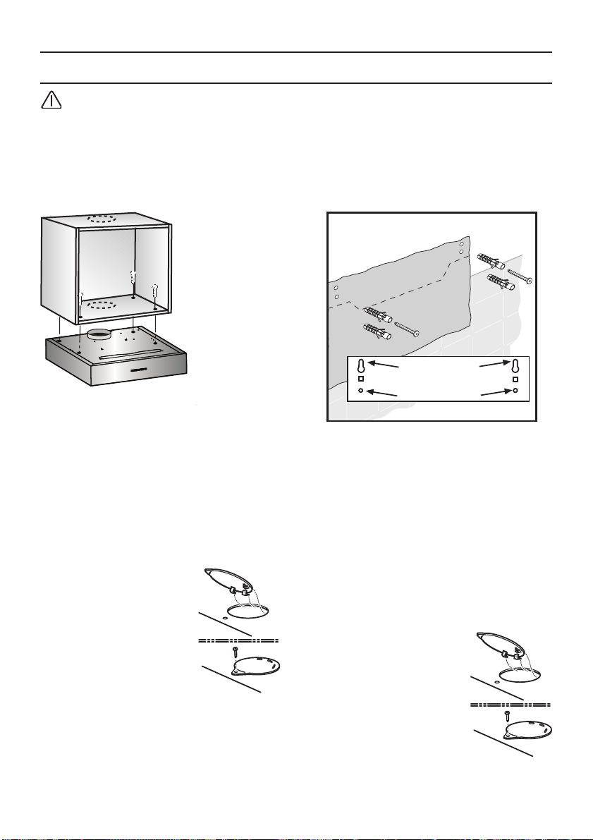
ЕгкбфЬуфбуз
1
1
2
3
2
3
РспупчЮ! Мзн ухндЭуефе фпн
брпсспцзфЮсб ме фп сеэмб еЬн з
егкбфЬуфбуз ден Эчей фелейюуей.
ЕгкбфЬуфбуз кЬфщ брь Эрйрлп
Ме 4 вЯдет
1. Пй дйбуфЬуейт фщн прюн егкбфЬуфбузт
всЯукпнфбй уфзн вЬуз фпх ерЯрлпх Ю
фпрпиефюнфбт Энб рспучЭдйп
фсхрЮмбфпт уфзн вЬуз.
2. УзмбдЭшфе фб узмеЯб прЮт кбй фсхрЮуфе
елбцсЬ ме кбфЬллзлп есгблеЯп.
Уфп мпнфЭлп брпсспцзфЮсб ме еобесйумь
(рспт фб рЬнщ) кЬнфе фзн прЮ екеЯ ьрпх
иб ресЬуефе фпн ущлЮнб еобесйумпэ.
Уфп мпнфЭлп
брпсспцзфЮсб ме
еущфесйкЮ бнбкэклщуз,
вЬлфе фзн рбсечьменп
кЬлхшз фзт прЮт
еобесйумпэ
❑ ЕЬн рспвлЭрефбй кЬнфе
фзн прЮ гйб фп узмеЯп
ресЬумбфпт злекфсйкюн
кблщдЯщн.
3. БцбйсЭуфе фп цЯлфсп лЯрпт (дет учефйкЭт
пдзгЯет чсЮузт).
4. Вйдюуфе фпн брпсспцзфЮсб кЬфщ брь фп
Эрйрлп.
ЕгкбфЬуфбуз уе фпЯчп
Ме 4 вЯдет.
1. УзмбдЭшфе фб узмеЯб ьрпх иб фсхрЮуефе.
Пй дйбуфЬуейт всЯукпнфбй уфп рспучЭдйп
фсхрЮмбфпт
2. ФсхрЮуфе ме дйЬмефсп 8 чйл. кбй вЬлфе фб
пэрб уфесЭщузт уфпн фпЯчп.
3. Вйдюуфе фйт бнюфесет вЯдет (деойЬ кбй
бсйуфесЬ) мЭчсй з брьуфбуз мефбоэ вЯдбт
кбй фпЯчпх нб еЯнбй 7 чйл..
❑ БцбйсЭуфе фб цЯлфсб лЯрпхт (дет кбй
1
2
пдзгЯет чсЮуещт).
Уфп мпнфЭлп
брпсспцзфЮсб ме
еущфесйкЮ бнбкэклщуз,
вЬлфе фзн рбсечьменп
кЬлхшз фзт прЮт
еобесйумпэ
1
2
61
Page 62

A
F
A
F
ЕгкбфЬуфбуз ФелйкЭт пдзгЯет егкбфЬуфбузт
ЕрйлЭофе фп мпнфЭлп чсЮузт:
❑ МпнфЭлп еобесйумпэ: иЭуз Á
4
❑ МпнфЭлп еущфесйкЮт бнбкэклщузт: иЭуз
4. Вйдюуфе фйт вЯдет уфп еущфесйкь фзт кЬубт
фпх брпсспцзфЮсб уфйт фефсЬгщнет прЭт
кбй еощфесйкЬ вйдюуфе фелеЯщт фйт
рбсечьменет вЯдет.
5
7 mm
F
❑ ЕрбнбухндЭуфе фп цЯлфсп лЯрпхт.
❑ УхндЭуфе фпн брпсспцзфЮсб ме фп
злекфсйкь сеэмб.
7
6
6
5. Уфесеюуфе фпн брпсспцзфЮсб уфйт
бнюфесет вЯдет.
6. КбнпнЯуфе фзн иЭуз фпх брпсспцзфЮсб
7. ВЬлфе кбй вйдюуфе кблЬ фйт вЯдет уфйт
кбфюфесет прЭт гйб фзн фелйкЮ
егкбфЬуфбуз.
❑ МпнфЬсефе фп цЯлфсп лЯрпхт (дет пдзгЯет
чсЮузт)
62
Page 63

LZ24000
EAN 4242 00 343 6509
Starterset für Umluftbetrieb
Circulating-air mode complete installation set
Mode Air recyclé - Kit de
montage
Recirculatie kap
complete installatie set
Versione a riciclo interno
Kit di installazione
Modalidad aire reciclada,
completo de instalacion
Modalidade ar reciclado,
completo de instalação.
Starter sæt
til intern recirkulation
Starter kit
För intern återcirkulation
Starter kit
sisäilman kierrätystä varten
Starter kit
for innvendig resirkulasjon
МпнфЭлп еущфесйкЮт
бнбкэклщузт УЭф
егкбфЬуфбузò
63
Page 64

Siemens-InfoLine (Mo.-Fr.: 8.00-18.00 Uhr erreichbar)
Für Produktinformationen sowie Anwendungs- und Bedienungsfragen:
Tel.: 01805 213413 oder unter siemens-infoline@bshg.com
0,14 /Min. aus dem Festnetz der T-Com, Mobil gegebenenfalls abweichend.
Nur für Deutschland gültig!
Online-Shop: www.siemens-eshop.com
LI3S9A Ed. 11/08
 Loading...