

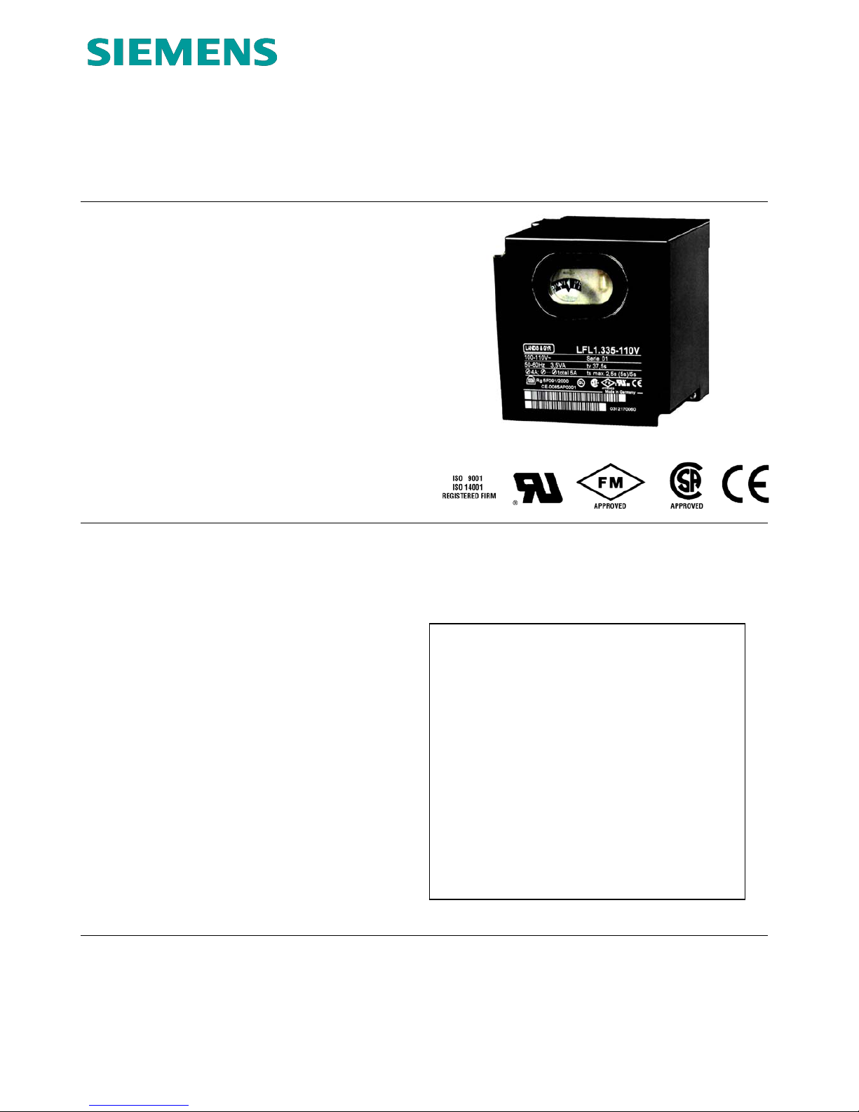
Siemens LFL Series, LFL1.133-110V, LFL1.333-110V, LFL1.335-110V, LFL1.635-110V Technical Instructions
Page 1
Technical Instructions
Document No. 7451US
LFL...
Rev. 2 November 15, 2004
LFL Series
Burner Flame Safeguard Control
The LFL… is a compact electro-mechanical
primary flame safeguard control designed to
provide burner sequencing, automatic ignition and continuous flame monitoring fo
r
gas, oil, and dual fuel, single burner applications.
The LFL… is applicable for on-off, multistage or modulating burners. The LFL… is
designed for direct main burner ignition,
intermittent or interrupted pilot operation.
The LFL… integrates the flame amplifier,
purge timer and sequencer in a single control. Flame supervision is accomplished
using UV sensor or flame rod detection.
Features
• Primary flame safeguard control
• Visual sequence indication
• Optional combustion air blower control
• Optional postpurge
• Preignition interlock
• Continuous flame monitoring,
including extraneous light detection
• UV sensor functional test
• Proven air switch function
• Proven high fire purge interlock
• Proven low fire ignition interlock
• Direct main burner ignition,
intermittent or interrupted pilot operation
• Integrated flame amplifier
• UV sensor or flame rod detector
• Lockout alarm terminal
• Local and optional remote reset
• Burner off – economy position
(fully closed air damper interlock)
• Unit fuse and spare fuse provided
Contents
Control Interface .................................................2
Installation...........................................................2
Ordering information...........................................3
Wiring base.........................................................3
Specifications .....................................................4
Specifications continued.....................................5
Description of oper controls ................................6
Ladder diagram external connections.................7
Sequence Dial OPERATION ..............................8
Sequence Dial FAULT and LOCKOUT...............9
Sequence Chart................................................10
Dimensions.......................................................11
11.15.2004
Siemens Building Technologies
HVAC Products
Page 2
Control interface
2/12
Siemens Building Technologies HVAC Products
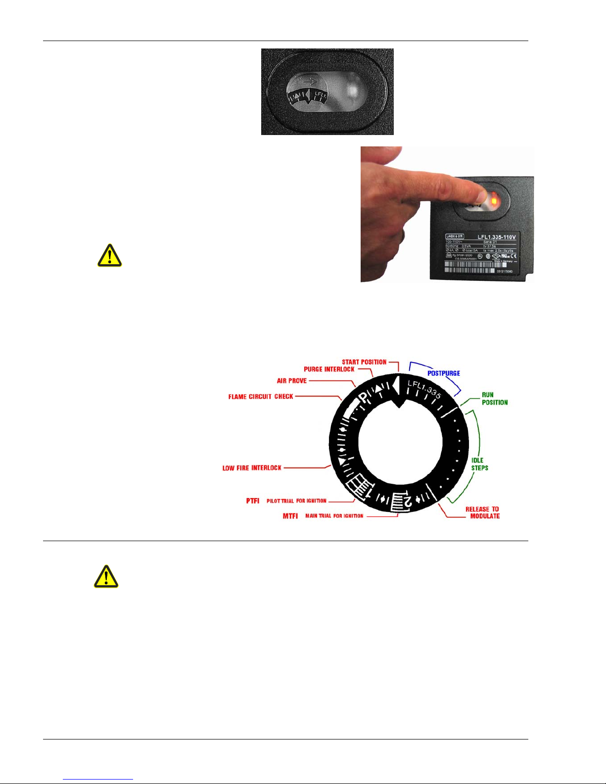
Indicator dial visible
through front window
Lockout indicator light
visible through front
window
The LFL… reset button
is integrated with the front window.
During a lockout condition,
pressing the window resets the LFL...
Pressing
* the window or remote reset
during normal operation will lockout the LFL…
*Do not hold reset button for more than
10 seconds! (Local or remote) , exceeding
10 seconds will damage control !
Manually press the lockout reset button.
Do NOT use any tools or pointed objects.
Indicator dial provides symbolic information about the program sequence, the type of fault,
and the point in the sequence where the fault occurred.
The LFL…
sequence is
fixed and
cannot be
manually
manipulated.
Installation
• All installation and commissioning work must be performed by qualified personnel.
• The LFL… must be mounted in an electrical enclosure, typically in the control panel.
• All wiring must comply with applicable electrical codes standards and regulations.
• Before performing any wiring to the LFL…, remove and isolate all power.
• High voltage AC wiring must not be installed in the same conduit
as the flame detector wiring.
• Maximum 10 A slow external fuse is required.
• The LFL is not adversely affected by electromagnetic resonance.
• Ground the LFL… wiring base.
• Do not open or modify the LFL...
• When UV flame supervision is used, other sources of radiation, such as halogen
lamps, welding equipment, ignition sparks can produce erroneous flame signals.
11.15.2004
Page 3

Ordering Information
Table 1 Product Numbers
110 Vac 50/60 Hz *
LFL1.133-110V LFL1.333-110V LFL1.335-110V LFL1.635-110V
220 Vac 50/60 Hz *
LFL1.133 LFL1.335 LFL1.635
Timing description
Pre-purge time 7.5 sec 26 sec 31 sec 55 sec
Pilot trial for ignition (PTFI) 2.5 sec 4 sec 4 sec
Main trial for ignition (MTFI) 2.5 sec 4 sec
Interval from the beginning of MTFI
until release to modulation
2.5 sec 10 sec 10.5 sec
Post purge time 12 sec 15 sec 12 sec
Flame failure response time (FFRT) 1 sec
*All times listed above are for 60 Hz operation. (Times for 50 Hz operation will be 20% longer.)
Description Product Number
LFL Control unit Refer to Table 1 above
(without wiring base)
Wiring base AGM410490550
Flame sensor
UV (shown) QRA 4.U
forward looking 3/4” NPT
UV Refer to
QRA2… , QRA10 … Technical Instruction 7712
Flame rod By others
Wiring Base
The wiring base provides the following:
• 24 Terminals ______________
• 3 Ground connections __________________--
• 3 Neutral connections,
connected to terminal 2
3/12
Siemens Building Technologies CC1N7451en
HVAC Products 11.15.2004
Page 4

Specifications
Supply voltage
100 Vac –15 % ... 110 Vac +10 % 50/60 Hz ±6 %
220 Vac –15 % ... 240 Vac +10 % 50/60 Hz ±6 %
Internal fuse 6.3 A (slow)
External fuse Maximum 10 A (slow)
Weight – LFL 2.2 lb
Weight – Wiring base 0.25 lb
Power consumption 3.5 VA
Mounting orientation No restrictions
General
Terminal 1 Line Maximum 5 A total load
Terminal 2 Neutral N/A
Terminal 3 Alarm 1 A pilot duty
Terminals 4 to 5 Limit string N/A
Terminals 6 and 7 Combustion Air
Blower
Motor 4 FLA, 24 LRA or 1.6 A pilot duty
Terminals 8, 9, 10, 11 Damper actuator N/A
Terminals 12, 13, 14 Air flow interlock N/A
Terminal 16 Ignition transformer 4 A
Terminal 17 Pilot fuel valve Motor 4 FLA, 24 LRA or 1.6 A pilot duty
Terminal 18 Main fuel valve Motor 4 FLA, 24 LRA or 1.6 A pilot duty
Terminal 19 Main fuel valve Motor 4 FLA, 24 LRA or 1.6 A pilot duty
Terminal 20 Damper actuator N/A
Terminal ratings
110V
UL File: MH26134 Standard: UL372
CSA Certificate: 1370843 Standard: CAN/CSA-C22.2 No 199-M89
FM File: J.I. 3003560 Standard: FM7610
110V & 220V
CE File: CE-0085AP0001 Standard: DIN EN 298
FCC Compliant Part 15 Class B - Emissions
Approvals
Vibration 0.5G Environment
Operation temperature range -5...+140 °F < 95 % relative humidity
Storage temperature range -58...+140 °F < 95 % relative humidity
Condensation, formation of ice and ingress
of water are not permitted!
Environmental
ratings
4/12
Siemens Building Technologies HVAC Products
11.15.2004
Page 5
Specifications continued…
Voltage – during burner operation
Voltage – during start-up phase (flame circuit check)
330 Vac ±10 %
380 Vac ±10 %
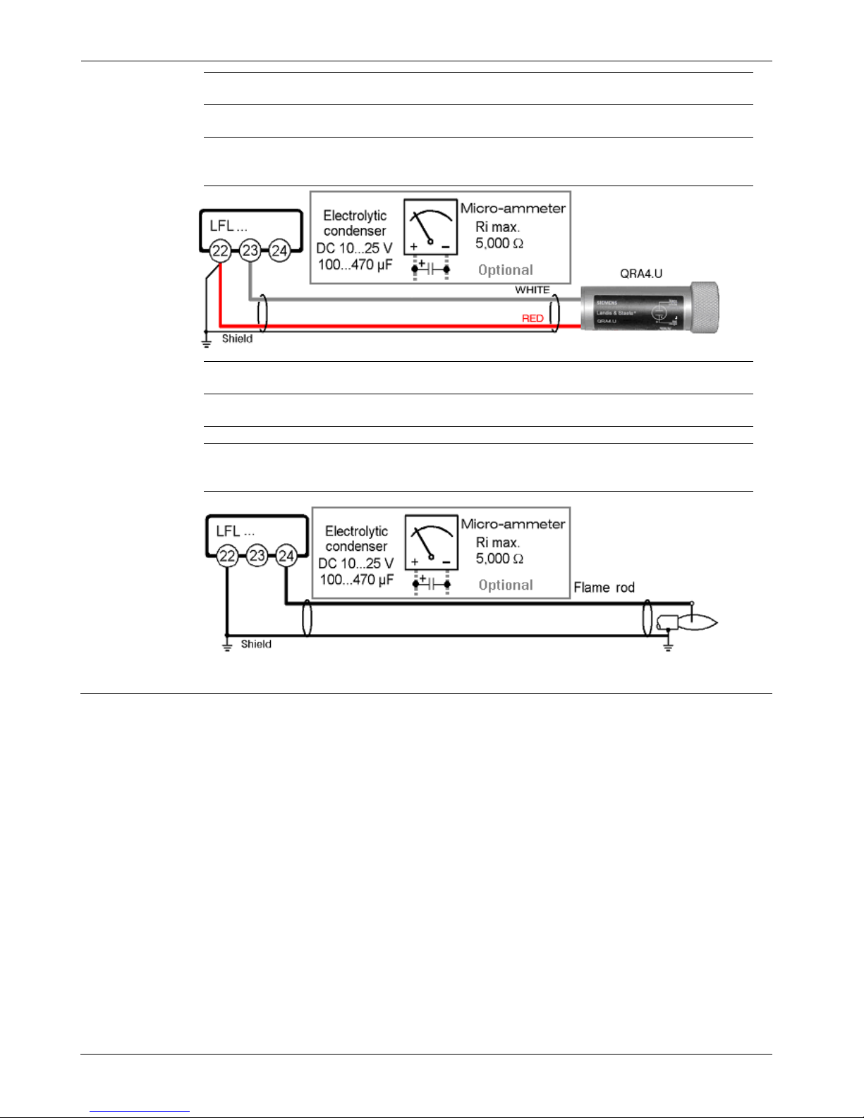
Required minimum UV sensor signal
Typical UV sensor signal measurement
70 µA
100-450 µA
Length of detector cable (run in a separate conduit from all other wiring)
- Unshielded wire
- Shielded cable, shield grounded to terminal 22
max. 300 ft
max. 600 ft
Flame
supervision
with
UV sensor
QRA...
Voltage at the flame rod – during burner operation
Voltage at the flame rod – during start-up phase (flame circuit check)
330 Vac ±10 %
380 Vac ±10 %
Required minimum flame rod signal
Typical flame signal measurement
6 µA
20-100 µA
Short-circuit current max. 0.5 mA
Length of detector cable (run in a separate conduit from all other wiring)
- Unshielded wire
- Shielded cable, shield grounded to terminal 22
max. 250 ft
max. 500 ft
Flame
supervision
with
Flame rod
Electrical connection notes for flame supervision
• It is important to minimize electrical disturbance and signal loss.
• Run flame signal wiring separate from all other wiring
• Observe the length of detector cable as indicated above
• The flame rod does not provide protection from electric shock
• Locate the ignition electrode(s) and flame rod such that the ignition spark cannot arc to the
flame rod (risk of electrical overload and damage to flame supervision circuit)
• When using the QRA..., grounding of terminal 22 is required
• Multiple UV sensors QRA... and/or flame rods can be connected in parallel
• If separate flame sensors are used for pilot and main flame supervision,
an interrupted pilot must be utilized
5/12
Siemens Building Technologies CC1N7451en
HVAC Products 11.15.2004
Page 6

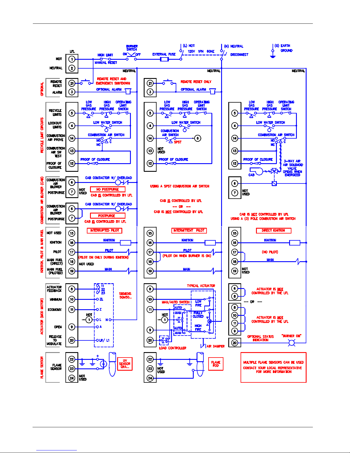
Description of operating controls and their functions
LFL input (1) HOT and LFL input (2) NEUTRAL are used for control power,
Powe
r
Reset and Alarm
LFL output (3) ALARM, for alarm indication
LFL input (21) RESET, as show for reset and/or remote shutdown
Pressure or temperature activated, the operating limit switch (OLS),
Operating limit
OLS
Closes, for burner start-up sequence to begin, and Opens, for a burner controlled shutdown
Pressure, temperature, or level activated, limit switches examples include:
Limit switches
LGP
HGP
LWS
High Limit
Low gas pressure (LGP) opens on low gas pressure
High gas pressure (HGP) opens on high gas pressure
Low water switch (LWS) opens on low water
These limit and are considered either to be recycle or non-recycle, (manual reset),
and are connected between; LFL output (5) RECYCLE and LFL input (4) RECYCLE
Recycle limit switches are used when it is desireable to stop the burner when the switch opens,
and restart it again, automatically, when the switch closes again.
Non-recycle limit switches are used when it is desireable to lockout the burner when the switch
opens and prevent if from automatically restarting again. These switches must be manually reset,
on the switch itself, as well as require you to push the reset button on the LFL to allow a new startup sequence.
The High Limit switch is almost always a non-recycle limit switch, and is usually connected to;
LFL input (1) HOT
NFPA 85, CSD-1 and UL795 require the HGP, LGP to cause a shutdown and be manually reset.
Most burner / boiler insurance codes also require a LWS.
The fuel proof of closure (POC) switch is integral to the fuel valve and activated by the valve
mechanics. The POC prevents a burner start-up if the fuel valve is not in the proved close position.
Fuel proof of closure
POC
LFL input (12) POC, is provided for this purpose. Note -This is a ‘Precondition for Startup’ and
must be powered to start a sequence.
Combustion air blowe
r
CAB
The combustion air blower (CAB) provides combustion air to the burner. Not all installations require the LFL to control the CAB. The LFL provides terminals for two options:
LFL output (7) M2, powered after a 2 sec delay, and continues through postpurge.
LFL output (6) M1, powered immediately, and stops prior to postpurge.
The combustion air switch (CAS) is used to prove that combustion air is being provided. Most
burner / boiler insurance codes require a CAS.
Combustion air switch
CAS
LFL input (14) COMBUSTION AIR PROVE, is connected to the normally open (NO) terminal
of the CAS, and closes when air pressure is present.
LFL input (13) COMBUSTION AIR TEST SW, is connected to the normally closed (NC) terminal of the CAS, to make sure the contacts have not welded.
The LFL provides options for; interrupted pilot, intermittent pilot, and direct ignition as follows;
LFL output (16) IGNITION, for the ignition transformer
Ignition
LFL output (17) PILOT, for interrupted (pilot on only during ignition), or
for intermittent (pilot on when burner is on)
LFL output (18) MAIN DIR IGN, for the main fuel valve on direct ignition
LFL output (19) MAIN PILOT, for the main fuel valve on piloted ignition
High fire purge interlock
OPEN
Generally, an actuator position switch, or a differential pressure switch, that is used to prove the
actuator is at the high fire position. Some codes require the high fire position (open) be proved
during prepurge.
LFL output (9) OPEN, is provided to drive the actuator to this position. *See Note below
This switch is also, generally, an actuator position switch, that is used to prove the actuator is at
the low position. Some codes require the low fire (minimum) position be proved during ignition.
Low fire start interlock
MINIMUM
LFL output (10) MINIMUM, is provided to drive the actuator to this position. *See Note below
This switch is as well, generally another actuator position switch that proves it is at the fully
closed (economy) position. This position is desired following post purge to minimize heat losses.
Fully closed
ECONOMY
LFL output (11) ECONOMY, is provided to drive the actuator to this position. *See Note below
*Note LFL input (8) FEEDBACK, is provided to confirm each of these positions.
LFL output (20) RELEASE, enables an external load controlled and/or to indicate “Burner On“
Release to modulate
Flame sensor in
p
ut
LFL inputs (22) (23) (24) FLAME can be used for a UV sensor or flame rod
6/12
Siemens Building Technologies HVAC Products
11.15.2004
Page 7
Wiring Diagram
7/12
Siemens Building Technologies CC1N7451en
HVAC Products 11.15.2004
Page 8
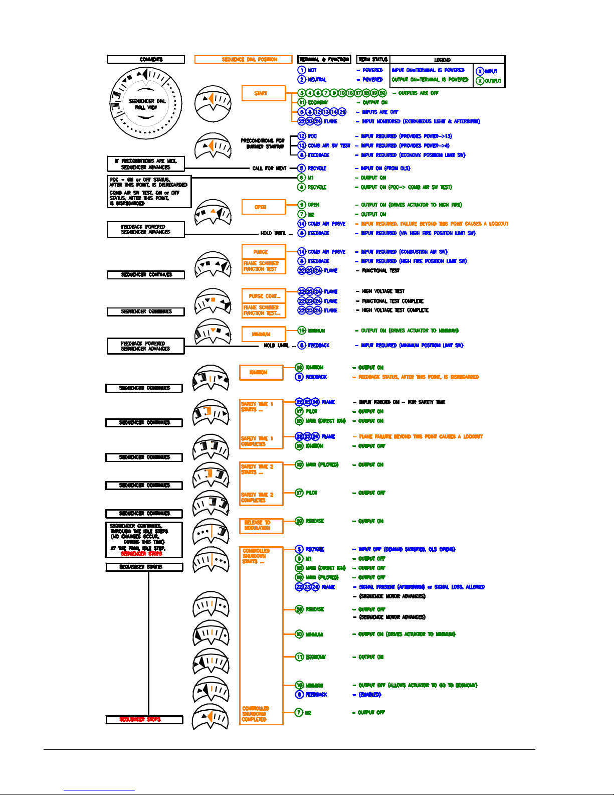
Sequence dial – OPERATION
2
1
P
P
P
P
P
P
P
8/12
Siemens Building Technologies HVAC Products
1
1
2
1
P
2
1
1
2
2
11.15.2004
Page 9
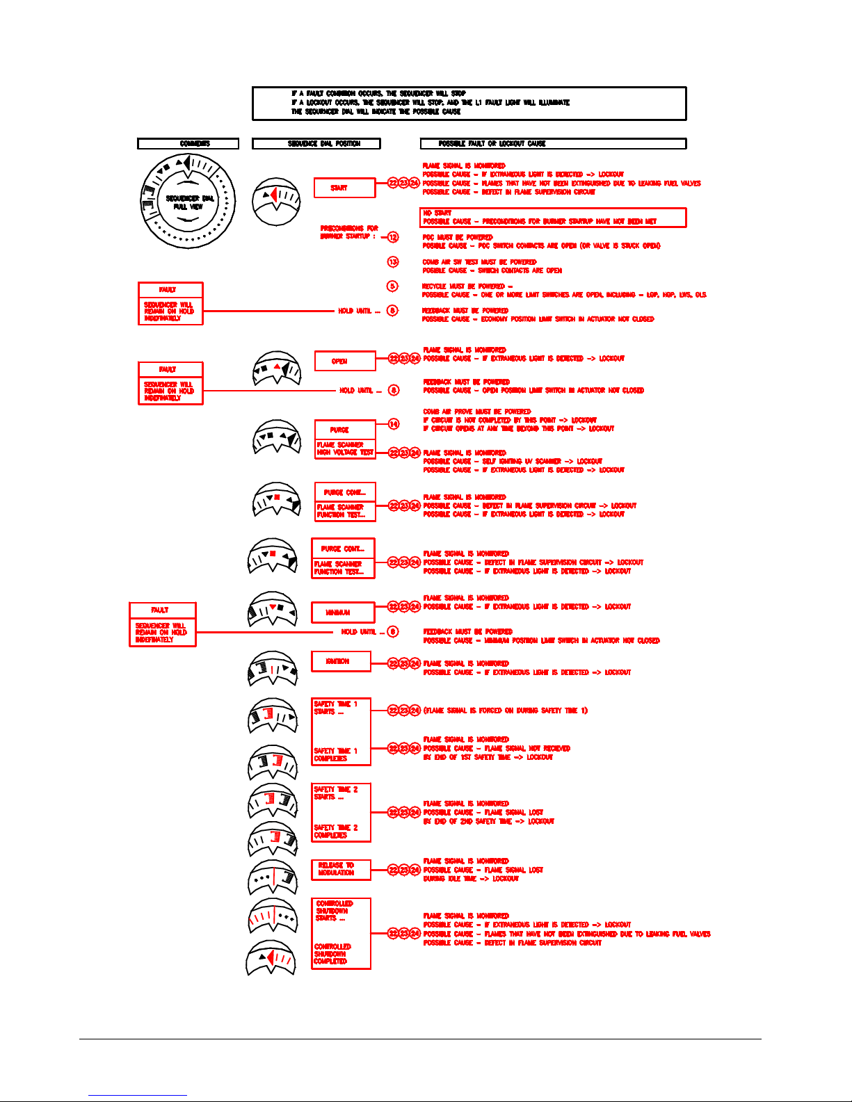
Sequence dial – FAULT and LOCKOUT indication
1
P
2
P
P
P
P
2
P
1
2
1
P
P
1
2
2
1
1
9/12
Siemens Building Technologies CC1N7451en
HVAC Products 11.15.2004
Page 10
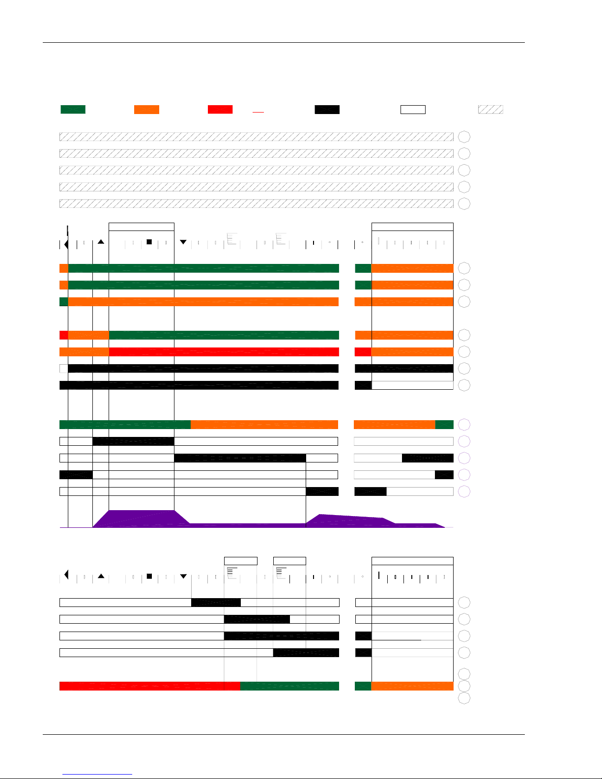
Program Sequence
ECONOMY (FULLY CLOSED
)
CLOSE (MINIMUM)
MAIN (DIRECT IGNITION)
MAIN (PILOTED)
COMBUSTION AIR BLOWE
R
COMBUSTION AIR SW TEST
COMBUSTION AIR PROVE
RECYCLE LIMITS
LOCKOUT LIMITS
POWER (NEUTRAL)
POWER (HOT)
ACTUATOR FEEDBACK
POC (PROOF OF CLOSURE)
RELEASE TO MOD
NOT USED
FLAME SIGNAL
COMBUSTION AIR BLOWE
R
CLOSE (MINIMUM)
ECONOMY (FULLY CLOSED)
P
OPEN
Modulation
1
2
...
...
...
...
...
...
MTFI
PTFI
IDLE
...
...
...
...
19
22
23
24
18
16
17
PILOT
IGNITION
POSTPURGE
ACTUATOR
20
11
10
9
OPEN
PROGRAM SEQUENCE CHART
TART
PREPURGE
P
RequiredINPUT AllowedINPUT
1
...
...
...
...
...
...
...
1
2
...
...
5
8
6
7
12
13
14
POSTPURGE
4
15
21
3
2
RESET
ALARM
Output ON (Powered)
NOT AllowedINPUT Output OFF N/A
10/12
Siemens Building Technologies HVAC Products
11.15.2004
Page 11
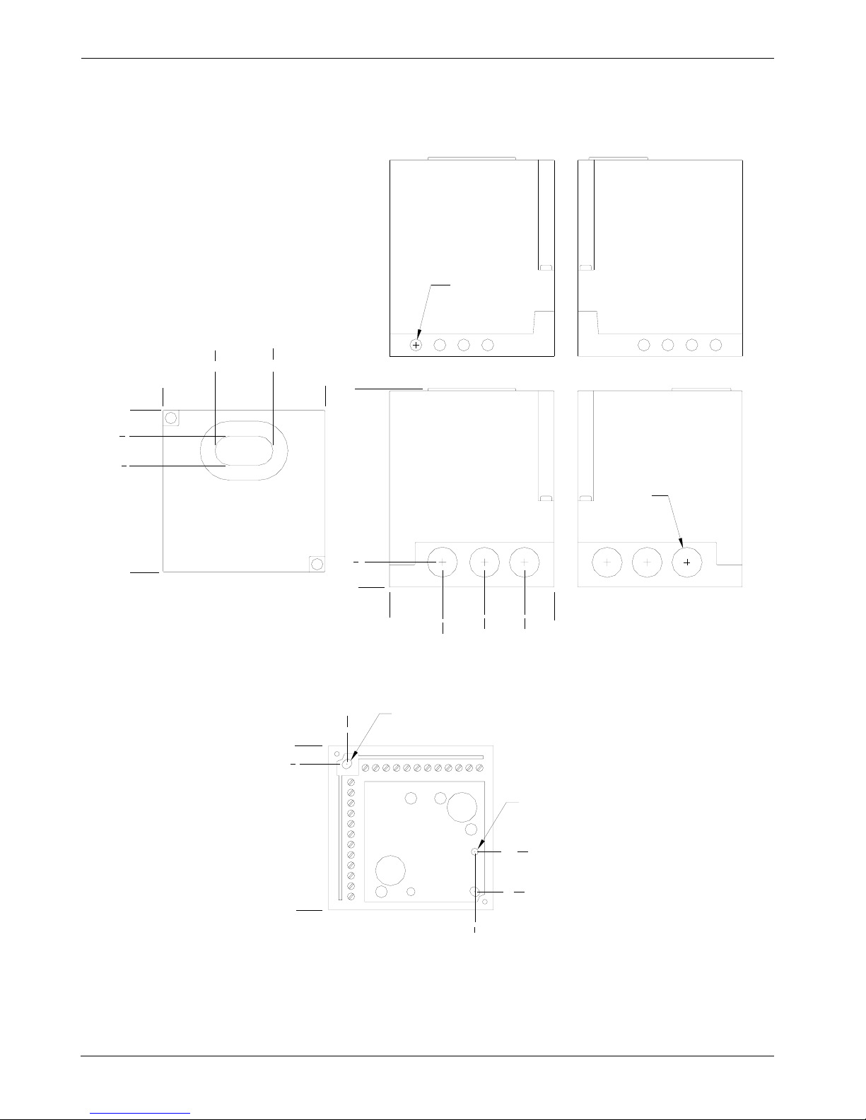
Dimensions
Dimensions in inches
2 Places
(5.2 x 6.4 mm)
3/16 x 1/4
7
16
4
3
5
8
0
3
5
8
7
16
1
7
16
4.4 mm)Ø(
3/16Ø
Ground
Ø 5/16
(Ø 7.5 mm)
5
5
8
0
4
1
3
8
5
8
0
4
0
1
5
16
2
11
16
Ø 3/4
4
0
1
5
16
3
5
16
2
5
16
Top
Right
Front
LeftBack
11/12
Siemens Building Technologies CC1N7451en
HVAC Products 11.15.2004
Page 12
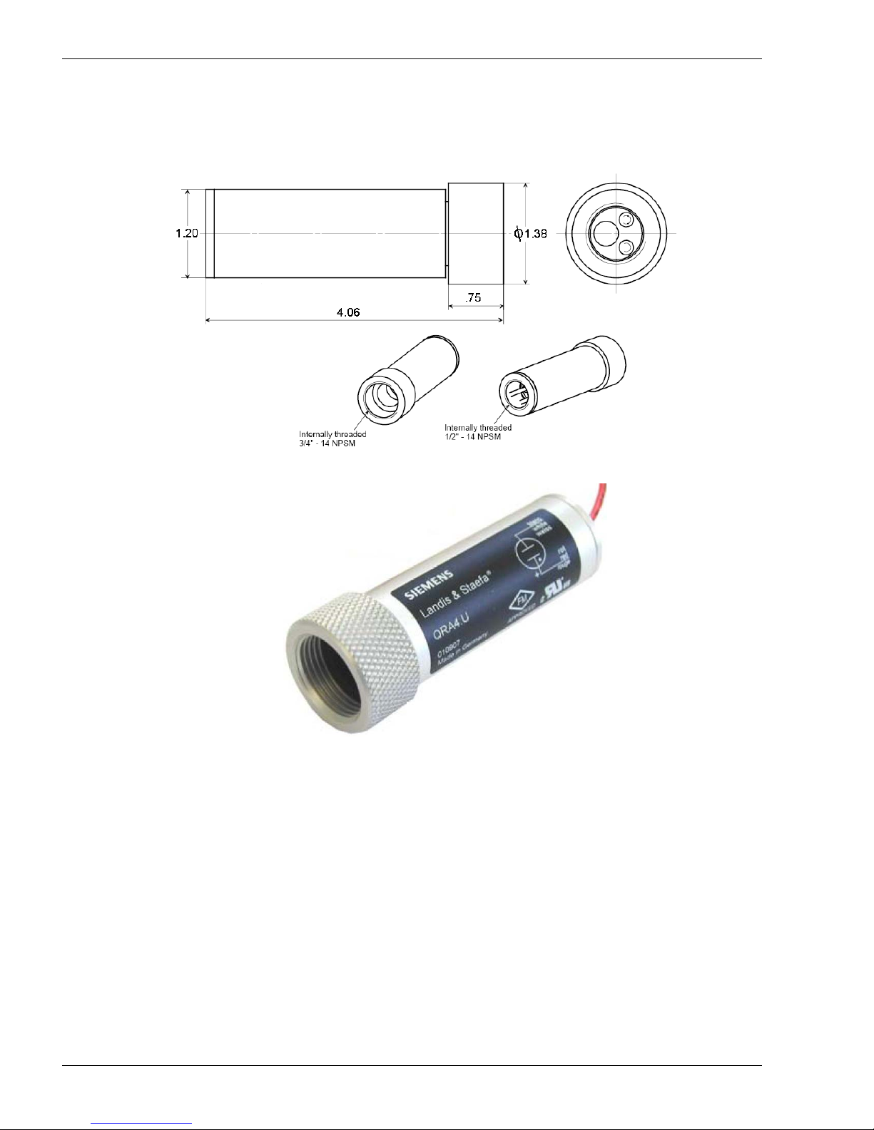
Dimensions QRA4.U
Dimensions in inches
12/12
Siemens Building Technologies HVAC Products
11.15.2004
 Loading...