

Page 1
Instruction Manual January 2003
sitrans
LC 500
Page 2

Safety Guidelines
Warning notices must be observed to ensure personal safety as well as that of others, and to
protect the product and the connected equipment. These warning notices are accompanied
by a clarification of the level of caution to be observed.
Qualified Personnel
This device/system may only be set up and operated in conjunction with this manual.
Qualified personnel are only authorized to install and operate this equipment in accordance
with established safety practices and standards.
Warning: This product can only function properly and safely if it is correctly transported,
stored, installed, set up, operated, and maintained.
Note: Always use product in accordance with specifications.
Copyright Siemens Milltronics Process
Disclaimer of Liability
Instruments Inc. 2003. All Rights Reserved
This document is available in bound version and in
electronic version. We encourage users to
purchase authorized bound manuals, or to view
electronic versions as designed and authored by
Siemens Milltronics Process Instruments Inc.
Siemens Milltronics Process Instruments Inc. will
not be responsible for the contents of partial or
whole reproductions of either bound or electronic
versions.
MILLTRONICS®is a registered trademark of Siemens Milltronics Process Instruments Inc.
Contact SMPI Techni cal Publications at th e following address:
Technical Publications
Siemens Milltronics Process Instruments Inc.
1954 Technology Drive, P.O. Box 4225
Peterborough, Ontario, Canada, K9J 7B1
Email: techpubs@siemens-milltronics.com
While we have verified the contents of
this manual for agreement with the
instrumentation described, variations
remain possible. Thus we cannot
guarantee full agreement. The
contents of this manual are regularly
reviewed and corrections are included
in subsequent editions. We welcome
all suggestions for improvement.
Technical data subject to change.
For the library of SMPI instruction manuals, visit our Web site: www.siemens-milltronics.com
© Siemens Milltronics Process Instruments Inc. 2003
Page 3

Table of Contents
SITRANS LC 500 ............................. .....................................................................................1
Applications ....................................................................................................................................1
Safety Notes .............................................................................................................................................2
Safety marking symbols ..............................................................................................................2
The Manual .....................................................................................................................................2
Abbreviations and Identifications .............................................................................................3
Technical Specifications: SITRANS LC 500 ...................................................................4
SITRANS LC 500: Transmitter ............................................................................................8
Operating Principles ...............................................................................................................................8
The SITRANS LC 500 variable frequency oscillator .......................................................................8
The SITRANS LC 500 electrode .........................................................................................................10
Application: SITRANS LC 500 ...................................................................................................12
Level Measurement ....................................................................................................................13
Interface Measurement .............................................................................................................14
Switch action ................................................................................................................................14
Fault Signalling .............................................................................................................................15
SITRANS LC 500: Probe Configuration ..........................................................................16
SITRANS LC 500 Electrode (Probe) Characteristics .....................................................................16
Electrode Assembly ..............................................................................................................................17
Process Connections ..................................................................................................................17
Seal Types .....................................................................................................................................17
Process Connection and Seal Configuration of SITRANS LC 500 ..................................17
Pressure and Temperature Considerations ..........................................................................18
Non-standard applications .......................................................................................................19
Table of Contents
SITRANS LC 500: Installation ....... ...................................................................................20
Handling Electrodes ..............................................................................................................................20
Mounting Instructions ..........................................................................................................................21
Protection for solid-state switch .............................................................................................21
Process Cautions .......................................................................................................................21
SITRANS LC 500: Standard Level Version .............................................................................22
Interconnection: SITRANS LC 500 ..................................... ............................................23
Wiring .......................................................................................................................................................23
Supply .............................................................................................................................................23
Cable ...............................................................................................................................................24
Selecting the correct instrumentation cable ......................................................................24
Terminals .................................................................................................................................................26
Connecting SITRANS LC 500 ..............................................................................................................26
Connection Diagram .................................................................................................................26
Protection for solid-state switch .............................................................................................27
Grounding instructions ..............................................................................................................27
Grounding Examples: SITRANS LC 500 ...........................................................................................28
System Grounding (referencing) .............................................................................................28
Metal Tanks ................................................................................................................................28
i
Page 4

Cathodically Protected Metal Tanks ....................................................................................29
Non-Conductive Tanks ............................................................................................................29
Safety Grounding .........................................................................................................................30
Communications ....................................................................................................................................32
Typical PLC configuration with HART ..................................................................................32
Diagnostics .............................................................................................................................................32
Table of Contents
Applications for Solid-state Output ..................................................................................................33
Switch Protection (Diode) .........................................................................................................34
Factory Settings .....................................................................................................................................34
Settings: .......................................................................................................................................34
The SITRANS LC 500 User Interface .............................................................................36
The LCD (display) ...................................................................................................................................36
How to access the data: ......................................................................................................................37
Menu Levels 00 to 0F and 10 to 1F ..........................................................................................37
The rotary switch ...................................................................................................................................38
The push-buttons ........................................................................................................................38
Access to a menu item: ............................................................................................................38
Adjusting the value .....................................................................................................................38
Transmitter Variables ...........................................................................................................................39
Start-up: SITRANS LC 500 ...................................................................... .........................40
Quick Start ..............................................................................................................................................40
Menu levels 0 and 1 ..............................................................................................................................42
Start up using push-button calibration: (overview) ......................................................................42
Calibration using push-button adjustment ......................................................................................43
Calibration using HART ........................................................................................................................46
Maintenance ........ ........ ...... ...... ....... ...... ........ ...... ....... ...... ........ ...... ...... ....... ...... ........ .........50
Test function ...........................................................................................................................................50
Inspections ....................................................................................................................................50
Troubleshooting: SITRANS LC 500 .. ...............................................................................52
Error Messages and Error Codes ...................................................................................53
Error Messages (push-button operation) .......................................................................................53
Error Codes (HART) ...............................................................................................................................53
Appendix A: Menu Groups ..............................................................................................54
Menu Items .............................................................................................................................................55
Transmitter: Variable Settings: menu level 0......................................................................................... 55
Transmitter Variable Values: menu level 0............................................................................................. 59
Analog Output Signalling (proportional or 2-state): menu level 0..................................................... 62
Analog Signalling Mode (2-state): menu level 0................................................................................... 64
Digital Output Signalling (solid-state output): menu level 1 ............................................................... 67
Miscellaneous............................................................................................................................................... 72
Appendix B: LCD display examples ..............................................................................74
LCD: alphanumeric display examples ....................................................................................74
ii
Page 5

Appendix C: HART Documentat ion ...............................................................................75
HART Communications for the SITRANS LC 500 ..........................................................................75
HART Device Descriptor (DD) ..................................................................................................75
Simatic Process Device Manager (PDM) .............................................................................75
HART information ..................................................................................................................................75
Expanded Device Type Code: ................................................................................................75
Physical Layer Information .....................................................................................................75
SITRANS LC 500 DD Menu/Variable Organization .......................................................................76
HART Response Code Information ...................................................................................................77
Bit #7: Field Device Malfunction ............................................................................................77
Bit #6: Configuration Changed ...............................................................................................77
Bit #5: Cold Start ........................................................................................................................77
Bit #4: Extended Status Available .........................................................................................77
Bit #3: Output Current Fixed ....................................................................................................77
Bit #2: Primary Variable Analog Output Saturated ...........................................................77
Bit #0: Primary Variable Out of Limits ...................................................................................77
HART Conformance and Command Class ......................................................................................78
General Transmitter Information .......................................................................................................79
Damping information ................................................................................................................79
Non-volatile Memory Data Storage .....................................................................................79
MultiDrop operation .................................................................................................................80
Burst mode .................................................................................................................................80
Units conversions .....................................................................................................................80
Additional Universal Command Specifications .............................................................................80
Appendix D: Block Diagram, and Correlation table, mA to % ................................81
Correlation Table: 0% - 100% to 4-20 mA or 20-4 mA ...................................................................82
Table of Contents
Appendix E: SITRANS LC 500, alternate versions and application details ...........83
Standard Version ...................................................................................................................................83
Standard Version S-Series, Threaded ..................................................................................83
Standard Version S-Series, Threaded ...................................................................................84
Standard Version S-Series, Welded and Machined Flanged Versions .........................85
Standard Version D-Series, Machined Flange ....................................................................86
Interface Version ...................................................................................................................................88
Sanitary Version ....................................................................................................................................89
Flanges .....................................................................................................................................................90
Flange Standards ........................................................................................................................90
Applications Examples .........................................................................................................................91
Generic Application Calculations ............................................................................................91
Application: level indicator and solid-state switch output ................................................93
Application: Analog fault signalling (2-state output) ..........................................................94
iii
Page 6

Appendix F: Approvals .....................................................................................................96
CE Certificate ................................................................................................................................96
CE Certificate ................................................................................................................................97
Instrument label: SITRANS LC 500 ...................................................................................................98
KEMA certificate and schedules .......................................................................................................99
Certificates and Approvals .............................................................................................................. 107
Table of Contents
NAMUR recommendation NE 43 .......................................................................................... 107
Control Drawing FM/CSA Approval ............................................................................................... 108
SITRANS LC 500 ................................................................................................................................. 108
Glossary ............ ................................. ............................... ............................... .................109
Index .................. .............. ............ ............. ............ ............. ............ ............... ............ ......... 111
Quick Reference: SITRANS LC 500 .............................................................................. 113
Quick Start ............................................................................................................................................113
iv
Page 7

SITRANS LC 500
SITRANS LC 500 is a high performance 2-wire capacitance instrument for continuous level
and interface measurement in extreme or critical conditions. It uses a unique frequencybased measurement system and patented Active-Shield technology to deliver highly
accurate, repeatable results. The measurement is unaffected by moisture, vapors, foam,
temperature and pressure variations, or material build-up around the mounting glands.
SITRANS LC 500 combines a sophisticated, easy-to-adjust transmitter (MSP-2002-2) with a
measurement electrode and process seal selected from a range of options
variety of applications. The advanced electronics and integrated local display provide for
one-step calibration without interrupting the process, and the probe shield design eliminates
the need for frequent recalibration.
SITRANS LC 500 can be used as a level controller, by connecting the mA output and/or the
solid-state switch to a relay, and activating a pump via an auxiliary power circuit.
The SITRANS LC 500 is equipped with:
• Smart 2-wire transmitter
• Remote adjustable commissioning / control capabilities via HART
• Analog (2-wire) 4 to 20mA / 20 to 4 mA output
• Solid-state and Current detection (4 or 20 mA / 20 or 4 mA, two-state
functionality)
• Adjustable hystereses on/off for solid-state output and for current signal
• Damping functionality
• Signal current (measurement/detection) according to NAMUR NE 43
• Integrated local display for commissioning and services activities
• Full range of local/remote diagnostic facilities
• Pre-detection of trip point for high safety requirements
• Polarity-insensitive current loop
• Integrated zener safety barrier for Intrinsically Safe applications
1
, to suit a wide
2
Introduction
Applications
• General Purpose, Dust Ignition Proof, Explosion Proof, and Intrinsically Safe
• A wide range of applications in high pressure and temperature, chemically
aggressive, and other extreme measurement/detection environments
• Liquids, Solids, Quality, and Interface measurement
• Viscous non-conducting and conducting liquids
1.
Customized probe configurations can also be provided.
2.
HART® is a registered trademark of the HART Communications Foundation,
Austin, Texas, USA.
7ML19985GE01 SITRANS LC 500 – INSTRUCTION MANUAL Page 1
Page 8
Safety Notes
Special attention must be paid to warnings and notes highlighted from the rest of the text
by grey boxes.
WARNING: relates to a caution symbol on the product, and means
Introduction
Safety marking symbols
that failure to observe the necessary precautions can result in
death, serious injury, and/or considerable material damage.
WARNING: means that failure to observe the necessary
precautions can result in death, serious injury, and/or considerable
material damage.
CAUTION: means that failure to observe the necessary precautions can
result in considerable material damage.
Note: means important information about the product or that part of the operating
manual.
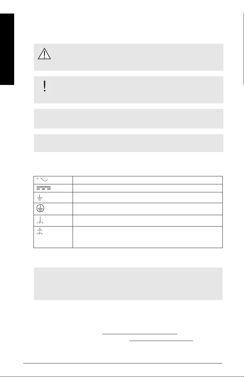
Alternating Current
Direct Current
Earth (ground) Terminal
Protective Conductor Terminal
Frame or Chassis Terminal
Cathodic protection resulting in a potential difference: for example,
between the ground on the instrument and the potential of the vessel
or tank
The Manual
Notes:
• Please follow the installation and operating procedures for a quick, trouble-free
installation and to ensure the maximum accuracy and reliability of your SITRANS LC 500.
• This manual applies to the SITRANS LC 500 only.
This manual will help you set up your SITRANS LC 500 for optimum performance. We
always welcome suggestions and comments about manual content, design, and
accessibility.
Please direct your comments to techpubs@siemens-milltronics.com
library of Siemens Milltronics manuals, go to www.siemens-milltronics.com
Page 2 SITRANS LC 500 – INSTRUCTION MANUAL 7ML19985GE01
. For the complete
Page 9

Abbreviations and Identifications
Short form Long Form Description Units
A/D Analog to Digital
Conformitè Europèene / Factory
CE / FM / CSA
D/A Digital to Analog
DAC Digital Analog Converter
DCS Distributed Control System control room apparatus
ESD Electrostatic Discharge
Ex Explosion Proof safety approval
Exd Flame Proof safety approval
FV Full Vacuum
HART
IS Intrinsically Safe safety approval
LRV Lower Range Value value for 0 % 4 mA
LSL Lower Sensor Limit
µF micro Farads 10
µs micro Seconds 10
PED Pressure Equipment Directive safety approval
pF pico Farads 10
ppm parts per million
PV Primary Variable measured value
Stilling Well
SV Secondary Variable equivalent value
SVLRV
SVURV
TV Transmitter Variable
URV Upper Range Value value for 100% 20 mA
USL Upper Sensor Limit
Mutual / Canadian Standards
Association
Highway Addressable Remote
Trans ducer
Grounded metal tube with
openings
Secondary Variable Lower
Range Value
Secondary Variable Upper
Range Value
safety approval
below which no PV is
anticipated
-6
-6
-12
0% equivalent value
100% equivalent value
above which no PV is
anticipated
Farad
Seconds
Farad
Introduction
7ML19985GE01 SITRANS LC 500 – INSTRUCTION MANUAL Page 3
Page 10

Technical Specifications: SITRANS LC 500
Power
Supply voltage
• maximum: 33 Vdc, (30 Vdc for IS)
• minimum 12 Vdc at 3.6 mA (9.5 Vdc at 22 mA)
Loop current 3.6 to 22 mA / 22 to 3.6 mA (2-wire current loop)
Environmental
Location indoor/outdoor
Altitude 2000 m max.
Specifications
Performance
Ambient temperature
• standard: –40
• ATEX-Explosion Proof –40 oC to 70 oC (–40 oF to 158oF) for T6
Relative humidity suitable for outdoor (Type 4X / NEMA 4X / IP 65
Installation category II
Pollution degree 4
Measurement range
• MSP-2002-2 0 to 3300 pF
Minimum span 3.3 pF
Measurement frequency 420 kHz @ Cx = 0 pF
Accuracy deviation <0.1% of actual measurement value
Non-linearity 0.1% full scale
Repeatability 0.1% actual measurement
Temperature stability 0.15 pF (0pF) or <0.25% (typically <0.1%) of actual
o
C to 85 oC (–40 oF to 185 oF)
–40 oC to 85 oC (–40 oF to 185 oF) for T5 to T1
enclosure)
measurement value, whichever is greater over the full
temperature range of the transmitter
Page 4 SITRANS LC 500 – INSTRUCTION MANUAL 7ML19985GE01
Page 11

Safety • current signalling according to NAMUR NE 43;
3.6 to 22 mA / 22 to 3.6 mA
• probe input ESD protected to 55 kV
• inputs/outputs fully galvanically isolated
• polarity-insensitive current loop
• fully potted
• integrated safety barrier
Diagnostics (Includes • primary variable (PV) out of limits
fault alarm) • system failure measurement circuit
• deviation between A/D and D/A converter
values
•check sum
•watch dog
• self-checking facility
Outputs
• galvanically isolated
• damping range 1 to 10,000
Current loop
• continuous signal 4 to 20 mA / 20 to 4 mA
• 2-state functionality 4 or 20 mA / 20 or 4 mA, on or off
• time delay 1 to 100 sec. activating / de-activating
• adjustable hysteresis (on / off) 0 to 100%, min. 1% of range
Solid-state switch 40 Vdc / 28 Vac / 100 mA at 2 VA max.
• time delay 1 to 100 sec. activating / de-activating
• adjustable hysteresis (on / off) 0 to 100%, min. 1% of range
Specifications
User Interface
Local digital display 4 1/2 digit LCD
Rotary function switch for selecting programmable menu items
• 16 Positions 0 to 9, A to F
Push-buttons: RED (+), BLUE (–) used in conjunction with rotary switch, for
programming menu items
Communications
HART 1 Communication protocol
1.
HART® is a registered trademark of the HART Communications Foundation.
7ML19985GE01 SITRANS LC 500 – INSTRUCTION MANUAL Page 5
Page 12

Electrodes
Specifications
Wetted Parts
Process connections
• threaded connection AISI 316 L stainless steel, 3/4”, 1”, 1-1/4”, 1-1/2”, 2”, NPT,
BSPT, JIS
• flat-faced flanges AISI 316 L stainless steel (optional C 22.8 N, Monel
Hastelloy2 C22, Duplex) ANSI, DIN
3
Probe diameter
• Cable: 9 mm (0.35”)
• Rod: 16 mm (0.63”) or 24 mm (0.95”)
Probe length
• Rod version: up to 3500 mm (138”) with 16 mm (0.63”) diameter probe
up to 5500 mm (216”) with 24 mm (0.95”) diameter probe
• Cable version: 35 m (15 ft.)
Probe insulation PFA, Enamel
4
Probe insulation PFA / Enamel
Threaded connection AISI 316 L stainless steel
5
Flange AISI 316 L stainless steel or Teflon
covered
1
400,
Enclosure (electronic)
• construction aluminum, epoxy-coated; diameter 160 mm (6.3")
• cable entry 2 x 1/2” NPT
• ingress protection Type 4X / NEMA 4X / IP 65
Weight
Depends on configuration.
Example:
model: S-series
rod: PFA insulated, 16 mm (0.63”) dia., 1 m (39.4”) insertion length
weight: approx. 5 kg
1.
Monel® is a registered trademark of the International Nickel Company.
2.
Hastelloy® is a registered trademark of Haynes International Inc.
3.
Please see
4.
Only available as Rod version, max. length 1500 mm (59”), and only for use in
applications where pH ≤ 7.
5.
Teflon® is a registered trademark of Dupont.
Page 6 SITRANS LC 500 – INSTRUCTION MANUAL 7ML19985GE01
Flange Standards
on page 90 for a table showing flange sizes.
Page 13

Process Conditions
Pressure rating
• standard FV (full vacuum) to 200 bar (2920 psi)
• option up to 525 bar (7665 psi)
Temperature rating
• standard –200 °C to 200 °C (–328 °F to 392 °F)
• option up to 400 °C (752 °F)
1
1
Approvals
CE Complies with the requirements of E.C.C. as per EN 55011
and EN 61326
Dust Ignition Proof (DIP) ATEX II 3GD (EEx nA [ib] IIC T4...T6)
FM/CSA: Class I, Div. 2, Gr. A,B,C,D T4
Class II, Div. 1, Gr. E,F,G T4
Class III, Div. 1, Gr. E,F,G T4
Intrinsically Safe (IS) ATEX II 1 G (EEx ia IIC T4...T6)
FM/CSA: Class I, Div. 1, Gr. A,B,C,D T4
Flame-proof/ ATEX II 1/2 GD (EEx d [ia] IIC T6...T1)
Explosion-proof enclosure FM/CSA: Class I, Div. 1, Gr. A,B,C,D T4
Sanitary 3A
Lloyds Register of Shipping Categories ENV1, ENV2, ENV3, ENV5
European Pressure, PED 97 / 23 / EC
Note: See
Appendix F: Approvals
on page 96 for details of certification.
Specifications
1.
Please refer to page 18, Temperature/ Pressure Curve chart, for specific combinations of temperature and pressure.
7ML19985GE01 SITRANS LC 500 – INSTRUCTION MANUAL Page 7
Page 14

SITRANS LC 500: Transmitter
Operating Principles
Capacitance1 measurement operates by forming a variable capacitor resulting from the
installation of a vertical measurement electrode in a vessel or silo. The tank wall usually
forms the reference electrode of the capacitor. Whatever material is sandwiched
between the two electrodes forms the dielectric. This will be composed of the vessel
contents (air, vapor, liquid, solid, or a combination) and, if the measurement electrode is
insulated, the insulating layer (PFA, for example). The dielectric gives a capacitance value
that is proportional to level.
Capacitance is affected by the surface area of the electrodes, the separation distance
between the electrodes, and the dielectric constant of the vessel contents. The dielectric
constant is the measure of a material’s ability to store energy. The relative dielectric
constant of air (vacuum) is 1: all other materials have a higher value.
Note: To preserve linearity of the measurement, both electrodes must be parallel.
(When the vessel contents are conductive, the measurement electrode is insulated
and the interface between the insulating layer and the contents acts as a parallel
reference electrode independent of the tank wall.)
The SITRANS LC 500 variable frequency oscillator
The SITRANS LC 500 probe is equipped with a variable frequency oscillator which
responds to the capacitance: a change in capacitance is registered as a change in
frequency. The relationship between capacitance and frequency is inverse, resulting in
Operation & Application
high resolution and accuracy. The variable frequency maintains a constant relationship to
the reading.
Capacitance measurement in a cylindrical metal tank
In a cylindrical tank, it is possible to determine the initial capacitance in air by factoring in
the length of the probe, diameter of the probe, diameter of the tank, and the relative
dielectric constant of air.
1.
For definitions relating to capacitance, see the glossary, page 109.
Page 8 SITRANS LC 500 – INSTRUCTION MANUAL 7ML19985GE01
Page 15

The formula1 is:
K ε L××
C
--------------------------=
Log D d⁄()
where C = capacitance
K = constant
ε = dielectric constant
L = active measurement length
D = diameter of tank
d = probe diameter.
(For detailed application examples, see page 91.)
The transmitter measures the capacitance of the measurement electrode relative to the
tank wall (reference electrode) and transforms it to a 4-20 mA signal. Any material that
covers the probe will cause an increase in capacitance relative to an uncovered probe
surrounded by air. As the product level rises the capacitance will increase.
Non-conductive or conductive contents
In practice, the SITRANS LC 500 probe is usually insulated. If the vessel contents are nonconductive, the dielectric is composed of the vessel contents and the insulation, and the
separation distance is from the probe to the tank wall. The tank wall is the reference
electrode, and it must be connected to the ground point on the instrument.
dielectric = contents plus insulation (non-conductive contents)
dielectric = insulation (conductive contents)
Operation & Application
probe
dia. (d)
internal
tank wall
internal tank diameter (D)
(insulation)
p ro b e
sleeve
Note: For simplicity, the probe is shown centrally mounted. If it is to be mounted off-
centre, take care to ensure the electrode remains parallel to the tank wall.
If the vessel contents are conductive, the electrode must be insulated. In this case the
dielectric is the insulation layer and the interface between the conductive contents and
the insulating sleeve acts as the reference electrode. This reduces the separation
distance for the filled portion of the tank to the thickness of the insulation. It also creates
a linear reference electrode independent of the tank wall.
1.
This formula applies to a centrally mounted probe: for a probe mounted off-centre, the
formula must be adjusted.
7ML19985GE01 SITRANS LC 500 – INSTRUCTION MANUAL Page 9
Page 16

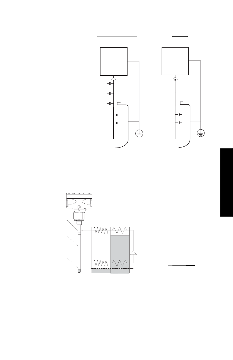
In a non-conductive or irregular tank
Where the vessel contents are non-conductive:
• a reference electrode parallel to the measurement electrode is required
• the reference electrode must be grounded to the instrument
• a stilling well can form the reference electrode.
Where the vessel contents are conductive:
• the interface between the contents and the electrode insulation acts as the
reference electrode
• a connection from the vessel contents to the instrument ground is required
• a stilling well can provide a means of connecting the contents to the instrument
ground.
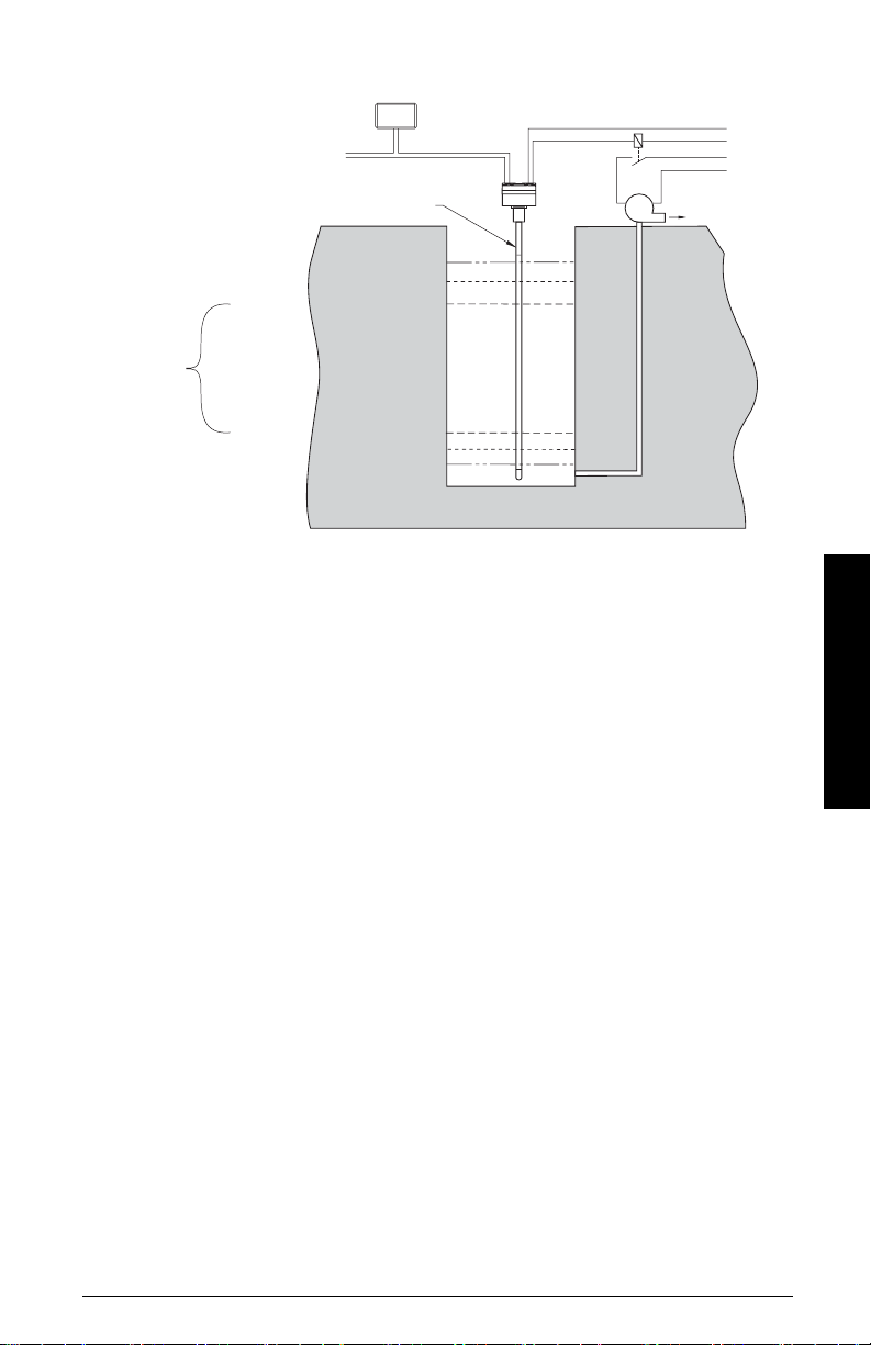
The stilling well
The stilling well is a metal tube concentric with the electrode, with vent openings to
facilitate level equalization. Its diameter is somewhat larger than that of the electrode,
depending on the application. The stilling well can either be integral to the SITRANS LC 500,
or it may be part of the tank
1
.
The SITRANS LC 500 electrode
The SITRANS LC 500 electrode, comprising a measurement section and an active shield
section, is the primary sensor of the system. It supplies the electrical capacitance value
of the measurement section relative to the environment (tank wall or stilling well).
The SITRANS LC 500 patented Active-Shield Technology electrically isolates the
measurement section and prevents any non-measurement capacitance from interfering
with the measurement. (Capacitance changes could result from uncontrolled variations
occurring in the connection cable, process connection, and non-active parts of the
Operation & Application
probe). This results in a better ratio of initial capacitance to total capacitance, resulting in
higher accuracy.
1.
The tank wall, or the stilling well if it is part of the tank, must be grounded.
Page 10 SITRANS LC 50 0 – INSTRUCTION MANUAL 7ML19985GE01
Page 17
R = Ratio between initial
capacitance and total
capacitance
Ca = Initial capacitance (air)
Cm = Capacitance Increase
(product)
C1 = Capacitance connection
point
C2 = Capacitance connection
cable
C3 = Capacitance Process
connection (includes active
part)
Conventional Capacitance
Measurement
R = (C1 + C2 + C3) + Ca
(C1 + C2 + C3) + Ca + Cm
Measuring-
Circuit
C1
C2
C3
Ca
Cm
SITRANS LC 500
with Active Shield
R = Ca
Ca + Cm
Measuring-
Circuit
Ca
Cm
The measurement is further protected from interference by a buffer, which applies the
frequency signal from the measurement section to the active shield section. This effectively
eliminates any electrical potential difference between the shield and the measurement
section and prevents additional changes in capacitance occurring.
SITRANS
LC 500
active shield
active
measurement
empty
tank
full
tank
100%
section
probe seal
buffer
(inactive)
frequency (f)
0%
≈ K
capacitance (C)
The relative lengths of the measurement section and active shield section can be
specified to suit a particular application. If the measured range will be short relative to
the total length of the electrode, specify a short measurement section. This increases the
achievable resolution of the measurement, since any change in level will be greater
relative to the length of the measurement section.
Operation & Application
7ML19985GE01 SITRANS LC 500 – INSTRUCTION MANUAL Page 11
Page 18

The entire SITRANS LC 500 transmitter is potted in epoxy resin as part of the intrinsic
safety protection. The potting also protects the electronics against mechanical vibration
and moisture influences.
The transmitter is connected to the electrode by a mini coaxial cable, and grounded to a
connection point inside the enclosure. The external ground lug on the enclosure provides
a means of connecting the instrument system ground to a grounded tank or stilling well
(For more detailed information on grounding requirements, please see Grounding
Examples, page 28.)
–12
The measuring range of the SITRANS LC 500 is 3300 pF (1.0 pF ≅ 10
F).
Note: For safety purposes, and to ensure reliable measurement signals, the external
ground lug provided on the SITRANS LC 500 enclosure must be firmly connected by an
adequate cable to the grounded vessel or stilling well
1
.
Application: SITRANS LC 500
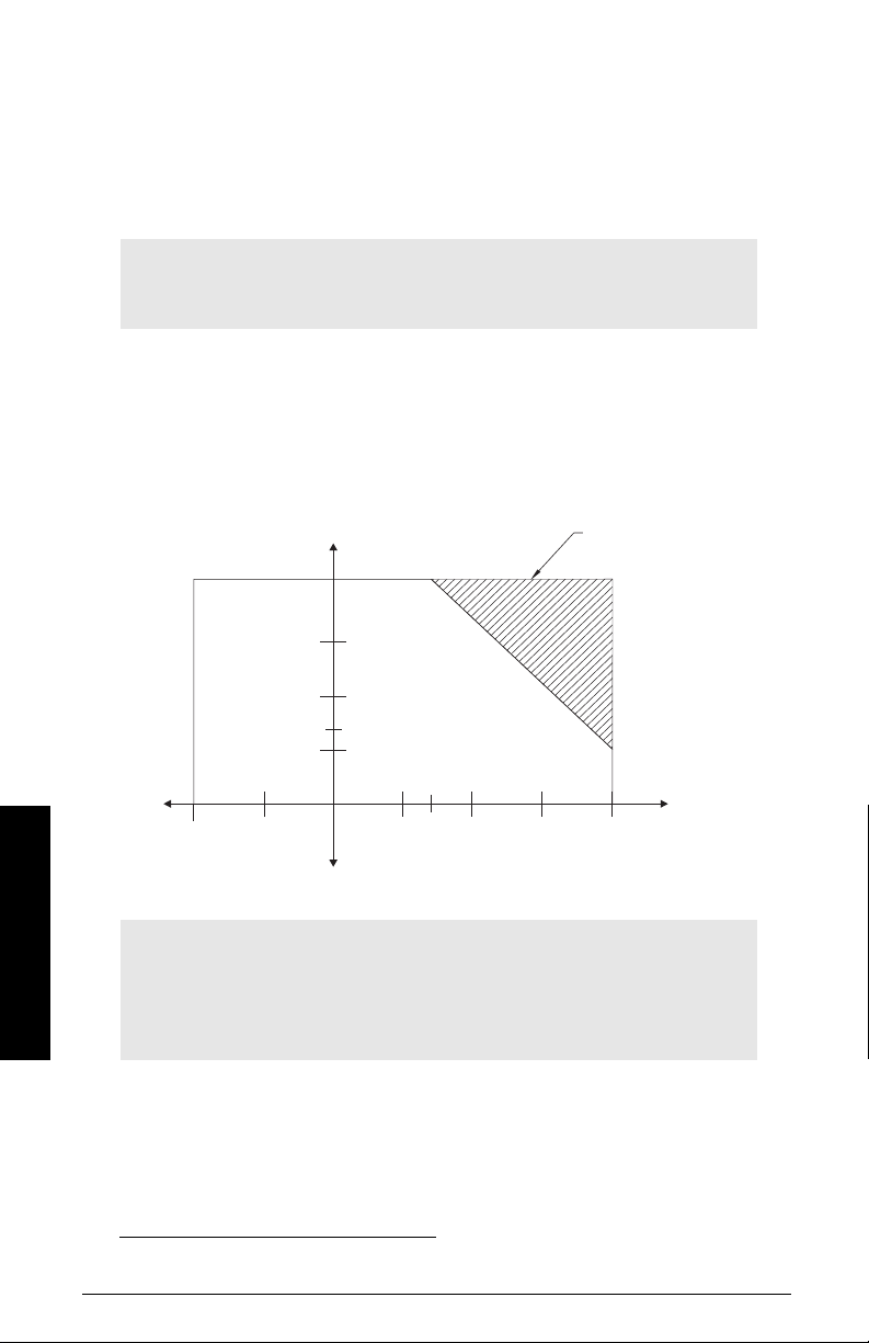
The SITRANS LC 500 provides an analog and a solid-state output. The analog output can
be either a continuous signal proportional to the reading, or in 2-state mode, a mA signal
operating according to NAMUR recommendations for fault signalling
0% (LRV) and 100% (URV) can be set anywhere within the measurement range.
1. The loop current provides either:
a. an analog signal:
• a reading proportional to level (PV) under normal conditions
• an out-of-limits display, ‘ooL’, alternating with PV, in fault conditions (if the
process level exceeds the limit settings [USL] or [LSL])
or:
2
.
1
.
Operation & Application
b. in 2-state mode, provides a mA output:
• 4 mA or 20 mA output for 0% and 100%, under normal conditions
• a 3.6 or 22 mA output in fault conditions (when 2-state fault signalling
[menu 08] is enabled, if the process level exceeds the limit settings [USL or
LSL])
2. The solid-state output can be set to ‘contact open’ or ‘contact closed’, relative to a
covered probe: it can be wired to an external relay and used to activate an external
alarm or a pump via an auxiliary power circuit. It can be activated under normal
conditions by the threshold settings, or Fault signalling can be enabled at menu 18.
1.
Where the stilling well is welded to the tank.
2.
See page 93 for detailed examples.
Page 12 SITRANS LC 50 0 – INSTRUCTION MANUAL 7ML19985GE01
Page 19
solidstate
switch
output
or
2-state
mA output
Indicator - dynamic Primary Variable (units or % of range)
0-100%
current loop connection
Active Shield section
USL
URV = 100%
Upper Threshold Setting = %
(activation hysteresis)
(deactivation hysteresis)
Lower Threshold Setting = %
LRV = 0%
LSL
solidstate
output
auxiliary
power
pump
power
P
3. Upper Threshold Setting and Lower Threshold Setting activate and deactivate the
2-state output, and/or the solid-state output: the settings can be modified to adjust
the hysteresis (the window within which the probe is considered ‘covered’).
4. The speed of response to activation and deactivation of the solid-state and/or
2-state output can be modified by Upper and/or Lower Threshold delays.
5. The PV reading can be stabilized if necessary by applying Damping.
6. Overfill or underfill protection can be set in the absence of those conditions by
applying the Delta Range Setting.
7. Analog Fault Signalling (menu 08) and Digital Fault Signalling (menu 18) take
precedence over the threshold settings (menus 07 and 17).
Level Measurement
The continuous 4-20 or 20-4 mA signal is proportional to the surface level of the product,
with an accuracy of 0.1% of the actual measurement (for example, 1mm/m).
Typically, Lower Range Value (LRV - 0%) is set to 4 mA and Upper Range Value (URV 100%) is set to 20 mA: but the reverse is possible if required. The measurement takes
place anywhere within that range. The LCD displays the value as mA, or pF, or percent,
depending on the setting for the transmitter variable (TV). If you are using HART, you have
the option to define the units.
Operation & Application
7ML19985GE01 SITRANS LC 500 – INSTRUCTION MANUAL Page 13
Page 20

Interface Measurement
The capacitance of the electrode system is dependent on the dielectric constant of the
product surrounding the probe. By comparing the capacitances resulting from different
products with different dielectric constants, it is possible to determine which product is
surrounding the probe.
For miscible products:
Contamination of one product by another can be measured:
100% product A 4 mA
100% product B 20 mA
Values in between 4 and 20 mA represent the ratio of the two products.
For immiscible products:
The interface between two products can be detected by the change in capacitance from
one to the other. (See example,
For Vessels filled with Oil
on page 91.)
Switch action
2-state Switch
The mA output can be used as a 2-state switch set to either 4 or 20 mA. It can be set to go
to 4 mA if the probe is covered and 20 mA if the probe is uncovered, or the reverse.
Solid-state Switch
The solid-state output can be set to ‘contact open’ or ‘contact closed’ with a covered
probe.
Adjustable hysteresis and time delay
Operation & Application
The adjustable hysteresis and time delay settings allow you to adjust the switch action for
applications with a lot of surface movement.
Examples:
With a moving surface that fluctuates between 79% and 80%, if the hysteresis is set
so that 80 is on and 79 is off, the alarm will constantly alternate between on and off.
Either set a time delay, or adjust the hysteresis:
• Set the time delay to 10 seconds (for example): the alarm will be on only after
the surface has been at 80% for at least 10 seconds.
• Reset the hysteresis for 70 (for example): the unit will ignore small surface
fluctuations between 79 and 80%.
Page 14 SITRANS LC 50 0 – INSTRUCTION MANUAL 7ML19985GE01
Page 21

Fault Signalling
The SITRANS LC 500 has three fault signalling options:
• via the loop-current
• via HART
• via the solid-state output or solid-state relay.
Via the loop current
When using the mA signal, the SITRANS LC 500 operates according to NAMUR standards1
for fault signalling. The fault/failure signal can be triggered by a failure in the measuring
system, such as:
• a checksum error
• a loss of signal caused by a defect in the module
• a short circuit in the sensor
• a process failure if the level exceeds the limit settings and if the unit is
programmed to detect this
You can set the Upper and Lower Sensor Limits (menus 0B and 0C) outside the Upper and
Lower Range Value settings. In this case, if the process value is outside its nominal range
(the span between LRV and URV), but still not at a fault/failure level, the continuous mA
output will saturate to 3.8 mA or 20.5 mA. If the process value is outside the Upper or
Lower Sensor Limits, this will be registered as a fault/failure.
Depending on the setting chosen for 2-state Fault Signalling (menu 08), the signal will go to
either 3.6 mA (F: Lo) or to 22 mA (F:Hi). If you do not use communications to receive status
information, we recommend enabling analog fault signalling (menu 08), in order to be
warned if a fault or failure occurs. (This feature is disabled by default.)
Operation & Application
Via HART
See page 75 for
by a response code. It is then up to the Host to decide what to do in the case of a fault
situation. The Host may decide to issue Command 48, which returns more detailed
information.
HART Response Code Information
. Each HART message is accompanied
Via the solid-state output
The solid-state switch can be wired up to an external relay, to provide a second level of
protection. It can then be used to activate a failure alarm, or a level switch. (See page 93
for details of an application using SITRANS LC 500 as a level indicator, with the two-state
output connected to a relay that activates a pump.)
1.
See
NAMUR recommendation NE 43
7ML19985GE01 SITRANS LC 500 – INSTRUCTION MANUAL Page 15
on page 107 for more details.
Page 22

SITRANS LC 500: Probe Configuration
The probe (electrode) comprises a measurement section and an active shield section.
This electrode connects to the capacitance detector portion of the two-wire loop
powered electronic transmitter. The transmitter module is mounted in a powder-coated
aluminum enclosure which provides reliable operation in environments with dust,
moisture, and high-frequency interference.
SITRANS LC 500 Electrode (Probe) Char acteristics
Apply to all general connection configurations:
• The standard SITRANS LC 500 insulated electrode is designed for use in both
conducting and non-conducting liquid applications.
• Most electrodes consist of an active shield portion and a measurement portion,
which combine to form the complete electrode. (This is not the case for cable
electrodes or electrodes with ceramic/enamel insulation.)
• The sum of the active shield length and the measurement length is the total
insertion length.
• The active shield design provides continuous immunity from changes in conditions
at the top of the vessel where levels of vapors, dust, and condensation may be
constantly changing.
• The design of the active shield isolates the starting capacitance of the electrode
from the effects of changes in capacitance due to temperature and pressure
fluctuations that could cause small changes in the seal geometry.
• The carefully-controlled diameter of the electrodes and insulation produces a linear
output over a wide range of capacitance values (1 pF to 3300 pF).
• The end seal is formed as an integral part of the electrode insulation, giving smooth
and uniform characteristics (tested to 55 kV).
• Standard single cone seal
active
shield
Probe Configuration
insertion length
measure-
probe
seal
(inactive)
Page 16 SITRANS LC 500 – INSTRUCTION MANUAL 7ML19985GE01
ment
portion
Page 23

Electrode Assembly
SITRANS LC 500 electrodes come in a variety of formats to provide the necessary
characteristics for correct mounting, chemical compatibility, temperature and pressure
requirements, and dielectric constant of the medium. The main body of the manual
discusses the standard configuration. Other options, with details, are shown in
SITRANS LC 500, alternate versions and application details
Process Connections
The standard threaded process connection (S-Series) with PFA insulated electrode,
including the active shield, provides good results in all measurement situations within the
temperature, pressure, and corrosive capabilities of the materials and seals. This remains
true over a wide range of dielectric constants in both non-conducting and conducting
materials.
Any standard process connection is available with the SITRANS LC 500, and special
versions can be fabricated to match the mounting and application requirements. A wide
range of threaded and flanged fittings is available. (Contact your local Siemens
Milltronics representative for details, or check our website at:
www.siemens-milltronics.com.)
Seal Types
The basic internal seal for the SITRANS LC 500 has a conical-shaped, preloaded
pressure/leak resistant construction. Up to three levels of seal protection are
implemented depending on the integrity requirements of the application. A single or
double cone internal seal forms one or two barriers against leaking, and a third flange
face gasket is also available in the D and DD seal construction. The flange face seal also
provides a design with no metal wetted parts if required.
, page 83.
Appendix E:
Process Connection and Seal Configur ation of SITRANS LC 500
Process Connection Seal Type Seal Description
Threaded S Single Cone
Welded Flange S Single Cone
S Single Cone
D Single Cone + Teflon flange seal
Solid Machined Flange
DD
SD Double Cone (used for stilling well applications)
7ML19985GE01 SITRANS LC 500 – INSTRUCTION MANUAL Page 17
Double Cone + Teflon flange seal. (Consult your
local Siemens Milltronics representative.)
Probe Configuration
Page 24
Pressure and Temperature Considerations
The maximum temperature and pressure of operation for the standard SITRANS LC 500
level probe is 200°C (392°F) and 200 bar (2900 psi). Please consult the pressure curve on
page 18 for qualifications that must be applied to these maximums.
Enamel probes are recommended when the process temperature exceeds 200 °C, and/or
in combination with very high pressure.
Note: Consult your Siemens Milltronics representative if the material to be
measured may be incompatible with the SITRANS LC 500 materials of
construction.
Temperature Versus Pressure Curve for SITRANS LC 500 PFA-insulated
Level Probe
As the temperature approaches 75°C (167°F), the maximum pressure must be derated1.
When the temperature reaches 200°C (392°F), the maximum pressure is limited to 50 bar
(725 psi). This curve is typical for water only. For other, more aggressive chemicals the
derating curve will be more severe.
–1bar (–
14.6 ps i)
pressure
o
0
o
(32
–100
(–148
o
o
C
F)
200 bar (2920 psi)
150 bar (2190 psi)
100 bar (1460 psi)
70 bar (1022 psi)
50 bar (725 psi)
o
–50
C
o
F)
(–58
consult factory when pressure or
temperatures fall within this area
o
70
C
o
F)
(158
o
50
C
F)
(122
100 oC
C
o
o
F)
(212
o
150
C
o
F)
F)
(302
temperature
o
200
C
o
F)
(392
Reference Product: Water
Notes:
• For high temperature and pressure ratings for the Enamel probe, please
contact your Siemens Milltronics representative.
Probe Configuration
• For FM / CSA Explosion Proof applications: if the process temperature
exceeds 135
1.
Decreased within the limits specified in the diagram (maximum 200 bar).
o
C (275 oF), select process seal type SD,DD,HP or HT.
Page 18 SITRANS LC 500 – INSTRUCTION MANUAL 7ML19985GE01
Page 25

Non-standard applications
Applications outside the standard capabilities of the S-Series require a different design
configuration. These non-standard applications include:
Non-Standard Application SITRANS LC 500 Configuration
Non-metallic tanks with both conducting
and non-conducting liquids.
Non-conducting liquids in spherical and
horizontal-cylindrical tanks.
Highly corrosive materials requiring no
metallic wetted parts.
Sanitary/food safe applications. Use SITRANS LC 500 sanitary version.
For more details on alternate configurations, see,
versions and application details on
Use stilling well for second electrode reference.
Use a stilling well as linearizer.
Use flange mount with D, DD seal version.
Appendix E: SITRANS LC 500, alternate
page 83.
Probe Configuration
7ML19985GE01 SITRANS LC 500 – INSTRUCTION MANUAL Page 19
Page 26

SITRANS LC 500: Installation
Notes:
• Installation shall only be performed by qualified personnel and in accordance with
local governing regulations.
• This product is susceptible to electrostatic discharge. Follow proper grounding
procedures.
WARNINGS:
• Disconnect the device before any welding is carried out in the vicinity
of the instrument.
• Provide protection when the solid-state switch is activating an
external relay to prevent possible switch/relay damage resulting from
inductive spikes generated by the relay coil. (See
state switch
on page 21 for details.)
Handling Electrodes
WARNINGS:
• Do not scratch or gouge the PFA electrode insulation since this could
reduce the integrity of the insulation and the useful life of the
electrode.
• Be careful with an enamel-insulated electrode
• Do not damage the insulation jacket on the electrode during shipping,
packing, and installation
proper performance.
• (ATEX 100): Precautions MUST be taken to avoid ignition due to
hazardous electrostatic discharges:
a. Where an isolated probe is used in gas, vapor, or a non-
conductive liquid that is potentially explosive, requiring
apparatus group IIC equipment.
b. Where the probe is used in a potentially explosive dusty
atmosphere.
2
. Any damage to the electrode can prevent
Protection for solid-
1
.
1.
Normally the enamel insulation is protected by a stilling well, which is part of
the design.
2.
Most electrodes use PFA insulation, a very dense and reliable type of Teflon®
that prevents leakage and corrosion of the metal electrode and acts as an
insulator when conductive materials are being measured.
Installation
Page 20 SITRANS LC 500 – INSTRUCTION MANUAL 7ML19985GE01
Page 27
Mounting Instructions
The SITRANS LC 500 is easily installed: simply mount the instrument on the process
connection of the vessel.
Notes:
• The transmitter is specified for use at temperatures ranging from –40 °C to
85 °C (–40
standard option is available with a thermal isolator.
• Before mounting the SITRANS LC 500, check to ensure the threads are
matching to avoid damaging them.
Protection for solid-state switch
• for dc circuits: connect protection diodes in the correct polarity across the relay coil
• for ac circuits: connect a Voltage Dependent Resistor (VDR) or other ac compatible
component (such as zeners and protection diodes in combination) in the correct
polarity across the relay coil
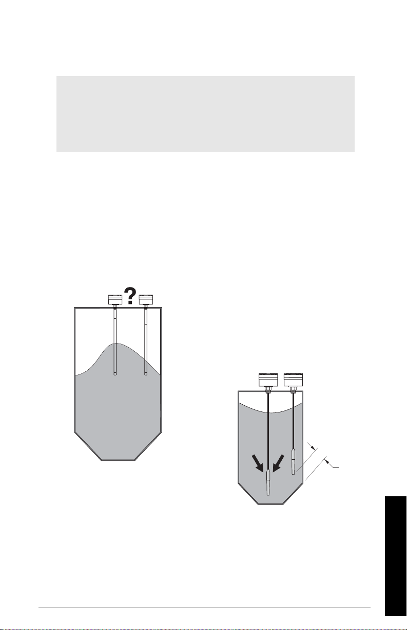
Process Cautions
AUTION: Consider material surface
onfiguration when installing unit.
o
F to 185 oF): if your process temperature is outside this range, a
CAUTIONS:
• With a centrally mounted cable version,
take care that the tensile load does not
exceed probe or vessel rating
• With a cable version mounted close to
the tank wall, take care that the product
does not push the cable against the tank
wall: a spring can be used as a retainer.
??
500 mm
(20”) min.
7ML19985GE01 SITRANS LC 500 – INSTRUCTION MANUAL Page 21
Installation
Page 28

SITRANS LC 500: Standard Level Version
Available with the following features:
• Threaded flanges, welded flanges, and single-piece flanges
• S series, D series, SD series, DD series, and HP series process seals
• Selections of standard ANSI and DIN flanges
• The most common electrode is insulated with PFA. Enamel (HP seal) is also
available (rigid design only).
• Various process connection materials
• Both Rod and Cable versions
Appendix E: SITRANS LC 500, alternate versions and application details
See
onward, for details on dimensions, and for application examples.
, page 83
Installation
Page 22 SITRANS LC 500 – INSTRUCTION MANUAL 7ML19985GE01
Page 29
Interconnection: SITRANS LC 500
Wiring
Supply
Notes:
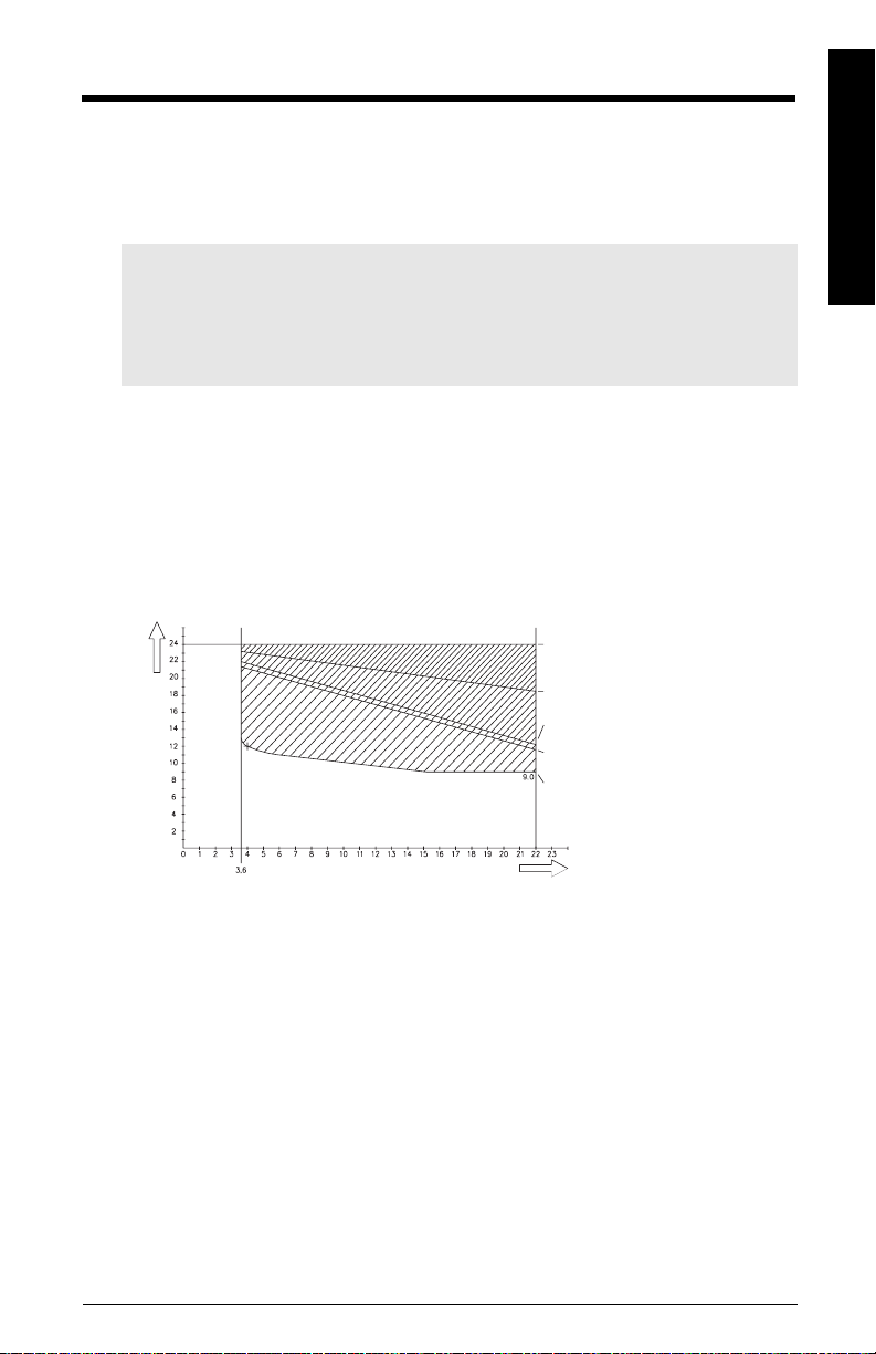
• The transmitter is powered by the current loop and needs at least 9.5-13 Volt on
the terminals: 9.5 V at 22 mA or 12 V at 3.6 mA.
• The maximum supply is 33 Volt. If the voltage is higher the device will shut down.
• The loop-circuit will withstand voltages up to 250 Vac/Vdc without any damage.
The SITRANS LC 500 uses a switched power supply circuit, which makes the most
efficient use of the available power present on the terminals. If the signal current is low,
(4mA), the terminal voltage will be high, and if the signal current is high, (20 mA), the
terminal voltage may be low, due to all the resistive elements in the loop, such as the
barrier and sense resistor.
Voltage drop versus mA for current transmitter operation
voltage drop over 250 ohm
measuring resistance
voltage drop over 280 ohm in
barrier
V-s uppl y
voltage drop over blocking
diode in barrier
margin or voltage drop over
instrument cable
operation voltage,
transmitter
Interconnection
mA
Examples:
• With a 250 Ohm sensing resistor, no barrier and negligible cable resistance, the
overall supply voltage should be at least 15.0 V.
• With a 250 Ohm sensing resistor, a barrier of 280 Ohm, and 20 Ohm cable
resistance (500 m), the total resistance is 550 Ohm, so the overall supply voltage
should be at least 20.5 Volts.
• For a multi-drop application, where the measuring supply is fixed to 4 mA, the
voltage on the terminals of the SITRANS LC 500 should be at least 12 Volts.
The loop circuit is completely isolated from the measurement circuit. It is designed so that
the internal capacitance and inductance on the terminals are isolated and do not factor
in safety calculations.
7ML19985GE01 SITRANS LC 500 – INSTRUCTION MANUAL Page 23
Page 30

Cable
Notes:
• To maintain reliable transfer of the HART modem signals, the RC1 time constant of
the connections should be less than 65 µSec.
• Cable capacitance must also be considered when selecting cable for intrinsically
safe installations.
Interconnection
• For output signals (from the SITRANS LC 500), only the cable and barrier
resistance are relevant. For input signals the measurement resistance is also
relevant.
• Use twisted pair cable, screened as a pair.
1.
RC = Resistance * Capacitance
2.
Or, if you use a common screen over a cable containing multiple twisted pairs,
do not use other pairs for signals that could interfere with HART signals.
Selecting the correct instrumentation cable
• you need to know the cable length, the barrier type (if applicable), and the
measurement resistance
• select a cable that will give you a capacitance time constant of less than 65 µSec
1. Calculate the capacitance for a time constant of 65 µSec, using the following
formula:
tRC×=
R
is the sum of the load resistor and cable resistance.
C
is the sum of the cable capacitance and the capacitances of the connected
device/devices.
2. Determine the cable length allowed, by subtracting the capacitance value of the
device (or devices) on the loop from the total capacitance, and using the maximum
allowable limit of 100 pF per meter (or 1 nF per 10 meters).
Example
1. Calculate the cable capacitance which will give a time constant of 65 µSec:
A twisted pair cable with a conductor cross-section of 1 mm
a copper resistance of 73.6 Ohm/km and a capacitance of 100 pF/m (or 1 nF/10m).
For a standard 28 V 280 Ohm barrier and a 250 Ohm measuring resistance, with a
100 meter cable:
Resistance = 280 (barrier) + 250 (sensing device) + 7.36 (cable)= 537.36
(time constant = Resistance * Capacitance)
tRC×=
2
2
(AWG 18 equivalent) has
CtR⁄=
65 10
C 65 10
Page 24 SITRANS LC 500 – INSTRUCTION MANUAL 7ML19985GE01
6–
× 537.36 C×
s = nF
6–
× 537.36⁄()121==
nF
Page 31

2. Calculate the length of cable allowed, by subtracting the capacitance value that the
device presents on the loop from the total capacitance. SITRANS LC 500 has no
measurable capacitance value, but assume 5 nF. Then use the maximum capacitance
limit (1 m /10 nF) to determine the cable length.
121 5 116=–
116 10 1160=×
nF
m
IS applications: maximum cable length
In an IS application, the IS side of the barrier allows for only 70 nF.
Example:
Subtract the capacitance for the device:
Interconnection
70 5 65=–
65 10× 650=
This allows for a maximum 650 meters on the IS side.
On the other side of the barrier:
121 65 56=–
which allows for 560 meters on that side.
nF
m
nF
Note: The resistance of this length, 650 + 560 meters, could reach 145 Ohm (at
120 Ohm / km), which is too much. In this case, use a thicker cable with lower
resistance.
IIB type/class hazardous area applications: maximum cable length
In IIB type/class hazardous area applications the maximum allowed capacitance value is
330 nF, as long as you are not using HART. If you are using HART, the maximum cable
length will be limited. Depending on cable specifications, the maximum length lies
between 1 and 3 km.
Multi-drop applications: maximum cable length
In a multi-drop application, the total capacitance of all the devices must be calculated.
With five devices, at 5 * 5 nF, the allowable cable length will be considerably limited.
Notes:
• If the device is part of a multi-drop setup, the SITRANS LC 500 sets the current to
4 mA, which inhibits analog signalling, including fault signalling.
• Multi-drop is a HART mode where devices are set to a fixed current, and the
device is interrogated periodically. The maximum number of devices on one loop
is 15, one of which can be an analog mode device.
7ML19985GE01 SITRANS LC 500 – INSTRUCTION MANUAL Page 25
Page 32

Terminals
The SITRANS LC 500 is equipped with two terminal blocks, both insensitive to polarity.
One terminal block is intended for connecting the instrument cable (loop power).
The other terminal block provides the solid-state switch output.
Interconnection
Connecting SITRANS LC 500
The processor integrated circuit is covered by a label which contains product information
and which also acts as a protective seal against moisture.
WARNING: Damage or removal of the protective label voids the
warranty for the SITRANSLC 500.
1. Loosen the retaining set-screw and remove the enclosure cover.
2. Loosen the cable gland and thread the cable through it.
3. Connect the power / signal conductor wires to the current loop terminal block
(any polarity).
4. Ground the enclosure: (see instructions on next page for details).
5. Check to ensure all connections are good.
6. Tighten the cable gland to form a good seal.
7. Replace the enclosure cover and tighten the retaining set-screw.
Note: If you plan to calibrate the unit using push-button adjustment, do so before
replacing the cover.
Connection Diagram
ground lug
protective label
(see warning
above)
solid-state switch
relay (any polarity)
instrument
system ground
measuring signal
(mini-coaxial cable)
ground connection point
for instrument system
Type:
Ser.:
Date:
Rev.:
Tamperingvoids warranty
Page 26 SITRANS LC 500 – INSTRUCTION MANUAL 7ML19985GE01
4-20 mA currentloop connection
(any polarity)
Page 33

Protection for solid-state switch
• For dc circuits: connect protection diodes in the the correct polarity across the relay
coil.
• For ac circuits: connect a Voltage Dependent Resistor (VDR) or other ac compatible
component (such as zeners and protection diodes in combination) in the correct
polarity across the relay coil.
Grounding instructions
Notes:
• Since the measurement occurs between the Measurement and Ground
connections, it is important to have good, low-resistance, reliable connections in
this circuit.
• Use a ground connection wire with a sufficiently large diameter relative to its
length, and not less than 1 mm
• The SITRANS LC 500 measurement circuit is completely isolated from the loop
circuitry: this allows either line of the loop circuit to be grounded if requirements
for Ex safety are followed and if the power supply voltage is less than 33 Vdc.
Connect the housing and the process connection with either the stilling well1 and/or tank
wall, using the ground lug on the housing.
label / protective seal
(DO NOT REMOVE)
2
.
ground lug
Interconnection
instrument system ground
(connected at factory)
Type:
Ser.:
Date:
Rev.:
Tamperingvoids warranty
instrument system
ground connection point
WARNING: When connecting the probe, do not leave moisture or metal scrap
(from the cable shielding, for example) inside the housing. This c ould interfere
with transmitter operation, or cause a short circuit.
1.
Where the stilling well is welded to the tank.
7ML19985GE01 SITRANS LC 500 – INSTRUCTION MANUAL Page 27
Page 34

Grounding Examples: SITRANS LC 500
Grounding is important for two reasons:
1. To prevent interference to the signal: system grounding
2. For safety purposes: safety grounding
Several common applications are illustrated. They are separated into two groups: the first
Interconnection
group illustrates System Grounding and the second illustrates Safety Grounding.
System Grounding (referencing)
For the measuring system to function correctly, the reference electrode must be properly
grounded. Make sure that there is a reliable connection from the instrument housing to
the reference electrode (usually a metal tank). Some common applications involving
system grounding include:
• metal tanks
• metal tanks, cathodically protected
• non-conductive tanks
Metal Tanks
If the metal tank is reliably
grounded, connect the ground lug
on the SITRANS LC 500 to the
earth ground on the tank as
shown.
(See page 26 for connection
diagram.)
ground lug
metal
Page 28 SITRANS LC 500 – INSTRUCTION MANUAL 7ML19985GE01
Page 35

Cathodicall
y
ground lug
Protected Metal
Tanks
Cathodically protected metal tanks
are never directly grounded.
However, the impedance of the
supply source is so low that it will
not cause any problems. The
shielding of the loop cable should
be grounded at one end only (the
tank end) to avoid short-circuiting
the cathode protection voltage.
The ground lug on the
SITRANS LC 500 can be connected
to the tank as shown.
(See page 27 for further grounding
details.)
metal
optional stilling
well
Note: Grounding the SITRANS LC 500 as illustrated above provides only system
grounding for referencing purposes: it does not provide safety grounding.
Non-Conductive Tanks
V
KP
ground lug
Interconnection
Non-metallic tanks always require a
stilling well or proper grounded
conductive medium.
Connect the ground lug on the
SITRANSLC500 to earth ground. If
the stilling well is integral to the
SITRANS LC 500, it is now grounded.
If the vessel has a stilling well
provided, make sure that the metal
parts of the stilling well are properly
grounded.
stilling well
nonmetallic
7ML19985GE01 SITRANS LC 500 – INSTRUCTION MANUAL Page 29
Page 36

Safety Grounding
The safety grounding requirements are determined by the application and the connected
instruments. The SITRANS LC 500 transmitter does not have any special requirements
due to the galvanic separation between the measurement section and the loop section.
Depending on the DCS characteristics, there are three possible grounding options:
• If the DCS measures the current through the loop compared to a common zero Volt
Interconnection
Example 1
point, do not ground the negative side of the current loop because measurement
inputs can be short-circuited.
• If the DCS measures the current in the positive wire or connector, the negative side
of the current loop can be grounded.
• If the DCS has galvanically separated inputs for each measurement channel the
grounding method can be chosen as required.
In hazardous applications a Stahl-type barrier is required, and it is typically mounted on a
DIN rail inside a customer-supplied enclosure located in the non-hazardous area.
If no specific Ex conditions apply, the SITRANS LC 500 can be directly connected to the
DCS. The supply voltage, however, should remain within the limits set by the
SITRANS LC 500. Connecting a SITRANS LC 500 to a DCS does not influence that
equipment. One of the connection cables can be grounded if desired.
Type:
Ser.:
Date:
Rev.:
Tamperingvoidswarranty
3,6 - 22 mA
13 < Vsupp < 32 Vdc.
DCS APPARATUS
GND
COAX
Example 2
In the case of Intrinsically Safe applications, where the DCS equipment measures the
current in the positive connection and the negative connection can be grounded, a
barrier type as shown below is sufficient.
hazardous area
3
Type:
COAX
GND
Ser.:
Date:
Rev.:
Tamperingvoidswarranty
4
Page 30 SITRANS LC 500 – INSTRUCTION MANUAL 7ML19985GE01
non-hazardous area
Stahl barrier: 9002/01-280-
110-00 (or equal)
277
110 mA
1
PA
28V
PA
2
DCS APPARATUS
Rmeas
0V
Page 37

Example 3
If you do not want to ground the negative connection directly, or in the case of
Intrinsically Safe applications where the DCS measures the current in the negative
connection, and that wire cannot be grounded, a barrier type is required as shown below.
hazardous area
Type:
Ser.:
Date:
Rev.:
Tamperingvoidswarranty
Stahl barrier: 90 02/13-280-
3
4
non-hazardous area
110-00 (or equal)
110 mA
277
28V
PA
PA
28V
1
2
DCS APPARATUS
Rmeas
0V
Example 4
In Intrinsically Safe applications where the DCS has galvanically separated inputs, you
can use either the type of barrier shown below, or the type shown in Example 2.
hazardous area
Type:
Ser.:
Date:
Rev.:
Tamperingvoidswarranty
When Ex applications are using an Ex approved Intrinsically Safe (I.S.) power supply unit,
no barrier is required and grounding is optional.
non-hazardous area
Stahl barrier: 9002/01-280-
110-00 (or equal)
280
160 mA
3
160 mA
4
PA
PA
ISS Ground
1
2
DCS APPARATUS
Interconnection
I.S.
Type:
Ser.:
Date:
Rev.:
Tamperingvoidswarranty
DCS APPARATUS
7ML19985GE01 SITRANS LC 500 – INSTRUCTION MANUAL Page 31
Page 38

Communications
The SITRANS LC 500 is equipped with HART communication1protocol2so that settings
and values can be obtained and altered locally
Typical PLC configuration with HART
Interconnection
SITRANS LC 500
Diagnostics
power supply
3
or remotely.
1
R2= 250 Ω
PC/laptop with Simatic PDM or HART communicator
3
The internal diagnostic functions continuously monitor the operation of the transmitter.
An error signal is generated if a failure or irregularity occurs.
The SITRANS LC 500 sends the signal current according to the NAMUR NE 43
recommendation. During normal operation the current remains within the range from 3.8
to 20.5 mA. If the process exceeds its normal limits but is not in a fault or failure situation,
the signal current will be outside the measurement range (4 to 20 mA) but will be limited
to either 3.8 or 20.5 mA.
If a fault or a failure is detected, the signal current is set to either 3.6 mA or 22 mA,
depending on the settings you have chosen. (This feature may be disabled by the user.)
1.
Depending on the system design, the power supply may be separate from the
PLC, or it may be part of the PLC.
2.
A 250 Ohm resistor is required only when the PLC is connected to a HART
modem or a HART communicator.
3.
The HART communicator and a PCL/laptop computer cannot both be connected
to the 4-20 mA loop simultaneously.
Page 32 SITRANS LC 500 – INSTRUCTION MANUAL 7ML19985GE01
Page 39

Current values used as signals from digital transmitters
Current values for signal detection
Measurement value
Fault- mA Value (F)
Interconnection
Fault- mA Value (F)
F = 1
0
3.6
4.0
3.8
F = 0
20
20.5
F = 1
22
Whenever the local situation allows, the zero adjustment and the full scale can be set
using the push-button feature and the appropriate menu selection. In most cases it is
possible to do a one point calibration
1
by using the push-buttons to input the actual level
in %.
The total isolation between the measurement circuit and the current- loop circuit
provides immunity during the use of cathode protected measuring tanks. Connection to
PLC equipment is possible without any difficulty.
• The Upper Range Value (URV) and Lower Range Value (LRV) should be within
the USL to LSL range, but can be set anywhere within that range.
• An interruption of the measuring connection will be detected: a loose or
interrupted connection results in up to 0.5 pF capacitance, which is below the
adjusted LSL and thus signals a FAULT condition.
Applications for Solid-state Output
The solid-state output is a polarity independent switch output. The solid-state switch has
two possible functions.
• it can be activated/deactivated when the product level reaches the upper/
lower threshold settings (set in menus 15 and 16)
• or it can be activated if a fault or failure is detected
2
(set in menu 18)
mA
See page 93 for an illustration of a typical application using SITRANS LC 500 as a level
indicator, with the solid-state output connected to a relay which activates a pump.
The solid-state switch has its own parameter set: menu items 13 to18, (see
00 to 0F and 10 to 1F
on page 37, and
Rotary Switch Positions – Quick Reference
Menu Levels
chart on
page 41).
In menu 0E and menu 0F, you set the Upper and Lower Range Values (URV and LRV) for
relay operation. Within that range, the solid-state switch has independent settings for
1.
See
Calibration using push-button adjustment
2.
See
Fault Signalling
on page 15 for details of fault conditions.
on page 43.
7ML19985GE01 SITRANS LC 500 – INSTRUCTION MANUAL Page 33
Page 40

Upper and Lower Threshold, (menus 13 and 14) and the accompanied delays (menus 15
and 16).
Initially the solid-state output is disabled for both signal output and fault/failure output
(menu 17). When the solid-state switch is to be operated as fault/failure output (for
example, for a separate shutdown system), we recommend disabling the operation for
signal output (select Disabled Mode in menu 17 on page 70). There is no delay in the
operation for fault/failure output.
Interconnection
Notes:
• The solid-state output should only be used in circuits where the current is limited
by a proper load.
• Due to the limited switching capabilities of the solid-state switch component, an
auxiliary relay must be applied when switching high-current/high-voltage
apparatus.
Switch Protection (Diode)
WARNING: When the solid-state switch is activating an external
relay, protection diodes must be connected in the correct polarity
across the relay coil to prevent possible switch/relay damage
resulting from inductive spikes generated by the relay coil.
Factory Settings
The SITRANS LC 500 has a number of default factory settings. If the required settings for
the application are known, the settings can be modified during final testing.
Note: To restore factory settings, use menu item 12 (see
for details).
Factory Settings
on page 72
Settings:
Setting Description
ID Has a unique serial number
TV0 Units PF
TV0 UL 3300 pF [switch position (0)C]
TV0 LL 1.666 pF [switch position (0)B]
TV0 URV 3300 pF [switch Position (0)F]
TV0 LRV 0.00 pF [switch Position (0)E]
AO1 4-20 mA is 0-100% [position (0)8]
TAG "customer input data via HART"
DESCRIPTOR "customer input data via HART"
MESSAGE "Siemens Milltronics P I"
Page 34 SITRANS LC 500 – INSTRUCTION MANUAL 7ML19985GE01
Page 41

Setting Description
DATE "customer input data via HART"
SENSOR SERIAL NUMBER "customer input data via HART"
FINAL ASSEMBLY NUMBER "customer input data via HART"
TV1 Units UNDEFINED
TV1 LRV 0 [switch position (0)E, TV1]
TV! URV 1.0 [switch position (0)F, TV1]
• The Upper Sensor Limit (USL) and Lower Sensor Limit (LSL) are set to 3300 and
1.666 pF respectively, and the following conditions apply: the Upper Range Value
(URV) and Lower Range Value (LRV) should be within the USL to LSL range, but
can be set anywhere within that range.
• An interruption of the measuring connection will be detected: a loose or
interrupted connection results in up to 0.5 pF capacitance, which is below the
adjusted LSL and thus signals a FAULT condition.
Interconnection
7ML19985GE01 SITRANS LC 500 – INSTRUCTION MANUAL Page 35
Page 42

The SITRANS LC 500 User Interface
The SITRANS LC 500 user interface consists of the display (LCD), the rotary switch, and
two push-buttons. The rotary switch enables you to select a particular item and/or
variable for read-out and/or adjustment: the push-buttons allow you to select and/or alter
a read-out or a value.
User Interface
rotary switch
menu selector
RED (+) push-button
increment value
BLUE (–) push-button
decrement value
Type:
Ser.:
Date:
Rev.:
Tamperingvoids warranty
LCD
label
(protective
seal)
solid-state
switch relay
(any polarity)
current-loop
connection
(any polarity)
coaxial connector
probe connection
measurement connection
earth TAB
tank / vessel frame
The LCD (display)
The seven-segment LCD (display) shows the value and/or diagnostic information. It is
mainly for numeric data, but there are also a number of indicators which use alphabetic
characters. A list of these LCD displays, together with the associated menu items, is
shown in
Appendix B: LCD display examples
left-most colon:
indicates value
accepted
(debounce time
passed)
left-most decimal point/heartbeat indicator (flashes twice
per second)
left-arrow indicates Menu Level 10 to 1F
The LCD will hold information for a long time even when not refreshed (for example, if
there is a loss of power). The heartbeat indicator blinks continuously whenever the
device is working. A still heartbeat signals that the device has stopped working.
on page 74.
value MINUS sign (– )
Page 36 SITRANS LC 500 – INSTRUCTION MANUAL 7ML19985GE01
Page 43

How to access the data:
Access data in the transmitter from 28 menu items divided between two menu levels: 00 to
0F and 10 to 1F. Use the rotary switch and push-buttons in combination to select an item
and adjust the value.
The functions of each menu item are illustrated in application examples on page 93 to 94.
Details on using each menu item are given in
Rotary Switch Positions – Quick Reference
also
Appendix A: Menu Groups
on page 41 showing the switch position
and button press combinations used to carry out different functions.)
Menu Levels 00 to 0F and 10 to 1F
on page 54. (See
Menu 00 to 0F Description Menu Group Details
09 Stepsize Update Value
0A Damping page 56
0B Lower Sensor Limit page 56
0C Upper Sensor Limit page 57
0D Delta Range Setting page 57
0E Lower Range Value page 58
0F Upper Range Value page 59
00 Dynamic Value (PV)
02 Max./Min. Recorded Value page 60
01 Transmitter Variable select for PV page 60
03 Upper Threshold Delay: 2-state mode
04 Lower Threshold Delay: 2-state mode page 62
05 Upper Threshold Setting: 2-state mode page 63
06 Lower Threshold Setting: 2-state mode page64
07 Analog Signalling Mode page 64
08 Analog Fault Signalling page 66
Tra nsmi tter
Variable Settings
Tra nsmi tter
Variable Value
Analog Output
Signalling
(loop-current)
page 55
page 59
page 62
Menu 10 to 1F Description Menu Group Details
10 Dynamic Value (PV)
1C Transmitter Variables Dynamic Value page 61
13 Upper Threshold Delay: solid-state output
14 Lower Threshold Delay: solid-state output page 68
15 Upper Threshold Setting: solid-state output page 68
16 Lower Threshold Setting: solid-state output page 69
17 Digital Signalling Mode page 70
18 Digital Fault Signalling page 71
11 Output Signal Processing Test
12 Factory Settings page 72
19 Range Inversion page 73
1F Keylock Level page 73
1A
1B
1D
1E
Non-operational Spare
Tra nsmi tter
Variable Values
Digital Output
Signalling
Miscellaneous
page 59
page 67
page 72
User Interface
7ML19985GE01 SITRANS LC 500 – INSTRUCTION MANUAL Page 37
Page 44

The rotary switch
The rotary switch gives you access first to the menu level and then to the menu item.
The rotary switch has a small slot where the current position can
be read. The positions are read clockwise, and in increasing order:
C
D
B
A
8
9
7
6
3
4
5
The push-buttons
0, 1, 2, 3, 4, 5, 6, 7, 8, 9, A, B, C, D, E, and F. The position wraps from F
E
to 0.
F
0
The switch can be turned in either direction. When it is turned to a
1
new position, the LCD displays the new menu selection for 1
2
second, followed by the data for that position.
Certain menu selections return more than one piece of information
per item: in that case the display alternates between the two
values, for example, PV Value / Fault status.
User Interface
The push-buttons allow you to change the value of a menu item. Use the RED (+) button to
adjust a value up; the BLUE (–) button to adjust a value down; or press both
simultaneously for special applications. For a table showing the combinations of rotary
switch positions and button presses used to carry out different functions, see page 41.
Access to a menu item:
Notes:
• For a detailed description of each menu item, see Appendix A, page 54: the
functions of each menu item are illustrated in application examples on page 93
to 94.
• Change over from Menu LEVEL 0 to Menu LEVEL 1 is only possible at position 0,
from menu item 00 to 10 or vice-versa. (See page 42 for detailed instructions.)
1. First select Menu LEVEL 0 or Menu LEVEL 1.
2. Turn the rotary switch to the number of the desired item.
Adjusting the value
Notes:
• The push buttons are preset with a delay called the debounce time.
• Keeping one or both buttons pressed continuously will trigger an auto-repeat in
some menus.
1. Select a menu item.
2. Press the RED (+) or BLUE (–) push button to adjust the value up or down:
acceptance is indicated when the left-most colon on the LCD appears. (You have to
press longer than the debounce time to have the action accepted: the debounce
time varies according to the menu item selected.)
Page 38 SITRANS LC 500 – INSTRUCTION MANUAL 7ML19985GE01
Page 45

Transmitter Variables
• Transmitter Variable 0 (TV0) is the capacitance as measured by the device.
• Transmitter Variable 1 (TV1) is a computed variable: the dynamic value is a
computed derivative from the range settings for TV0.
Transmitte r Variable User-defined Functions Units
TV0
TV1 Can be user-defined
URV, LRV, Damping, USL and LSL
pF
User Interface
7ML19985GE01 SITRANS LC 500 – INSTRUCTION MANUAL Page 39
Page 46

Start-up: SITRANS LC 500
Capacitance measurement systems require the instrument to be calibrated for a
particular application. Two methods of calibration are available:
• push-button (for instructions, see page 43).
• HART (for instructions, see page 46).
Quick Start
We strongly recommend you read the full manual to use your device to its fullest
potential. However, if it is possible to adjust the level of the tank to the 0% and 100%
levels, you can use the quick start sequence below to calibrate the instrument and get
started.
Notes:
• Change over from Menu LEVEL 0 to Menu LEVEL 1 is only possible at position 0,
from menu item 00 to 10 or vice-versa. (See page 42 for detailed instructions.)
• For a table showing all the combinations of rotary switch positions and button
presses used to carry out different functions, see page 41.
• For a detailed description of each menu item, see Appendix A, page 54.
Quick Start Sequence
1 Calibrate the 0% setting (LRV - lower range value): menu 0E
Start Up
2 Calibrate the 100% setting (URV - upper range value): menu 0F
3 View primary variable (PV): menu 00
4 The SITRANS LC 500 is now ready to operate.
For instruments without a stilling well, the 0% setting needs to be calibrated after the
device is installed, and with the tank/vessel empty. Calibration is also sometimes necessary after installing a SITRANS LC 500 fitted with a stilling well, although in most cases
the 0% setting is calibrated at the factory.
Set value for 0% (LRV): units must be pF (Menu 01 must read Pv = 0).
a Bring the product level to the height that corresponds to 0%.
b Turn the rotary switch to E (Empty).
c Press both buttons and hold for about 1 second: the 0% point is now set.
Set value for 0% (LRV): units must be pF (Menu 01 must read Pv = 0).
a Raise the product level to the height that corresponds to 100%.
b Turn the rotary switch to F (Full).
c Press both buttons and hold for about 1 second: the 100% point is now set.
Turn the rotary switch to 0. The LCD displays the actual pF reading.
Page 40 SITRANS LC 500 – INSTRUCTION MANUAL 7ML19985GE01
Page 47

PV
URV Value
PV
Increase
for 20 mA
PV
URV
URV
URV =
Decrease
Actual
Val ue (P V)
Level
Keylock
Level
Keylock
Increase
Level
Keylock
Decrease
—
Spare
—
Spare
Var 0
Transmitter
—
Spare
—
Spare
MODE
Normal /
Fault signal
(Solid-state
Status
Solid-st ate
Var 1
Read-Out
Inverse
Output)
Output
Read-Out
Transmitter
Transmitter
MODE
MODE
Inverse
Normal /
Set FAULT =
Set FAULT =
Solid-state ON
Set Covered =
Set Covered =
Solid-st ate ON
Var 2
Normal /
Var 3
Read-Out
Read-Out
Transmitter
Mode
Tog g le
Inverse
Operating
Disable Fault
for Solid-state
Solid-st ate OFF
for Solid-state
Disable Switch
Solid-state OFF
Menu LEVEL 1 (10 to 1F)
Switch
old Point
Lower Thresh-
Lower Thresh-
Increase
tion Transistor
old De-Activa-
old Point
Decrease
Threshol d
Point to 25%
Preset Lower
Lower Thresh-
PV Units PV Units PV Units PV Units PV Units
Numeri-
Numeri-
cal
cal
PV
LRV Value
PV
Delta Val ue
PV
UPPER limit
PV
LOWER limit
Val ue
Dampin g
Step
Actual
Fault signal
Loop Current
for 4 mA
for 4 c.q.
Size
22 or 3.6 mA
in mA
20 mA
PV
Increase
PV
Increase
PV
Increase
PV
Increase
Increase
Dampin g
Increase
Step Size
Set FAULT:
Set Covered:
LRV
Delta
UPPER limit
LOWER limit
Val ue
to 10000
20 mA (Hi)
PV
LRV
Decreas e
PV
Decrease
PV
Decreas e
PV
Decreas e
Dampin g
Decreas e
Step Size
Decrease
22 mA
Set FAULT:
Set Covered:
Value (PV)
LRV = Actual
Delta
= Min.
URV– LRV
Limit to
3.6 mA
Preset Upper
Set to 1 Set to 1 Preset
Fault signal
Set Analog
Actual (PV)
Actual (PV)
Lower Limit to
Disable
Range
4 to 20 mA (Anl)
UPPER limit
LOWER limit
Val ue
to 0.01
4 mA (Lo)
Menu LEVEL 0 (00 to OF)
old
De-Activation
Current signal
Lower Thresh-
Poi nt
Lower
Increase
Threshol d
old Point
Decrease
Lower Thresh-
Preset Lower
Threshol d
Point to 25%
01 2 3 4 5 6 7 8 9AB C D E F
Rotary Switch Positions – Quick Reference
old
Upper Thresh-
Time Dela y
De-Activation
Activation
Time Dela y
Lowest
Highest/
PV Units Seconds Seconds % % mA mA
Show
select PV
Selection
or
PV Value
PV Units Num.
Units
NO KEYS
Upper
Increase
Activati on
Current signal
Current sig-
PV
variable
Value
Threshol d
Current signal
Increase
Delay Time
nal
Increase
Delay Time
Highest
Memory
Read-out
PV Memory
TVmax
Step TV0 to
Set
Fault
Level
Menu
read-out
Up Key-
RED (+)
old
Poin t
00 to 0F
Poin t
Decreas e
Upper Thresh-
Decreas e
Decrease
Lowest
PV Memory
to TV0
Step TVmax
Set
Menu
Down
Threshol d
Point to 75%
Preset Upper
Tog g le
Delay Time
Delay Time
00 < – > 10 0
Tog g le
Delay Time
Delay Time
00 < – > 10 0
Read-out
Level
Key-
BLUE (–)
actual PV
Reset Hi/Lo
memories to
Se t
% Mode
Level
Menu
Show-
10 to 1F
Both
Keys
Default * TVO * 00 00 75% 25% Analog Disabled 1.0 1 1.666 pF 3300 pF 3300 pF 0 pF 3300 pF
Seconds Seconds % % O/ C O/C nor / inv Resp. Units Keylock
Factory
Settings
Numerical
PV Units
Units
Switch
old Point
RED (+)
old Point
Decreas e
Decreas e
Delay Time
Decrease
Delay Time
FAC
tings)
00 to 0F
Set Men u
Down
Threshol d
Point to 75%
Preset Upper
Upper Thresh-
Time
Delay Time
00 < - > 10 0
Toggle Delay
Time
Delay Time
00 < - > 10 0
do it Toggle Delay
tings)
(factory set-
tus
Invert Sig-
nalling Sta-
Level
Key-
Level
Show
Menu
10 to 1F
BLUE (–)
Both
Keys
Default * * * 00 00 75% 25% Disabled Disabled nor * * * * * 0
Upper Thresh-
Time Delay
De-Activation
Activation
Time Delay
FAC
(factory set-
check
Display
or
PV Value
NO KEYS
Upper Thresh-
Switch)
Increase
Transistor
Switch
Increase
Transistor
FAC
tings)
(factory set-
Fault code
Level
Fault
Set Men u
Value
read-out
Up Key-
Increase
Transistor
old Activation
Page 48

Menu levels 0 and 1
Menu level 00 to 0F is the default start-up setting after power is applied or after a reset.
Menu Level 10 through 1F is flagged in the LCD by an left-arrow indicator in the upper left
corner of the LCD.
To change from menu 00 to menu 10:
1. Set the rotary switch to 0.
2. Press and hold the BLUE (–) button.
3. While the button is pressed, the display shows : M 10 followed by : SEL 1,
indicating that the current menu level is now 10 to 1F: a left-arrow is displayed in
the top left corner of the LCD.
4. When the button is released, the LCD displays PV (primary variable): the leftarrow remains visible.
To change from menu 10 to menu 00 :
1. Make sure the rotary switch is set to 0.
2. Press and hold the RED (+) button.
3. While the button is pressed, the display shows: M 00 followed by : SEL 0,
indicating that the current menu level is 00 to 0F: no left-arrow is displayed in the
top left corner of the LCD.
4. When the button is released, the LCD displays PV.
In menu 00 or 10, to see the current menu level selection, briefly press one of the buttons
(less than a second): the current selection is momentarily displayed.
Notes:
Start Up
• Check the menu level when using the rotary switch to select a menu item: the leftarrow in the top left corner of the LCD indicates menu level 1.
• The rotary switch must be set to 0, in order to change from one menu to the other.
• Hold the RED (+) or BLUE(–) buttons for longer than the preset delay, or debounce
time, when altering a value: the debounce time is generally about a second, but
varies from one menu item to another.
• Keylock level (menu 1F) must be set to 0 (no restrictions) to enable you to change
settings.
Start up using push-button calibration: (overview)
• Check that Keylock level is set to enable calibration
• If required, change the transmitter variable: select units as pF, units user-defined, or
values as percent
• Calibrate value for 0%
• Calibrate value for 100%
• Set display for dynamic PV (primary variable): select values displayed as percent or
units
• SITRANS LC 500 is ready to operate
Page 42 SITRANS LC 500 – INSTRUCTION MANUAL 7ML19985GE01
Page 49

Calibration using push-button adjustment
Notes:
• To toggle between menu level 0 and menu level 1, set rotary switch to 0, and use
RED (+) or BLUE (–) push-button to select menu.
• To reset values to factory settings, select menu 12. Press and hold both buttons:
the LCD displays do it, followed by FAC A when the buttons are released.
• For a complete list of menu items, see
Appendix A: Menu Groups
Reset keylock level if necessary to enable settings to be changed: menu 1F
(no change is necessary if the factory setting has not been changed)
1. Select menu 10, then set the rotary switch to F.
2. Use the BLUE (–) push-button to decrease the value to 0: display reads PL 0 (no
restrictions).
Reset selection for transmitter variable if necessary to TV0 (units are pF):
menu 01
(no change is necessary if the factory setting has not been changed)
1. Select menu 00, then turn the rotary switch to 1.
2. Use the BLUE (–) button to adjust the value to 0: the display reads Pv = 0.
Calibrate the 0% setting (LRV - lower range value): menu 0E
For instruments without a stilling well, the 0% setting needs to be calibrated after the
device is installed, and with the tank/vessel empty. Calibration is also sometimes
necessary after installing a SITRANS LC 500 fitted with a stilling well, although in most
cases the 0% setting is calibrated at the factory.
1. Set value for 0% (LRV): units must be pF (Menu 01 must read Pv = 0)
a. Bring the product level to the height that corresponds to 0%.
b. Set the rotary switch to E (Empty).
c. Press both buttons and hold for about 1 second: the 0% point is now set.
, page 54.
Start Up
Calibrate the 100% setting (URV - upper range value): menu 0F
• method 1: if it is possible to bring the actual product level to 100%
• method 2: if the current product level is known, you can calculate the
percentage value, and calibrate for full scale in %. The closer the actual level is
to 100%, the more accurate this result will be.
Method 1. Set value for 100% (URV): units must be pF, (at Menu 01, Pv = 0)
a. Raise the product level to the height that corresponds to 100%
b. Set the rotary switch to F (Full).
c. Press both buttons and hold for about 1 second: the 100% point is now set.
7ML19985GE01 SITRANS LC 500 – INSTRUCTION MANUAL Page 43
Page 50

Start Up
Method 2. Set value for 100% (URV): values must be displayed as percent (at menu 01,
Pv = P)
a. Calculate the percentage value of the current level.
b. Set rotary switch to 1, and press both buttons to adjust the value to P.
c. Set the rotary switch to F (Full).
d. Press the RED (+) or BLUE (–) button to increase or decrease the reading on the
LCD until it matches the known (actual) percentage. The push-buttons appear to
work in reverse for this function
1
. You may need to decrease the stepsize value
(menu 09) in order to reach the desired value.
e. 100% value is set.
Example:
Set LRV in capacitance mode, then set menu 01 to Pv = P (percent mode) and immerse
the probe in the product (values shown below are arbitrary example values only):
0% ( LRV) =14.20 pF
100% (URV) = 34.20 pF
Span = 20 pF
Current level = 28.20 pF
Change in capacitance = 28.20 – 14.20 = 14
Current percent of span = 14/20 = 70%
LCD displays 78.00 (percent)
In this example, to decrease the reading to 70.00, you need to press (+) to increase the
span, which will reduce the percentage, until the value reaches 70.00. If the steps are too
big you need to change the stepsize (menu 09) to a lower value.
Changing stepsize value: menu 09
The factory setting is 1: the LCD displays U: 1.0
Set rotary switch to 09, and press BLUE (–) button to reduce stepsize: values range from
0.01 to 1,000.
Example:
LCD displays 78.00 (percent)
Known percent of span = 70%
Decrease needed is 8, but setting for stepsize is 10: menu 09 set to U: 10.
Press BLUE (–) button to reduce stepsize to 1: LCD displays U: 1.0.
Return to OF, and decrease value to 70.00 (percent).
You may still need to reduce the stepsize further. If changing the stepsize value has no
apparent effect, press both buttons simultaneously to change the reading to 100%. From
there you may adjust it until the correct percentage reading is reached.
1.
In capacitance mode, the display for menu 0F shows the actual URV, but in percent mode, when you adjust the reading, you are in fact stepping the capacitance value. As you step the capacitance down, you decrease the range and
reduce the span, so the percentage increases in relation to the smaller span.
Therefore the (+) and (–) buttons appear to function in reverse.
Page 44 SITRANS LC 500 – INSTRUCTION MANUAL 7ML19985GE01
Page 51

Select capacitance or percent mode for dynamic primary variable (PV):
menu 01
a. To see the value displayed as percent, select menu 01 and press both buttons to
set Pv = P.
b. To see the value displayed as pF, select menu 01 and increase or decrease the
value till Pv = 0.
The SITRANS LC 500 is now ready to operate. For a table showing the different functions
available, and the combinations of switch position and button presses used to carry out
these functions, see page 41. For a detailed list of menu items, see
on page 54.
Groups
Appendix A: Menu
Notes:
• During normal operation, the 4 and/or 20 mA point can be calibrated at any time.
• If the difference in the capacitance value between the 4 mA point and the 20 mA
point is smaller than the minimum span value (3.3 pF), the new value will not be
accepted.
• To revert to factory settings, select menu 12 and press both buttons: the display
will read FAC A.
Start Up
7ML19985GE01 SITRANS LC 500 – INSTRUCTION MANUAL Page 45
Page 52

Calibration using HART
Start Up
The SITRANS LC 500 transmitter can be calibrated using HART, with a HART
communicator
circumstances determine the manner in which calibration takes place. If the
circumstances allow the product to be brought to the 0% and 100% point level, calibration
is simple.
1
; a laptop running Simatic PDM, or with the Host system (DCS). The local
Notes:
• Use the arrow keys, up, down, forward and back, to navigate within the menus.
• Use the back arrow to return to previous screens.
Examples of calibration using a Rosemount 275 hand-held communicator, fitted with the
GENERIC device descriptor:
Example 1
For situations where the level of the product can be easily adjusted to 0 and 100%.
1. Switch on the 275 and request connection with the SITRANS LC 500.
a. Select: Online
b. Select: Device setup
c. Select: Diag service
d. Select: Calibration
e. Select: Apply values
(Display reads: Loop should be removed from automatic control. Select: Ok)
f. Select: 4 mA
g. Select: Apply new 4 mA input
2. Bring the level of the product to the level which corresponds with 4 mA.
a. Select: Read new value
b. Select: Set as 4 mA value: the 4 mA point has now been set.
c. Select: 20 mA
d. Select: Apply new 20 mA input
3. Bring the level of the product to the level which corresponds with 20 mA.
a. Select: Read new value
b. Select: Set as 20 mA value: the 20 mA point has now been set.
c. Select: Exit
(Display reads: Loop may be returned to automatic control. Select: Ok)
Calibration is complete.
1.
For a diagram showing how to connect the HART communicator, see
configuration with HART
Page 46 SITRANS LC 500 – INSTRUCTION MANUAL 7ML19985GE01
on page 32.
Typica l PLC
Page 53

Example 2
For situations where the capacitance values are known in advance.
1. Switch on the 275 and establish connection with the SITRANS LC 500.
a. Select: Online
b. Select: Device setup
c. Select: Diag service
d. Select: Calibration
e. Select: Enter values
f. Select: PV LRV
2. Enter required capacitance value for 0% of the range.
a. Select: PV URV
3. Enter required capacitance value for 100% of the range.
a. Select: Send (the values are now sent)
b. Select: Put loop in manual
c. Select: Return loop to auto
Example 3
For situations where the capacitance values are unknown, and the level of the product
cannot be easily adjusted to 0% and 100%. In this case it is necessary to measure the
capacitance value at various levels. These values can be read in % with the 275
communicator.
Note: The more accurately the values are measured at 0% and100%, the more
accurate the final result will be.
Start Up
1. Switch on the 275 and establish connection with the SITRANS LC 500.
a. Select: Online
b. Select: PV
c. The measured value can be read continuously, even if the current loop value is
min. or max.
2. Write down the measured value in pF, and record the corresponding level.
Example:
• the measured PV value is 181 pF at 79%
• the measured PV value is 52 pF at 17%
(181– 52)pF
(79 – 17)%
7ML19985GE01 SITRANS LC 500 – INSTRUCTION MANUAL Page 47
= 2.08 pF per %.
Page 54

Start Up
The capacitance value for a 17% change in level is 17 * 2.08 = 35.37 pF.
The capacitance value for 0% is 52 – 35.37 = 16.62 pF (initial capacitance value).
The capacitance value for 100% is (100 * 2.08) + 16.62 = 208 + 16.62 = 224.6 pF.
3. Enter the calculated values for 0% and 100%, to calibrate the SITRANS LC 500 as
described in Example 2.
Example 4
For situations involving the re-adjustment of the LRV where the actual value is
determined to be one value but the measurement shows a different value.
1. Switch on the 275 and establish connection with the SITRANS LC 500.
a. Select: Online
b. Select: PV
The measured value can now be read continuously.
2. Write down the measured value in pF: assume it is 80 pF.
Example:
Assume that the URV is set to 240 pF, that the actual value is 17%, but the
measurement is showing a different value.
the measured value = 80 pF
(100 – 17) % = 83%
(240 – 80) pF = 60 pF
160 pF
83%
The capacitance value for 100% (URV) is 100 * 1.927 = 192.7pF
= 1.927 pF per %
The new LRV should be 240 –192.7 = 47.22 pF.
3. Adjust URV and LRV by following the steps in Example 2.
If the DCS and/or the 275 are fitted with the Device Descriptor for the SITRANS LC 500,
more functions can be used.
The available functions are:
Number Description
(48) Read Additional Transmitter Status
(38) Reset Configuration Changed Flag
(128) Set Alarm Select
(129) Adjust for Product Build-up on Sensor
Page 48 SITRANS LC 500 – INSTRUCTION MANUAL 7ML19985GE01
Page 55

Number Description
(130) Read Failsafe Mode selection
(131) Return device configuration info
(132) Set Variable Upper Limit
(133) Set Variable Lower Limit
(134) Write keylock value
(135) Read keylock value
(138) Write simulation time and value
(139) Read simulation time and value
(140) Write TV1 Units, URV and LRV
(141) Read TV1 Units, URV and LRV
(144) Reset Max/Min recorded PV
(145) Read Max/Min recorded PV
(150) Write analog signalling mode
(151) Read analog signalling mode
(152) Write digital signalling mode
(153) Read digital signalling mode
(154) Write analog threshold settings
(155) Read analog threshold settings
(156) Write digital threshold settings
(157) Read digital threshold settings
(160) Write timers analog signalling
(161) Read timers analog signalling
(162) Write timers digital signalling
(163) Read timers digital signalling
Start Up
7ML19985GE01 SITRANS LC 500 – INSTRUCTION MANUAL Page 49
Page 56

Maintenance
Test function
Auto Self-testing
SITRANS LC 500 continuously performs a variety of tests to verify that the device is
functioning correctly. These include a test where a known capacitor is applied to the
input of the device. The internal results must match the known capacitance value. If a
deviation is detected the Fault/Failure can be flagged with a pre-set loop-current (user
configurable) and as a status in each HART message.
Manual testing
In order to test the proper processing of signals in PLC/DCS equipment, SITRANS LC 500
allows you to invert the output signal status. In Menu 11, when both buttons are pressed
simultaneously, the signal outputs switch to their opposite state. When the buttons are
released, the outputs revert to the initial state.
Note: If a Fault or Failure is present, its signal will take precedence over the test
function.
If no Fault/Failure is present and no buttons are pressed, the display for menu 11
alternates between two test patterns which together illuminate all the segments of the
display. If the loop-current control is in analog mode the loop current will hold the last
value, during this test.
Inspections
Under normal circumstances, the SITRANS LC 500 transmitter requires no maintenance.
However, we recommend that you schedule periodic inspections of SITRANS LC 500.
The inspection can be subdivided into two parts:
1. Visual Inspection: confirm the following conditions:
a. Inside enclosure is clean and dry.
b. Enclosure sealing is intact and functioning properly (not hardened).
Maintenance
Page 50 SITRANS LC 500 – INSTRUCTION MANUAL 7ML19985GE01
c. All screw connections are tight.
d. Ground connections inside the housing are solid.
e. Ground connections outside the housing are solid.
Page 57

f. The coaxial connector is free of dirt or deposits.
g. No cables or wires are jammed under the cover.
2. Functional Checks
a. Check for required minimum terminal voltage (see page 23 for supply voltage
requirements).
b. Confirm that Menu 08 is set to enable analog fault signalling: display should read
F: Hi or F: Lo. (If there is a fault condition, it will read F= Hi or F= Lo, when buttons
are released.)
c. Check that the current goes to the alarm position (3.6 or 22 mA) if the coaxial
plug is unplugged: at menu 00, the LCD should display ‘ooL’. After the test,
replace the coaxial plug.
d. Confirm that Menu 18 is set to enable digital fault signalling: the LCD should
display F= cc or F= co, when buttons are released.
e. Check that the solid-state output goes to the alarm position (open/close) if the
coaxial plug is unplugged. After the test, replace the plug.
f. Via HART:
Check that the PV goes to 0 pF when the coaxial plug is unplugged, (±0.15 pF is
allowed). If it does, switch the output current to 4 mA and check the current
through the loop, then to 20 mA and check the current through the loop. After the
test, replace the plug.
7ML19985GE01 SITRANS LC 500 – INSTRUCTION MANUAL Page 51
Maintenance
Page 58

Troubleshooting: SITRANS LC 500
If you are unable to change settings:
• check that keylock level (menu 1F) is set to 0: the display should read PL = 0
• check that menu 01 is set appropriately: if Pv = 1, changes can only be made via
HART
If you can change settings:
• reset menu 12 to factory settings: press both buttons, and the display should
read FAC A
If the LCD displays a negative reading, typically around minus 300 pF, this often indicates
a short circuit in the probe assembly:
• check the enclosure and make sure no water has got in
• check that all the connections in the probe assembly are solid
Troubleshooting
Page 52 SITRANS LC 500 – INSTRUCTION MANUAL 7ML19985GE01
Page 59

Error Messages and Error Codes
Error Messages (push-button operation)
Error
Message
Flta
a
ooL
a.
Alternates with the primary variable (PV).
Description Cause
Fault/failure has been detected
Output out-of-limits
Error Codes (HART)
Error
Code
32 program memory checksum error Device is faulty
16
8
0
Description Cause
signal error: the measurement
circuitry stopped functioning
DAC drive failure: the current as
set by the DAC does not match
the value measured by the ADC
PV value is outside the limits set
(USL and LSL)
•Device is faulty
• Possible short circuit in the probe or the
device wiring
• Possible fault in the device, or lack of
sufficient energy at the device
terminals
The product level has risen above the
Upper Sensor LImit, or fallen below the
Lower Sensor Limit
Possible short circuit in the probe or the device
wiring
Possible fault in the device, or lack of sufficient
energy at the device terminals
Usually indicates a fault in the connection
between the transmitter module and the probe
(the coaxial connector is off)
7ML19985GE01 SITRANS LC 500 – INSTRUCTION MANUAL Page 53
Troubleshooting
Page 60

Appendix A: Menu Groups
The data in the transmitter is accessible as 281 menu items divided between two menu
levels: 00 to 0F and 10 to 1F. You can switch between the two levels at position 00 and 10.
Appendix A
The menu items are grouped according to function, with a detailed description of each
item. The menu groups are shown below.
Transmitter – Variable Settings
Stepsize
Update
Val ue
Menu 09 Menu 0A Menu 0B Menu 0C Menu 0D Menu 0E Menu 0F
s e e p a g e 5 5 s e e p a g e 5 6 s e e p a g e 5 6 s e e p a g e 5 7 s e e p a g e 5 7 s e e p a g e 5 8 s e e p a g e 5 9
Damping
Lower
Sensor Limit
Sensor Limit
Transmitter – Variable Values
Dynamic Value:
Primary Variable (PV)
Menus 00 and 10 Menu 02 Menu 01 Menu 1C
see page 59 see page 60 see page 60 see page 61
Highest Lowest
Recorded Value
Analog Output Signalling (loop current)
U p p e r
Threshold
Delay
Menu 03 Menu 04 Menu 05 Menu 06 Menu 07 Menu 08
see page 62 see page 62 see page 63 see page 64 see page 64 see page 66
Lower
Threshold
Delay
Upper
Threshold
Setting
Upper
Delta Range
Tra nsm itt er Va ria ble
– select for PV
Lower
Threshold
Setting
Setting
Lower
Range
Val ue
Transmitter Variables
Dynamic Value
Ana log
Signalling
Mode
Upper
Range
Val ue
Analog
Fa ult
Signalling
Digital Output Signalling (solid-state output)
U p p e r
Threshold
Delay
Menu 13 Menu 14 Menu 15 Menu 16 Menu 17 Menu 18
see page 67 see page 68 see page 68 see page 69 see page 70 see page 71
Lower
Threshold
Delay
Upper
Threshold
Setting
Lower
Threshold
Setting
Di git al
Signalling
Mode
Digital
Fa ult
Signalling
Miscellaneous
Ou tpu t Si gna l
Processing Test
Menu 11 Menu 12 Menu 19 Menu 1F
see page 72 see page 72 see page 73 see page 73
1.
Only 28 of the possible 32 items are currently used.
Page 54 SITRANS LC 500 – INSTRUCTION MANUAL 7ML19985GE01
Factory Settings Range Inversion Keylock Level
Page 61

Menu Items
Notes:
• Check that you are at the correct menu level before selecting a menu item.
• Hold the RED or BLUE buttons for longer than the preset delay, or debounce time
to change a setting: this debounce time is generally around a second, but varies
from one menu item to another.
• Protection is set at keylock level, menu 1F: make sure the setting is appropriate.
• The transmitter variable, units as pF, units user-defined, or values as percent, is
set at menu 01; make sure the setting is appropriate.
• Reset to factory settings at menu 12: factory settings are indicated with an
asterisk in the tables, unless explicitly described.
Transmitter: Variable Settings: menu level 0
Notes:
• You must select menu level 0 before you can access the items at that level.
• The transmitter variable must be set for units in pF to enable settings to be
changed by push-button adjustment: (menu 01 must be set to PV = 0).
Stepsize Update Value
This menu selection controls the increment/decrement step-size for the menus 0B, 0C,
0F, and 03.
0D, 0E,
Menu
Affected
Item
by:
09 01 9 Off
Rotary
Switch
Position
Left
Arrow
Description Values
Stepsize Update Value Range: 0.01 to 1000
Factory setting U: 1.0
Appendix A
1. Set the rotary switch to 9.
2. Press the RED (+) or BLUE (–) button to increase or decrease this value in
decades: you can step the value up to 10, 100, and 1000 (1E3), or down to 0.1 and
0.01.
3. Press and hold both buttons simultaneously to restore the value to U:1.0
7ML19985GE01 SITRANS LC 500 – INSTRUCTION MANUAL Page 55
Page 62

Damping
Damping slows the measurement response to a change in level, and is used to stabilize
the reading
change for the dynamic value of the TV currently selected.
The increment/decrement step size is subject to the setting on Menu 09.
Appendix A
Menu
Item
0A 01, 09 A Off
Lower Sensor Limit
The Lower Sensor Limit (LSL) is the lower of two limit settings. Whenever the PV value
(Menu level 0) drops below the Lower Sensor Limit, the measurement is considered at
fault and the LCD displays ooL, alternating with PV.
If the display mode is in %, this selection is disabled and the LCD displays - - - -.
The transmitter variable on which this menu selection operates is chosen in Menu 01.
The increment/decrement step size is subject to the setting from Menu 09.
Menu
Item
0B 01, 09 B Off
1
. The Damping Value is not in seconds but is a factor that controls the rate of
Affected
by:
1. Set the rotary switch to A.
2. Press the RED (+) or the BLUE (–) button to alter the value between 1 and 10,000.
or: Press and hold a button to start a repeat function,
or: Press and hold both buttons simultaneously to reset the value back to 1.0 0 .
Affected
by:
Rotary
Switch
Position
Rotary
Switch
Position
Left
Arrow
Left
Arrow
Description Values
Damping Range: 1 to 10,000
Factory setting 1. 0 0
Description Values
Lower Sensor Limit Range 0 to 3300
Factory setting 1.6 6
1. Set the rotary switch to B.
2. Press the RED (+) or BLUE (–) buttons to alter this value.
or: Press and hold a button to start a repeat function,
or: Press and hold both buttons simultaneously to take the current PV reading as
the new setting.
1.
For example, in an application with an agitated surface.
Page 56 SITRANS LC 500 – INSTRUCTION MANUAL 7ML19985GE01
Page 63

Upper Sensor Limit
The Upper Sensor Limit (USL) is the upper of two limit settings. Whenever the PV value
(Menu Level 0) rises above the upper limit setting, the measurement is considered at fault
and the LCD displays ooL, alternating with PV.
If the display mode is in %, this selection is disabled and the LCD displays - - - -. The
transmitter variable on which this menu selection operates is chosen in Menu 01.
The increment/decrement step size is subject to the setting from Menu 09.
Menu
Affected
Item
by:
0C 01, 09 C Off
1. Set the rotary switch to C.
2. Press the RED (+) or BLUE (–) button to increase or decrease this value.
or: Press and hold a button to start a repeat function.
or: Press and hold both buttons simultaneously to take the current PV reading as
the new setting.
Rotary
Switch
Position
Left Arrow Description Values
Upper Sensor Limit 3300 to 0
Factory setting 3300
Delta Range Setting
The Delta Range Setting allows you to commission the unit for overfill or underfill
protection where it is impossible to bring the product to those levels in normal process
conditions. This feature is not normally used for the SITRANS LC 500.
Overfill protection is used in applications where the probe is normally uncovered. Delta
Range Setting adds the minimum span to the Lower Range Value: the result is used to
update the Upper Range Value. If the process level exceeds the new URV, a fault is
signalled.
Underfill protection would be used in applications where the probe is normally covered.
In this case, Delta Range Setting subtracts the minimum span from the Upper Range
Value and uses the result to update the Lower Range Value. If the process value drops
below the new LRV, a fault is signalled.
The loop-current control must be in 2-state mode (Menu 07) for Menu 0D to display the Delta
Range Setting. When the loop-current control is in Analog mode, Menu 0D displays - - - -.
Appendix A
7ML19985GE01 SITRANS LC 500 – INSTRUCTION MANUAL Page 57
Page 64

The transmitter variable on which this selection is based is chosen in Menu 01. The
increment/decrement step size is set at Menu 09.
Menu
Item
Appendix A
0D 01, 07, 09 D Off
Lower Range Value
Lower Range Value (LRV) is the setting for 0% of the operating range, in most cases an
empty vessel/tank. If the display mode is in % this selection is disabled and the LCD
displays - - - -.
The transmitter variable on which this menu selection operates is chosen in Menu 01. For
TV0 the LRV is in most cases Factory Set to the probe capacitance in free air.
The increment/decrement step size is subject to the setting from Menu 09.
Menu
Item
0E 01, 09, 0B, 0C E Off Analog
Affected
by:
Affected
by:
Rotary
Switch
Position
Rotary
Switch
Position
Left
Arrow
Left
Arrow
Mode Description Values
2-state
Analog *
Delta Range Setting
(enabled)
Span
setting
Display
shows
- - - -
Mode Description Values
Lower Range
Val ue
Factory setting
Display percent Display shows
Range: 0.00 to 3300
Probe capacitance in
air
- - - -
1. Set the rotary switch to E.
2. Press and hold both buttons simultaneously to take the current PV reading as
the new setting.
or: Press the RED (+) or BLUE (–) button to step the value up or down.
or: Press and hold a button for a prolonged time to start a repeat function.
When the new setting exceeds that of the Limit Settings (Menu 0C and 0B), the new value
is rejected and the previous value remains unchanged.
Page 58 SITRANS LC 500 – INSTRUCTION MANUAL 7ML19985GE01
Page 65

Upper Range Value
Upper Range Value (URV) is the setting for 100% of the operating range, in most cases a
full vessel/tank. The transmitter variable on which this menu selection operates is chosen
in Menu 01. For TV0, the URV is in most cases Factory Set to the probe capacitance in
water.
The increment/decrement step size is subject to the setting from Menu 09.
Menu
Affected
Item
by:
0F 01, 09, 0B, 0C F Off Analog
1. Set the rotary switch to F.
2. Press and hold both buttons simultaneously to take the current PV reading as
the new setting.
or: Press the RED (+) or BLUE(–) button to step this value up or down.
or: Press and hold a button for a prolonged time to start a repeat function.
When the new setting exceeds that of the Limit Settings (Menu 0C and 0B), the new value
is rejected, and the previous value remains unchanged.
Rotary
Switch
Position
Left
Arrow
Mode Description Values
Upper Range Value
Factory setting
Display percent Display shows
Range: 3300 to
0
Probe capacitance in water
- - - -
Transmitter Variable Values: menu level 0
Appendix A
Dynamic Value, Primary Variable (PV): menu 00 and menu 10
Note: Menus 00 and 10 are the only locations where you can change from level 1 to
level 0, or vice versa.
The value for the Primary Variable is displayed as either units or percent of range,
selected in menu 01. When 2-state mode is selected in menu 07 the LCD display indicates
the probe status:
• blinking for an uncovered probe
• steady for a covered probe
If the internal diagnostics detect a fault or failure, the display alternates between the PV
value and the fault/failure message ‘Flt’. If the product level goes outside the limit settings,
then the display alternates between the PV value and ‘ooL’. Alternatively, if the simulation
7ML19985GE01 SITRANS LC 500 – INSTRUCTION MANUAL Page 59
Page 66

(SIM) function has been selected via HART, the LCD alternately displays the text SIM or
the applied simulation value for the duration of the simulation.
Rotary
Switch
Position
Appendix A
Menu
Affected
Item
by:
00
01 0
10 On
To change from menu 10 to menu 00:
1. Set the rotary switch to 0.
2. Press the RED (+) button for about a second. The LCD briefly displays : M 00
followed by : SEL 0, to indicate that menu 00 is selected. When the button is
released the LCD displays the current PV value. No left-arrow is displayed at the
top left corner of the LCD in menu 00.
To change from menu 00 to menu 10:
1. Set the rotary switch to 0.
2. Press the BLUE button for more than one second. The LCD briefly displays : M 10
followed by : SEL1, to indicate that menu level 1 is selected. Then the LCD
displays PV, and a left-arrow is visible in the top left corner of the LCD, indicating
menu level 1.
Display the Highest / Lowest Recorded Value
Rotary
Menu
Switch
Item
Position
02 2 Off Highest / Lowest Recorded Value
Left Arrow Description
Left
Arrow
Off
Description Values
Dynamic Value (PV)
Units or % of range, selected
in menu 01
1. Set the rotary switch to 2. The Highest / Lowest recorded values for TV currently
selected are displayed alternately.
2. Press the RED (+) button to select the Highest recorded value for display,
or: Press the BLUE (–) button to select the Lowest recorded value for display,
3. Press both buttons simultaneously for more than one second to reset the
recorded values back to the dynamic value of this TV. (This will also occur after a
reset [power-down] of the device.)
Select the Transmitter Variable (TV) for the Primary Variable (PV).
Rotary
Menu
Switch
Item
Position
01 1 Off
Page 60 SITRANS LC 500 – INSTRUCTION MANUAL 7ML19985GE01
Left
Arrow
Description Values
0*TVO (units are pF)
Transmitter Variable
selection for PV
1
P TV0 (values displayed as %)
TV1 (units are user definable
only via HART)
Page 67

1. Set the rotary switch to 1. The LCD displays Pv = 0, 1, or P.
2. Press the RED (+) or BLUE (–) button to select a higher or lower value.
3. Press both buttons to select Pv = P.
Notes:
• When PV is set to 1, settings cannot be changed using push-button adjustment.
• Many settings cannot be changed using push-button calibration when PV = P.
Appendix A
If PV = 0, TV0 is selected for PV, URV, LRV, USL, LSL, Damping, and Highest/Lowest
recorded value. The units are implicitly
1
pF.
If PV = 1, TV1 is selected for PV, URV, LRV, USL, LSL, Damping, and Highest/Lowest
recorded value. The units are user definable but only by HART.
If PV = P, TV0 is selected: however, the values for PV and URV are displayed in %; LRV,
USL, LSL, are blanked out with - - - -; all other fields are identical to that of
TV0.
Transmitter Variables Dynamic Value: menu level 1
This menu selection allows you to read the values of the dynamic variables TV0, TV1,
2
, and TV3. When no buttons are pressed, the LCD displays the dynamic value for TV0.
TV2
Rotary
Menu
Switch
Item
Position
1C C On
Left
Arrow
Mode Description Action Values
TV0 *
TV1
2
TV2
2
TV3
Invalid
selection
Transmitter
Var iabl es
Dynamic Value
Transmitter
Var iabl es
Dynamic Value
Transmitter
Var iabl es
Dynamic Value
Transmitter
Var iabl es
Dynamic Value
No buttons pressed
Press and hold RED
(+) button
Press and hold
BLUE(–) button
Both buttons
pressed
simultaneously
Dynamic
value for
TV0
Dynamic
value for
TV1
Dynamic
value for
TV2
Dynamic
value for
TV3
Display
shows 0.00
1.
The units are pF: there is no other option.
2.
TV2 and TV3 are not currently used, but are available for future development.
7ML19985GE01 SITRANS LC 500 – INSTRUCTION MANUAL Page 61
Page 68

Analog Output Signalling (proportional or 2-state): menu level 0
Analog mode (the loop-current) can provide either:
• a 4 to 20 / 20 to 4 mA output proportional to the percent of the range
or
• a 4 or 20 / 20 or 4 mA output, when 2-state mode is selected
Appendix A
Note: To set values for Upper and Lower Threshold Delay, and Upper and Lower
Threshold Setting (2-state mode), the loop-current menu (07) must be in 2-state mode.
When the loop-current control is in analog mode, the LCD displays only - - - - for
these menu selections.
Upper Threshold Delay (2-state mode)
The Upper Threshold Setting controls the Activation delay: the amount of time that has to
pass uninterrupted with the probe covered to a level above the Upper Threshold Setting
before the timer expires. When the timer expires, the output signal complies with the
setting from Menu 08 for a covered probe. Whenever the level drops below the Upper
Threshold Setting before the timer expires, the timer is restarted.
As an extra identifier, an upward running A is displayed to the right of the value.
Menu
Affected
Item
by:
03 07 3 Off
1. Set the loop-current control (Menu 07) to 2-state mode.
2. Set the rotary switch to 3.
3. Press the RED (+) or BLUE(–) button to increase or decrease the value.
or: Press and hold a button to start a repeat function.
or: Press and hold both buttons simultaneously to toggle the value between
minimum (0) and maximum (100).
Rotary
Switch
Position
Left
Arrow
Mode
2state
Analog *
Added
Indicator
Upward
running A at
right of value
Description Values
Upper
Threshold
Delay
in
seconds
Display
shows
- - - -
Lower Threshold Delay (2-state mode)
The Lower Threshold Setting controls the Deactivation delay: the amount of time that has
to pass uninterrupted with the probe covered to a level below the Lower Threshold
Setting before the timer expires. When the timer expires, the output signal will comply
with the setting from Menu 08 for an uncovered probe. Whenever the level rises above
the Lower Threshold Setting before the timer expires, the timer is restarted.
As an extra identifier, a downward running A is displayed to the right of the value..
Page 62 SITRANS LC 500 – INSTRUCTION MANUAL 7ML19985GE01
Page 69

Menu
Affected
Item
by:
04 07 4 Off
Rotary
Switch
Position
Left
Arrow
Mode
2state
Analog
Added
Indicator
Downward
running A at
right of value
*
Description Values
Lower
Threshold
Delay
1. Set the loop-current control (Menu 07) to 2-state mode.
2. Set the rotary switch to 4.
3. Press the RED (+) or BLUE(–) buttons to increase or decrease the value.
or: Press and hold a button to start a repeat function.
or: Press and hold both buttons simultaneously to toggle the value between
minimum (0) and maximum (100).
Upper Threshold Setting (2-state mode)
The Upper Threshold Setting is the % of range above which the probe is considered
covered. In order to switch the output signal, the corresponding delay time has to be met
(Menu 03).
The loop-current control (Menu 07) must be in 2-state mode for this menu to display the
Upper Threshold Setting in percent. As an extra identifier, an upward ramp is
displayed to the right of the value.
Appendix A
in
seconds
Display
shows
- - - -
Menu
Affected
Item
by:
05 07 5 Off
Rotary
Switch
Position
Left
Arrow
Mode
2-state
Analog *
Added
Indicator
Upward
ramp a t right
of value
Description Values
Upper
Threshold
Setting
% of
range
Display
shows
- - - -
1. Set the loop-current control (Menu 07) to 2-state mode.
2. Set the rotary switch to 5.
3. Press the RED (+) or BLUE (–) button to increase or decrease the value.
or: Press and hold a button to start a repeat function.
7ML19985GE01 SITRANS LC 500 – INSTRUCTION MANUAL Page 63
Page 70

Lower Threshold Setting (2-state mode)
The Lower Threshold Setting is the % of range below which the probe is considered
uncovered. In order to switch the output signal, the corresponding delay time has to be
met (Menu 04).
The loop-current control (Menu 07) must be in 2-state mode for this menu to display the
Appendix A
Upper Threshold Setting in percent. As an extra identifier, a downward ramp is
displayed to the right of the value.
Menu
Affected
Item
by:
06 07 6 Off
1. Set the loop-current control (Menu 07) to 2-state mode.
2. Set the rotary switch to 6.
3. Press the RED (+) or BLUE (–) button to increase or decrease the value.
or: Press and hold a button to start a repeat function.
Rotary
Switch
Position
Left
Arrow
Mode
2-state
Analog *
Added
Indicator
Downward
ramp at right
of value
Description Values
Lower
Threshold
Setting
Analog Signalling Mode (2-state): menu level 0
Note: Menu 08 has precedence over the settings in Menu 07.
The factory setting is for Analog mode (the loop-current is proportional with the
percentage of the range). When no buttons are pressed, the LCD displays the current mA
value.
2-state Signalling Mode provides a 4 mA or 20 mA output. The settings are relative to a
covered probe:
• C: Hi selects a 20 mA signal for a covered probe, which switches to 4 mA if the
probe becomes uncovered.
• C: Lo selects a 4 mA signal for a covered probe, which switches to 20 mA if the
probe becomes uncovered.
% of
range
Display
shows
- - - -
Page 64 SITRANS LC 500 – INSTRUCTION MANUAL 7ML19985GE01
Page 71

Menu selections 03, 04, 05, and 06 set the criteria for delay and threshold that have to be
met for a change in output signal.
Menu
Affected
Item
by:
03, 04, 05,
07
06, 08
a.
While button is pressed, display reads C: Hi. When button is released, display
Rotary
Switch
Position
7Off
Left
Mode Description Action Values
Arrow
Analog *
2state
Signal proportional to % of
range
2-state
High Press RED (+)
Low Press BLUE (–)
2-state
Press both
buttons simultaneously
Display
shows
C: An
Display
shows
C: Hi
Display
shows
C: Lo
a
b
shows 20.00 if the probe is covered, or 4.00 if it is uncovered.
b.
While button is pressed, display reads C: Lo. When button is released, display
shows 4.00 if the probe is covered, or 20.00 if it is uncovered.
Set the rotary switch to 7. To change the mode to 2-state High, press the RED (+) button
for more than one second: the LCD displays C: Hi. When the button is released, the loopcurrent will switch to 20 mA if the probe is covered, or 4 mA if it is uncovered.
To change the mode to 2-state Low, press the BLUE (–) button for more than one second:
the LCD displays C: Lo. When the button is released, the loop-current will switch to 4 mA,
and if the probe is uncovered, or 20 mA if the probe is covered.
Analog Mode may be restored at any time by pressing both buttons simultaneously for
more than one second. The LCD displays C: An while the two buttons are pressed, and
displays the current reading when the buttons are released.
The loop-current will be between 3.8 and 20.5 mA, and will saturate to one of these
values if the level goes beyond the Upper or Lower range settings.
Appendix A
7ML19985GE01 SITRANS LC 500 – INSTRUCTION MANUAL Page 65
Page 72

Analog Fault Signalling (2-state)
Note:
• 2-state mode must be selected at menu 07.
• This menu selection controls the current-loop fault/failure signal output. This
signal has precedence over the settings on Menu 07.
Appendix A
When 2-state fault signalling is enabled, in the case of a fault the mA output is 3.6 mA or
1
, depending on the setting. The mA output is viewed at menu 07.
22 mA
Menu
Item
08 8 Off
a.
Rotary
Switch
Position
Left
Arrow
Description Action Values
2-state Fault Signalling
(disabled)
2-state High Fault Signalling (enabled)
2-state Low Fault Signalling (enabled)
Press both
*
buttons
simultaneously
Press RED (+)
Press BLUE (–)
Display
shows
F: - -
Display
shows
F: Hi
Display
shows
F: Lo
If the LCD displays an equal sign (=) in place of the colon (:) this indicates that
a
the loop-current is at fault/failure level. For example F: Hi becomes F= Hi.
Set the rotary switch to 8.
• To change the mode to 2-state High, press the RED (+) button for more than a
second: the display reads F: Hi. In the case of a fault/failure the loop-current goes to
22.0 mA.
• To change the mode to 2-state Low, press the BLUE (–) button for more than a
second: the display reads F: Lo. In the case of a fault/failure the loop-current goes to
3.6 mA.
1.
For detailed information, see
Fault Signalling
on page 15.
Page 66 SITRANS LC 500 – INSTRUCTION MANUAL 7ML19985GE01
Page 73

Digital Output Signalling (solid-state output): menu level 1
To set values for Upper and Lower Threshold Delay, and Upper and Lower Threshold
Setting, the solid-state switch output must be enabled (menu 17). When solid-state
switch output is disabled these menu selections display only - - - -.
Upper Threshold Delay (solid-state output)
The Upper Threshold Delay controls the Activation delay: the amount of time that has to
pass uninterrupted with the probe covered to a level above the Upper Threshold Setting
before the timer expires. After the timer expires, the output signal will comply to the
setting from Menu 18 for a covered probe. Whenever the level drops below the Upper
Threshold Setting before the timer expires, the timer is restarted.
When the solid-state switch control (Menu 17) is disabled, menu 13 displays - - - -. When
the solid-state switch control is enabled, menu 13 displays the Activation delay in
seconds. As an extra identifier, an upward running d is displayed to the right of the value.
Menu
Affected
Item
by:
13 17 3 On
First select the solid-state switch output at menu 17 (contact open or contact closed).
1. Set the rotary switch to 3.
2. Press the RED (+) or BLUE (–) button to increase or decrease the value.
or: Press and hold a button to start a repeat function.
or: Press both buttons simultaneously to toggle the value between minimum (0)
and maximum (100).
Rotary
Switch
Position
Left
Arrow
Mode Identifier
Solid-state
switch control enabled
Solid-state
switch control disabled
Upward
running d at
right of value
*
Description
Upper
Threshold
Delay
Appendix A
Values
Range: 0
to 100
(seconds)
Display
shows
- - - -
7ML19985GE01 SITRANS LC 500 – INSTRUCTION MANUAL Page 67
Page 74

Lower Threshold Delay (solid-state output)
The Lower Threshold Delay controls the Deactivation delay: the amount of time that has
to pass uninterrupted with the probe covered to a level below the Lower Threshold
Setting before the timer expires. After the timer expires, the output signal will comply to
the setting from Menu 18 for an uncovered probe. Whenever the level rises above the
Lower Threshold Setting before the timer expires, the timer is restarted.
Appendix A
When the solid-state switch control (Menu 17) is disabled, menu 14 displays only - - - -.
When the solid-state switch control is enabled, this menu displays the Deactivation delay
in seconds. As an extra identifier, a downward running d is displayed to the right of the
value.
Menu
Affected
Item
by:
14 17 4 On
Rotary
Switch
Position
Left
Arrow
Mode Identifier
Solid-state
switch control enabled
Solid-state
switch control disabled
Downward
running d at
right of value
*
Description
Lower
Threshold
Delay
First select the solid-state switch output at menu 17 (contact open or contact closed).
1. Set the rotary switch to 4.
2. Press the RED (+) or BLUE(–) button to increase or decrease the value.
3. or: Press and hold a button to start a repeat function.
4. or: Press both buttons simultaneously to toggle the value between minimum (0)
and maximum (100).
Upper Threshold Setting: (solid-state output)
The Upper Threshold Setting is the % of range above which the probe is considered
covered. In order to switch the output signal, the corresponding delay time has to be met
(Menu 13).
When the solid-state switch control (Menu 17) is disabled, menu 15 displays only - - - -.
When the solid-state switch control is enabled, menu 15 displays the Upper Threshold
setting in percent. As an extra identifier, an upward ramp is displayed to the right of
the value.
Values
Range: 0
to 100
(seconds)
Display
shows
- - - -
Page 68 SITRANS LC 500 – INSTRUCTION MANUAL 7ML19985GE01
Page 75

Menu
Affected
Item
by:
15 17 5 On
Rotary
Switch
Position
Left
Arrow
Mode Identifier
Solid-state
switch control enabled
Solid-state
switch control disabled
Upward
ramp a t righ t
of value
*
Description
Upper
Threshold
Setting
First select the solid-state switch output at menu 17 (contact open or contact closed).
1. Set the rotary switch to 5.
2. Press the RED (+) or BLUE (–) button to increase or decrease the value.
or: Press and hold a button for a prolonged time start a repeat function.
Lower Threshold Setting: (solid-state output)
The Lower Threshold Setting is the % of range below which the probe is considered
uncovered. In order to switch the output signal, the corresponding delay time has to be
met (Menu 14).
If the solid-state switch control (Menu 17) is disabled, menu 16 displays - - - -. When the
solid-state switch control is enabled, menu 16 displays the Lower Threshold Setting in
percent. As an extra identifier, a downward ramp is displayed to the right of the value.
Values
Appendix A
% of
range
Display
shows
- - - -
Menu
Affected
Item
by:
16 17 6 On
Rotary
Switch
Position
Left
Arrow
Mode
Solid-state
switch control enabled
Solid-state
switch control disabled
Added
indicator
Downward
ramp a t righ t
of value
*
Description
Lower
Threshold
Setting
Values
% of
range
Display
shows
- - - -
First select the solid-state switch output at menu 17 (contact open or contact closed).
1. Set the rotary switch to 6.
2. Press the RED (+) or BLUE (–) button to increase or decrease the value.
or: Press and hold a button to start a repeat function.
7ML19985GE01 SITRANS LC 500 – INSTRUCTION MANUAL Page 69
Page 76

Digital Signalling Mode (solid-state output)
Note: Menu 18 has precedence over menu 17.
Controls the solid-state switch output and allows you to set the switch to contact open or
contact closed. The settings are relative to a covered probe, and the criteria are set in
menu 15 and 16. With contact closed, the switch is on: with contact open the switch is off.
Appendix A
While a button is pressed, the LCD displays S: cc
open). When the button is released an equal sign (=) indicating status replaces the colon,
and the reading depends on the status of the probe
Example: S = cc is selected (contact closed with a covered probe)
• If the probe is uncovered when the button is released, the display changes from
S: cc to S=co.
• If the probe is covered when the buttons are released, the display changes to
S = cc.
• If you press either button briefly, the LCD displays the current setting, in this
case, S: cc.
Menu
Affected
Item
by:
17 18 7 On
a.
While the button is pressed: when released the display depends on the probe
status.
Rotary
Switch
Position
Left
Arrow
1
(contact closed) or S: co (contact
2
.
Mode
Disabled *
Digital
Signalling
Mode
Description
Contact
Closed:
switch on
Contact
Open: switch
off
Action Values
Press and
hold both
buttons
Press and
hold RED (+)
button
Press and
hold BLUE
(–) button
Display
shows
S: - -
Display
shows
S: cc
Display
shows
S: co
a
a
1. Set the rotary switch to 7.
2. Press and hold the RED (+) or BLUE (–) button to select contact open or contact
closed.
or: Press and hold both buttons to disable this function.
Menu selections 13, 14, 15 and 16 set the criteria for delay and threshold that have to be
met for a change in output signal.
1.
A colon at the extreme left of the display appears while the button is pressed to
indicate when a setting is accepted, for example : S: cc.
2.
If digital fault signalling is enabled at menu 18, it takes precedence, and no equal
sign will appear in the display for menu 17 if the device is responding to a fault.
Page 70 SITRANS LC 500 – INSTRUCTION MANUAL 7ML19985GE01
Page 77

Digital Fault Signalling
Note: This signal has precedence over the settings on Menu 17.
Controls the solid-state switch response to a fault/failure and allows you to select either
contact open or contact closed. With contact closed the solid-state switch will be on:
with contact open the solid-state switch will be off.
1
While a button is pressed, the LCD displays F: cc
When the button is released an equal sign (=) indicating status replaces the colon, and
the reading depends on the status of the probe.
Example: F = cc is selected (contact closed when fault is detected)
• If a fault condition exists when the button is released, the display changes from
F: cc to F=cc.
• If no fault condition exists when the button is released, the display shows F: cc.
• If you press either button briefly, the LCD displays the current setting, in this
case, F: cc.
Rotary
Menu
Switch
Item
Position
18 8 On
Left
Arrow
Mode Description Action Values
Disabled *
Digital
Signalling
Mode
Set the rotary switch to 8. Press the RED (+) or BLUE (–) button to change the setting. The
disabled mode can be restored at any time by pressing both buttons simultaneously for
more than one second.
(contact closed) or F: co (contact open).
Display
shows
F: - -
Display
shows
F: cc
Display
shows
F: co
Contact Closed:
switch on
Contact Open:
switch off
Press and hold
both buttons
Press and hold
RED (+) button
Press and hold
BLUE (–) button
Appendix A
1.
A colon at the extreme left of the display appears while the button is pressed to
indicate when a setting is accepted, for example : S: cc.
7ML19985GE01 SITRANS LC 500 – INSTRUCTION MANUAL Page 71
Page 78

Miscellaneous
Output Signal Processing Test
Displays the Fault/Failure information. If operation is normal, two test displays alternate,
which light up all the LCD segments in a cycle. If there is a fault or failure, an error code is
displayed. See the detailed list of error codes and their meanings, page 53.
Appendix A
Set the rotary switch to 1.
To change the state of the output signals, press and hold both buttons simultaneously: the
digital mode outputs (the solid-state switch and the loop-current control in digital mode)
change to their opposite state. Thus 4mA becomes 20mA and contact open becomes
contact closed. This feature allows you to verify that the output signals are properly
processed further on in the PLC/DCS system: if the normal state is non-alarm, changing
the state should generate an alarm.
The outputs stay in the opposite state as long as both buttons are pressed.
Factory Settings
Displays whether the factory settings are still in place, or how much they have been
changed, and allows you to restore the factory settings.
Rotary
Menu
Switch
Item
Position
11 1 On Output Signal Processing Test
Rotary
Menu
Switch
Item
Position
12 2 On
Left Arrow Description
Left Arrow Description
Factory Settings FAC A
LCD
Display
FAC P
FAC ?
Meaning
No parameters
changed from factory
setting
Range settings altered:
timers and thresholds
unchanged
More parameters have
been changed
Set the rotary switch to 2. To restore the factory settings, press both buttons
simultaneously to change the LCD to ‘do it’ and hold both buttons for more than one
second. When the buttons are released, the LCD displays FAC A.
Page 72 SITRANS LC 500 – INSTRUCTION MANUAL 7ML19985GE01
Page 79

Range Inversion
Displays whether the device is operating with a normal or inverted range setting.
A normal range setting is where LRV (Menu 0E) is lower in value than URV (Menu 0F): the
LCD displays nor. An inverted range is where LRV (Menu 0E) is higher in value than URV
(Menu 0F): the LCD displays inv.
Rotary
Menu
Switch
Item
Position
19 9 On Range Inversion
1. Set the rotary switch to 9.
2. Press both buttons simultaneously for more than one second to toggle between
the two modes, effectively switching the values for LRV and URV.
Left Arrow Description Mode Values
normal * Display shows nor
inverted Display shows inv
Keylock Level
Controls the access protection level for the device. The factory setting is a local
protection level of 0, which places no restriction on modifying settings locally.
Note: HART settings override local settings:
• If the HART setting is 0, there are no restrictions, and you cannot change the
protection to a higher level locally.
• If the HART setting is 3, no changes can be made, and this protection level cannot
be changed locally.
• Protection level 1 disables the ability to set a value by pressing two buttons
simultaneously.
• Protection level 2 disables the ability to change a value by stepping it up or down.
• Protection level 3 completely disables all changing of values.
Appendix A
Menu
Item
1F F On
7ML19985GE01 SITRANS LC 500 – INSTRUCTION MANUAL Page 73
Rotary
Switch
Position
1. Set the rotary switch to F.
2. Press the RED (+) or BLUE (–) button to change the setting.
Left
Arrow
Protection Display
Level Description
*No restrictions PL 0
0
1
2
3
No restrictions PH 0
Disables 2-button
adjustments
Disables 1-button
adjustments
Disables all
changes
local
settings
PL 1 PH 1
PL 2 PH 2
PL 3 PH 3
HART
settings
Page 80

Appendix B: LCD display examples
LCD: alphanumeric display examples
Menu Item Indicator:
Menu Level Indicator:
Internal diagnostics detects anomaly:
Solid-state switch output closed when probe is
Appendix B
covered (displayed while button pressed):
Solid-state switch output open when probe is
covered (displayed while button pressed):
Solid-state switch output closed and probe
covered, = sign indicates current probe status
(displayed when button released):
Solid-state switch output disabled:
Solid-state switch output open when Fault
detected:
M 00
SEL 1
FLt
S: oc
S: oo
S= oc
S: – –
Current-loop, output in Analog (proportional)
mode:
An
Indicator for range operation, normal (URV > LRV):
nor
Indicator for range operation, inverted (URV <
LRV):
inv
Output out of limits, PV outside Variable Limits:
ooL
Indicator for Factory Set, all parameters are
original:
FAC A
Indicator for Factory Set, range settings have
been changed:
FAC P
Indicator for Factory Set, other settings have been
changed also:
FAC?
Indicator for Factory Set, reset all variables back
to factory setting:
F: oo
Solid-state switch output closed when Fault
detected:
F: oc
Solid-state switch / current-loop output functions
due to Faults are disabled:
F: – –
Current-loop, current goes to 22 mA when Fault
detected:
Function test indicator, all outputs in digital mode
invert their output status:
Transmitter variable selected for PV:
Keylock protection level:
do it
0 = /o
Pv=0
PL 0
Hi
Current-loop, current goes to 3.6 mA when Fault
detected:
Lo
Page 74 SITRANS LC 500 – INSTRUCTION MANUAL 7ML19985GE01
Simulation is active. Transmitter Variable TVO
driven by simulation value:
SIM
Page 81

Appendix C: HART Documentation
HART1 Communications for the SITRANS LC 500
Highway Addressable Remote Transducer (HART) is an industrial protocol that rides on
top of a 4-20 mA signal. It is an open standard, and full details about HART can be
obtained from the HART Communication Foundation at www.hartcomm.org
The SITRANS LC 500 can be configured over the HART network using either the HART
Communicator 275 by Fisher-Rosemount, or a software package. There are a number of
different software packages available.The recommended software package is the
Simatic Process Device Manager (PDM) by Siemens.
HART Device Descriptor (DD)
In order to configure a HART device, the configurator must have the HART Device
Descriptor for the unit in question. HART DD’s are controlled by the HART
Communications Foundation. The HART DD for the SITRANS LC 500 will be released in
2003. Please check availability with the HART Communications Foundation. Older
versions of the library will have to be updated in order to use all the features in the
SITRANS LC 500.
Simatic Process Device Manager (PDM)
Appendix C
This software package is designed to permit easy configuration, monitoring, and
troubleshooting of HART and Profibus PA devices. The HART DD for the SITRANS LC 500
was written with Simatic PDM in mind and has been extensively tested with this
software.
HART information
Expanded Device Type Code:
Manufacturer Identification Code = 84
Manufacturer Device Type Code = 248
Expanded Device Type Code = 21752
Physical Layer Information
Field Device Category = A
Capacitance Number (CN) = 1
1.
HART® is a registered trademark of the HART Communications Foundation.
7ML19985GE01 SITRANS LC 500 – INSTRUCTION MANUAL Page 75
Page 82

SITRANS LC 500 DD Menu/Variable Organization
g
t
ping
Root Menu
Device setup menu
PV digital value
PV upper range value
PV lower range value
SV digital value
SV upper range value
SV lower ran
Appendix C
e value
Devic e Setup Menu
Process variab les menu
Diagnostics/ service
Basic setup men u
Detailed setup menu
Autocal
Review menu
Process Variables
Sensor digital value
Input percent range
A0 analog value
PV maximum recorded
PV minimum recorded
Reset max/min records
Diagnostics/service
Self tes
Loop test
Calibration
Dac trim
Basic Setup Menu
Tag
PV digital units
Device info menu
PV transfer function
PV dam
value
Detailed S etup Menu
Measuring elements menu
Signal conditioning menu
Output conditioning menu
Device info menu
Autocal Menu
High calibration level
Low calibration level
Review Menu Device Info Menu
Device type
Private label distribution
PV digital units
Sensor units
Upper sensor li mit
Lower sensor limit
Minimum span
Damping value
Input percent range
Transfer funct ion
Input range units
Upper range value
Lower range value
A0 analog value
A0 alarm code
Write protect
Manufacturer ID
Device ID
Tag
Descriptor
Message
Date
Universal re vision
Transmitter revision
Software revision
Polling address
Request preambles
Auto Calibr ation Menu
Applied rerange
Keypad rerange
Zero correction
Measuring Elements
PV upper sensor limit
PV lower sensor limit
PV minimum span
PV sensor units
PV Upper range value
PV Lower range value
Signal Conditioning Menu
Damping value
Upper range value
Lower range value
Transfer function
Percent range
Out put Cond ition Me nu
Analog output menu
Hart output menu
Private label distribution
Device type
Device ID
Tag
Date
Write Protect
Descriptor
Message
PV sensor serial numb er
Final assembly numbe r
Device revisions menu
Analog Output
PV analog value
PV alarm select
Dac trim
Loop test
Hart Output Menu
Polling address
Request preambles
Device Revisions
Universal revision
Transmitter revision
Software revision
Page 76 SITRANS LC 500 – INSTRUCTION MANUAL 7ML19985GE01
Page 83

HART Response Code Information
Additional response code information, Second Byte.
Bit #7: Field Device Malfunction
When the transmitter detects a malfunction, the Analog Output will be set in a fault state.
Bit #6: Configuration Changed
When any of the settings in EEROM is changed either by a write command or by manual
ZERO or SPAN adjust, this bit is set. Use command 38 to reset.
Bit #5: Cold Start
This bit is issued once after an initialisation cycle is complete; this can occur after a
power loss or as a result of a (watchdog) reset.
Bit #4: Extended Status Available
When any of the extended status bits is set this flag is raised. Use command 48 to get
detailed status information.
Bit #3: Output Current Fixed
This bit is set as long as the Primary Variable Analog Output is set to a fixed value.
Bit #2: Primary Variable Analog Output Saturated
Flag is set when the Primary Analog Output saturates below 3.8 mA and above 20.5 mA.
Bit #0: Primary Variable Out of Limits
This flag is set whenever the Transmitter Variable #0 (in pF), the Primary Variable exceeds
the Sensor Limits returned with Command 14, Read Primary Variable Sensor Limits.
Appendix C
7ML19985GE01 SITRANS LC 500 – INSTRUCTION MANUAL Page 77
Page 84

HART Conformance and Command Class
SITRANS LC 500 transmitter Conformance and Command Class summary.
Command
Number
Conformance Class #1
0 Return Unique Identifier Universal
1 Read Primary Variable
Conformance Class #1A
0 Return Unique Identifier Universal
2 Read PV Current and Percent of Range
Conformance Class #2
11 Read Unique Identifier Associated with Tag Universal
12 Read Message
13 Read Tag, Descriptor, and Date
14 Read Primary Variable Sensor Information
15 Read Primary Variable Output Information
16 Read Final Assembly Number
Conformance Class #3
3 Read Dynamic Variables and PV Current Universal
33 Read Selected Dynamic Variables Common Practice
Appendix C
48 Read Additional Transmitter Status Common Practice
50 Read Dynamic Variable Assignments Common Practice
Conformance Class #4
34 Write PV Damping Value Common Practice
35 Write Primary Variable Range Values
36 Set Primary Variable Upper Range Value
37 Set Primary Variable Lower Range Value
38 Reset Configuration Changed Flag
40 Enter/Exit Fixed Primary Var. Current Mode
Description Usage
Conformance Class #5
6 Write Polling Address Universal
17 Write Message
18 Write Tag, Descriptor and Date
19 Write Final Assembly Number
44 Write Primary Variable Units Common Practice
45 Trim Primary Variable Current DAC Zero
46 Trim Primary Variable Current DAC Gain
49 Write Primary Variable Sensor Serial Number
59 Write Number of Response Preambles
Page 78 SITRANS LC 500 – INSTRUCTION MANUAL 7ML19985GE01
Page 85

Command
Number
128 Set Alarm Select Transmitter Specific
129 Adjust for Product Build-up on Sensor
130 Read Failsafe Mode selection
131 Return Device Config. Info.
132 Write Variable Upper/Lower Limit Values
133 Read Variable Upper/Lower Limit Values
134 Write Keylock Value
135 Read Keylock Value
138 Write Simulation Timer and Value
139 Read Simulation Timer and Value
140 Write S.V. Units and Range Values
141 Read S.V. Unites and Range Values
144 Reset recorded PV min./max. values back to PV
145 Return recorded PV min./max. values
150 Write Analog Signalling Mode
151 Read Analog Signalling Mode
152 Write Digital Signalling Mode
153 Read Digital Signalling Mode
154 Write Analog Threshold Settings
155 Read Analog Threshold Settings
156 Write Digital Threshold Settings
157 Read Digital Threshold Settings
160 Write Delay Timers Analog Signalling
161 Read Delay Timers Analog Signalling
162 Write Delay Timers Digital Signalling
163 Read Delay Timers Digital Signalling
Description Usage
Appendix C
General Transmitter Information
Damping information
The SITRANS LC 500 transmitter implements damping on most of the transmitter
variables. The damping setting may vary from 1 (shortest value) to 10000 (longest value).
Non-volatile Memory Data Storage
The flags byte of Command #0 referenced in the Universal Command Specification
document will have Bit #1 (Command #39, EEPROM Control Required) set to 0, indicating
that all data sent to the transmitter will be saved automatically in the non-volatile memory
upon receipt of the Write or Set Command. Command #39, EEPROM Control, is not
implemented.
7ML19985GE01 SITRANS LC 500 – INSTRUCTION MANUAL Page 79
Page 86

MultiDrop operation
The SITRANS LC 500 transmitter supports MultiDrop Operation.
Burst mode
The SITRANS LC 500 transmitter does not support Burst Mode.
Units conversions
The Transmitter Variable #0 Units are in pF and cannot be changed.
The Transmitter Variable #1 Values may be set to any Units and Value with Command #140.
The Transmitter Variable Range Values may be read at any time with Command #141.
The value returned as Secondary Variable (S.V.) is the result of the following calculation:
TV1 = TV0 Dynamic Range Value in percent x ({TV#1}URV – {TV#1}LRV) + {TV#1}LRV.
This method provides a means of converting TV#0, which is always in pF, to alternative
units (level or volume).
Additional Universal Command Specifications
For a document listing the additional Universal Command Specifications, please contact
Technical Publications at techpubs@siemens-milltronics.com
Appendix C
Page 80 SITRANS LC 500 – INSTRUCTION MANUAL 7ML19985GE01
Page 87

Fault
Fault
Current-loop
Signal
Analog
status
2-state
Analog Signalling
Mode (menu 07)
Delay
Analog Fault/Failure (menu 08)
TV0 LSL
TV0 USL
(menu 03)
Upper
(menu 05)
Threshold
value
max/min
recorded
Fault
Delay
(menu 04)
reset
Lower
Threshold
TV0 damping
damping
TV0
TV0 LRV
TV0
TV0 URV
reset
(menu 06)
TV select
block
block
range
Upper
(menu 01)
TV1 LRV
TV1 URV
status
2-state
reset
Delay
Lower
Threshold
max/min
recorded
Fault
Delay
(menu 13)
(menu15)
Threshold
block
damping
TV1
TV1
block
range
State
Solid-
Output
Digital
Signalling
Mode
(menu 17)
(menu 14)
reset
(menu 16)
value
TV1 damping
Digital Fault/Failure (menu 18)
TV1 LSL
TV1 USL
Appendix D: Block Diagr am, and Correlation table, mA to %
pF
cal high
circuit
cal low
sensor
Fault
sensor
SITRANS LC 500 Block Diagram
Page 88

Correlation Table: 0% - 100% to 4-20 mA or 20-4 mA
Range 0 - 100 % Current in mA Range 100 - 0 %
04.0100
5 4.8 95
10 5.6 90
15 6.4 85
20 7.2 80
25 8.0 75
30 8.8 70
35 9.6 65
40 10.4 60
45 11.2 55
50 12.0 50
55 12.8 45
60 13.6 40
65 14.4 35
70 15.2 30
75 16.0 25
80 16.8 20
85 17.6 15
90 18.4 10
95 19.2 5
100 20.0 0
Appendix D
Page 82 SITRANS LC 500 – INSTRUCTION MANUAL 7ML19985GE01
Page 89

Appendix E: SITRANS LC 500, alternate versions and application details
Standard V ersion
Standard Version S-Series, Threaded
Note: All measurements are given in millimeters/inches.
S-Series: Threaded
ø160
(6.3”)
Insertion Length
+175 (6.9”)
Active Shield
Insertion
Length
Active
Probe Seal
(inactive)
ø16 (0.63”)
or ø24 (0.94”)
Length
40 (1.57”)
7ML19985GE01 SITRANS LC 500 – INSTRUCTION MANUAL Page 83
Appendix E
Page 90

Standard Version S-Series, Threaded
Note: All measurements are given in millimeters/inches.
S-Series Cable Version
(with weight)
ø160 (6.3”)
120 (4.72” )
55 (2.17”)
Insertion Length
+/- Varies
Dimension
Vari es
See Order
Instructions
PFA Insulation
ø9 (0.35”)
Transmitter
Enclosure
Seal Gland
Threaded Process
Connector
Tensile Weight
S-Series Cable Version
(with anchor)
Insertion
Length
125 (4.9”)
Insertion
Length
+175 (6.9”)
Features: Standard Version S-Series, Threaded
• single process seal
• suitable for most level, interface, or detection applications
• high temperature and pressure resistant
Appendix E
Page 84 SITRANS LC 500 – INSTRUCTION MANUAL 7ML19985GE01
Page 91

Standard Version S-Series, Welded and Machined Flanged Versions
Note: All measurements are given in millimeters/inches.
S-Series, Welded Flange S-Series, Machined Flange
TIG Weld
Insertion
Length
Probe Seal
(inactive)
ø16 (0.63”)
or ø24 (0.94”)
40 (1.57”)
Active Shield
Active
Length
Insertion
Length
+185 (7.28”)
Probe Seal
(inactive)
ø16 (0.63”)
or ø24 (0.94”)
40 (1.57”)
Active Shield
Active
Length
Insertion
Length
Insertion
Length
+185 (7.28”)
Features: Standard Version S-Series, Flanged
• single process seal
• suitable for most level, interface, or detection applications
• high temperature and pressure resistant
7ML19985GE01 SITRANS LC 500 – INSTRUCTION MANUAL Page 85
Appendix E
Page 92

Standard Version D-Series, Machined Flange
Note: All measurements are given in millimeters/inches.
D-Series DD-Series
ø160 (6.3”)
Trans mit ter
Enclosure
120 (4.72”) 120 (4.72”)
PTFE Lining
Probe
Probe Seal
ø16 (0.63”) or
ø24 (0.94”)
Seal Glan d
(inactive)
Flange
Process
Connection
120 (4.72”)
Insertion
Length
Features: Standard Version DD-Series
• double process seal
• redundant safety (e.g. Phenol,
65 (2.56”)
Insertion
Length
Active
Shield
Active
Length
40 (1.57”)
holes
n
øk
øD
Features: Standard Version D-Series
• single process seal
• all wetted parts made of PFA
(probe lining) or PTFE (flange
face)
• all wetted parts made of PFA
• according to NACE requirements
• according to NACE requirements
• suitable for turbulent and toxic
ø160 (6.3”)
n
holes
Active
Shield
Active
Length
40 (1.57”)
øk
øD
Probe
Probe Seal
(inactive)
ø16 (0.63”) or
ø24 (0.94”)
Phosgene applications, etc.)
(probe lining) or PTFE (flange face)
chemical applications
Transmitter
Seal Gland
Flange
Process
Connection
PTFE Lining
Enclosure
Appendix E
Page 86 SITRANS LC 500 – INSTRUCTION MANUAL 7ML19985GE01
Page 93

Note: All measurements are given in millimeters/inches.
SD-Series Probe/Thermal Isolator
ø160 (6.3”)
120 (4.72”)
40 (1.57”)
holes
n
øk
øD
Probe
Probe Seal
ø16 (0.63”) or
ø24 (0.94”)
120 (4.72”)
Insertion
Length
Active
Shield
Active
Length
Features: Standard Version SD-Series
• double process seal
• redundant safety (e.g. Phenol,
Phosgene applications, etc.)
• all wetted parts made of PFA/
PTFE
• according to NACE requirements
• suitable for turbulent and toxic
chemical applications
Transmitter
Enclosure
Seal Gland
Flange
Process
Connection
ø160 (6.3”)
120 (4.72”)
øk
øD
Thermal
Isolator
Probe
Probe Seal
ø16 (0.63”) or
ø24 (0.94”)
Dependent o n
extension length
Active
Shield
Insertion
Length
Active
Length
40 (1.57”)
holes
n
Features: Standard Version, Probe/
Thermal Isolator
• thermal isolator (to prevent
temperature at the electronics
o
reaching higher than 85
C)
Trans mit ter
Enclosure
Seal Gland
Flange
Process
Connection
7ML19985GE01 SITRANS LC 500 – INSTRUCTION MANUAL Page 87
Appendix E
Page 94

Interface Version
Designed specifically for interface level where a long distance active shield portion of the
electrode is required (up to 35 meters) before the measurement portion of the electrode
begins. Common in large storage tanks for oil where the bottom of the tank invariably has
a layer of water below the oil. Often, when measurement spans as much as 5.5 meters
(for the water), up to 35 meters of flexible bellows cable are used.
Interface Version, threaded (optional sanitary and flanged)
ø 160 mm
transmitter
enclosure
(6.3”)
seal gland
process
connection:
flange or
threaded
mounting
flexible tube
probe
ø 16 mm (0.63”) or
ø 24 mm (0.94”)
Active Shield
ø16 mm=2 m
ø24 mm=5.5 m
100 mm (3.9”)
inactive tip
insertion length
35 m (115 ft) max.
active
length
185 mm (7.28”)
dependent on
extension length
adjustable
extension
Process Connection Size
• threaded version: ¾", 1",
1½", 2" NPT, BSPT, or JIS
• sanitary version: on
customer request
• flanged version: on
customer request
Options
• thermal isolator
• stilling well
Aluminum Enclosure
• NEMA 4 / Type 4 / IP65
Conduit Entry:
•½" NPT (2x)
Appendix E
Page 88 SITRANS LC 500 – INSTRUCTION MANUAL 7ML19985GE01
Page 95

Sanitary Version
The hygienic design includes threaded and tri-clamp versions for use in the food and
pharmaceutical industry.
Sanitary Versions, threaded and tri-clamp
Note: All measurements are given in millimeters/inches.
Sanitary Thread Coupling
ø160 (6.3”)
118 (4.65”)
Seal Gland
Active
Shield
Insertion
Length
Active
Length
40 (1.57”)
Features: Sanitary Version, Tri-Clamp
Probe
Probe Seal
(inactive)
ø16 (0.63”) or
ø24 (0.94”)
IDF Nut
Trans mit ter
Enclosure
Sanitary Tri-Clamp
Probe Seal
(inactive)
ø16 (0.63”) or
ø24 (0.94”)
Seal Gla nd
Tri- cl amp
Connection
40 (1.57”)
Active
Shield
Active
Length
Insertion
Length
Insertion
Length +
175 (6.9”)
• maximum active length 5.5 m (18 ft)
• minimum active length 50 mm (2”)
7ML19985GE01 SITRANS LC 500 – INSTRUCTION MANUAL Page 89
Appendix E
Page 96

Flanges
Flange Standards
Notes:
• All measurements are given in mm
• One (1) inch = 25.4 mm
• For details, see drawings, technical data, and measuring probe details on
pages 83 to 89.
øL
b
øK (n holes)
øD
Appendix E
Page 90 SITRANS LC 500 – INSTRUCTION MANUAL 7ML19985GE01
Page 97

Applications Examples
Generic Application Calculations
The capacitance expected in a cylindrical tank with a probe centrally mounted is
estimated using the following formula:
24 L×
--------------------------
C ε
Log D d⁄()
(L in meters) or (L in feet)
pF=
Where:
C = capacitance value in pF
ε
= relative dielectric constant
r
L = active measurement length
D = internal tank diameter
d = electrode diameter
24 = a K constant for dimensions in meters
7.32= a K constant for dimensions in feet or inches
ε
= 1 (air)
r
ε
= 2 (oil)
r
Examples (using dimensions above):
Capacitance in air:
Dimensions in meters:
C
air
ε
air
7.32 L×
--------------------------
C ε
Log D d⁄()
24 0.95×
-----------------------------------
Log 1 0.016⁄()
pF=
SITRANS LC 500
D = 1.0 m
(3.28’)
pF 12.7 pF==
d = 16 mm
(0.05’)
0.25 m (0.82’)
L = 0.95 m
(3.12’)
7.32 0.82×
Dimensions in feet:
C
air
--------------------------------
ε
air
Log 10.06⁄()
pF 12.7 pF==
Capacitance in oil:
If the same vessel is filled with oil, relative dielectric constant for oil (2) replaces the
relative dielectric constant for air (1), and the resulting calculation is:
24 0.95×
C
oil
or
C
il
o
The initial capacitance value at 0% (probe in air) is 12.7 pF, and the capacitance value for
100% (tank filled with oil) is 25.4 pF.
7ML19985GE01 SITRANS LC 500 – INSTRUCTION MANUAL Page 91
-----------------------------------
ε
Log 1 0.016⁄()
oil
7.32 3.12×
----------------------------------------
ε
Log 3.28 0.05⁄()
oil
pF 25.4 pF==
pF 25.4 pF==
(dimensions in meters)
(dimensions in feet)
Appendix E
Page 98

After calibration:
12.7 pF ≅ 0% ≅ 4 mA or 20 mA
25.4 pF ≅ 100% ≅ 20 mA or 4 mA
Larger tank, dimensions in feet:
7.32 4.5×
C
air
C
oil
For this slightly larger tank, the capacitance
ranges from 16.6 pF for 0% (probe in air) to 33.2 pF
for 100% (tank filled with oil).
After calibration:
16.6 pF ≅ 0% ≅ 4 mA or 20 mA
33.2 pF ≅ 100% ≅ 20 mA or 4 mA
-----------------------------------
ε
air
Log 60 0.63⁄()
7.32 4.5×
-----------------------------------
ε
oil
Log 60 0.63⁄()
pF 16.6pF==
pF 33.2 pF==
SITRANS LC
500
d = 0.63”
60”
(5.0ft)
6” (0.5ft)
L = 54”
(4.5ft)
Appendix E
Page 92 SITRANS LC 500 – INSTRUCTION MANUAL 7ML19985GE01
Page 99

Application: level indicator and solid-state switch output
The loop current provides:
• a reading proportional to level, within the 0 - 100% range, at menu 00 or 10 on the
device, or at a remote indicator
• an out-of-range signal ooL alternating with PV if the level is above URV or below
LRV
The solid-state switch is activated at Upper Threshold Setting and deactivated at Lower
Threshold Setting. In the diagram below, it is used to activate a pump via an auxiliary
power circuit.
• The activation and deactivation can be modified by Upper and/or Lower Threshold
delays (menus 13 and 14).
• The reading can be stabilized if necessary by applying Damping (menu 0A): the
update value for Damping is controlled by menu 09.
Example: The level is to be held between 90% and 8%.
Indicator: primary variable viewed at menus 0 0 or 01;
units or% selected in menu 01
0-100%
current loop connection
Active Shield section
solidstate
output
P
auxiliary
power
pump
power
75.8 pF
14.3 pF
solid-state
switch
output:
selected at
menu 17
and
controlled
by menus
13 to 18.
(menu 0C) USL
(menu 0F) URV = 100%
Upper Threshold Setting = 90%
menu 15 (activation hysteresis)
menu 16 (deactivation hysteresis)
Lower Threshold Setting = 8%
(menu 0E) LRV = 0%
(menu 0B) LSL
Device settings:
(The device is first restored to factory settings before being commissioned)
TV0 selected: Transmitter Variable 0 is PV Menu 01 reads Pv = 0
Lower Range Value (0% of range) is set to 14.3 Menu 0E reads 14.30
Upper Range Value (100% of range) is set to 75.8. Menu 0F reads 75.80
Current loop is in analog mode, with both buttons pressed Menu 07 reads C:An
Solid-state switch enabled, contact closed selected Menu 17 reads S:cc
Activation hysteresis is set to 90. Menu 15 reads 90.0
Deactivation hysteresis is set to 8. Menu 16 reads 08.0.
When the level reaches 90%, the solid-state output is closed and the pump is started via
the auxiliary circuit. When the level drops to 8% the solid-state output is opened, the
auxiliary circuit is deactivated, and the pump stops.
1.
S:cc appears while the button is pressed. See menu 17 on page 70 for more details.
1
Appendix E
7ML19985GE01 SITRANS LC 500 – INSTRUCTION MANUAL Page 93
Page 100

Application: Analog fault signalling (2-state output)
In 2-state mode, the loop current signals whether the probe is covered or uncovered, and
the continuous level measurement is unavailable.
2-state mode provides:
• a 4 mA or 20 mA output to menu 07, when the level reaches one of the threshold
settings
• a 3.6 or 22 mA output to menu 07 (if 2-state fault signalling is enabled at menu
08) when the process level exceeds one of the limit settings (menu 0B and 0C).
The above settings can be modified:
• The response time when thresholds are reached can be modified by Upper and/
or Lower Threshold delays (menus 03 and 04).
• The mA reading can be stabilized if necessary by applying Damping (menu 0A):
the increment value is controlled at menu 09.
Example:
Current activated relay module
current loop connection
2-state
output
(menu 07)
Active Shield section
(menu 0C) USL
(menu 0F) URV = 100%
Upper Threshold Level = 90%
menu 05 (activation hysteresis)
83.5pF
75.8 pF
P
menu 06 (deactivation hysteresis)
Lower Threshold Level = 8%
Menu 0E LRV = 0%
Menu 0B LSL
14.3 pF
7.3 pF
Device settings:
(The device is first restored to factory settings before being commissioned)
TV0 selected: Transmitter Variable 0 is PV Menu 01 reads Pv = 0
Lower Range Value (0% of range) is set to 14.3 Menu 0E reads 14.30
Upper Range Value (100% of range) is set to 75.8 Menu 0F reads 75.80
Current loop is in 2-state mode (C: Hi selected) Menu 07 reads C:Hi
2-state fault signalling enabled (F: Hi selected Menu 08 reads F:Hi
Activation hysteresis is set to 90 Menu 05 reads 90.0
Deactivation hysteresis is set to 8 Menu 16 reads 08.0.
Appendix E
1.
F: Hi appears while the button is pressed. See
Analog Fault Signalling (2-state)
page 66 for more details.
Page 94 SITRANS LC 500 – INSTRUCTION MANUAL 7ML19985GE01
1
on
 Loading...