

Page 1

Release 1.0
Service Repair Documentation
Level 3 (2.5 light) – S75
Release Date Department Notes to change
R 1.0 04.10.2005 BenQMobile S CC CES New document
Technical Documentation
TD_Repair_L2.5L_S75_R1.0.pdf Page 1 of 15
Company Confidential
2005©BenQ
10/2005
Page 2

Release 1.0
Table of Content
1 Introduction ...............................................................................................................................3
1.1 PURPOSE ...............................................................................................................................3
1.2 SCOPE ...................................................................................................................................3
1.3 TERMS AND ABBREVIATIONS ...................................................................................................3
2 List of available level 2.5light parts.........................................................................................4
3 Hardware requirements ............................................................................................................4
4 S75 Board layout.......................................................................................................................5
5 SIM Card Problems ...................................................................................................................6
6 IO Connector Problems ............................................................................................................7
7 B to B connector (upper slider part) Problems ......................................................................9
8 Battery Connector Problems.................................................................................................. 10
9 MMC Connector Problems......................................................................................................11
10 Camera Connector Problems.................................................................................................12
11 IRDA Problems........................................................................................................................13
11 Display Problems ....................................................................................................................14
12 Main keypad illumination Problems ......................................................................................15
Technical Documentation
TD_Repair_L2.5L_S75_R1.0.pdf Page 2 of 15
Company Confidential
2005©BenQ
10/2005
Page 3

Release 1.0
1 Introduction
1.1 Purpose
This Service Repair Documentation is intended to support Service partners to carry out repairs on
BenQ repair level 3 (former level 2,5light). The described failures shall only be repaired in BenQ
authorized local workshops.
The level 3 (former Level 2.5light) partners are obliged to repair level 3 classified boards, up to their
repair level, under consideration of this repair instruction.
All repairs have to be carried out in an ESD protected environment and with ESD protected
equipment/tools. For all activities the international ESD regulations have to be considered.
Assembling/disassembling has to be done according to the latest S75 Level 1-2 repair
documentation. It has to be ensured that every repaired mobile Phone is checked according to the
latest released General Test Instruction document (both documents are available in the Technical
Support section of the C-market).
Check at least weekly C-market for updates and consider all S75 related Customer Care Information
S75 Partnumber on IMEI label: S30880-S7700-#xxx
, while # may be any letter (A-Z) and xxx may be any number from 100, 101, 102....
Scrap Handling: All Scrap information given in this manual are related to the
SCRAP-Rules and instructions.
Attention: Consider the new "LEAD-FREE" soldering rules (available in the communication
market), avoid excessive heat.
1.2 Scope
This document is the reference document for all BenQ mobile authorised Service Partners which are
released to repair BenQ mobile phones up to level 3 (2.5 light).
1.3 Terms and Abbreviations
Technical Documentation
TD_Repair_L2.5L_S75_R1.0.pdf Page 3 of 15
Company Confidential
2005©BenQ
10/2005
Page 4

Release 1.0
2 List of available level 3 (2.5light) parts
(according to Component Matrix V1.09 - check C-market for updates)
Product ID Order Number Description CM
S75 V2631 L36197-F5008-F492 IRDA 115.2 KBIT
S75 V4902 L50640-L2108-D670 FLASH-LED HIGH BRIGHTN. WHITE
S75 X1400 L36334-Z97-C213 CONNECTOR BATTERY 3-POL
S75 X1504 L36334-Z93-C303 IO-JACK SLIM 12-POL
S75 X1604 L36334-Z97-C337 CONNECTOR SIM CARD READER K1
S75 X2200 L50634-Z97-C380 CONNECTOR DISPLAY 20POL
S75 X2705 L50634-Z97-C363 CONNECTOR BOARD TO BOARD 14-POL. X75
S75 X3500 L50634-Z97-C379 CONNECTOR CAMERA-SOCKET
S75 X3800 L36334-Z93-C297 CONNECTOR ANTENNA 6mm
S75 X4800 L50634-Z97-C348 CONNECTOR RS-MMC-READER X75
S75 Z1601 L50620-U6029-D670 FILTER EMI (Fi-Type7) PB Free
3 Hardware requirements
(according to L3-4 (L2.5L-L2.5) General soldering information V1.3 - check C-market for updates)
Jigs, Tools and working materials for all described repairs:
hot air blower
soldering gun
tweezers
flux
solder
S75 dome sheet jig
Technical Documentation
10/2005
TD_Repair_L2.5L_S75_R1.0.pdf Page 4 of 15
Company Confidential
2005©BenQ
Page 5
Release 1.0
r
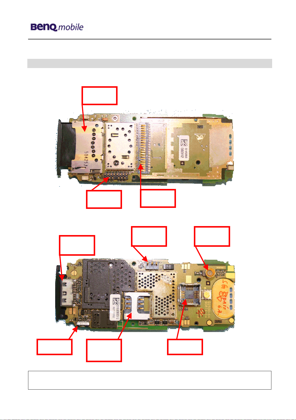
4 S75 Board layout
Upper board side
Lower board side
IRDA
IO Jack
Slim
Connector
MMC
MMI
Connector
Connector
SIM Card
Reade
Connector
Display
Connector
Battery
Connector
Connector
Antenna
Technical Documentation
TD_Repair_L2.5L_S75_R1.0.pdf Page 5 of 15
Company Confidential
2005©BenQ
10/2005
Page 6

Release 1.0
y
y
r
g
y
y
5 SIM Card Problems
Fault Symptoms
Customer: GRT:
Handset does not accept SIM card SIM Card Problems
SIM Card Problems
Watch for oxidation and
damaged pads of the
SIM Card reader
okay
Check the status of the
EMI Filter visually
okay
not
oka
Check the status of the
SIM Card reader visually
okay
not
Exchange
SIM Card reade
oka
Connector SIM Card Reader
Use soldering iron to remove defective component. Avoid excessive heat! Watch surrounding
components! Resolder new component afterwards.
E-commerce order number: L50634-Z97-C406
E-commerce order name: CONNECTOR SIM CARD READER R65 (B)
Soldering temperature: ~ 360°C TIP Temp.
EMI Filter
Use hot air blower to remove defective component. Avoid excessive heat! Watch surrounding
components! Resolder new component afterwards.
E-commerce order number: L50620-U6029-D670
E-commerce order name: FILTER EMI (Fi-Type7) PB Free
Soldering temperature: ~ 360°C TIP Temp
IRIS Diagnose Code: 43300 Interface/SIM Card reader/Mechanical Damage
Use the resistor test
function of a multimeter
to check connection
between spring
contacts and soldering
contacts.
The value must be ~0
not
oka
okay
not
oka
Back to customer
without repair
caused by customer
SCRAP - has to be send
separately to WSC
Exchange the
dama
- check for twisted or
bent contacts
- check for dry joints
Continue with
higher repair level
ed Filter
Technical Documentation
10/2005
TD_Repair_L2.5L_S75_R1.0.pdf Page 6 of 15
Company Confidential
2005©BenQ
Page 7

Release 1.0
y
y
r
y
y
6 IO Connector Problems
Fault Symptoms
Customer: GRT:
Charging Problems No connection to GRT
Problems with external loudspeaker or microphone when using a
car kit
Problems with accessories connected at the IO connector
IO connector Problems
Watch for oxidation and
damaged pads of the
IO connector
not
oka
caused by customer
SCRAP - has to be send
okay
not
oka
Check the dust inside
the IO connector
okay
Check the status of the
IO connector visually
okay
not
oka
Clean IO connector
not
Exchange
IO connecto
oka
Connector IO Jack
Use soldering iron to remove defective component. Avoid excessive heat! Watch surrounding
components! Resolder new component afterwards.
E-commerce order number: L36334-Z93-C303
E-commerce order name: IO-JACK SLIM 12-POL
Soldering temperature: ~ 360°C TIP Temp.
IRIS Diagnose Code: 46100 Interface/Charging Connector/Mechanical Damage
Use the resistor test
function of a multimeter
to check connection
between spring
contacts and soldering
contacts.
The value must be ~0
47300 Interface/Data Interface/Mechanical Damage
4B100 Interface/Headset Connector/Mechanical Damage
okay
higher repair level
Back to customer
without repair
separately to WSC
- check for twisted or
bent contacts
- check for dry joints
Continue with
Technical Documentation
10/2005
TD_Repair_L2.5L_S75_R1.0.pdf Page 7 of 15
Company Confidential
2005©BenQ
Page 8

Release 1.0
Important additional soldering hints
The MMC Reader is located on the opposite of the SLIM-Lumberg connector.
Therefore the risk to damage the plastic material of this MMC-Reader is potentially high if excessive
heat is used while removal or soldering of the SLIM-Lumberg connector.
Please follow these instructions:
a) Remove the SLIM-Lumberg connector with a soldering iron and Desolder Wick
b) Clean the Pads afterwards
c) Solder the new connecter by using soldering iron under consideration of the max. allowed
temperature range.
Samples of critical area:
Lock mechanism damaged Lock mechanism OK
Lock mechanism damaged Lock mechanism OK
Technical Documentation
10/2005
TD_Repair_L2.5L_S75_R1.0.pdf Page 8 of 15
Company Confidential
2005©BenQ
Page 9

Release 1.0
y
y
y
7 B to B connector (upper slider part) Problems
not
oka
Back to customer
without repair
caused by customer
SCRAP - has to be send
separately to WSC
- check for twisted or
bent contacts
- check for dry joints
Fault Symptoms
Customer: GRT:
Upper slider keyboard malfunction Keyboard malfunction
Upper slider keypad illumination does not work Current measured failed
B to B connector problems
Watch for oxidation and
damaged pads of the
B to B connector
okay
not
oka
Check the status of the
B to B connector visually
okay
Exchange
B to B
connector
not
oka
Continue with
higher repair level
Connector Board to Board
Use hot air blower to remove defective component. Avoid excessive heat! Watch surrounding
components! Resolder new component afterwards.
E-commerce order number: L50634-Z97-C340
E-commerce order name: BOARD TO BOARD 30-POL
Soldering temperature: ~ 360°C TIP Temp.
IRIS Diagnose Code: 32100 Keys / Main / No Function
32200 Keys / Main / Reduced Functionality
36000 Keys / Illumination
Technical Documentation
10/2005
TD_Repair_L2.5L_S75_R1.0.pdf Page 9 of 15
Company Confidential
2005©BenQ
Page 10

Release 1.0
y
y
y
y
8 Battery Connector Problems
Fault Symptoms
Customer: GRT:
Mobile does not switch on No connection to GRT
Battery connector problems
Back to customer
without repair
Watch for oxidation and
damaged pads of the
battery connector
not
oka
caused by customer
okay
SCRAP - has to be send
separately to WSC
not
oka
Check the status of the
battery connector
visuall
- check for twisted or
bent contacts
- check for dry joints
okay
Exchange
battery
connector
not
oka
Use the resistor test
function of a multimeter
to check connection
between spring
contacts and soldering
contacts. The value
must be ~ 0.
okay
Continue with
higher repair level
Connector BATTERY
Use hot air blower to remove defective component. Avoid excessive heat! Watch surrounding
components! Resolder new component afterwards.
E-commerce order number: L36334-Z97-C213
E-commerce order name: CONNECTOR BATTERY 3-POL
Soldering temperature: ~ 360°C TIP Temp.
IRIS Diagnose Code: 13000 Battery/Mechanical Damage
Technical Documentation
10/2005
TD_Repair_L2.5L_S75_R1.0.pdf Page 10 of 15
Company Confidential
2005©BenQ
Page 11

Release 1.0
y
y
y
9 MMC Connector Problems
Fault Symptoms
Customer: GRT:
MMC malfunction Tbd.
MMC connector Problems
Watch for oxidation and
damaged pads of the
MMC connector
not
oka
okay
not
oka
Check the status of the
MMC connector visually
Exchange
MMC connector
not
oka
Use the resistor test
function of a multimeter
to check connection
between spring
contacts and soldering
contacts.
The value must be ~0
okay
Connector MMC
Use soldering iron to remove defective component. Avoid excessive heat! Watch surrounding
components! Resolder new component afterwards.
E-commerce order number: L50634-Z97-C415
E-commerce order name: CONNECTOR RS MMC X75; CONNECTOR RS MMC X75
Soldering temperature: ~ 360°C TIP Temp.
IRIS Diagnose Code: 4E000 Interfaces/ Memory Card Rerader
Attention: Avoid excessive heat in order not to damage the plastic material of the
connector (see problem SLIM-Lumberg connector)
Back to customer
without repair
caused by customer
SCRAP - has to be send
separately to WSC
- check for twisted or
bent contacts
- check for dry joints
Continue with
higher repair level
Technical Documentation
10/2005
TD_Repair_L2.5L_S75_R1.0.pdf Page 11 of 15
Company Confidential
2005©BenQ
Page 12

Release 1.0
y
y
y
y
10 Camera Connector Problems
not
oka
okay
Back to customer
without repair
caused by customer
SCRAP - has to be send
separately to WSC
- check for twisted or
bent contacts
- check for dry joints
Continue with
higher repair level
Fault Symptoms
Customer: GRT:
Camera malfunction Tbd.
Camera connector Problems
Watch for oxidation and
damaged pads of the
camera connector
okay
not
oka
Check the status of the
camera connector
visuall
Exchange
camera
connector
not
oka
Use the resistor test
function of a multimeter
to check connection
between spring
contacts and soldering
contacts.
The value must be ~0
Connector CAMERA
Use hot air blower to remove defective component. Avoid excessive heat! Watch surrounding
components! Resolder new component afterwards.
E-commerce order number: L50634-Z97-C379
E-commerce order name: CONNECTOR CAMERA-SOCKET
Soldering temperature: ~ 360°C TIP Temp.
IRIS Diagnose Code: BA000 Accessories / Camera
Technical Documentation
10/2005
TD_Repair_L2.5L_S75_R1.0.pdf Page 12 of 15
Company Confidential
2005©BenQ
Page 13

Release 1.0
y
y
y
11 IRDA Problems
not
oka
Back to customer
without repair
caused by customer
SCRAP - has to be send
separately to WSC
- check for twisted or
bent contacts
- check for dry joints
Fault Symptoms
Customer: GRT:
No infrared connection possible Tbd.
IRDA Problems
Watch for oxidation and
damaged pads of the
IRDA
okay
not
oka
Check the status of the
IRDA visually
okay
Exchange
IRDA
not
oka
Continue with
higher repair level
IRDA
Use hot air blower to remove defective component. Avoid excessive heat! Watch surrounding
components! Resolder new component afterwards.
E-commerce order number: L36197-F5008-F492
E-commerce order name: IRDA 115.2 KBIT
Soldering temperature: ~ 360°C TIP Temp.
IRIS Diagnose Code: 41100 Interfaces / IRDA / No Function
41300 Interfaces / IRDA / Mechanical Damage
Technical Documentation
10/2005
TD_Repair_L2.5L_S75_R1.0.pdf Page 13 of 15
Company Confidential
2005©BenQ
Page 14

Release 1.0
y
y
y
y
11 Display Problems
not
oka
okay
Back to customer
without repair
caused by customer
SCRAP - has to be send
separately to WSC
- check for twisted or
bent contacts
- check for dry joints
Continue with
higher repair level
Fault Symptoms
Customer: GRT:
Display problems Current measured failed
Display Problems
Watch for oxidation and
damaged pads of the
Display connector
okay
not
oka
Check the status of the
Display connector
visuall
Connector DISPLAY
Use hot air blower to remove defective component. Avoid excessive heat! Watch surrounding
components! Resolder new component afterwards.
E-commerce order number: L50634-Z97-C380
E-commerce order name: CONNECTOR DISPLAY 20POL
Soldering temperature: ~ 360°C TIP Temp.
IRIS Diagnose Code: 21000 Display / Performance
22000 Display / Background Illumination
Exchange
display
connector
not
oka
Use the resistor test
function of a multimeter
to check connection
between spring
contacts and soldering
contacts.
The value must be ~0
Technical Documentation
10/2005
TD_Repair_L2.5L_S75_R1.0.pdf Page 14 of 15
Company Confidential
2005©BenQ
Page 15

Release 1.0
y
y
r
y
y
12 Main keypad illumination Problems
not
oka
okay
Back to customer
without repair
caused by customer
SCRAP - has to be send
separately to WSC
- check for twisted or
bent contacts
- check for dry joints
Continue with
higher repair level
Fault Symptoms
Customer: GRT:
Main keypad illumination does not work Current measured failed
Led’s Problems
Watch for oxidation and
damaged pads of the
LED’s
okay
not
oka
Check the status of the
battery connector
visuall
Exchange
keypad LED’s
not
oka
Use the diode test
function of a multimete
to check the status of
the diode. The typical
voltage drop on the
diode is 1.7 V when
testing the diode
function with the
multimeter.
LED WHITE TOP
Use soldering iron to remove defective component. Avoid excessive heat! Watch surrounding
components! Resolder new component afterwards.
Attention: Remove Metal Dome Sheet before!!!
E-commerce order number: L36840-L2099-D670
E-commerce order name: LED WHITE TOP
Soldering temperature: ~ 360°C TIP Temp.
IRIS Diagnose Code: 36000 Keys/Illumination
Technical Documentation
10/2005
TD_Repair_L2.5L_S75_R1.0.pdf Page 15 of 15
Company Confidential
2005©BenQ
 Loading...