

Page 1

control
User Guide
KVM series3-1621
Keyboard/Video/Mouse Switch English
3
Page 2
USA Notification
Warning: Changes or modifications to this unit not expressly approved by the party
responsible for compliance could void the user’s authority to operate the equipment.
Note: This equipment has been tested and found to comply with the limits for a Class
A digital device, pursuant to Part 15 of the FCC Rules. These limits are designed
to provide reasonable protection against harmful interference when the equipment
is operated in a commercial environment. This equipment generates, uses and can
radiate radio frequency energy and, if not installed and used in accordance with
the instruction manual, may cause harmful interference to radio communications.
Operation of this equipment is a residential area is likely to cause harmful
interference, in which case the user will be required to correct the interference at his/
her own expense.
Canadian Notification
This Class A digital apparatus complies with Canadian ICES-003.
Cet appareil numérique de la classe A est conforme à la norme NMB-003 du
Canada.
Japanese Notification
Korean Notification
Safety and EMC Approvals and Markings
UL, FCC, cUL, ICES-003, CE, GS, VCCI, MIC, C-Tick, GOST
Safety certifications and EMC certifications for this product are obtained under one
or more of the following designations: CMN (Certification Model Number), MPN
(Manufacturer’s Part Number) or Sales Level Model designation. The designation
that is referenced in the EMC and/or safety reports and certificates are printed on the
label applied to this product.
Page 3

KVM s3-1621 and s3-1641
User Guide
Edition July 2007
Page 4

Comments... Suggestions... Corrections
The User Documentation Department would like to know your opinion of this manual.
Your feedback helps us optimize our documentation to suit your individual needs. Fax
forms for sending us your comments are included in the back of the manual. There you
will also find the addresses of the relevant User Documentation Department.
Certified documentation
according to DIN EN ISO 9001:2000
To ensure a consi stently high qual ity stand ard and us er-friendli ness, thi s documenta tion
was created to meet the regulations of a quality management system which complies
with the requirements of the standard DIN EN ISO 9001:2000.
Copyright and Trademarks
Copyright © 2006 Fujitsu Siemens computers GmbH.
All rights reserved.
Delivery subject to availability; right of technical modifications reserved.
All hardware and software names used are trademarks of their respective
manufacturers.
This manual is printed on
paper treated with
chlorine-free bleach.
Page 5

Contents
Contents
1 Product overview ....................................................................................1
1.1 Glossary....................................................................................................1
1.2 Notational Conventions.............................................................................1
1.3 Features and benefits................................................................................2
1.3.1 KVM-IA Intelligent Adapters......................................................................3
1.3.2 Virtual Media .............................................................................................4
1.3.3 OSCAR graphical user interface ...............................................................4
1.3.3.1 Security .....................................................................................................4
1.3.3.2 Operation modes.......................................................................................4
1.3.4 Video.........................................................................................................4
1.3.5 Flash upgradability....................................................................................5
1.3.6 Accessing the appliances through a network connection..........................5
1.3.7 Accessing target devices...........................................................................5
1.3.8 On-board web interface.............................................................................5
2 Installation ...............................................................................................7
2.1 Installation overview..................................................................................7
2.1.1 Installing a KVM s3-1621 or KVM s3-1641 appliance...............................7
2.1.2 Setting up the network...............................................................................8
2.2 Required items.............. ..... .................................. ...... ..... ..........................9
2.3 Safety precautions.....................................................................................9
2.3.1 General......................................................................................................9
2.4 Rack mounting a KVM appliance............................................................10
2.4.1 General guidelines..................................................................................10
2.4.2 Installing a KVM appliance in the rack mounting space..........................11
2.5 Connecting the KVM applianc e hardwa re................................... ............12
2.5.1 Connecting a KVM-IA to each target device............................................12
2.5.2 Connecting local peripheral devices........................................................12
2.6 Verifying Ethernet connections................................................................13
2.7 Configuring the KVM s3 Client...............................................................13
2.8 Adjusting mouse settings ........................................................................13
2.9 Attaching earlier app liance models to a KVM s3-1621 or s3-1641 appli ance
13
2.9.1 Attaching an incompatible switch model..................................................14
2.10 Setting up the KVM s3-1621 and
KVM s3-1641 appliances15
3 Basic operations .......................................... ...... ...................................17
3.1 Controlling the switching system from the analog port............................17
3.2 Starting the OSCAR interface .................................................................17
590-591-609B
Page 6

Contents
3.3 Setting a screen delay.............................................................................19
3.4 Connecting a user to a target device..................................... ..................19
3.5 Selecting the previously selected target device.......................................19
3.6 Disconnecting the user from a target device...........................................19
3.7 Using the OSCAR interface.....................................................................20
3.8 Connecting local virtual media.................................................................21
3.9 Configuring the appliances and the OSCAR interface............................22
3.9.1 Assigning target device names ...............................................................23
3.9.2 Assigning appliance and device types ....................................................25
3.9.2.1 Accessing the Devices window...............................................................25
3.9.2.2 Assigning a switch type...........................................................................26
3.9.3 Changing the display behavior................................................................26
3.9.3.1 Selecting the order of the target devices.................................................27
3.9.3.2 Select, complete the following steps.......................................................27
3.9.3.3 Setting up a screen delay........................................................................27
3.9.4 Selecting the display language................................................................28
3.9.5 Controlling the status flag........................................................................28
3.9.6 Setting the keyboard country code..........................................................30
3.9.7 Setting KVM s3-1621 and KVM s3-1641 appliancesecurity...................31
3.9.7.1 Enabling the screen saver.......................................................................31
3.9.7.2 Disabling the screen saver......................................................................31
3.9.7.3 Setting or change a password.................................................................31
3.9.7.4 Recovering a password...........................................................................32
3.9.7.5 Disabling password protection.................................................................32
3.10 Setting the preemption warning...............................................................32
3.11 Managing target device tasks using the OSCAR interface......................33
3.11.1 Accessing the Commands window..........................................................34
3.11.2 Displaying version information.................................................................34
3.11.3 Upgrading the firmware...........................................................................35
3.11.4 Viewing the display configuration............................................................36
3.11.5 Viewing and disconnecting user connections..........................................36
3.11.5.1 Viewing current user connections............................................................36
3.11.5.2 Disconnecting a user...............................................................................37
3.11.6 Resetting the keyboard and mouse values............................................38
3.12 Scanning the switching system...............................................................39
3.12.1 Adding target devices to the scan list......................................................39
3.12.2 Removing a target device from the scan list............................................40
3.12.3 Starting the scan mode...........................................................................40
3.12.4 Canceling scan mode..............................................................................41
3.13 Running switching syst em dia gno st ic tes ts.............................................41
590-591-609B
Page 7

Contents
4 Computer terminal operations.............................................................43
4.1 The Console menu..................................................................................43
4.1.1 Configuring network settings...................................................................43
4.1.2 Configuring network speed settings........................................................44
4.1.3 Other Console Main menu options..........................................................45
4.1.3.1 Security Configuration.............................................................................45
4.1.3.2 Firmware Management............................................................................45
4.1.3.3 Enable Debug Messages ........................................................................45
4.1.3.4 Restore Factory Defaults.........................................................................45
4.1.3.5 Reset the KVM s3-1621 or KVM s3-1641 appliance...............................45
4.1.3.6 Exit ..........................................................................................................45
5.1 Flash upgrades........................................................................................47
5.1.1 Upgrading the firmware using the KVM s3 Client....................................47
5.1.2 Upgrading the firmware using the Console menu...................................47
5.1.3 Repairing damaged firmware ..................................................................48
5.2 Virtual media ...........................................................................................48
5.2.1 Virtual media and USB 2.0 constraints....................................................48
5.2.2 Booting a computer using virtual memory...............................................49
5.2.2.1 Determining if your computer can be booted from virtual media.............49
5.2.2.2 Virtual media restrictions.........................................................................50
5.3 UTP cabling........................ ...... ...... ..... ...... ....................................... .......50
5.3.1 UTP copper cabling......................................................... ........................50
5.3.2 Wiring standards .....................................................................................51
5.3.3 Cabling installation, maintenance, and safety tips...................................51
5.4 Technical specifications ..........................................................................52
5.5 Technical Support ...................................................................................54
5.5.1 Before you call.........................................................................................54
590-591-609B
Page 8

Contents
590-591-609B
Page 9

1 Product Overview
The KVM s3-1621and the KVM s3-1641 appliances integrate digital and analog
keyboard, video, and mouse (KVM) switching technology with advanced cable
management, access for two or four simultaneous users, and a user interface. The
appliances have USB and PS/2
device platforms.
1.1 Glossary
The following terms are used throughout this document:
• ACI Port - ACI stands for “analog console interface ”. Th is is a po rt on some Fujitsu
Siemens KVM switches that acts as an integrated KVM-IA adapter for tiering
purposes.
• ARI Port - ARI stands for “analog rack interface”. The ARI Port is used to connect
computers and KVM switches to KVM series2 and series3 KVM switches via a
KVM-IA adapter.
• KVM s3-1621 and KVM s3-1641 appliances - equipment that provides KVM-over-
IP connectivity to attached target devices. The term appliance is used in this
manual to refer to a KVM switch managed by the KVM s3 Client.
• KVM-IA - (Keyboard/Video/Mo use-Interfa ce Adapter) - adapte r that, wh en attache d
to the appliance and a target device, provides additional functionality, such as
virtual media sessions
• switching system - a set of appliances and attached target devices and KVM-IAs
• target device - equipment such as a server or router that is attached to
an appliance by a KVM-IA
• local user - person with access to the keyboard, monitor, and mouse directly
connected to the appliance. This user has full acc es s to all t arg et dev ice s.
• remote user - an account in the local appliance user database or on a centralized
Active Directory server. This account is used to provide management access to an
appliance and its attached devices.
• virtual media - a USB media device that can be attached to the KVM s3-1621 and
KVM s3-1641 applian ces and made av ailable to any tar get devic e that is co nnected
to a KVM s3-1621 or KVM s3-1641 appliance
®
ports on the rear panel that support all major target
1.2 Notational Conventions
The following notational conventions are used in this manual:
Bold This indicates emphasis in the text.
Key This indicates keys or key combinations in continuous text.
Italics This indicates commands, file names, menu names, and
inputs in continuous text.
This indicates additional information and tips.
590-591-609B
1
Page 10
Product Overview
e
Titl
This indicates a step that you have to perform.
- and • These characters symbolize itemized lists.
Bold monospace font This indicates user inputs in examples.
This indicates information, which if not heeded, may
jeopardize your health, the functioning of your system, or
the security of your data.
1.3 Features and benefits
The KVM s3-1621 and KVM s3-164 1 appliances are rack-moun table KVM switc hes that
are configurable for analo g (loc al ) or digit al (rem ote ) con nec tiv ity . Vide o res olu tio ns are
supported up to 1280 x 1024 for remote users.
The KVM s3-1621 appliance includes two digital port sets for KVM-over-IP access, 1
analog port set for KVM access, 16 analog rack interface (ARI) ports for connecting
KVM-IAs and target devices, and virtual media capability for one local user and up to
two remote users.
The KVM s3-1641 appliance includes four digital ports for KVM-over-IP access, 1
analog port set for KVM access, 16 ARI ports for connecting KVM-IAs and target
devices, and virtual media capability for one local user and up to four remote users.
Both appliances can be used with the KVM s3 Client application to view and control
these appliances as well as the legacy KVM series2 (KVM2-1611) appliance and
attached target devices. For more information about the KVM s3 Client, refer to the
Managing KVM Appliances User Guide.
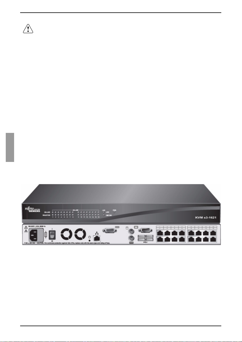
Figure 1: KVM s3-1621 appliance
2
590-591-609B
Page 11
KVM-IA Intelligent Adapters
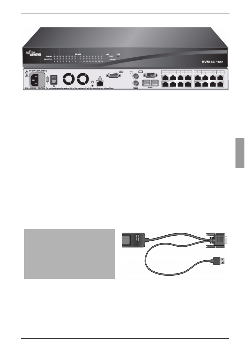
Figure 2: KVM s3-1641 appliance
®
The KVM s3-1621 and KVM s3-1641 appliances have user peripheral ports for PS/2
and USB keyboards and mice. Additionally, virtual media, such as generic removable
media and CD drives, can be connected to any one of four USB ports.
The KVM s3-1621 and KVM s3-1641 appliances work over standard LAN connections.
Users can access target devices across a 1000BASE-T LAN port that is used to
establish an Ethern et connection, or direct ly through a local port. The IP-based KVM s 31621 and KVM s3-1641 appliances give you target device control from anywhere in
the world.
1.3.1 KVM-IA Intelligent Adapters
You can use the following KVM-IAs with the KVM s3-1621 and KVM s3-1641
appliances:
• KVM S2-Adapter PS/2-VGA - PS/2 and VGA connectors
• KVM s2-Adapter SUN-VGA - PS/2 and VGA connectors
• KVM s3-Adapter USB2-VGA - USB2 and VGA connectors, required for virtual
media connections
• KVM s2-Adapter 1.1 USB-VGA - USB and VGA connectors
PS/2 and VGA connectors KVM s3-Adapter USB2-VGA
Figure 3: Examples of KV M-IAs
These intelligent KVM-IAs with Cat 5 design dramatically reduce cable clutter while
providing optim al digita l displa y resolu tion and video se ttings. Th e built-i n memory of the
KVM-IA simplifies configuration by assigning and retaining unique target device
identification codes for each attached target device. This integrated intelligence
enhances security and prevents unauthorized access to a target device through cable
590-591-609B
3
Page 12

Product Overview
manipulation. Th e KVM-IA is pow ered d irectly f rom the ta rget de vice an d prov ides Keep
Alive functionality when the KVM s3-1621 or KVM s3-1641 appliance is not turned on.
The KVM-IAs enable direct KVM connectivity to target devices that are attached to the
KVM s3-1621 or KVM s3-1641 appliance. Each KVM s3-1621 and KVM s3-1641
appliance has 16 ARI ports for connecting KVM-IAs.
The KVM-IAs that work with the appliances support target devices with PS/2 and USB
ports as well as SUN 8-pin ports for keyboard and mouse. When using the OSCAR
interface in conjunction with KVM-IAs, you can easily switch between platforms.
1.3.2 Virtual Media
The KVM s3-1621 and KVM s3-16 41 appliances support virtual med ia w he n co nn ect ed
to a KVM-IA. You can use virtual media support to connect USB media devices to a
KVM s3-1621 or KVM s3-1641 appliance and make those devices available to any
connected appliances.
Use virtual media to move data between a target device and USB media devices that
are connected to the KVM s3-1621 and KVM s3-1641 appliances. You can install,
upgrade, or recover the operating system; update the BIOS code; or start the target
device from a USB drive through the virtual media capabilities of the KVM s3-1621 and
KVM s3-1641 appliances.
Virtual media can be connected directly to the KVM s3-1621 and KVM s3-1641
appliances using one of four USB ports on these appliances. In addition, virtual media
can be connected to any remote workstation that is running the KVM s3 Client and is
connected to the appliance using an Ethernet connection. To open a virtual media
session with a target device, the target device must first be connected to the appliance
using a KVM s3-Adapter USB2-VGA cable. For more information about the on-board
web interface, refer to the Virtual Media Guide.
1.3.3 OSCAR graphical user interface
The KVM s3-1621 and KVM s3-1641 appliances use the OSCAR® for Fujitsu-Siemens
Computers graphica l user interf ace, which h as menus to c onfigure the switchi ng syste m
and to select computers. You can list target devices by unique name, EID (Electronic
ID), or port number.
1.3.3.1 Security
Use the OSCAR interface to protect the switching system with a screen saver
password. After a user-defined time, the screen saver mode engages and access is
prohibited until the correct password is entered to reactivate the switching system.
1.3.3.2 Operation modes
The OSCAR user in terfa ce pro vi des v ario us operation modes for s yst em administration
of the KVM s3-1621 and KVM s3-1641 appliances. Use these modes (Scan, Switch,
and Share) to manage the switching activities. See Chapter 3, “Basic operations”,
beginning on page 17 for more information.
1.3.4 Video
The KVM s3-1621 and KVM s3-1641 appliances provide optimal resolution for analog
VGA, SVGA, and XGA video. You can achieve resolutions of up to 1280 x 1024
4
590-591-609B
Page 13

Flash upgradability
depending upon th e length of cable that is sepa rating t he KVM s3-1 621 or KVM s3-1641
appliance and target devices.
1.3.5 Flash upgradability
Upgrade the KVM s3-1621 and KVM s3-1641 appliances at any time through the
network port to ensure the KVM s3-1621 or KVM s3-1641 appliance is always running
the most current available version. See Appendix 5.1 on page 47 for detailed
information.
1.3.6 Accessing the appliances through a network connection
Users access the KVM s3-1621 and KVM s3-1641 appliances and all attached target
devices through the Ethernet from a client computer. A c lient computer can be
anywhere a va lid network connection exists.
1.3.7 Accessing target devices
When you access the KVM s3 Client, a listing of all target devices you have permission
to view and manage opens. When you select a target device from the list, the video of
the selected target device opens in a Video Viewer window.
1.3.8 On-board web interface
The on-board web interface provides similar management functions as the KVM s3
Client, but does not require a software server or any installation. The on-board web
interface is launched directly fro m the applianc e, and any s ervers connec ted to the KVM
s3-1621 and KVM s3-1641 appliances are automatically detected. You can use the onboard web interface to configure KVM s3-1621 and KVM s3-1641 appliances from a
web browser. Launch the Viewer fro m the on-b oard web inte rface to es tabli sh KVM and
virtual media sessions to target devices. For more information about the on-board web
interface, refer to the M an agi ng KVM Appl ian ce s User Gu ide.
590-591-609B
5
Page 14
Product Overview
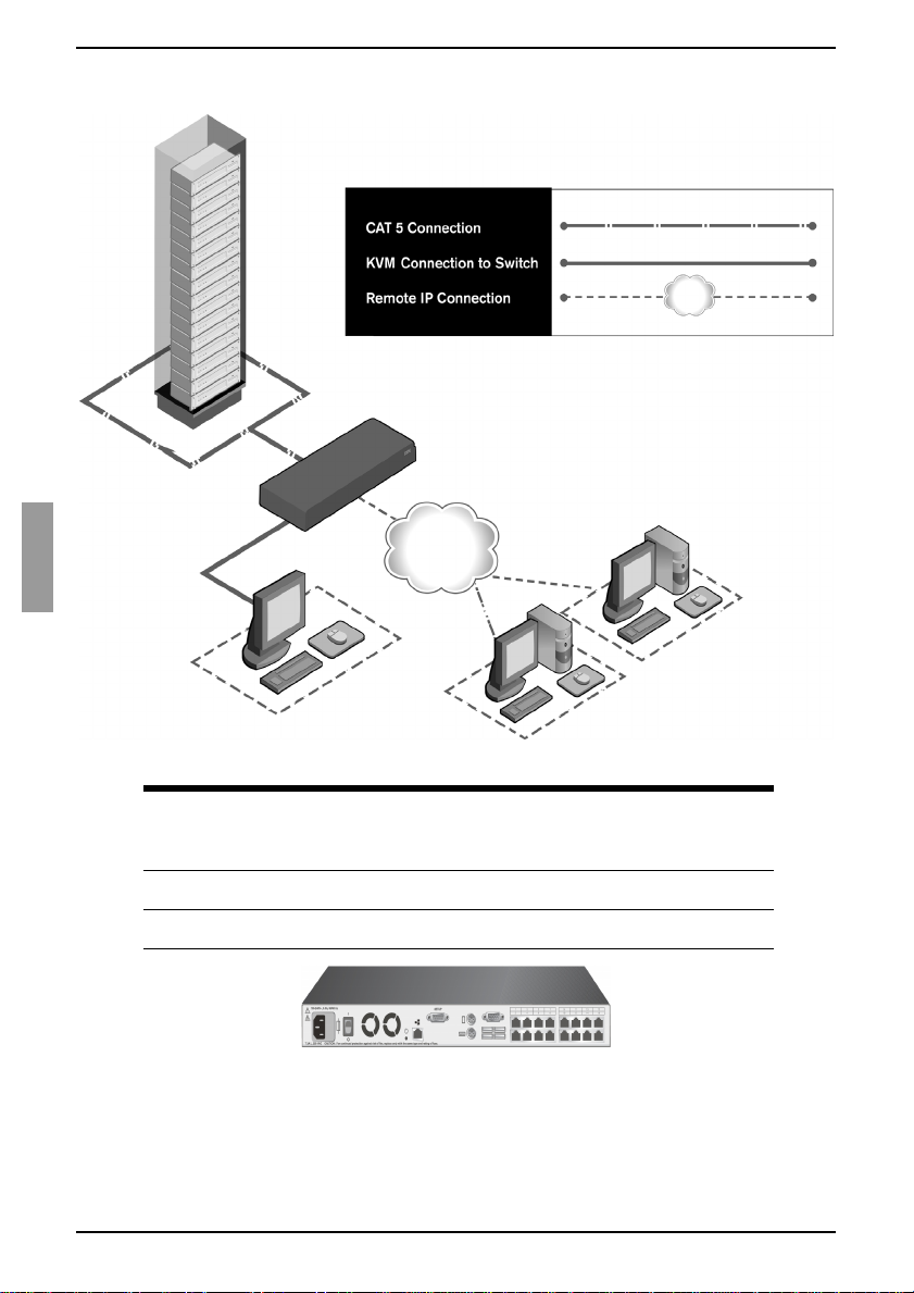
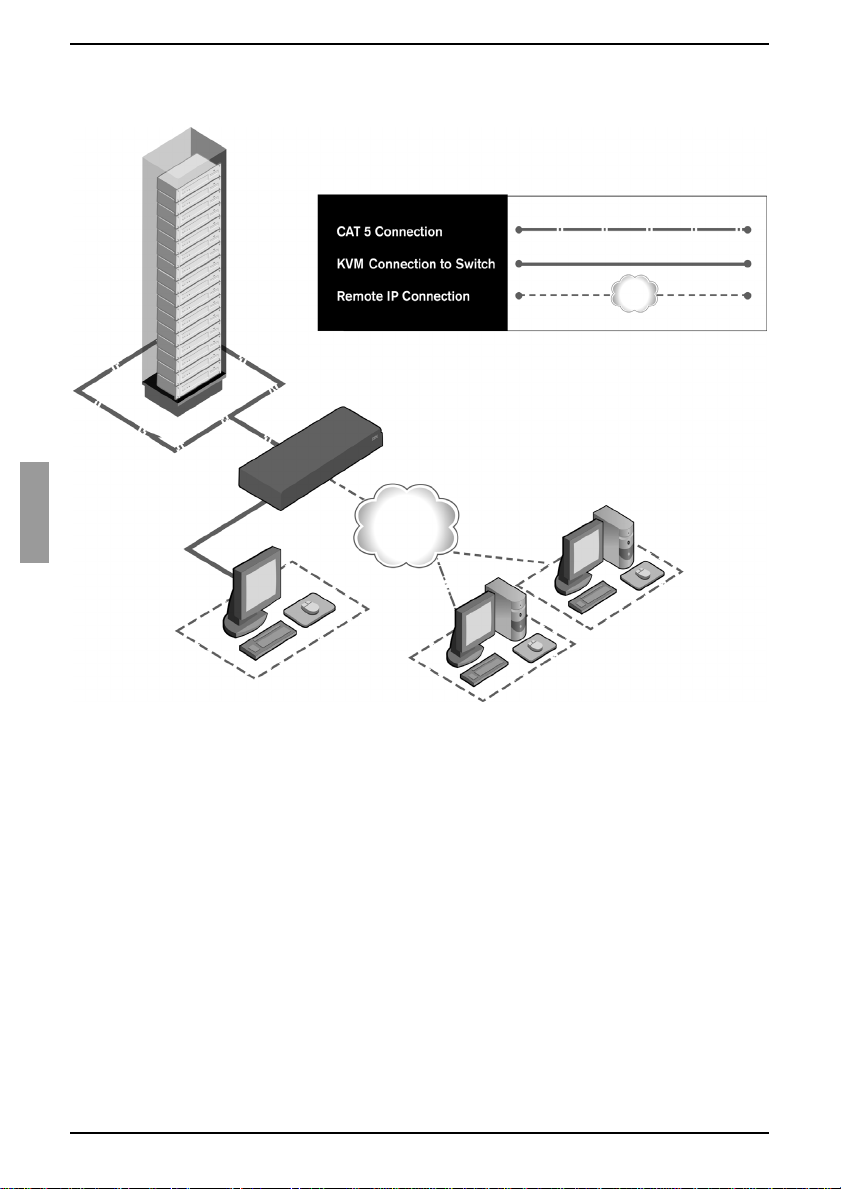
Figure 4 illustrates a typical KVM s3-1621 or KVM s3-1641 appliance configuration.
Rack of
target servers
KVM s3-1621 or KVM s3-1641
appliance
Ethernet
Digital user
Analog user
Digital user
Figure 4: Example KVM s3-1621 or KVM s3-1641 appliance configuration
Local virtual
KVM appliance
models
s3-1621 16 2 1 1 2
s3-1641 16 4 1 1 4
Number of
ARI ports
Digital
paths
Analog
user
media
sessions
Remote
virtual media
sessions
Figure 5: KVM s3-1621 and KVM s3-1641 appliance model comparison
6
590-591-609B
Page 15

2Installation
The KVM s3-1621 and KVM s3-1641 appliances require connectivity to a computer
running the KVM s3 Client. Use the KVM s3 Client to view and control target devices
(one at a time) attached to a KVM s3-1621 or KVM s3-1641 appliance. The analog port
does not require the KVM s3 Client for operation. The analog port uses OSCAR for the
Fujitsu Siemens graphical user interface. For more information, see Chapter 3, “Basic
operations”, beginning on page 17, or the KVM s3 Client User Guide.
The KVM s3-1621 and KVM s3-1641 appliances transmit KVM information between
operators and target devices attached to another appliance over a network using either
an Ethernet or local connec tion.
The KVM s3-1621 and KVM s3-1641 appliances use TCP/IP for communication over
Ethernet. Although 10BASE-T Ethernet can be used, using a dedicated, switched
100BASE-T network or a 1000BASE-T network will improve performance.
2.1 Installation overview
2.1.1 Installing a KVM s3-1621 or KVM s3-1 641 appliance
Unpack the KVM s 3-1621 o r KVM s3-1641 applian ce and ve rify that al l compo nents
are present and in good condition. See section 2.2 Required items on page 9 for
additional information.
Make all hardware connections between the power source, the KVM s3-1621 or
KVM s3-1641 appliance, target devices, KVM-IAs, and Ethernet. See section 2.3
Safety precautions on page 9 for more information.
Turn on the power and verify that all connections are working. See section 2.6
Verifying Ethernet connections on page 13 for instructions.
To configure the KVM s3-1621 or KVM s3-1641 appliance, complete one of the
following steps:
• Use the console menu interface to configure the KVM s3-1621 or
KVM s3-1641 appliance. See Chapter 4, “Computer terminal operations”,
beginning on page 43 for instructions.
-or-
• Use the KVM s3 Client to configure the KVM s3-1621 or KVM s3-1641
appliance. See the KVM s3 Client User Guide for detailed instructions.
Make the needed mouse setting adjustments. See section 2.8 Adjusting mouse
settings on page 13 for instructions.
590-591-609B
7
Page 16
Installation
Figure 6 illustrates one possible configuration for the KVM s3-1621 or KVM s3-1641
appliance.
Rack of
target servers
KVM s3-1621 or KVM s3-1641
appliance
Ethernet
Digital user
Analog user
Figure 6: Example KVM s3-1621 or KVM s3-1641 appliance configuration
Digital user
2.1.2 Setting up the network
The KVM s3-1621 and KVM s3-1641 appliances and KVM-IAs use IP addresses to
uniquely identify the appliances and the target devices. These appliances support both
Dynamic Host configuration Protocol (DHCP) and static IP addressing. To avoid
confusion, have IP addresses that are reserved for each appliance and remain static
while the applia nce s are co nn ect ed to the network. For addi tio nal i nfo rma t ion o n s ett ing
up the KVM s3-1621 and KVM s3-1641 appliances using the KVM s3 Client, and for
information on h ow the KVM s3-1621 and KVM s 3-1641 appli ances use TCP/IP, s ee the
KVM s3 Client Installation and User’s Guide.
8
590-591-609B
Page 17

Required items
2.2 Required items
Before you install a KVM s3-1621 or KVM s3-1641 appliance, make sure that you have
all the required items. The following items come with the KVM s3-1621 and
KVM s3-1641 appliances:
• Power cord (US)
• One serial cable
• Rack-mounting brackets
• KVM s3 Client, Firmware, and Documentation CD
• Quick Installation Guide
In addition to the ite ms that com e with the KVM s 3-1621 or KVM s3-1641 a ppliance, yo u
must provide one KVM-IA (virtual media, KVM, or USB) and one Cat 5 patch cable for
each attached target device or KVM s3-1621 and KVM s3-1641 appliances. A Phillips
and a hex screwdriver is also needed for rack-mounting the KVM s3-1621 and
KVM s3-1641 appliances.
2.3 Safety precautions
Observe the following guidelines to safely operate the equipment.
2.3.1 General
• Observe and follow service markings.
• Do not service any KVM s3-162 1 or KVM s3-1641 appli ance excep t as explain ed in
the KVM s3-1621 and KVM s3-1641 appliance documentation.
• The KVM s3-1621 and KVM s3-1641 appliances contain no serviceable
components. Do not attempt to open the KVM s3-1621 and KVM s3-1641
appliances as doing so may void customer warranty.
• Opening or removing covers t hat are marked with the triangular symbol with a
lightning bolt might expose you to electrical shock. Components inside these
compartments must be serviced only by a trained service technician.
• If any of the following conditions occur, disconnect the KVM s3-1621 or KVM s31641 appliance from th e ele ctri ca l out let an d rep lac e the p art or co ntact the trained
service provider:
• The power c able, extension cable, or connector is damaged.
• An object has fallen into the product.
• The KVM s3-1621 or KVM s3-1641 appliance has been exposed to water.
• The KVM s3-1621 or KVM s3-1641 appliance has been dropped or damaged.
• The KVM s3-1621 or KVM s3-1641 appli anc e doe s not operate properly when
you follow the operating instructions.
• Keep the KVM s3-1621 a nd KVM s3-1 641 applianc es away from ra diators and heat
sources. Also, do not block cooling vents.
• Do not spill food or liquids on the KVM s3-1621 or KVM s3-1641 appliance
components, and never operate the KVM s3-1621 and KVM s3 -164 1 ap pli anc es in
a wet environment. If the KVM s3-1621 or KVM s3-1641 appliance gets wet, see
590-591-609B
9
Page 18

Installation
the applicable section in the troubleshooting guide or contact the trained service
provider.
• Use the KVM s3-1621 an d KVM s3 -1641 a pplia nces only with ap proved equipm ent.
• Operate the KVM s3-1621 or KVM s3-16 41 appliance onl y from the type of ex ternal
power source that is indicated on the elec trical ratings label. If you are not sure of
the type of power source that is required, consult the service provider or local power
company.
• Be sure that the monitor and attached devices are electrically rated to operate with
the power that is available in the current location.
• Use only power cables that are provided with the KVM s3-1621 and KVM s3-1641
appliances.
• To help prevent electric shock, connect the KVM s3-1621 or KVM s3-1641
appliance and peripheral power cables into properly grounded electrical outlets.
These cables are equipped with three-prong connectors to help ensure proper
grounding. Do not use adapter connectors or remove the grounding prong from a
cable.
• Observe extension cable and power strip ratings. Make sure that the total ampere
rating of all products that are connected to the power strip does not exceed 80
percent of the ampere ratings limit for the power strip.
• To help protect the KVM s3-1621 and KVM s3-1641 appliances from sudden,
transient increase s a nd de cre as es in el ec tric al p ow er, use a su rge s upp res so r, line
conditioner, or uninterruptible power supply.
• Carefully position KVM s3-1621 and KVM s3-1641 appliance cables and power
cables. Route cables so that they cannot be stepped on or tripped over. Be sure
that nothing rests on any cables.
• Do not modify power cables or connectors. consult a licensed electrician or the
power company for site modifications. Always follow the local and national wiring
rules.
2.4 Rack mounting a KVM appliance
Before installing the KVM s3-1621 or KVM s3-16 41 applianc e and o ther components in
the rack (if not already installed), stabilize the rack in a permanent location. Install the
equipment start ing a t the bottom of the rack, then work to the top. Avoid uneven loading
or overloading of racks.
2.4.1 General guidelines
• Refer to the rack installation documentation that accompanied t he rack for
specific caution statements and procedures.
• Elevated ambient temperature: In a closed rack assembly, the operation
temperature of the rack environment can be greater than room ambient. Use care
not to exceed the rated maximum ambient temperature of the unit.
• Reduced air flow: Carefully install the equipment in a rack so that an adequate
amount of airflow is maintained for safe operation of the equipment.
10
590-591-609B
Page 19
Installing a KVM appliance in the rack mounting space
• Mechanical loading: Avoid a potentially hazardous condition caused by uneven
mechanical loading by carefully mounting the equipment in the rack.
• Circuit overloading: Consider the connection of the equipment to the supply
circuit and the effect that overloading of circuits might have on overcurrent
protection and supply wiring. Observe equipment nameplate ratings for
maximum current.
• Reliable earthing: Maintain reliable earthing of rack-mounted equipment. Pay
particular attention to supply connections other than direct connections to the
branch circuit (for example, use of power strips).
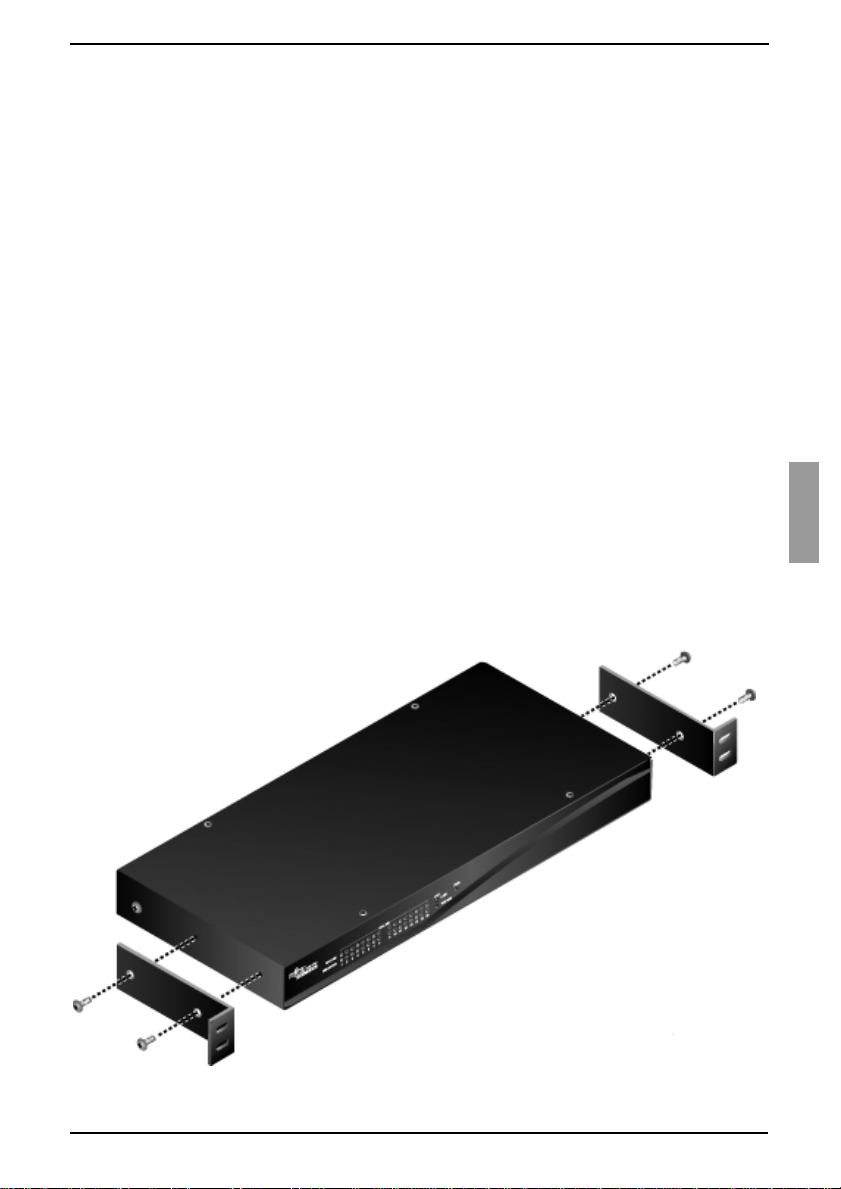
2.4.2 Installing a KVM appliance in the rack
mounting space
Remove the screws on each side of the KVM s3-1621 or KVM s3-1641 appliance.
Line up the holes in the long side of each mounting bracket.
With a Phillips screwdriver, fasten the mounting brackets to the KVM s3-1621 or
KVM s3-1641 appliance, using two 8/32-inch x 1/2-inch pan-head screws on
each side.
Attach four cage nut s or clip nuts to the rack mounting fl ange of the rack so tha t the
nut is positioned on the inside of the rack.
Mount the KVM s3-1621 or KVM s3-1641 appliance assembly to the rack by
matching the holes in the short side of each mounting bracket to a set of matching
holes on the rack. Insert the combination Phillips screws through the slots in the
mounting bracket and the holes in the mounting rail, then into the cage nuts or
clip nuts.
Figure 7: KVM s3-1621 and KVM s3-1641 appliance horizontal installation
590-591-609B
11
Page 20

Installation
2.5 Conn ecting the KVM appliance hardware
Turn of f the t arget devices that are p art of the swi tching sys tem. Conn ect one end of
the power cord to the rear o f the KVM s3-162 1 or KVM s 3-1641 applianc e, and connect the ot her end to an ac power source.
Connect a VGA monitor and either PS/2 or USB keyboard and mouse cables into
the labeled KVM s3-1621 or KVM s3-1641 appliance ports. You must install both a
keyboard and mouse on the local ports or the keyboard will not initialize correctly.
You cannot connect a DVI or EGA monitor to the KVM s3-1621 and KVM s3-1641
appliances.
Connect one end of a Cat 5 p atc h ca bl e (4-p a ir, up to 10 meters) into any ARI port,
and connect the other end into the RJ-45 connector of a KVM-IA.
Connect the KVM-IA into the correct ports on the rear of the target device. Repeat
this procedure f or all t ar get de vice s t hat are to be conn ected to th e KVM s3-1 621 o r
KVM s3-1641 appliance.
Connect a Cat 5 patch cable from the Ethernet network into the LAN port on the
rear panel of the KVM s3-1621 or KVM s3-1641 appliance. Network users will
access the appliance through this port.
If you are configuring the KVM s3-1621 and KVM s3-1641 appliances using the
console menu int erface, c onnect a compute r running terminal emulati on sof tware to
the IOIOI port on the rear panel of the appliance, using the supplied straight serial
cable. The terminal should b e set to 9 600 bit s per se cond (bp s), 8 bit s, 1 s top bit, n o
parity, and no flow control. Otherwise, proceed to the next step.
Turn on each target flag and then turn on the KVM s3-1621 or KVM s3-1641
appliance. After approximately one minute, the appliance completes initialization
and opens the OSCAR graphical user interface Free tag on the local port monitor.
Use the KVM s3 Client to configure your KVM s3-1621 or KVM s3-1641 appliance.
See the KVM s3 Client Installation and User’s Guide for detailed instructions.
2.5.1 Connecting a KVM-IA to each target device
Attach the color-coded connectors of the KVM-IA to the keyboard, monitor, and
mouse ports on the fi rst targe t devic e that yo u conn ect to the KVM s3-16 21 o r KVM
s3-1641 appliance.
Attach one end of the Cat 5 cable to the RJ-45 connector on the KVM-IA.
Connect the other end of t he Ca t 5 ca bl e to an y ARI port on the rear of the KVM s 3-
1621 or KVM s3-1641 appliance.
Repeat steps 1 to 3 for all target devices that you are attaching.
2.5.2 Connecting local peripheral devices
Connect a keyboard, monitor, and mouse to each set of color-coded ports on the
rear of the KVM s3-1621 or KVM s3-1641 appliance.
Bundle and label the cables for easy identification.
12
590-591-609B
Page 21
Verifying Ethernet connections
2.6 Verifying Ethernet connections
The Ethernet conne ction has two LEDs. Th e gree n LED on the right is the Link indicato r.
It is lit when a valid c onnection to the network is estab lished, and it flashes w hen there i s
activity on the port. The amber/green LED on the left indicates that you are
communicating at 100 Mbps (amber) or 1000 Mbps (green) when using the Ethernet
connection.
2.7 Configuring the KVM s3 Client
See the KVM s3 Client Us er Guide included on the CD with the software.
2.8 Adjusting mouse settings
Before a computer connected to the KVM s3-1621 or KVM s3-1641 appliance can
be used for remote user control, you must set the target mouse speed and turn off
acceleration.
If you are experiencing slow mouse response during a remote video session,
deactivate mouse acceleration in the operating system of the target device and set
the mouse speed at 50%.
2.9 Attaching earlier appliance models to a
KVM s3-1621 or s3-1641 appliance
You can add earlier appliance models for integ r ati on i nto the ex ist ing configuration. In a
tiered system, each ARI port will accommodate one target device. When earlier
appliance models are tiered under the KVM s3-1621 or KVM s3-1641 appliance, the
KVM s3-1621 or KVM s3-1641 appliance must be at the top level of the tier. See the
following list for earlier appliance models that are compatible with the KVM s3-1621 or
KVM s3-1641 appliance configuration:
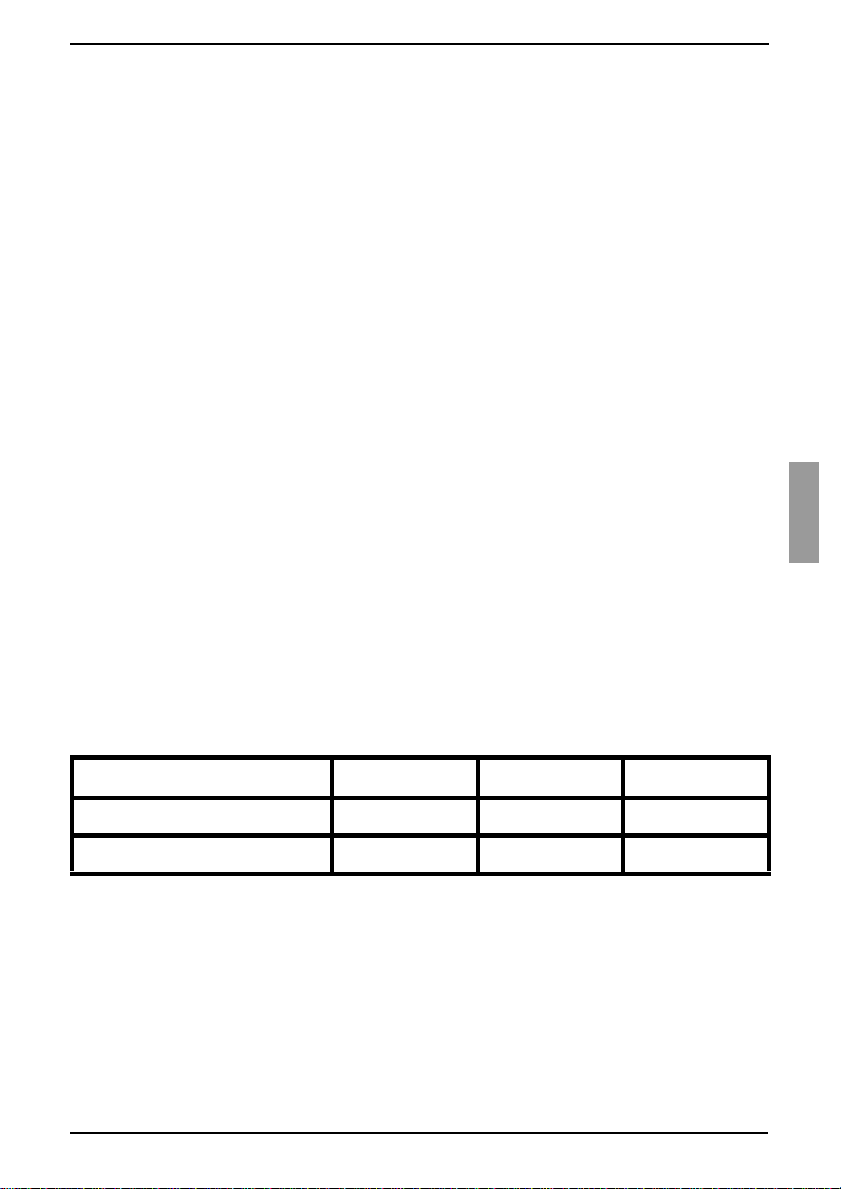
Table 1 lists earlier KVM appliance models.
Earlier appliance model Remote users Local Users ARI ports
KVM s2-0801 (analog) 0 1 8
KVM s2-1602 (analog) 0 1 16
Table 1: Earlier KVM appliance models
Mount the earlier appliance model into the rack according to the instructions that
are included with that appliance.
Perform one of the following actions:
• Attach the keyboard, monitor, and mouse connectors of a KVM-IA to the local
port on the tiered appliance and attach one end of a Cat 5 cable to the end of
the KVM s2-Adapter PS/2-VGA KVM-IA.
-or-
590-591-609B
13
Page 22

Installation
• Attach one end of a Cat 5 cable directly to the Analog Console Interface (ACI)
port on the tiered appliance. (If you are unsure if the appliance being tiered has
an ACI port, please consult the Installer/User guide for the tiered appliance.)
Connect the other end of th e Cat 5 cable to any availa ble ARI port on the rear of the
KVM s3-1621 or KVM s3-1641 appliance.
Turn off and turn on the target devices to the tiered appliances according to the
instructions that are included with that appliance.
Turn off and turn on the tiered appliances to enable its local port to recognize the
KVM-IA.
Repeat steps 1 to 5 for all tiere d applia nces tha t you want to att a ch to the swit ching
system.
The switching system will automatically merge the two appliances. All target devices
that are connected to the tiered appliances are included in the main KVM s3-1621 or
KVM s3-1641 target device list in the OSCAR interface. However, when an earlier
appliance model is connected to a KVM s2-Adapter PS/2-VGA KVM-IA, the list of
appliances in the OSCAR interface will display both the primary KVM s3-1621 or KVM
s3-1641 appliance port number, followed by a dash, and the secondary appliance port
number. For example, the Port column for a secondary earlier appliance model might
display 01-02, where 01 is the primary port and 02 is the secondary port.
2.9.1 Attaching an incompatible switch model
It is possible to attach appliances not listed in the previous table. Incompatible
appliances do not support seamless tieri ng and devices attached to an incompatible
appliance will not be displayed in the OSCAR menu for the KVM s3-1621 or KVM s31641 appliance. Only the name assigned to the incompatible appliance will be
displayed.
To access an incompatible appliance from the KVM s3-1621 or KVM s3-1641:
Activate the OSCAR interface.
Select the incompatible appliance. The OSCAR menu for the incompatible
appliance will display, and all devices that are attached to the appliance will be
shown in the list of devices.
Select your desired device associated with the incompatible appliance.
You are now connected to that device.
To access the KVM s3-1621 or KVM s3-1641 from an incompatible device:
Activate the OSCAR interface.
This will activate the OSCAR interface for both the KVM s3-1621 or KVM s 3-1641 appliance and the
incompatible appliance.
Select the desire devi ce on the OS CAR i nterf ace associ ated wit h th e KVM s3-162 1
or KVM s3-1641 appliance.
14
590-591-609B
Page 23

Setting up the KVM s3-1621 and KVM s3-1641 appliances
2.10 Setting up the KVM s3-1621 and
KVM s3-1641 appliances
With the KVM s3-1621 and KVM s3-16 41 applia nces, you c an auto de tect and c onfigure
each port on the appliance. Chapter 3 provides detailed instructions on naming
customization and OSC AR int erfa ce se tup andconfigurat io n.
590-591-609B
15
Page 24

Installation
16
590-591-609B
Page 25
3 Basic operations
3.1 Controlling the switching system from the
analog port
The KVM s3-1621 and KVM s3-1641 app liances in clude port s on the re ar panel t hat yo u
can use to connect a keyboard, monitor, and mouse to the appliances for direct analog
access. The KVM s3-1621 and KVM s3-1641 appliances use the OSCAR interface,
which has intuitive menus to configure the switching system and select target devices.
Switches can be identified by customizable names.
3.2 Starting the OSCAR interf ace
To view, configure, and control target devices in the switching system from the OSCAR
interface from a KVM connection to the analog port, perform one of the following
actions:
Press Print Screen
-or-
Press the Control
interface.
You can use any of these key sequences instead of pressing Print Screen
procedure in this document. To specify which key sequences can be used to start the
OSCAR interface, click Setup - Menu.
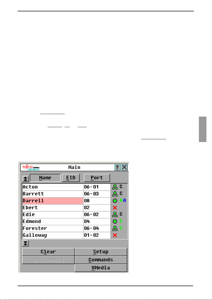
The following illustration is an example of the Main window of the OSCAR interface.
to start the OSCAR interface.
, Alt, or Shift key twice within 1 second to start the OSCAR
in any
Figure 8: Example of a Main window
590-591-609B
17
Page 26
Basic operations
The Main window list s the targe t dev ic es in the sw itching system. You can order the li st
by target device names, EID numbers, or port numbers by clicking the Name, EID, or
Port button.
The Port column indicates the ARI port to which each target device is connected. If an
earlier appliance mode l is con nec te d to a KVM s3-1 621 or KVM s 3-16 41 appl ian ce , the
ARI port number is shown first, followed by the number of the appliance port to which
the target device is connected. For example, in Figure 8 on page 17, the target device
named Acton is connected to ARI port 06 and the appliance to port 01.
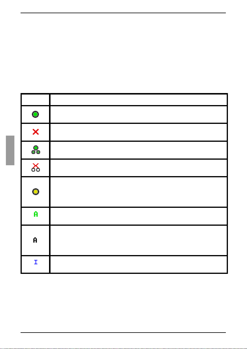
The status of each target device in the switching system is indicated by one or more
status symbols in the right column of the screen. Table 2 describes the status symbols.
Symbol Description
The KVM-IA is online (green circle).
The KVM-IA is offline or is not operating correctly.
The target device is tiered through an earlier appliance model. The target
device and the earlier appliance model is online and has power.
The target device is tiered through an earlier appliance model. The earlier
appliance model is offline or does not have power.
The KVM-IA is being upgrad ed (y el low c ircle). When this symbol is visible,
do not turn off and turn on the appliance or connected target devices and
do not disconnect the KVM-IA. Doing so might damage the KVM-IA
permanently.
The KVM-IA is being accessed by the indicated user channel (green
channel letter).
The KVM-IA is blocked by the indicated user channel (black channel
letter). For instance, in Figure 8 on page 17, user C is viewing Forester,
but is blocking access to Acton, Barrett, and Edie which are connected to
the same KVM-IA.
A virtual media con nec tio n i s e st a bli sh ed to th e target device conne cted to
the indicated user channel (blue letter).
Table 2: OSCAR inter face status symbol s
18
590-591-609B
Page 27
Setting a screen delay
3.3 Setting a screen delay
You can specify the length of time that elapses between when Print Screen is pressed
and when the OSCAR interface starts.
Press Print Screen
In the Main window, click Setup - Menu.
In the Screen Delay Time field, type the number of seconds that you want to
elapse between when Print Screen is pressed and when the OSCAR interface
starts.
to start the OSCAR interface.
3.4 Conn ecting a user to a target device
Use the Main window of the OSCAR interface to select a target device to which you
want to connect. When you select a target device, the keyboard and mouse are
automatically reconfigured to the correct settings for that target device.
Select a target device by pressing Print Screen
then use one of the following procedures:
• In the Main window, double-click the target device name, EID number, or port
number.
-or-
• Type the port number, and press Enter
-or-
• Type the first few characters of the target device name or EID number, and
press Ente r
.
to start the OSCAR interface, and
.
3.5 Selecting the previously selected
target device
You can toggle between two selected target devices by pressing Print Screen and
then press Backspace
.
3.6 Disconnecting the user from a target device
Press Print Screen and press Alt+0. A Free status flag in the OSCAR interface
indicates that the user is not connected to a target device.
590-591-609B
19
Page 28
Basic operations
3.7 Using the OSCAR interface
Table 3 describes the keys, key combinations, and mouse actions that you can use in
the OSCAR interface. Two or more key names or mouse actions that are separated by
commas indicate a sequence of actions. Two or more key names or mouse actions that
are separated by a plus sign (+) indicate a combination of actions; that is, they are
performed simultaneously.
You can use the main keyboard or the numeric keypad to type numerals, except when
you use the Alt
when you use Alt
+0 key combinat ion; y ou mu st use the 0 (ze ro) key on the main keyb oard
+0.
Key, key combination,
Result
or mouse action
Print Screen; Ctrl, Ctrl;
Shift, Shift
Print Screen, Print Screen
F1
Escape
+X Close the current window, without saving changes, and
Alt
Alt
+O Click OK and return to the previous window.
+port number Select a target device to be scanned; port number is the
Alt
; or Alt, Alt
Start the OSCAR interface. To specify which key
sequences can be used to start the OSCAR interface,
click Setup - Menu.
Send the Print Screen keystroke to the currently selected
target device. In other words, a screen capture will be
performed for the target device.
If Print Screen
Setup - Menu, you only need to press Print Screen
to take a screen capture of the target device.
Display help for the current window.
In the OSCAR main window: Clos e the OSC AR interf ac e
and return to the status flag on the desktop.
In all other windows: Close the current window, without
saving changes, and return to the previous window.
In pop-up windows: Close the pop-up window and return
to the current window.
return to the previous window.
port number of the target device.
is not selected as st artu p key sequence in
once
Enter
Table 3: OSCAR inte rface navigation basics
20
Completes a switch in the Main window and exits the
OSCAR interface.
Click on an editable field to select the text for editing and
enable the Left and Right arrow keys to move the cursor.
Press Enter to quit the edit mode.
590-591-609B
Page 29
Connecting local virtual media
Key, key combination,
Result
or mouse action
Print Screen, Backspace R e turn to the previo us ly se lec t ed target dev ic e.
Print Screen, Alt
Print Screen, Pause Start the screen saver immediately and lock the user, if it
Up Arrow
Right Arrow
Page Up
Home or End Move the cursor to the top or bottom of a list.
Delete
Table 3: OSCAR interface navigation basics (Continued)
+0 Disconnect the us er from the selected target device. Note
that the zero must be typed on the main keyboard , not the
numeric keypad.
is password-protected.
or Down Arrow Move the cursor from line to line in a list.
or Left Arro w When editing text in a field: Move within the text in the
field.
All other conditions: Move the cursor from column to
column in a list.
or Page Down Page through a list or help window.
Delete the selected characters in a field or the selected
item in the scan list. For more information about scan
lists, see section 3.12 Scanning the switchi ng syst em on
page 39.
3.8 Connecting local virtual media
You can connect virtual media directly to the KVM s3-1621 and KVM s3-1641
appliances using the USB port on the switches.
All USB ports are assigned to a single virtual media session and cannot be
independently mapped.
Press Print Screen to start the OSCAR interface. The Main window opens.
Connect the user to the target device with which you want to establish a virtual
media session. Use the arrow keys to highlight the target device name, and then
press Ente r
Press Print Screen to start the OSCAR interface again. The Virtual Media window
opens.
590-591-609B
.
21
Page 30
Basic operations
Select one or more of the following check boxes:
• Locked - Select this check box to specify that when the user is disconnected
from a target device, the virtual media is also disconnected.
-or-
• Reserve - Select this check box to specify that the virtual media connection
can be accessed on ly by you r user nam e and that no other user can conne ct to
that target device. If both Locked and Reserved are selected, the session will
be reserved.
-or-
• CDROM - Select this c heck box t o estab lish a virtual media CD co nnection to a
target device. Clear this check box to end the connection.
• Mass Storage - Select this check box to establish a virtual media mass-
storage connection to a target device. Clear this check box to end the
connection.
-or-
• Write Access - Sele ct thi s c he ck box to enable the con nec ted ta rget device to
write data to the virtual media during a virtual media session. Read access is
always enabled during virtual media sessions.
Click OK.
3.9 Configuring the appliances and the
OSCAR interface
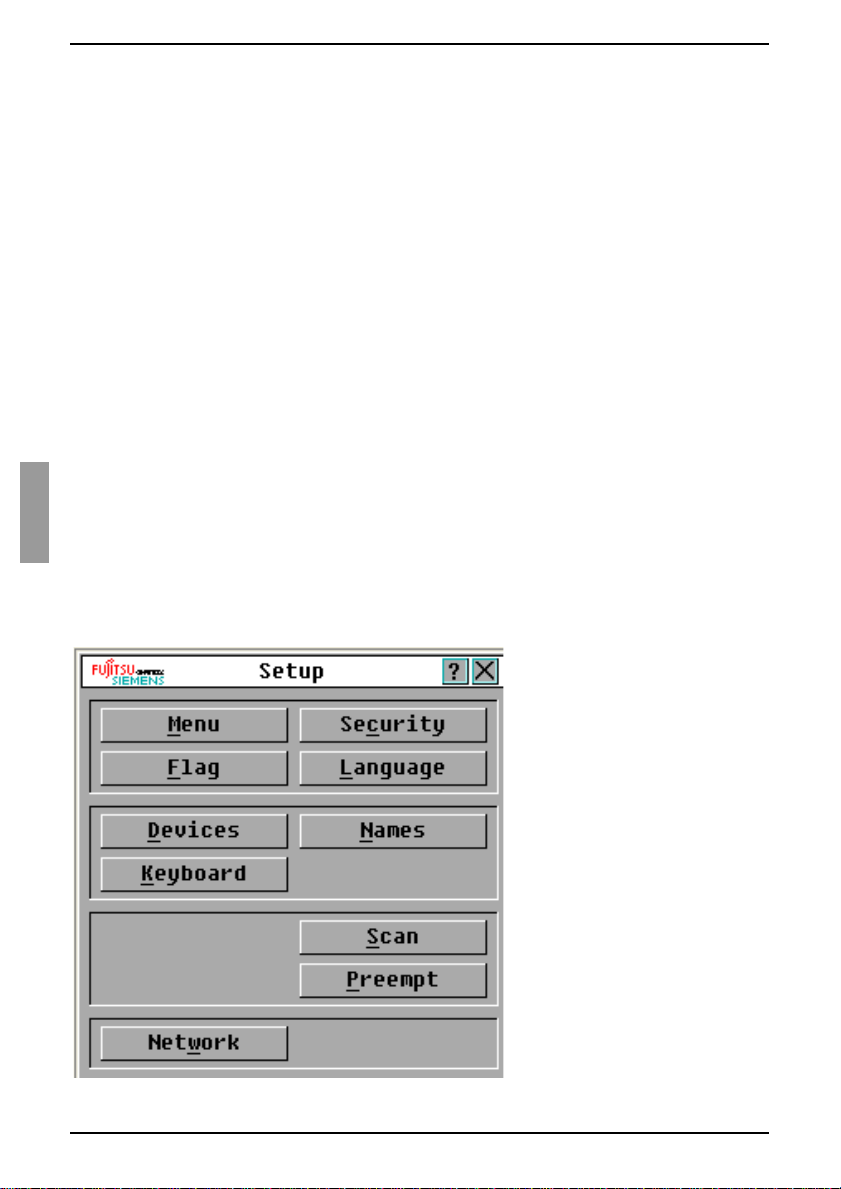
Start the OSCAR interface and click Setup. Figure 9 shows the Setup window.
Figure 9: Setup window
22
590-591-609B
Page 31

Assigning target device names
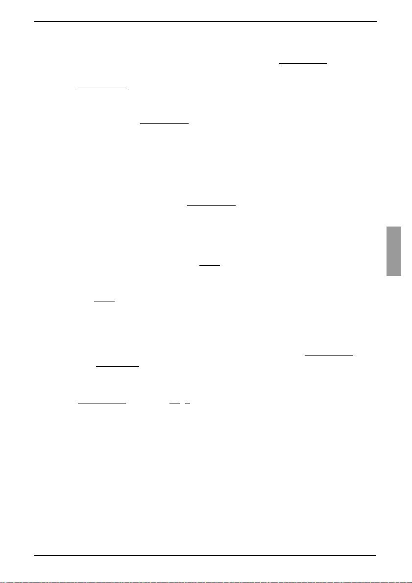
Table 4 describes the options in the Setup window.
Option Purpose
Menu Order the list of target devices by target device name, EID number, or
port number. Set a screen delay to specify the length of time that
elapses between wh en Print Screen is pressed and when the OSCAR
interface starts.
Security Set passwords to restrict access to the target devices. Enable the
screen saver.
Flag Change the displ ay prop erties including timin g, colo r, and location of the
status flag.
Language Specify the language that the interface is displayed in.
Devices Specify the number of ports that are on the att a ch ed tiere d appl ian ce s.
Names Assign a unique name to each target device.
Keyboard Specify the keyboard count ry cod e.
Scan Set up a custom scan pattern for up to 16 target devices.
Preempt Specify preemp tio n setti ngs .
Network Specify the network speed and configuration, IP address, netmask, and
gateway for the switching system.
Table 4: Setup features to manage routine tasks for the target devices
3.9.1 Assigning t arge t device name s
Use the Names window to i den tif y in di vidual target devices by n am e rath er th an b y p ort
number. The Names list is always sorted by port order. Names are stored in the KVMIA, so even if you move the cable or target device to another ARI port, the name and
configuration are recognized by the KVM s3-1621 and KVM s3-1641 appliances. If a
target device is turned off, you cannot modify the name of the KVM-IA.
Press Print Screen
Click Setup - Names. The Names window opens.
590-591-609B
to start the OSCAR interface. The Main window opens.
23
Page 32

Basic operations
Figure 10: N ames window
If new KVM-IAs are discovered by the KVM s3 -162 1 or KVM s3-1 641 appl ia nce , the on-
screen list will automatically be updated. The mouse cursor will change into an
hourglass during the update. No mouse or keyboard input will be accepted until the list
update is complete.
In the Names window, select a target device na me or port nu mber and c lick Modify.
The Name Modify window opens.
Figure 11: Name Modify window
24
590-591-609B
Page 33

Assigning appliance and device types
Type a n ame i n the New Name field. Names of targe t devi ces can b e up to 15
characters long. Valid characters are A through Z, a through z, 0 through 9, space,
and hyphen.
Click OK to transfer the new name to the Names window. The selection is not
saved until you click OK in the Names window.
Repeat steps 1 to 3 for each target device in the switching system.
Click OK in the Names window to save the changes, or click X or press Escape
exit without saving changes.
If a KVM-IA has not been as si gn ed a na me , the EID is used as the de fault name. To list
target devices alphabetically by name, press Alt
+N or click Name in the Main window.
to
3.9.2 Assigning appliance and device types
The KVM s3-1621 and KVM s3-1641 appliances automatically discover attached tiered
appliances, but you must specify the number of ports on the tiered appliances through
the Devices window. Fujitsu Siemens console switches and other earlier appliance
models are listed in the Type category for the tiered appliances. When you select a
configurable appliance from the list, the Modify button becomes available, so you can
assign it the correct number of ports.
3.9.2.1 Accessing the Devices window
Press Print Scree
Click Setup - Devices. The Devices window opens.
n to start the OSCAR interface. The Main window opens.
Figure 12: Devices window
When the KVM s3-1621 or KVM s3-1641 appliance discovers a tiered appliance, the
port numbering changes to accommodate each target device under that appliance.
590-591-609B
25
Page 34
Basic operations
For example, if the earlier appliance model is connected to ARI port 6, the earlier
appliance model port is listed as 06, and the target devices that are under it are
numbered sequentially as 06-01, 06-02, and so on.
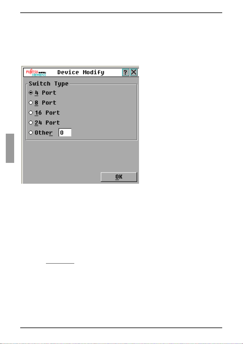
3.9.2.2 Assigning a switch type
In the Devices window, select the port number.
Click Modify. The Device Modify window opens.
Figure 13: Device Modify window
Select or type the numb er of p orts that a re sup por ted by th e tiere d earlier a pplia nce
model and click OK.
Repeat steps 1 to 3 for each port for which you want to assign a switch type.
Click OK in the Devices window to save settings.
3.9.3 Changing the display behavior
Use the Menu window to change the order of the target devices and set a screen delay
for the OSCAR interface. The display order setting affects the order in which target
devices are listed in several windows, including the Main and Devices windows.
Press Print Screen
Click Setup - Menu. The Menu window opens.
26
to start the OSCAR interface. The Main window opens.
590-591-609B
Page 35

Changing the display behavior
Figure 14: Menu window
3.9.3.1 Selecting the order of the target devices
Click one of the following buttons:
•Select Name to list the target devices alphabetically by target device name.
-or-
•Select EID to list the target devices numerically by EID number.
-or-
•Select Port to list the target devices numerically by port number.
Click OK.
3.9.3.2 Select, complete the following steps
In the Invoke OSCAR section, select which key combinations you want to use to
start the OSCAR interface, th en press your selected combination on the keyboar d.
Click OK.
3.9.3.3 Setting up a screen delay
You can set a screen delay so that you can select a target device using the keyboard
without starting the OSCAR interface. A screen delay specifies the length of time that
elapses between when Print Screen is pressed and when the OSCAR interface starts.
Type the numb er of seco nds (0 thro ugh 9) to sp ecify the length of time tha t ela pses
between when Print Scr een
is pressed and wh en the OSCA R interfac e sta rts. If you
specify 0, there is no delay.
Click OK.
590-591-609B
27
Page 36

Basic operations
3.9.4 Selecting the display language
Use the Setup window to change the disp lay l angua ge for the OSC AR i nterface.
Figure 15: Language window
Press Print Screen
Click Setup - Language. The Language window opens.
In the Language window, select the language and click OK.
to start the OSCAR interface. The Main window opens.
3.9.5 Controlling the status flag
The status flag is display ed on the d esktop a nd indica tes the na me or EID num ber of the
selected target de vice or the st atus of the se lecte d port. Yo u can speci fy the i nforma tion
that is displayed in the flag, the flag color, whether the desktop is visible through the
flag, whether the flag is displayed all the time, and where the flag is displayed on the
desktop. Table 5 shows examples of status flags.
Status Flag Description
Flag type by name.
Flag type by EID number.
Flag indicating that th e user has been disconnected from all
systems.
Table 5: OSCAR interface status fla gs
Press Print Screen
28
. The Main window opens.
590-591-609B
Page 37

Controlling the status flag
Click Setup - Flag. the Flag Setup window opens.
Figure 16: Flag Setup window
Set one or more of the following settings:
•Select Name or EID to specify the information that is displayed in the flag.
•Select Displayed to di sp lay t he fla g all the time, or selec t Timed to display the
flag for only 5 seconds after you select a target device.
• In the Display color section, select the flag color.
•Select Opaque to make the flag solid, or select Transparent to make the
desktop visible through the flag.
• To specify the position of the flag, complete the following steps:
• Click Set Position.
• Hold down the left mouse button on the title bar of the Set Position window, and drag the window to the new location.
• Press the right mouse button to close the Set Position window.
Figure 17: Set Position window
Click OK to save the changes, or clic k X or press Escape
changes.
590-591-609B
to exit without saving the
29
Page 38
Basic operations
3.9.6 Setting the keyboard country code
By default, the KVM s3-1621 and KVM s3-1641 appliances send the US keyboard
country code to USB cables attached to target devices, and the code is applied to the
target devices when they are turned on or rebooted. Codes are then stored in the
KVM-IA. Using a keyboard code that supports a language different from that of the
KVM s3-1621 and KVM s3-1641 appliance firmware will cause incorrect keyboard
mapping.
If multiple keyb oards a re conn ected to the l ocal p ort, the y must be of t he same t ype (PC
or Mac) and of the same language .
Issues might arise when you use the US keyboard country code with a keyboard of
another country. For example, the Z key on a US keyboard is in the same location as
the Y key on a German keyboard.
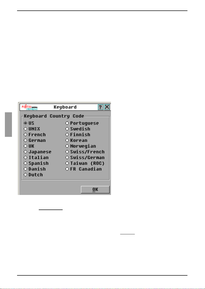
You can use the Keyboard window to send a different keyboard country code than the
default US setting.
Figure 18: Keyboard window
Press Print Screen
Click Setup - Keyboard. The Keyboard window opens.
Select the country code for the keyboard, and click OK. Confirm the change in the
Keyboard Warning window.
Click OK to save the change, or click X or press Escape to exit without saving the
change.
30
to start the OSCAR interface. The Main window opens.
590-591-609B
Page 39

Setting KVM s3-1621 and KVM s3-1641 appliance security
3.9.7 Setting KVM s3-1621 and KVM s3-1641 appliance security
You can enable a s cre en saver to start if the us er rem ain s unused for a spec ifi ed le ngth
of time. When the screen saver starts, the user is disconnected from any target device
to which it was conn ected. The s creen save r stop s wh en yo u p ress any k ey or move the
mouse.
Press Print Screen
If you set a password, the keyboard and mouse are locked when the screen saver
starts.
Press a key or move the mouse while the screen saver is running to open a
Password window opens.
Type the password and click OK to unlock the keyboard and mouse.
If you forget the password, you must call technical support. See section
3.9.7.4 below.
3.9.7.1 Enabling the screen saver
Press Print Screen
Click Setup - Security. If a password is set, the Password window opens. Type the
password and click OK.
Select the Enable Screen Saver check box.
In the Inactivity Time field, type the number of seconds (1 through 99) that must
elapse before the screen save r starts.
If the monitor is Energy Star compliant, select Energy; otherwise, select Screen.
(Optional) To run the screen-saver test, click Test. The screen-saver test runs for
10 seconds.
Click OK.
3.9.7.2 Disabling the screen saver
Press Print Screen
Click Setup - Security. If a password is set, the Password window opens. Type the
password and click OK.
A password must contai n both alp habetic and numeric charac ters and can be up to
12 characters long. Passwords are case-sensitive. Valid characters are A through
Z, a through z, 0 through 9, space, and hyphen.
Clear the Enable Screen Saver check box.
Click OK.
3.9.7.3 Setting or change a password
Press Print Screen
Click Setup - Security. If a password is already set, the Password window opens.
Type the password and click OK.
Double-click the New field.
In the New field, type the new password.
In the Repeat field, type the password again.
Click OK.
and press Pause to immediately start the screen saver.
. The Main window opens.
. The Main window opens.
. The Main window opens.
590-591-609B
31
Page 40

Basic operations
3.9.7.4 Recovering a passw or d
Power cycle the appliance (this will take about 45 seconds)
At the “Fre e” prompt, press Print Screen.
The Authorize window appears.
Click the Forgot Password button at the bottom of the Authorize window.
The following information appears:
• A 16 digit HEX key (example -1234ABCDFFFF7890)
• The EID for the appliance (example - 123456-000001-1234)
• Instructions to contact FSC Customer Support
Keeping the Authorize window open
• Contact FSC Custom er Support to reques t a single us e, emergency p assword.
To obtain the emergency password, you will have to provide the 16 digit HEX
key and the EID for the ap pli anc e. FSC C ust omer Support will return a 1 6 d igi t
HEX emergency password.
• Enter the 16 digit HEX emergency password (case sensitive) in the Authorize
menu.
Utilizing the single use, emergency password will nullify the previous
password.
•Click OK.
The Main window appears, with password security now disabled.
You now have full access to the appliance via the OSCAR menu. You will have to
create a new password to re-enable security if desired.
3.9.7.5 Disabling password protection
Press Print Screen
Click Setup - Security. In the Password window, type the password and click OK.
Double-click the New field. Leave the field blank, and press Enter
Double-click the Repeat field. Leave the field blank, and press Enter.
Click OK.
. The Main window opens.
.
3.10 Setting the preemption warning
Administrators and users with certain access rights can preempt (disconnect) KVM
sessions and take control of the target device. You can choose whether or not to warn
the first user that the sessio n w ill be pre em pted and spec if y ho w lo ng the KVM s 3-16 21
or KVM s3-1641 appliance will wait for the first user to respond to the warning.
For more information a bou t preem pting sess ions and preem ption s etting s, se e the KVM
s3 Client Installation and User’s Guide.
Press Print Screen
Click Setup - Preempt.
Enter a number of seconds in the Timeout Seconds field.
• If you enter a value of 0 to 4 seconds, the first user will not be warned before
the session ispreempted.
32
. The Main window opens.
590-591-609B
Page 41

Managing target device tasks using the OSCAR interface
• If you enter a val ue of 5 to 120 second s, the firs t user w ill be warn ed and wil l be
allowed to continue using the target device for up to the amount of time in the
Timeout Seconds field. The session will be preempted when the user clicks
OK, or when the specified time elapses.
Click OK to save the settings.
Figure 19: Preempt window
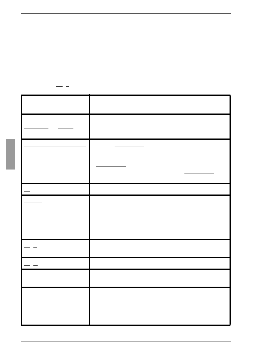
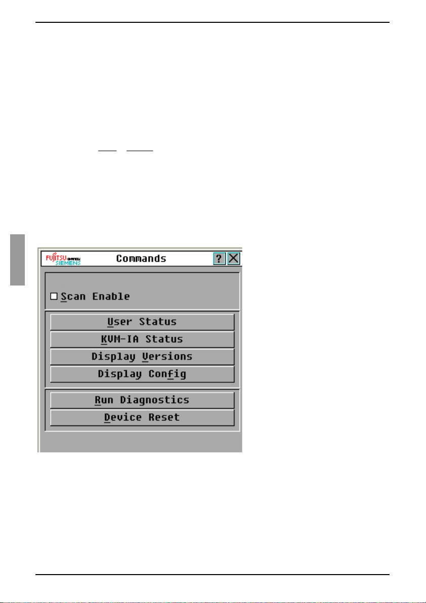
3.11 Managing target device tasks using the OSCAR interface
From the commands window, you can manage the switching system and user
connections, enable Scan mode, and update the firmware.
Feature Purpose
KVM-IA Status View the version and upgrade status of the KVM-IA.
Display config View current display settings.
Run Diagnostics Configure and begin diagnostics on target devices.
Scan Enable Begin scanning the target devices. Set up a target device list
for scanning in the Setup window.
User Status View and disconnect users.
Display V ersi ons View version information for the KVM s3-1621 and
KVM s3-1641 appliances as well as view and upgrade
firmware for individual KVM-IAs.
Device Reset Re-establish operation of the keyboard and mouse.
Table 6: Commands to manage routine tasks for the target device
590-591-609B
33
Page 42

Basic operations
3.11.1 Accessing the Commands window
Press Print Screen. The Main window opens.
Click Commands. The Commands window opens.
Figure 20: Commands window
3.11.2 Displaying version information
You can use the OSCAR interface to view the version of the KVM s3-1621 or KVM s31641 applian c e and the K V M- IA fir mw a re you ar e us ing . For mor e inf orm a tion , see
Appendix 5.1 on page 47.
Press Print Screen
Click Commands - Display Versions. The Version window opens. The top pane of
the window lists the system versio ns in the KVM s 3-1621 or KVM s3-1641 appliance.
34
. The Main window opens.
590-591-609B
Page 43

Upgrading the firmware
Figure 21: Version window
Click the KVM-IA button to view individual KVM-IA version information. The KVM-
IA Select window opens.
Select a KVM-IA to view and clic k the Version button. The KVM-IA Vers ion win dow
opens. For more inform atio n ab out loading firmware, see Appendix 5.1 on page 47.
Click X to close the KVM-IA Version window.
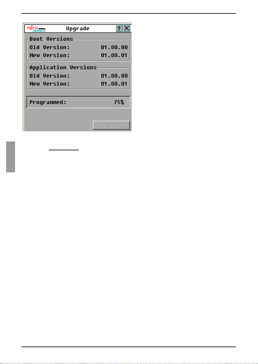
3.11.3 Upgrading the firmware
You can also use the OSCAR interface to upgrade the firmware available for the KVM
s3-1621 and KVM s3-1641 appliances. For optimum performance, keep the firmware
current.
590-591-609B
35
Page 44
Basic operations
Figure 22: Upgrade window
Press Print Screen
Click Commands - Display Versions - Upgrade. The Upgrade window opens.
Click Upgrade. A Warning w indow opens . Clicking OK opens the Upgrade Proc ess
window. The progress of the upgrade is indicated in the Programmed field.
. The Main window opens.
3.1 1.4 V i ewing the display configuration
Use the Display configuration window to view the current configuration of the switching
system.
Click Commands - Display config. The Display configuration window opens and
lists the current sy ste m co nfig ura t ion valu es .
3.1 1.5 V i ewing and disconnecting user connections
You can view and disconnect users from target devices through the User Status
window. The user (U) is always visible; however, you can display either the target
device name or EID number to which a user is connected. If there is no user currently
connected to a channel, the User and Server Name fields are blank.
3.11.5.1 Viewing current user connections
Click Commands - User Status. The User Status window opens.
36
590-591-609B
Page 45

Viewing and disconnecting user connections
Figure 23: User Status window
3.11.5.2 Disconnecting a user
From the User Status window, click the letter that corresponds to the user to
disconnect. The Disconnect window opens.
Complete one of the following steps:
•Click OK to disconnect the user and return to the User Status window.
-or-
• Click X or press Escape
to exit the window without disconne cting a use r.
590-591-609B
If the User Status list has changed since it was last visible, the
mouse cursor will turn into an hourglass as the list is automatically
updated. No mouse or keyboard inp ut is acc ep ted until the lis t
update is complete.
37
Page 46

Basic operations
Figure 24: Disconnect window
3.11 .6 Resetting the keyboard and mouse values
You can reset the keyboard and mouse by clicking Commands - Device Reset. If the
keyboard or mouse is st ill not re spond ing, yo u mi ght be ab le to re-es tabli sh opera tion of
these peripheral switches by issuing a Reset command for the mouse and keyboard
settings on the target server. The Reset command sends a hot-plug sequence to the
KVM-IA, which causes the mouse and keyboard settings to be sent to the earlier
appliance model. With communication re-established between the KVM-IA and the
earlier appliance model, functionality is restored to the user. This function is for
Microsoft Windows-based computers only. Resetting the keyboard and mouse on a
target device running any other operating system might require that you reboot that
target device.
Press Print Screen
Click Commands - Display Versions - KVM-IA. Select the KVM-IA connected to
the mouse and keyboard that need to be reset from the list.
Click Version - Reset.
A message displays stating that the mouse and keyboard are reset.
Complete one of the following steps:
•Click OK to close the message field.
-or-
•Click X or press Escape
mouse and keyboard.
. The Main window opens.
to exit without sending a Reset command to the
38
590-591-609B
Page 47

Scanning the switching system
3.12 Scanning the switching system
In scan mode, the KVM s3-1621 and KVM s3-1641 appliances automatically scan from
port to port (target device to target device). Use scan mode to monitor the activity of up
to 16 target devices, and to specify which target devices to scan and the number of
seconds that each target device will be visible. The scanning order is determined by
placement of the target device in the list, which is always shown in scanning order. You
can choose to list the target devices by name, EID number, or port number by clicking
the corresponding button.
3.12.1 Adding target devices to the scan list
Click Setup - Scan. The Scan window opens.
Figure 25: Scan window
The window contains a listing of all target devices that are attached to the KVM s3-
1621 or KVM s3-1641 appliance. To select target devices to be scanned, complete
one of the following steps:
• Select the check box next to the target dev ices that you w ant to s can.
-or-
• Double-click on a target device n am e or po rt.
-or-
•Press Alt and the EID number of the target device that you want to scan. You
can select up to 16 target devices from the list.
In the Time field, type the number of seconds (from 3 to 255) of time before the
scan moves to the next target devi ce in the seque nc e.
Click OK.
590-591-609B
39
Page 48
Basic operations
3.12.2 Removing a target device from the scan list
To select a target device to be removed from the scan list, complete one of the
following steps:
• In the Scan window, clear the check box next to the target device to be
removed.
-or-
• Double-click on the target device na me or port.
-or-
•Press Shift
it.
-or-
• Click the Clear button to remove all target devices from the scan list.
Click OK.
+ Delete to remove the selected target device and all entries below
3.12.3 Starting the scan mode
Click Commands. The Commands window opens.
Figure 26: Commands window
Select Scan Enable in the Commands window. Scanning will begin immediately.
Click X to close the commands window.
40
590-591-609B
Page 49

Canceling scan mode
3.12.4 Canceling scan mode
• If the OSCAR interface is open, select a target device.
-or-
• If the OSCAR interface is not open, move the mouse or press any key on the
keyboard to stop scanning at the currently selected target device.
3.13 Running switching system diagnostic tests
You can validate the integrity of the switching system through the Run Diagnostics
command. This command checks the appliance functional sub-systems (memory,
communications, earlier appliance model control, and the video channels) for each
system controller.
Figure 27: Diagnostics window
Click Commands - Run Diagnostics. A warning message indicates that all users
(remote and local) will be disconnected.
Click OK
window opens.
The top section of the window opens the hardware tests. The bottom portion
divides the tested KVM-IAs into three c ategori es: On-li ne, Of fline, o r Suspec t. KVM IAs might be listed as offline while being upgraded.
As each test finishes, a pass (green circle) or fail (red x) symbol becomes visible to
the left of the item. The test is complete when the last test symbol is visible.
590-591-609B
to begin diagnostics. All users are disconnected and the Diagnostics
41
Page 50
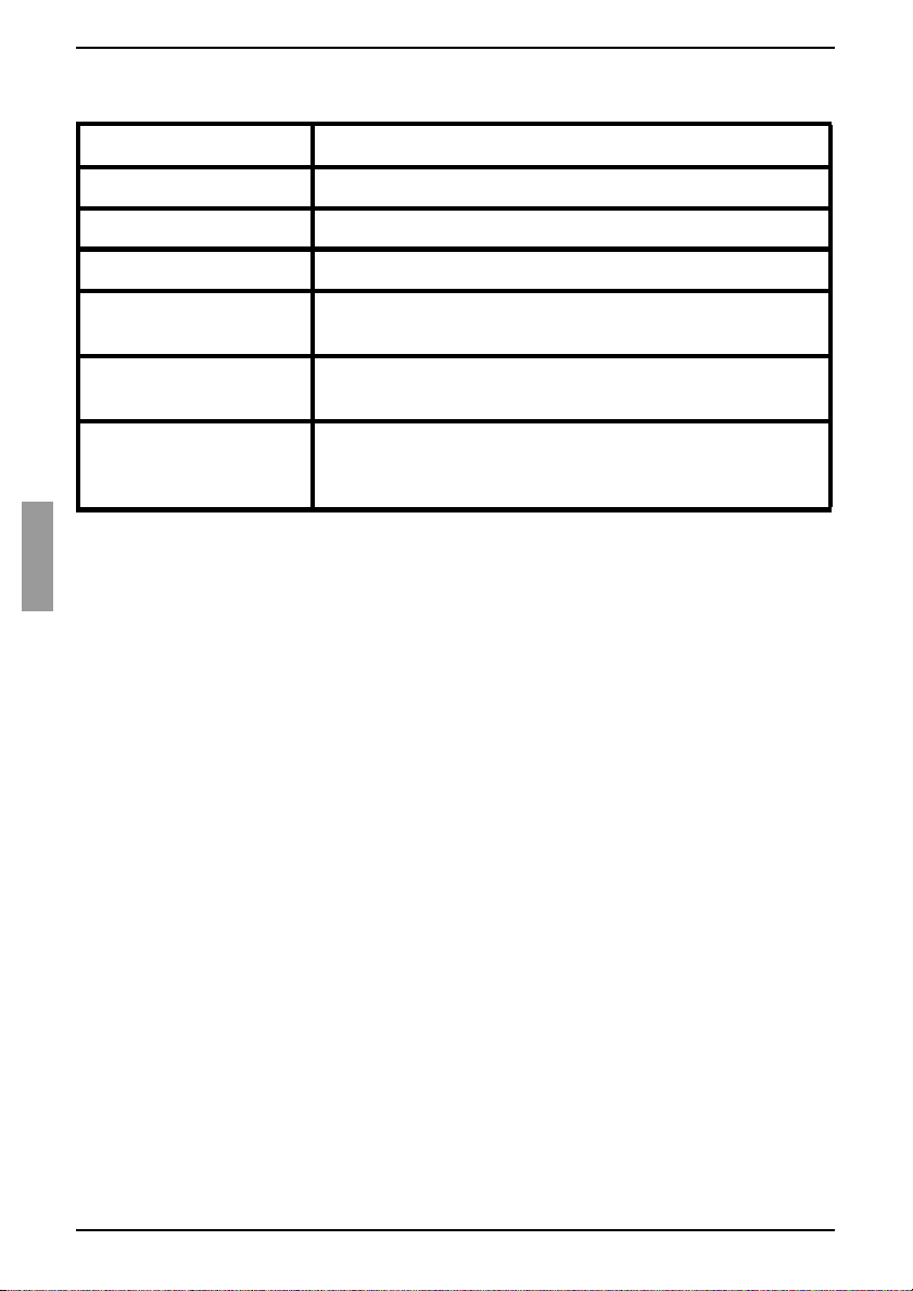
Basic operations
Table 7 details each of the tests.
T est Description
Firmware CRCs Reports on the condition of the appliance RAM.
Remote User Video Reports on the condition of the remote user video.
LAN connection Reports on the condition of the LAN connection.
On-line KVM-IAs Indicates the total number of currently connected and
turned on KVM-IAs.
Offline KVM-IAs Indicates the number of KVM-IAs that have been
connected successfully in the past and are turned off.
Suspect KVM-IAs Indicates the number of KVM-IAs t hat have been detec ted,
but are either unavailable for connection or have dropped
packets during the ping tests.
Table 7: Diagnostic test details
42
590-591-609B
Page 51

4 Computer terminal operations
4.1 The Console menu
Each KVM s3-1621 and KVM s3-1641 appliance can be configured at the appliance
level through the Console menu interface accessed through the configuration port on
the rear panel of the KVM s3-1621 or KVM s3-1641 appliance. All terminal commands
are accessed through a termin al or co mp ute r runni ng term in al em ul atio n sof tw are . This
is not the best method for setting options for the KVM s3-1621 and KVM s3-1641
appliances. The preferred method is to make all configuration settings in the KVM s3
Client. See the KVM s3 Client User Guide for more information.
4.1.1 Configuring network settings
When you turn on the KVM s3-1621 or KVM s3-1641 appliance, the switch initial-
izes for approxima tely o ne mi nute. Af ter it com pletes i nit ializati on, pres s any key on
the terminal or on the computer running the terminal emulation software to access
the Console menu interface. The terminal can be connected at any time, even
when the KVM s3-1621 or KVM s3-1641 appliance is already turned on.
The Console Main menu opens. Type 1 and press Enter
tion option. The Network configuration menu opens.
for the Network configura-
Figure 28: Network configuration menu
Type 1 and press Enter to set the network speed. You should set the connection
manually withou t relyin g on the auto ne gotiate feature. Af ter pressing Enter
returned to the Network configuration menu. See Section 4.1.2 for more details.
Type 2 and press Enter
configuration Protocol (DHCP) address.
590-591-609B
to specify whether you are using a static or Dynamic Host
, you are
43
Page 52

Computer terminal operatio ns
A static IP address can be used to provide a user-define d IP addres s, netmask, and
default gateway for the KVM s3-162 1 and KVM s3-164 1 appl iance s. Use a stat ic IP
address for ease of configuration.
DHCP is a protocol that automates the configuration of TCP/IP-enabled computers.
When DHCP is selected, the IP Address, Netmask, and Default Gateway settings
are automatically assigned to the KVM s3-1621 and KVM s3-1641 appliances and
cannot be modified by a user. If you are using the DHCP option, configure the
DHCP target device to provide an IP address to the KVM s3-1621 or KVM s3-1641
appliance and then skip step 5.
Select the remaining options from the Network configuration menu to finish the
configuration of the KVM s3-1621 or KVM s3-1641 appliance with an IP
address, netmask, default gateway, and ping response.
Type 0 (zero) and press Enter
1621 or KVM s3-1641 appliance will then reboot.
to return to the Console Main menu. The KVM s3-
4.1.2 Configuring network speed settings
When changing network speed and/or network duplex settings on a FSC Digital KVM
switch, the following rules must be considered:
RULE: The settings of the FSC Digital KVM switch and the Network Switch port to
which it is connected must be set to the EXACT same settings.
Examples:
• If the FSC Digital KVM switch is set to Auto-Negotiate, then the Network Switch
MUST be set to Auto-Negotiate both SPEED and DUPLEX.
• If the FSC Digital KVM switch is set to 100MB - FULL duplex, then the Network
Switch must be set to 100MB - FULL duplex.
• If the FSC Digital KVM switch is set to 10MB - HALF duplex, then the Network
Switch must be set to 10MB - HALF duplex.
RULE: If the FSC Digital KVM s witch has b een i n use w ithin th e pas t hour and y ou ha ve
changed the network settings, ARP tables in the network may need refreshing/flushing
before a new connection can be established with the FSC Digital KVM switch.
To refresh the ARP tables, do one of the following:
Wait about 10 minutes or so for the ARP tables to rebuild automatically.
-OR-
Clear the ARP table entry in a FSC Client Viewer workstation and Ping the appli-
ance at its IP address.
commands:
a. ARP -d 1.2.3.4 (Where 1.2.3.4 is the IP address of the FSC Digital
KVM switch.)
b. PING 1.2.3.4 (Where 1.2.3.4 is the IP address of th e FSC D ig ita l KVM s witc h.
If the PING is successful, the FSC Digital KVM switch is ready for operation.)
This can be done from a DOS window with following
44
590-591-609B
Page 53

Other Console Main menu options
4.1.3 Other Console Main menu options
Besides the Network C o nfig ura tio n o pti on, the Console Main m enu of the KVM s3-1621
and KVM s3-1641 appliances have the following menu items: Security Configuration,
Firmware Management, Enable Debug Messages, Restore Factory Defaults, Reset
Device, and Exit. Each is discussed in the following section.
4.1.3.1 Security Configuration
Console Pa ssword: Enable or disable t he console password using security for t he
console (access requires an Admin account).
In the event that you forgot the password, type Help. You will be given a one-time use
key to supply to technical support, who will then supply you with a one-time use
password that you can use to access the Serial Port.
4.1.3.2 Firmware Management
This menu contains the Flash Download selection. For more information, see Appendix
5.1 on page 47.
4.1.3.3 Enable Debug Messages
This menu option turns on console status messages. Because this can significantly
reduce performanc e, you s hould enabl e debu g mess ages only wh en ins tructed to do s o
by technical support. When you are finished viewing the messages, press any key to
exit this mode.
4.1.3.4 Restore Factory Defaults
This menu option will rest ore all KVM s3 -1621 or KVM s3 -1641 appli ance opt ions to the
default settings.
4.1.3.5 Reset the KVM s3-1621 or KVM s3-1641 appliance
You can use this menu option to initiate a soft reset of the KVM s3-1621 or
KVM s3-1641 appliance.
4.1.3.6 Exit
This menu selection will return you to the ready prompt.
590-591-609B
45
Page 54

Computer terminal operatio ns
46
590-591-609B
Page 55

5 Appendices
5.1 Flash upgrades
You can use the KVM s3-1621 and KVM s3-1641 appliance Flash upgrade feature to
update the appliances with the latest firmware available. This update can be performed
using the KVM s3 Client or using a Trivial File Transfer Protocol (TFTP) target server.
After the Flash memory is reprogrammed with the upgrade, the KVM s3-1621 or KVM
s3-1641 appliance pe rforms a soft re set, whic h terminates all KVM-IA se ssions. A target
server experiencing a KVM-IA f irmw are up date migh t not be visi ble or m ight b e listed a s
disconnected. The target server opens normally when the Flash update is completed.
During an upgrade, the KVM-IA status indicator in the OSCAR interface Main window
is yellow.
5.1.1 Upgrading the firmware using the KV M s3 Client
The preferred method for updating the firmware is to use the KVM s3 Client. See the
KVM s3 Client Installation and User’s Guide for detailed instructions. If you do not have
a TFTP server, you can find several shareware and freeware programs on the Internet
that you can download and install.
5.1.2 Upgrading the firmware using the Console menu
Go to http://www.fujitsu-siemens.com/support/ and download the latest Flash firm-
ware. Save the Flash upgrade file to the correct directory on the TFTP target
device.
Use the supplied Null-Modem serial cable to connect a computer running terminal
emulation software to the configuration port on the rear panel of the KVM s3-1621
or KVM s3-1641 appliance.The terminal should be set to 9600 bps, 8 bits, 1 stop
bit, no parity, and no flow control.
If the KVM s3-1621 or KVM s3-1641 appliance is not on, turn it on now. After
approximately one minute, press any key to access the Console Main menu.
After the Console Main me nu opens , selec t the Firmware Ma nagem ent optio n. The
current version of the firmware is opened on the Firmware Management menu.
Type 1 and press Enter
Type the IP address of the TFTP server and press Enter.
Type the name of the Flash file and press Enter.
Confirm the TFTP download by typing a y or yes and pressing Enter
The KVM s3-1621 or KVM s3-1641 appliance will verify that the file you
downloaded is valid .
To confirm the upgrade, type a y or yes and press Enter
The KVM s3-1621 or KVM s3-1641 appliance begins the Flash upgrade process.
On-screen indicators sh ow the upg rade prog res s. Aft er the upl oad is c om pl ete, the
KVM s3-1621 or KVM s3-1641 appliance resets and upgrades the internal
subsystems.
After the upgrade is complete, a verification message is displayed.
to select Flash Download.
.
to confirm.
590-591-609B
47
Page 56

Appendices
5.1.3 Repairing damaged firmware
In the rare case that the firmware is damaged after a firmware upgrade (which might
happen if the KVM s3-1621 or KVM s3-1641 appliance is turned off and turned on
during the upgrade proces s), the KVM s3- 1621 or KVM s3-1 641 applianc e will remain in
boot mode. In this mode, the Power LED on the rear panel flashes at about 1 Hz, and
the KVM s3-1621 or KVM s3-1641 appliance attempts to restore the firmware over
TFTP using the following default configuration:
• TFTP client IP address 10.0.0.2
• TFTP target device IP address 10.0.0.3
• Upgrade the file name to CMN-1016.fl.
To repair damaged firmware:
Connect the KVM s3-1621 or KVM s3-1641 appliance to the TFTP target device
(using a cross-over cable or hub), which is set up with the default IP address
(10.0.0.3).
Rename the upgrade file to the default file name (CMN-1016.fl).
The Power LED will flash at about 2 Hz when the KVM s3-1621 or KVM s3-1641
appliance is downloading the upgrade file, and it will flash at about 4 Hz when it is
programming the downloaded file to Flash. After it has restored the firmware, the KVM
s3-1621 or KVM s3-1641 appliance reboots automatically and the Power LED
illuminates.
5.2 Virtual media
5.2.1 Virtual media and USB 2.0 constraints
The virtual media feature of the KVM s3-1621 and KVM s3-1641 appliances enables
you to connect to the USB port of an attached computer. With this feature, a user
located at a KVM s3-1621 or KVM s3-1641 appliance or using the remote software can
access a local USB storage switch, such as a USB CD drive, diskette drive, or Flash
drive, from an attached compu ter.
The Virtual Media KVM-IA addresses four functions: keyboard, mouse, CD drive, and
mass storage unit. The CD drive and mass storage unit will be present on the target
server whether or not a virtual media session is mapped. If a media device is not
mapped, it is shown without media present. When a virtual media device is mapped to
the target server, the target server will be notified that media has been inserted. When
the media device is unmapped, the target server will be notified that the media was
removed. Therefore, the USB virtual device is not disconnected from the target server.
The KVM-IA presents the keyboard and mouse as a composite USB 2.0 device.
Therefore the BIOS must support composite USB 2.0 human interface device (HID). If
the BIOS of the connected compu t er do es not supp ort thi s ty pe o f dev ice, the key bo ard
and mouse might not work until the operating system loads USB 2.0 device drivers. If
this occurs, there might be a BIOS update provided by the computer manufacturer that
will provide BIOS support for a USB 2.0 connected keyboard and mouse.
48
590-591-609B
Page 57

Booting a computer using virtual memory
5.2.2 Booting a computer using virtual memory
In many cases the virtual media feature can boot an attached computer from a device
attached to the USB port on the KVM s3-1621 or KVM s3-1641 appliance. Most
computers with a USB port can use virtual media; however, limitations in some USB
media devices and the BIOS of some computers might prevent the computer from
booting from a USB device attached to the KVM s3-1621 or KVM s3-1641 appliance.
Booting from a virtual USB device is dependant on the target server supporting booting
from an external composite USB device. It also requires a CD of the operating system
that supports external USB 2.0 booting. The following is a partial list of operating
systems that support booting from an external USB 2.0 device:
• Windows Server 2003
•Windows XP
• Windows 2000 Server with Service Pack 4 (SP4) or later
5.2.2.1 Determining if your computer can be booted from virtual media
Connect a USB CD drive to the KVM s3-1621 or KVM s3-1641 appliance with an
operating system installation CD that is bootable, and map it to the target server.
Reboot the targ et se rve r to determine if it will boot from t his a ttached CD driv e. The
BIOS might need to be set to boot from an external USB device.
If the target server will not boot, connect the USB CD drive to a USB port on the
target server and reboot the target server. If the target server successfully boots
from the CD drive, the BIOS is not supporting booting from a composite USB 2.0
switch. Check the support Web site from the target server manufacturer to
determine if a later BIOS is available that might support booting from a composite
USB 2.0 device. If so, update the BIOS and retry.
If the target server is not capable of booting from an external USB 2.0 device, try
the following methods to remotely boot this target server:
• Some BIOS versions provide an option to limit USB speeds. If this option is
available to you, change the USB port setting to “USB 1.1” or “Full Speed”
mode, and try booting agai n.
-or-
• Insert a USB 1.1 card, and try booting again.
-or-
• Insert a USB 1.1 Hub between the KVM-IA and the target server, and try
booting again.
-or-
• Contact the manufacturer of the target server for information on availability or
plans of a BIOS revision that will support booting from a composite USB 2.0
device.
590-591-609B
49
Page 58

Appendices
5.2.2.2 Virtual media restricti ons
The following list specifies restrictions for using virtual media:
• The KVM s3-1621 and KVM s3-1641 virtual media appliances support only the
connection of USB 2.0 diskette drives, Flash drives, and CD drives.
• The KVM s3 Client supports only mapping of USB 2.0 and USB 1.1 diskette drives
and Flash drives connected to the client computer.
5.3 UTP cabling
The following information is intended to brief you on various aspects of connection
media. The performance of a switching system depends on high quality connections.
Poor quality or poorly installed or maintained cabling can diminish system
performance.This append ix is for in formati on purp oses onl y. Consul t with th e loca l cod e
officials or cabling consultants prior to any installation.
5.3.1 UTP copper cabling
Switching systems use unshielded twisted pair (UTP) cabling.The following are basic
definitions for the three types of UTP cabling that the KVM s3-1621 and KVM s3-1641
appliances support:
• Cat 5 UTP (4-pair) high performance cable consists of twisted pair conductors,
used primarily for dat a tran smissi on. The tw isti ng of the p airs gives this ca ble som e
immunity from the infiltration of unwanted interference. Cat 5 cable is generally
used for networks running at 100 or 1000 Mbps.
• Cat 5E (enhanced) cable has the same characteristics as Cat 5, but is
manufactured to somewhat more stringent standards.
• Cat 6 cable is manufactured to tighter requirements than Cat 5E cable. Cat 6 has
higher measured frequency ranges and significantly better performance
requirements than Cat 5E cable at the same frequencies.
50
590-591-609B
Page 59

Wiring standards
5.3.2 Wiring standards
There are two supported wiring standards for 8-conductor (4-pair) RJ-45 terminated
UTP cable: EIA/TIA 568A and B. These standards apply to installations utilizing Cat 5,
5E, and 6 cable specifications. The switching system supports either of these wiring
standards. Refer to the following table for details.
Pin EIA/TIA 568A EIA/TIA 568B
1 white/green white/orange
2 green orange
3 white/orange white/green
4blue blue
5 white/blue white/blue
6 orange green
7 white/brown white/brown
8brown brown
Table 1: UTP wiring standards
5.3.3 Cabling installation, maintenance, and safety tips
The following is a l ist o f i mp ortan t saf ety c ons id era tion s that should be revi ew ed p rior to
installing or maintaining the cables:
• Keep all Cat 5 runs to a max i mum of 10 meters each.
• Maintain the twists of the pairs all the way to the point of termination, or no more
that one-half inch untwisted. Do not skin off more than one inch of jacket while
terminating.
• If bending the cable is necessary, make it gradual with no bend sh arpe r than a oneinch radius. Sharply bending or kinking the cable can permanently damage the
interior of the cable.
• Arrange the cables neatly with cable ties, using low to moderate pressure. Do not
over tighten ties.
• Cross-connect cables where necessary, using rated punch blocks, patch panels,
and components. Do not splice or bridge cables at any point.
• Keep the Cat 5 cable as far away as possible from potential sources of EMI, such
as electrical cables, transformers, and light fixtures. Do not tie cables to electrical
conduits or lay cables on electrical fixtures.
• Always test every installed segment with a cable tester. Toning alone is not an
acceptable test.
590-591-609B
51
Page 60

Appendices
• Always install jacks to prevent dust and other contaminants from settling on the
contacts. The contacts of the jack should face up on the flush mounted plates, or
left, right, or down on surface mount boxes.
• Always leave extra slack in the cables, neatly coiled in the ceiling or nearest
concealed locatio n. Leave at le ast fi ve fee t at th e work ou tlet s ide an d 10 feet at the
patch panel side.
• Choose either 568A or 568B wiring standard before beginning. Wire all jacks and
patch panels for the same wiring scheme. Do not mix 568A and 568B wiring in the
same installation.
• Always follow all local and national fire and building codes. Be sure to firestop all
cables that penetrate a firewall. Use plenum rated cable where it is required.
5.4 Technical spe cifications
Target Server Ports
Number 16
Types ARI
Connectors RJ-45
Sync Types Separate horizontal and vertical
Plug and Play DDC2B
Video Resolution 640 x 480 @ 60 Hz (Local Port and Remote Port Minimum)
800 x 600 @ 75 Hz
960 x 700 @ 75 Hz
1024 x 768 @ 75 Hz
1280 x 1024 @ 75 Hz (Remote Port Maximum using a
KVM-IA)
Supported Cabling 4-pair UTP Cat 5 or Cat 6, 10 meters maximum length
Serial Port
Number 1
Cable type Serial RS-232
Connector DB9 female
Network Connection
Number 1
Type Ethernet: IEEE 802.3 2002 Edition - 10BASE-T, 100BASE-
T1000BASE-T
Connector RJ-45
Table 2: KVM s3-1621 and KVM s3-1641 appliance product specifications
52
590-591-609B
Page 61

Technical specifications
Local Port
Number 1
Type USB, PS/2, and VGA
Connectors PS/2 miniDIN, 15 pin D, RJ-45
USB Switch Port
Number 4
Type USB 2.0
Dimensions
Height x Width x Depth 1.72 in. x 17.00 in.x 10.98; 1-U form factor
(4.37 cm x 43.18 cm x 27.98)
Weight 7.3 lbs (3.31 kg) without cables
Power Supply
Heat dissipation 92 BTU/Hr
Airflow 8 CFM
Power consumption 12.5 Watts
AC-input power 40 Watts maximum
AC-input voltage rate 100 to 240 V ac Auto-sensing
AC-input current rating 0.5 A
AC-input cable
18 AWG three-wire cable, with a three-lead
receptacle on the power supply end and a country-
C14
dependent connector on the power resource end
AC frequency 5 0 to 60 Hz auto-sensing
Ambient Atmospheric Condition Ratings
Temperature
o
0
to 50o Celsius (32o to 122o Farenheit) operating
o
-20
to 60o Celsius (-4o to 140o Farenheit) nonoperating
Humidity 20 to 80% noncondensing operating
5 to 95% noncondensing nonoperating
Safety and EMC Approvals and Markings
UL, FCC, cUL, ICES, CE, N, GS, IRAM, GOST, VCCI, MIC, C-Tick
Table 2: KVM s3-1621 and KVM s3-1641 appliance product specifications
590-591-609B
EN 60320
53
Page 62

Appendices
5.5 Technical Support
Our Technical Support staff is ready to assist you with any installation or operating
issues you encounter with your Fujitsu Siemens product. If an issue should develop,
follow the steps below for the fastest possible service: Check the pertinent section of
this manual to see if the issue can be resolved by following the procedures outlined.
Check our web site at http://www.fujitsu-siemens.com/support/ and click on Services &
Support. Click helpdesk on the left side of the page for a listing of technical support
phone numbers in your area.
5.5.1 Before you call
Before you call, make sure that you have taken these steps to try to solve the
problem yourself:
• Check all cables to make sure that they are connected.
• Check the power switches to make sure that the system and any optional devices
are turned on.
• Use the troubleshooting information in your system documentation, and use the
diagnostic tools that come with your system.
• Go to the Fujitsu Siemens support Web site at http://www.fujitsu-siemens.com/
support/ to check for technical information, hints, tips, and new device drivers or to
submit a request for information.
You can solve many problems without outside assistance by following the
troubleshooting procedures that Fujitsu Siemens provides in the online help or in the
documentation that is provided with your Fujitsu Siemens product. If you suspect a
software problem, see the documentation for the operating system or program.
54
590-591-609B
Page 63

KVM s3-1621 und s3-1641
Bedienungsanleitung
Ausgabe Juli 2007
Page 64

Kommentare… Vorschläge… Verbesserungen
Unsere Abteilung für technische Dokumentation würde gerne Ihre Meinung zu diesem
Handbuch erfahren. I hr Feedb ack hilf t uns, unsere Dokum entation z u optimie ren, indem
Ihre individuellen Anforderungen erfüllt werden. Sie finden hinten im Handbuch FaxFormulare, mit denen Sie uns Ihre Kommentare zuschicken können. Dort befindet sich
auch die Adresse der entsprechenden Abteilung für technische Dokumentation.
Zertifizierte Dokumentation
gemäß DIN EN ISO 9001:2000
Zur Sicherstellung vo n k ons istent hohen Qualitäts sta nda rds und Ben utz erfre undlichkeit
wurde diese Dokumentation in Übereinstimmung mit den Vorschriften eines
Qualitätssicherungssystems erstellt, das den Anforderungen der Norm DIN EN ISO
9001:2000 entspricht.
Copyright und Marken
Copyright © 2006 Fujitsu Siemens Computers GmbH.
Alle Rechte vorbehalten.
Liefermöglichkeiten und technische Änderungen vorbehalten.
Alle verwendeten Hardware- und Softwarebezeichnungen sind Marken der
entsprechenden Hersteller.
Diese Bedienungsanleitung ist
auf chlorfrei gebleichtem
Papier gedruckt.
Page 65

Inhalt
Inhalt
1 Produktüberblick.....................................................................................1
1.1 Glossar......................................................................................................1
1.2 Darstellungskonventionen.........................................................................1
1.3 Merkmale und Vorteile ................................... ...........................................2
1.3.1 KVM-IA - Intelligente Adapter........................................................... ...... ...3
1.3.2 Virtual Media .............................................................................................4
1.3.3 Grafische Benutzeroberfläche OSCAR.....................................................4
1.3.3.1 Sicherheit ..................................................................................................4
1.3.3.2 Betriebsmodi .............................................................................................5
1.3.4 Video.........................................................................................................5
1.3.5 Flash-Aktualisierungen..............................................................................5
1.3.6 Zugriff auf die Einheiten über eine Netzwerkverbindung ..........................5
1.3.7 Zugriff auf Zielgeräte.................................................................................5
1.3.8 Integrierte Weboberfläche.........................................................................5
2 Installation ...............................................................................................7
2.1 Überblick über die Installation...................................................................7
2.1.1 Installation der KVM s3-1621- oder KVM s3-1641-Einheit........................7
2.1.2 Einrichten des Netzwerks..........................................................................8
2.2 Erforderliche Komponenten.......................................................................9
2.3 Sicherheitsvorkehrungen...........................................................................9
2.3.1 Allgemeine Sicherheitshinweise................................................................9
2.4 Rackbefestigung einer KVM-Einhei t..................... ...... ..... ...... ..................11
2.4.1 Allgemeine Anweisungen........................................................................11
2.4.2 Installation einer KVM-Einheit durch Rackbefestigung............................11
2.5 Anschließen der KVM-Einheiten-Hardware.............................................12
2.5.1 Anschließen eines KVM-IA an ein Zielgerät............................................13
2.5.2 Anschließen von lokalen Peripheriegeräten............................................13
2.6 Überprüfen der Ethernet-Verbindungen..................................................13
2.7 Konfigurieren des KVM s3 Client.............................................................13
2.8 Anpassen der Mauseinstellungen...........................................................14
2.9 Anschließen von älteren Einheitenmodellen an eine KVM s3-1621-
oder KVM s3-1641-Einheit14
2.9.1 Anschließen eines nicht kompatiblen Switch-Modells.............................15
2.10 Einrichten der KVM s3-1621- und KVM s3-1641-Einheiten ....................16
3 Normalbetrieb........................................................................................17
3.1 Steuern des Switching-Systems über den Analogport............................17
3.2 Aufrufen der OSCAR-Benutzeroberfläche...............................................17
3.3 Einstellen der Zeitverzögerung................................................................19
590-591-609B
Page 66

Inhalt
3.4 Verbinden eines Benutzers mit einem Zielgerät......................................19
3.5 Auswählen des vorherigen Zielgeräts.....................................................20
3.6 Trennen der Verbindung zwischen Benutzer und Zielgerät....................20
3.7 Verwenden der OSCAR-Benutzerobe rflä che..........................................20
3.8 Anschließen von lokalem Virtual Media...................................................22
3.9 Konfigurieren der Einheiten und der OSCAR-Benutzeroberfläche..........23
3.9.1 Zuweisen von Zielgerätenamen..............................................................24
3.9.2 Zuweisen von Einheiten- und Gerätetypen.............................................26
3.9.2.1 Zugriff auf das Dialogfeld „Geräte“..........................................................27
3.9.2.2 Zuweisen des Switch-Typs......................................................................27
3.9.3 Ändern des Anzeigeverhaltens ...............................................................28
3.9.3.1 Auswählen der Anzeigereihenfolge für Zielgeräte...................................29
3.9.3.2 Auswählen der Tastenkombinationen.....................................................29
3.9.3.3 Einstellen der Zeitverzögerung................................................................29
3.9.4 Auswählen der Anzeigensprache............................................................30
3.9.5 Steuern des Status-Flags .......................................................................30
3.9.6 Einstellen der länderspezi fis ch en Tas tatu r............................ ...... ..... ...... .32
3.9.7 Einstellen der Sicherheit für die KVM s3-1621-
und KVM s3-1641-Einheiten ...................................................................33
3.9.7.1 Aktivieren des Bildschirmschoners.............................................. ..... ...... .34
3.9.7.2 Deaktivieren des Bildschirmschoners......................................................34
3.9.7.3 Einrichten oder Ändern des Kennworts...................................................34
3.9.7.4 Wiedererlangen des Kennworts..............................................................34
3.9.7.5 Deaktivieren des Kennwortschutzes.......................................................35
3.10 Einrichten der Unterbrechungswarnung..................................................35
3.11 Verwalten der Aufgaben der Zielgeräte über die
OSCAR-Benutzerober-fläche..................................................................36
3.11.1 Zugriff auf das Dialogfeld „Befehle“.........................................................37
3.11.2 Anzeigen der Versionsinformationen.......................................................37
3.11.3 Aktualisieren der Firmware......................................................................38
3.11.4 Anzeigen der Anzeigekonfiguration.........................................................39
3.11.5 Anzeigen und Trennen von Benutzerverbindungen................................39
3.11.5.1 Anzeigen der aktuellen Benutzerverbindungen.......................................39
3.11.5.2 Trennen von Benutzerverbindungen.......................................................40
3.11.6 Zurücksetzen der Tastatur- und Mauswerte............................................41
3.12 Scannen des Switching-Systems............................................................42
3.12.1 Hinzufügen von Zielgeräten zur Scan-Liste..................... ........................42
3.12.2 Entfernen eines Zielgeräts aus der Scan-Li ste ..... .................................. .43
3.12.3 Starten des Scan-Modus.........................................................................43
3.12.4 Abbrechen des Scan-Modus...................................................................44
590-591-609B
Page 67

Inhalt
3.13 Diagnosetest des Switching-Systems.....................................................44
4 Terminalbetrieb des Computers...... ....................................................47
4.1 Konsolenmenü ........................................................................................47
4.1.1 Konfigurieren der Netzwerkeinstellungen................................................47
4.1.2 Konfigurieren der Netzwerkgeschwindigkeit............................................48
4.1.3 Weitere Optionen im Konsolenhauptmenü..............................................49
4.1.3.1 Security Configuration (Sicherheitskonfiguration) ...................................49
4.1.3.2 Firmware Management............................................................................49
4.1.3.3 Enable Debug Messages (Debug-Nachrichten aktivieren)......................49
4.1.3.4 Restore Factory Defaults (Standardeinstellungen wiederherstellen)......49
4.1.3.5 Zurücksetzen der KVM s3-1621- oder KVM s3-1641-Einheit..................49
4.1.3.6 Exit (Beenden)........................................... ..... ........................................ .49
5.1 Flash-Aktualisierung................................................................................51
5.1.1 Firmware-Aktualisierung über den KVM s3 Client...................................51
5.1.2 Firmware-Aktualisierung über das Konsolenmenü..................................51
5.1.3 Reparieren von beschädigter Firmware..................................................52
5.2 Virtual Media ...........................................................................................52
5.2.1 Einschränkungen von Virtual Media und USB 2.0...................................52
5.2.2 Starten des Computers mithilfe eines virtuellen Speichers.....................53
5.2.2.1 Feststellen, ob der Computer über Virtual Media
gestartet werden kann.............................................................................53
5.2.2.2 Einschränkungen für Virtual Media..........................................................54
5.3 UTP-Kabel...............................................................................................54
5.3.1 UTP-Kupferkabel.....................................................................................54
5.3.2 Kabelnormen...........................................................................................55
5.3.3 Kabelinstallation, Kabelwartung und Sicherheitshinweise.......................55
5.4 Technische Daten ...................................................................................56
5.5 Technischer Kundendienst......................................... ..... ...... ...... ............58
5.5.1 Vor dem Anruf.........................................................................................58
590-591-609B
Page 68

Inhalt
590-591-609B
Page 69

1 Produktüberblick
Die KVM s3-1621- und KVM s3-1641-Einheiten kombinieren digitale und analoge KVMSwitching-Technologie (Keyboard, Video, Maus) mit ausgereiftem Kabelmanagement,
Zugriff für zwei bis vier Benutzer gleichzeitig und einer intuitiven Benutzeroberfläche.
Die Einheiten verfügen an der Rückseite des Geräts über USB- und PS/2
die alle gängigen Zielgeräte-Plattformen unterstützen.
1.1 Glossar
In diesem Handbuch werden folgende Begriffe verwendet:
• ACI-Port: ACI steht für „Analog Con sole I nterfac e“. Dies i st ein Port an b estim mten
Fujitsu Siemens KVM-Switches, der als integrierter KVM-IA-Adapter zu
Stufungszwecken verwendet wird.
• ARI-Port: ARI steht für „Analog Rack Interface“. Über den ARI-Port werden
Computer und KVM-Switches mithilfe eines KVM-IA-Adapters an KVM series2und KVM series3-Switches angeschlossen.
• KVM s3-1621 und KVM s3-1641: Einheiten, die KVM-over-IP-Konnektivität mit den
angeschlossenen Zielgeräten ermöglichen. Die Bezeichnung Einheit bezieht sich
in diesem Handbuch auf einen KVM-Switch, der vom KVM s3-Client verwaltet wird.
• KVM-IA (Keyboard/Video/Maus-Interface Adapter): Dieser Adapter bietet
zusätzliche Funktionen, z. B. Virtual Media-Sitzungen, wenn er an die Einheit und
ein Zielgerät angeschlossen ist.
• Switching-System: Eine Gruppe von Einheiten, angeschlossenen Zielgeräten
und KVM-IAs.
• Zielgerät: Ein Gerät, das über einen KVM-IA an eine Einheit angeschlossen ist,
beispielsweise ein Server oder Router.
• Lokaler Benutzer: Benutzer mit Zugriff auf Tastatur, Bildschirm und Maus, die
direkt mit der Einheit verbunden sind. Dieser Benutzer hat uneingeschränkten
Zugriff auf alle Zielgeräte.
• Remote-Benutzer: Ein Benutzerkonto in der Benutzerdatenbank der lokalen
Einheit oder auf einem zentralen Active Directory-Server. Dieses Benutzerkonto
ermöglicht den Managementzugriff auf die Einheit und die angeschlossenen Geräte.
• Virtual Media: Ein USB-Mediengerät, das an die KVM s3-1621- und
KVM s3-1641-Einheiten angeschlossen werden kann und das Zielgeräten, die mit
einer KVM s3-1621- oder KVM s3-1641-Einheit verbunden sind, zur Verfügung
gestellt werden kann.
®
-Ports,
1.2 Darstellungskonventionen
In diesem Handbuch werden die folgenden Darstellungskonventionen verwendet:
Fett Hebt wichtigen Text hervor.
Taste
Kursiv Hebt Befehle, Dateinamen, Menübezeichnungen und
590-591-609B
Hebt Tasten oder Tastenkombination im Fließtext hervor.
Eingaben im Fließtext hervor.
1
Page 70

Produktüberblick
l
Verweist auf zusätzliche Informationen und Tipps.
Tite
Verweist auf einen Schritt, den Sie ausführen müssen.
- und • Diese Zeichen weisen auf Gliederungen hin.
Bold monospace font Gibt Eingaben des Benutzers in Beispielen an.
Verweist auf Informationen, die bei Nichtbeachtung Ihre
Gesundheit, die Funktionsfähigkeit des Systems oder die
Datensicherheit beeinträchtigen können.
1.3 Merkmale und Vorteile
Die KVM s3-1621- und KVM s3-1641-Einheiten sind rackmontierbare KVM-Switches,
die für analoge (lokale) oder digitale (Remote-) Konnektivität konfiguriert werden
können. Für Remote-Benutzer werden Bildschirmauflösungen bis 1280 x 1024
unterstützt.
Die KVM s3-1621-Einheit umfasst zwei digitale Port-Sets für KVM-over-IP-Zugriff,
ein analoges Port-Set für KVM-Zugriff, 16 ARI-Ports zum Anschluss von KVM-IAs und
Zielgeräten und Virtual Media-Funktionalität für einen lokalen und bis zu zwei RemoteBenutzer.
Die KVM s3-1641-Einheit umfasst vier digitale Ports für KVM-over-IP-Zugriff, ein
analoges Port-Set für KVM-Zugriff, 16 ARI-Ports zum Anschluss von KVM-IAs und
Zielgeräten und Virtual Media-Funktionalität für einen lokalen und bis zu vier RemoteBenutzer.
Beide Einheiten können mit der KVM s3 Client-Anwendung verwendet werden,
um diese Einheiten sowie die Legacy KVM series2-Einheit (KVM2-1611) und die
angeschlossenen Zielgeräte anzuzeigen und zu steuern. Weitere Informationen zum
KVM s3 Client finden Sie im Benutzerhandbuch „Verwalten von KVM-Einheiten“.
Abbildung 1: KVM s3-1621-Einheit
2
590-591-609B
Page 71

KVM-IA - Intelligente Adapter
Abbildung 2: KVM s3-1641-Einheit
Die KVM s3-1621- und KVM s3-1641-Einheiten verfügen über Benutzer-Peripherie-
Ports für PS/2®- und USB-Tastaturen und -Mäuse. Darüber hinaus können Virtual
Media-Geräte wie z. B. generische Wechseldatenträger und CD-Laufwerke an jeden
der vier USB-Ports angeschlossen werden.
Die KVM s3-1621- und KVM s3-1641-Einheiten arbeiten über standardmäßige LANVerbindungen. Benutzer können mithilfe eines 1000BASE-T-LAN-Ports über eine
Ethernet-Verbindung oder direkt über einen lokalen Port auf Zielgeräte zugreifen.
Mithilfe der IP-basierten KVM s3-1621- und KVM s3-1641-Einheiten können Sie
Zielgeräte von jedem Standort weltweit aus steuern.
1.3.1 KVM-IA - Intelligente Adapter
Sie können die folgenden KVM-IAs in Verbindung mit den KVM s3-1621- und KVM s31641-Einheiten verwend en:
• KVM S2-Adapter PS/2-VGA - PS/2- und VGA-Stecker
• KVM s2-Adapter SUN-VGA - PS/2- und VGA-Stecker
• KVM s3-Adapter USB2-VGA - USB2- und VGA-Stecker, für Virtual MediaVerbindungen erforderlich
• KVM s2-Adapter 1.1 USB-VGA - USB- und VGA-Stecker
PS/2- und VGA-Stecker KVM s3-Adapter USB2-VGA
Abbildung 3: Beispiele für KVM-IAs
Diese intelligenten KVM-IAs im CAT 5-Design reduzieren den Kabelaufwand
entscheidend und bieten gleichzeitig optimale digitale Bildschirmauflösungen und
Videoeinstellungen. Der integrierte Speicher des KVM-IA vereinfacht die Konfiguration,
indem jedem angeschlossenen Zielgerät eindeutige Identifikationscodes zugewiesen
590-591-609B
3
Page 72

Produktüberblick
und dauerhaft gespeichert werden. Diese integrierte „Intelligenz“ verbessert die
Sicherheit und verhindert einen unautorisierten Zugriff auf ein Zielgerät durch
Kabelmanipulation. Der KVM-IA wird direkt vom Zielgerät mit Strom versorgt und
verfügt selbst bei ausgeschalteter KVM s3-1621- oder KVM s3-1641-Einheit über
eine „Keep Alive“-Funktionalität.
Die KVM-IAs ermöglichen direkte KVM-Konnektivität mit Zielgeräten, die an die KVM
s3-1621- oder KVM s3-1641-Einheit angeschlossen sind. Jede KVM s3-1621- und
KVM s3-1641-Einheit verfügt über 16 ARI-Ports für den Anschluss von KVM-IAs.
Die KVM-IAs, di e in Ve rbin du ng mit den Ei nh eite n ve r wend et w erde n, unt e rs tütz en
Zielgeräte mit P S/2- un d U SB- P ort s so wi e 8-polige SUN-Ports für Tastatur und Maus.
Bei Verwendung der OSCAR-Be nutzeroberfläche in V er bin dun g mi t K VM -IA s is t d er
problemlose Wechsel zwischen Pl attformen möglich.
1.3.2 Virtual Media
Die KVM s3-1621- und KVM s3-1641-Einheiten unterstützen Virtual Media, wenn sie
an einen KVM-IA angeschlossen sind. Mit dieser Virtual Media-Unterstützung können
USB-Geräte an eine KVM s3-1621- oder KVM s3-1641-Einheit angeschlossen werden
und werden so für alle angeschlossenen Einheiten verfügbar.
Virtual Media eignet sich zum Austauschen von Daten zwischen Zielgeräten und USBMediengeräten, die mit der KVM s3-1621- oder KVM s3-1641-Einheit verbunden sind.
Mithilfe der Virtual Media-Funk tio nal ität der KVM s3-1621- und KVM s3-1641-Einhei ten
können Sie auch das Betriebssystem installieren, aktualisieren oder wiederherstellen,
den BIOS-Code aktualisieren und das Zielgerät über ein USB-Laufwerk starten.
Virtual Media-Geräte kö nnen über ei nen de r vie r USB-Ports dire kt an die KVM s 3-1621 und KVM s3-1641-Einheiten angeschlossen werden. Darüber hinaus können Virtual
Media-Geräte an jede Remote-Workstation angeschlossen werden, auf welcher der
KVM s3 Client ausgeführt wird, wenn sie über eine Ethernet-Verbindung mit der
Einheit verbunden ist. Um eine Virtual Media-Sitzung mit einem Zielgerät zu öffnen,
muss das Zielgerät zuerst mit einem KVM s3-Adapter USB2-VGA-Kabel an die Einheit
angeschlossen werden. Weitere Informationen zur integrierten Weboberfläche finden
Sie in der Virtual Media Bedienungsanleitung.
1.3.3 Grafische Benutzeroberfläche OSCAR
Die KVM s3-1621- und KVM s3-1641-Einheiten verwenden die grafische
Benutzeroberfläche OSCAR
Benutzeroberfläche können Sie das Switching-System konfigurieren und Computer
auswählen. Zielgeräte können nach eindeutigen Namen, EID (elektronischen
Kennnummern) oder nach Portnummern aufgelistet werden.
1.3.3.1 Sicherheit
Verwenden Sie die OSCAR-Benutzeroberfläche, um das Switching-System mit einem
Bildschirmschoner-Kennwort zu schützen. Nach einem benutzerdefinierten Zeitintervall
wird der Bildschirmschonermodus aktiviert und es ist kein Zugriff möglich, bis das
entsprechende Kennwort zur Reaktivierung des Switching-Systems eingegeben wird.
4
®
für Fujitsu-Siemens Computers. Mit den Menüs dieser
590-591-609B
Page 73

Video
1.3.3.2 Betriebsmodi
Die OSCAR-Benutzeroberfläche bietet verschiedene Betriebsmodi für die
Systemadministration der KVM s3-1621 und KVM s3-1641-Einheiten. Mithilfe dieser
Modi (Scannen, Switching und Teilen) können Sie die Switching-Aktivitäten verwalten.
Weitere Informationen finden Sie im auf Seite 17 beginnenden Kapitel
3„Normalbetrieb“.
1.3.4 Video
Die KVM s3-1621- und KVM s3-1641-Einheiten ermöglichen optimale
Bildschirmauflösungen für analoges VGA-, SVGA- und XGA-Video. Je nach
Kabelabstand zwischen der KVM s3-1621- oder KVM s3-1641-Einheit und den
Zielgeräten lassen sich Auflösungen bis 1280 x 1024 erzielen.
1.3.5 Flash-Aktualisierungen
Die KVM s3-1621- und KVM s3-1 641-Einheiten k önnen jederzeit über den Netzwe rkport
aktualisie rt werden, um sicherzustellen, dass sie stets unter der aktuell erhältlichen
Version betrieben werden. Zusätzliche Informationen finden Sie im Anhang 5.1 auf
Seite 51.
1.3.6 Zugriff auf die Einheiten über eine
Netzwerkverbindung
Benutzer können von einem Client-Computer über Ethernet auf die KVM s3-1621und KVM s3-1641-Einheiten und alle angeschlossenen Zielgeräte zugreifen. Ein ClientComputer kann sich an jedem Standort mit geeigneter Netzwerkverbindung befinden.
1.3.7 Zugriff auf Zielgeräte
Wenn Sie auf den KVM s3 Client zugreifen, werden alle Zielgeräte, für die Sie Zugriffsund Verwaltungsrechte haben, aufgelistet. Wenn Sie ein Zielgerät in der Liste
auswählen, wird der Bildschirm des ausgewählten Zielgeräts in einem Video ViewerFenster angezeigt.
1.3.8 Integrierte Weboberfläche
Die integrierte Weboberfläche bietet ähnliche Verwaltungsfunktionen wie der KVM
s3 Client, es ist jedoch kein Software-Server und keine Installation erforderlich. Die
integrierte Weboberfläche wird direkt von der Einheit gestartet und alle an die
KVM s3-1621- und KVM s3-1641-Einheiten angeschlossenen Server werden
automatisch erkannt. Mit der integrierten Weboberfläche können Sie KVM s3-1621und KVM s3-1641-Einheiten über einen Webbrowser konfigurieren. Rufen Sie den
Viewer über die integrierte Webob erfläche auf, um ei ne KVM- und Virtual Media-Sitzu ng
mit den Zielger äten e inz uri ch ten. We ite r e Info rma tio nen zur integrierten W ebo berf läc he
finden Sie im Benutzerhandbuch „Verwalten von KVM-Einheiten“.
590-591-609B
5
Page 74

Produktüberblick
r
Abbildung 4 zeigt eine typische KVM s3-1621- oder KVM s3-1641Einheitenkonfiguration .
Rack mit
Zielservern
KVM s3-1621- oder KVM s3-1641-Einheit
Ethernet
Digitaler Benutze
Analoger Benutzer
Digitaler Benutzer
Abbildung 4: Beispielkonfiguration einer KVM s3-1621- oder KVM s3-1641-Einheit
Lokale
KVM-
Einheitenmodelle
s3-1621 16 2 1 1 2
s3-1641 16 4 1 1 4
Anzahl der
ARI-Ports
Digitale
Pfade
Analoger
Benutzer
Virtual
Media-
Sitzungen
Remote-
VirtualMedia-
Sitzungen
Abbildung 5: Vergleich der KVM s3-1621- und KVM s3-1641-Einheitenmodelle
6
590-591-609B
Page 75

2Installation
Die KVM s3-1621- und KVM s3-1641-Einheiten müssen mit einem Computer
verbunden sein, auf dem der KVM s3 Client ausgeführt wird. Mit dem KVM s3 Client
können Sie Zielgeräte, die an eine KVM s3-1621- oder KVM s3-1641-Einheit
angeschlossen sind, anzeigen und steuern (ein Gerät nach dem anderen). Der KVM
s3 Client ist für den Betrieb des Analogports nicht not wendig. Der Analogp ort verwende t
OSCAR als grafische Benutzerob erfl äc he von Fujit su Siem en s. Wei tere Informationen
finden Sie in Kapitel 3, „Normalbetrieb“, beginnt auf Seite 17 oder in der KVM s3 Client
Bedienungsanleitung.
Die KVM s3-1621- und KVM s3-1641-Einheiten übertragen KVM-Informationen über
eine Ethernet- oder lokale Netzwerkverbindung zwischen Benutzern und Zielgeräten,
die mit einer anderen Einheit verbunden sind.
Die KVM s3-1621- und KVM s3-1641-Einheiten verwenden TCP/IP für die
Kommunikation über Ethernet. Es kann zwar ein 10BASE-T-Ethernet verwendet
werden, ein eigenständiges geswitchtes 100BASE-T-Netzwerk oder ein 1000BASET-Netzwerk erhöht jedoch die Leistungsfähigkeit.
2.1 Überblick über die Installation
2.1.1 Installation der KVM s3-1 621- oder KVM s3-1641-
Einheit
Packen Sie die KVM s3-1621- oder KVM s3-1641-Einheit aus und überprüfen Sie,
ob alle Komponenten vorhanden und unbeschädigt sind. Weitere Informationen
finden Sie in Abschnitt 2.2 Erford erliche Komponenten auf Seite 9.
Stellen Sie alle Hardware-Verbindungen zwischen Stromquelle, KVM s3-1621-
oder KVM s3-1641-Einheit, Zielgeräten, KVM-IAs und Ethernet her. Weitere
Informationen finden Sie in Absc hn itt 2.3 Sic herh ei t sv ork eh rungen auf Seite 9.
Schalten Sie den Strom ein und stellen Sie sicher, dass alle Verbindungen
funktionieren. Weitere Anweisungen finden Sie in Abschnitt 2.6 Überprüfen der
Ethernet-Verbindungen auf Seite 13.
Um die KVM s3-1621- oder KVM s3-1641-Einheit zu konfigurieren, führen Sie
einen der folgenden Schritte durch:
• Verwenden Sie die Menüoberfläche der Konsole, um die KVM s3-1621- oder
KVM s3-1641-Einheit zu konfigurieren. Weitere Anweisungen finden Sie in
Kapitel 4, „Terminalbetrieb des Computers“, beginnt auf Seite 47.
-oder-
• Verwenden Sie den KVM s3 Client, um die KVM s3-1621- oder KVM s3-1641-
Einheit zu konfigurieren. Detaillierte Anweisungen finden Sie in der
KVM s3 Client Bedienungsanleitung.
Ändern Sie die Mauseinstell ungen nach Bedarf. W eitere Anwei sungen finden Sie in
Abschnitt 2.8 Anpassen der Mauseinstellungen auf Seite 14.
590-591-609B
7
Page 76

Einrichten des Netzwerks Installation
r
Abbildung 6 zeigt eine mögliche Konfiguration der KVM s3-1621- oder KVM s3-1641Einheit.
Rack mit
Zielservern
CAT 5-Verbindung
KVM-Verbindung mit
dem Switch
Remote-IP-Verbindung
KVM s3-1621- oder KVM s3-1641Einheit
Ethernet
Digitaler Benutze
Analoger Benutzer
Digitaler Benutzer
Abbildung 6: Beispielkonfiguration einer KVM s3-1621- oder KVM s3-1641-Einheit
2.1.2 Einrichten des N etz werk s
Die KVM s3-1621- und KVM s3-1641-Einheiten und die KVM-IAs verwenden IPAdressen, um die Einheiten und Zielgeräte eindeutig zu identifizieren. Die Einheiten
unterstützen sowohl DHCP (Dynamic Host Configuration Protocol) als auch die statische
IP-Adressvergabe. Um Verwe chs lu nge n zu v erm ei den , wählen Sie für jede Ei nh eit ei ne
spezielle IP-Adresse, die bei Anschluss der Einheiten an das Netzwerk statisch bleibt.
Weitere Informationen zu m Einrichten der KVM s3-1621- und KVM s3-1641-Ein heiten mit
dem KVM s3 Client und zur Verwendung von IP durch die KVM s3-1621- und KVM s31641-Einheiten finden Sie in der KVM s3 Client Installations- und Bedienungsanleitung.
8
590-591-609B
Page 77

Installation Erforderliche Komponenten
2.2 Erforderliche Komponenten
Stellen Sie vor der Installation einer KVM s3-1621- oder KVM s3-1641-Einheit sicher,
dass alle erforderlichen Komponenten vorhanden sind. Die folgenden Komponenten
sind im Lieferumfang der KVM s3-1621- un d KVM s3-1641-Einheiten enthalten:
• Netzkabel (US)
• Ein serielles Kabel
• Rackbefestigungshalterungen
• KVM s3 Client, Firmware und Dokumentations-CD
• Schnellinstallationsanleitung
Zusätzlich zu den im Lieferumfang der KVM s3-1621- oder KVM s3-1641-Einheit
enthaltenen Komponen ten ben ötigen Sie einen KVM -IA (Virtua l Medi a, KVM oder U SB)
und ein CAT 5-Patchkab el für jedes angeschlos sene Zielgerät oder jede a ngeschlossene
KVM s3-1621- und KVM s3-1641-Einheit. Für die Rackbefestigung der KVM s3-1621und KVM s3-1641-Einheiten w erden außerdem ein Kreuzschlitzschra ubendreher und ein
Sechskantschraubendreher benötigt.
2.3 Sicherheitsvorkehrungen
Beachten Sie die folgenden Anweisungen, um einen sicheren Betrieb der Geräte zu
gewährleisten.
2.3.1 Allgemeine Sicherheitshinweise
• Beachten und befolgen Sie die Wartungsbeschriftungen.
• Nehmen Sie keine Wartungsarbeiten an einer KVM s3-1621- oder KVM s3-1641Einheit vor, die nicht in der entsp rec hen den Dokum en t ati on zu r KVM s3-16 21- und
KVM s3-1641-Einheit erklärt sind.
• Die KVM s3-1621- und KVM s3-1641-Einheiten enthalten keine Komponenten, die
vom Benutzer gewartet werden können. Versuchen Sie nicht, eine KVM s3-1621oder KVM s3-1641-Einheit zu öf fne n, da ein Erlösc he n der Ga rantie die Folge sein
kann.
• Beim Öffnen un d Ent fern en von Abdeck ungen , die m it dem drei ecki gen Sym bol m it
Blitzzeichen gekennzeichnet sind, besteht die Gefahr eines elektrischen
Stromschlags. Komponenten in diesen Bereichen der Einheit dürfen nur von
qualifizierten Wartungstechnikern gewartet werden.
• Falls eine der folgenden Situationen eintritt, trennen Sie die Verbindung der
KVM s3-1621- oder KVM s3-1641-Einheit mit der Stromversorgung und ersetzen
Sie das betreffende Teil oder nehmen Sie Kontakt mit einem Fachhändler auf:
• Netzkabel, Verlängerungskabel oder Stecker sind beschädigt.
• Ein Gegenstand ist in das Produkt gefallen.
• Die KVM s3-1621- oder KVM s3-1641-Einheit ist mit Wasser in Berührung
gekommen.
• Die KVM s3-1621- oder KVM s3-1641-Einheit wurde fallengelassen oder
beschädigt.
• Die KVM s3-1621- oder KVM s3-1641-Einheit funktioniert nicht
ordnungsgemäß, obwohl Sie die Bedienungsanweisungen befolgen.
590-591-609B
9
Page 78

Allgemeine Sicherheitshinweise Installation
• Stellen Sie die KVM s3-1621- und KVM s3-1641-Einheiten in sicherer Entfernung
von Heizkörpern und Wärmequellen auf. Achten Sie darauf, dass die
Lüfteröffnungen nicht blockiert sind.
• Achten Sie darauf, die Komponenten der KVM s3-1621- und KVM s3-1641Einheiten nicht mit Nahrungsmitteln oder Flüssigkeiten zu verunreinigen und
betreiben Sie die KVM s3-1621- und KVM s3-1641-Einheiten nicht in feuchter
Umgebung. Wenn die KVM s3-1621- oder KVM s3-1641-Einheit Feuchtigkeit
ausgesetzt wurde, sehen Sie im entsprechenden Abschnitt der Anleitung zur
Störungsbeseitigung nach oder nehmen Sie Kontakt mit einem Fachhändler auf.
• Verwenden Sie die KVM s3-1621- und KVM s3-1641-Einheiten nur in Verbindung
mit den zugelassenen Geräten.
• Betreiben Sie die KVM s3-1621- oder KVM s3-1641-Einheit nur mit einer externen
Stromversorgung, die den auf dem Produktaufkleber angegebenen elektrischen
Nennwerten entspricht. Wenn Unklarheiten darüber bestehen, welche Art von
Stromversorgung benötigt wird, nehmen Sie Kontakt mit Ihrem Fachhändler oder
der örtlichen Elektrizitätsgesellschaft auf.
• Stellen Sie sicher, dass der Monitor und die angeschlossenen Geräte über die
elektrischen Nennwe rte verfügen, um mit der vor Ort verfügbaren S tromvers orgung
betrieben werden zu können.
• Verwenden Sie nur die im Lieferumfang der KVM s3-1621- und KVM s3-1641Einheiten enthaltenen Netzkabel.
• Zur V ermei dung v on Stromschlägen müssen die Netzka bel de r KVM s3-1 621- od er
KVM s3-1641-Einheit und der Peripheriegeräte an ordnungsgemäß geerdete
Netzsteckdosen a ngesc hlos sen werd en. Di ese Kab el sin d mit d reipol igen Steckern
versehen, um eine ordnu ngsge mäße Erdung s iche rzuste llen. Verwenden Sie keine
Adapterstecker und entfernen Sie den Erdungsanschluss nicht vom Kabel.
• Beachten Sie die Nennleistung von Verlängerungskabeln und
Mehrfachsteckd osen. S tel len Sie sich er , dass die Gesa mt-Amp erestroms tärke aller
Geräte, die an eine Mehrfachsteckdose angeschlossen sind, 80 % der maximalen
Amperestromstärke der Mehrfachsteckdose nicht überschreitet.
• Schützen Sie die KVM s3-1621- und KVM s3-1641-Einheiten vor plötzlichen
kurzzeitigen Stromschwankungen durch einen Überspannungsschutz, Line
Conditioner oder eine unterbrechungsfreie Stromversorgung (USV).
• Positionieren Sie die Kabel und Netzkabel der KVM s3-1621- und KVM s3-1641Einheiten umsichtig. Verlegen Sie die Kabel so, dass man nicht darauf tritt oder
darüber stolpert. S tell en Sie sicher, dass keine Gegenstände auf den Kabe ln liegen.
• Nehmen Sie keine Änderungen an Netzkabeln oder Anschlüssen vor. Wenden Sie
sich für standorts pezifische Änderungen an einen qualifizierten Elektriker oder die
zuständige Elektrizitätsgesellschaft. Befolgen Sie stets die maßgeblichen
Verkabelungsvorschriften.
10
590-591-609B
Page 79

Installation Rackbefestigung einer KVM-Einheit
2.4 Rackbefestigung einer KVM-Einheit
Vor der Installation der KVM s3-1621- oder KVM s3-1641-Einhei t und anderer
Komponenten im Rack (falls noch nicht installiert) muss das Rack am vorgesehenen
Standort st abilisiert werden. Bestücken Sie das Rack von unten nach oben mit
Komponenten. Vermeiden Sie eine ungleichmäßige Belastung und achten Sie darauf,
dass das Rack nicht überladen wird.
2.4.1 Allgemeine Anweisungen
• Beachten S ie die im Lieferumfang des Racks enthaltene
Installationsdokumentation bezüglich spezifischer Vorsichtshinweise und
-maßnahmen.
• Erhöhte Umgebungstemperaturen: In geschlossenen Racks kann es
vorkommen, dass die Betriebstemperatur in der Umgebung des Racks höher als
die Raumtemperatur ist. Achten Sie darauf, dass die auf der Einheit angegebene
maximale Umgebungstemperatur nicht überschritten wird.
• Unzureichende Belüft ung: Installieren Sie di e Geräte umsichtig im R ac k, so dass
eine ausreichende Luftzufuhr für den sicheren Betrieb der Geräte gewährleistet ist.
• Mechanische Belastu ng: V e rmeiden S ie mögli che Gefahren situat ionen, di e durch
eine ungleichmäßige mechanische Belastung verursacht werden, indem Sie die
Geräte umsichtig im Rack befestigen.
• Stromkreisüberlastung: Achten Sie darauf, welche Auswirkungen der Anschluss
der Geräte an den Versorgungsstromkreis und eine Überlastung des Stromkreises
auf den Überlastungssc hutz und die Net zverkabelung hab en können. Beach ten Sie
die maximalen Spannungswerte auf den Typenschildern der Geräte.
• Zuverlässiger Erdungsanschluss: Stellen Sie sicher, dass rackmontierte Geräte
stets über einen zuverlässigen Erdungsanschluss verfügen. Achten Sie vor allem
auf Stromanschlüsse, die nicht direkt an den Versorgungsstromkreis
angeschlossen sind (z. B. bei Verwendung von Mehrfachsteckdosen).
2.4.2 Installation einer KVM-Einheit durch
Rackbefestigung
Entfernen Sie die Schrauben auf beiden Seiten der KVM s3-1621- oder
KVM s3-1641-Einheit.
Richten Sie die Bohrungen an der langen Seite jeder Befestigungshalterung
entsprechend aus.
Montieren Sie die Befestigungshalterungen mit einem Kreuzschlitzschraubendreher
und zwei 8/32 Zoll x 1/2 Zoll-Flachkopfschrauben auf jeder Seite an die KVM s31621- oder KVM s3-1641-Einheit.
Befestigen Sie vier Käfigmutt ern ode r Schna ppm utt ern so am Rackbe fes tig un gs-
flansch des Racks, dass die Mutter auf der Rackinnenseite positioniert ist.
590-591-609B
11
Page 80

Anschließen der KVM-Einheiten-Hardware Installation
Bauen Sie die KVM s3 -1621- ode r KVM s3-1641 -Einheit i n das Rac k ein, ind em Sie
die Bohrungen in der kurzen Seite der Befestigungshalterung an einem entsprechenden Satz passender Bohrungen am Rack ausrichten. Führen Sie dann die
Kombinations-Kreuz schl itzschra uben d urch di e Schl itze d er Befes tigung shalte rung
und die Bohrungen in der Befestigungsstrebe und danach in die Käfig- oder
Schnappmuttern ein.
Abbildung 7: Horizontale Installation der KVM s3-1621- oder KVM s3-1641-Einheit
2.5 Anschließen der KVM-Einheiten-Hardware
Schalten Sie die Zielgerät e aus, die zu m Switchi ng-System gehören. Sch ließen Sie
ein Ende des Netzkabels an die Rückseite der KVM s3-1621- oder KVM s3-1641Einheit und das andere Ende an eine geeignete Wechselstromquelle an.
Schließen Sie ein VGA-Bildschirmkabel und ein PS/2- oder USB-Tastatur- und -
Mauskabel an die gekennzeichneten Ports der KVM s3-1621- oder KVM s3-1641Einheit an. Sie müssen sowohl eine Tastatur als auch eine Maus an die lokalen
Ports anschließen. Ande rnfalls wird die Tastatur nicht ri cht ig initial isiert. Sie könn en
keinen DVI- oder EGA-Bildschirm an die KVM s3-1621- und KVM s3-1641Einheiten anschließen.
Schließen Sie ein Ende eines CAT 5-Patchkabels (4 Paare, bis zu 10 m) an
einen ARI-Port und das andere Ende an den RJ-45-Anschluss eines KVM-IA an.
Schließen Sie den KVM-IA an die entsprechenden Ports auf der Rückseite des
Zielgeräts an. Wiederholen Sie diesen Vorgang für alle Zielgeräte, die an die
KVM s3-1621- oder KVM s3-1641-Einheit angeschlossen werden sollen.
Schließen Sie ein CAT 5-Patchkabel vom Ethernet-Netzwerk an den LAN-Port auf
der Rückseite der KVM s3-1621 - ode r KVM s3-164 1-Ein hei t an . N etzw erkben utz er
greifen über diesen Port auf die Einheit zu.
12
590-591-609B
Page 81

Installation Anschließen eines KVM-IA an ein Zielgerät
Wenn Sie die KVM s3-162 1- oder KVM s3-1641-Einhei ten über die Konsolenm enüs
konfigurieren, sc hließen Sie einen C omputer , auf dem Terminal-Emulati onssoftware
ausgeführt wird, mit dem mitgelieferten seriellen Durchgangskabel an den IOIOIPort an der Rückseite der Einheit an. Das Terminal muss wie folgt eingestellt sein:
9600 Bit pro Sekunde (bps), 8 Bit , 1 S toppbit, keine Parität un d keine Flu sskontrolle.
Fahren Sie andernfalls mit dem nächsten Schritt fort.
Schalten Sie die Flag s für a lle Zie lgerät e und d ann di e KVM s3-1 621- od er KVM s 3-
1641-Einheit ein. Na ch ungefä hr einer Mi nute sch ließt die Einheit ihr e Initiali sierun g
ab und öffnet die grafisc he Benutz eroberfl äche OSCAR mit dem Fla g Frei auf dem
Bildschirm am lokalen Port.
Verwenden Sie den KVM s3 Client, um die KVM s3-1621- oder KVM s3-1641-
Einheit zu konfigurieren. Detaillierte Anweisungen finden Sie in der KVM s3 Client
Installations- und Bedienungsanleitung.
2.5.1 Anschließen eines KVM-IA an ein Zielgerät
Schließen Sie die farbkodierten Stecker des KVM-IA an die Tastatur-, Bildschirm-
und Mausports des ersten Zielgeräts an, das an die KVM s3-1621- oder KVM s31641-Einheit angeschlossen werden soll.
Schließen Sie ein Ende d es C AT 5-Kabels an den RJ45-Anschluss de s KVM -IA a n.
Schließen Sie das andere Ende des CAT 5-Kabels an einen ARI-Port auf der
Rückseite der KVM s3-1621- oder KVM s3-1641-Einheit an.
Wiederholen Sie die Schritte 1 bis 3 für alle Zielgeräte, die angeschlossen werden
sollen.
2.5.2 Anschließen von lokalen Peripheriegeräten
Schließen Sie eine Tastatur, einen Bildschirm und eine Maus an jedes Set farbko-
dierter Ports auf der Rückseite der KVM s3-1621- oder KVM s3-1641-Einheit an.
Bündeln Sie die Kabel zu einem Kabelstran g und ken nz eic hn en Sie si e zur
einfacheren Identifikation.
2.6 Überprüfen der Ethernet-Verbindungen
Die Ethernet-Verbindu ng verfügt über zwei LED-Anzeigen . Die grüne LED an der rechten
Seite ist die „Link“-Anzeige. Sie leuchtet auf, wenn eine gültige Netzwerkverbindung
hergestellt ist; s ie blinkt, wenn der P ort aktiv ist. Die gelbe/gr üne LED an der lin ken Seite
zeigt an, dass die Kommunikation über die Ethernet-Verbindung mit 100 MBps (gelb)
oder 1000 MBps (grün) durchgeführt wird.
2.7 Konfigurieren des KVM s3 Client
Einzelheiten finden Sie in der KVM s3 Client Installation s- und Bedienungsa nleitung, die
sich mit der So ftware auf der CD befindet.
590-591-609B
13
Page 82
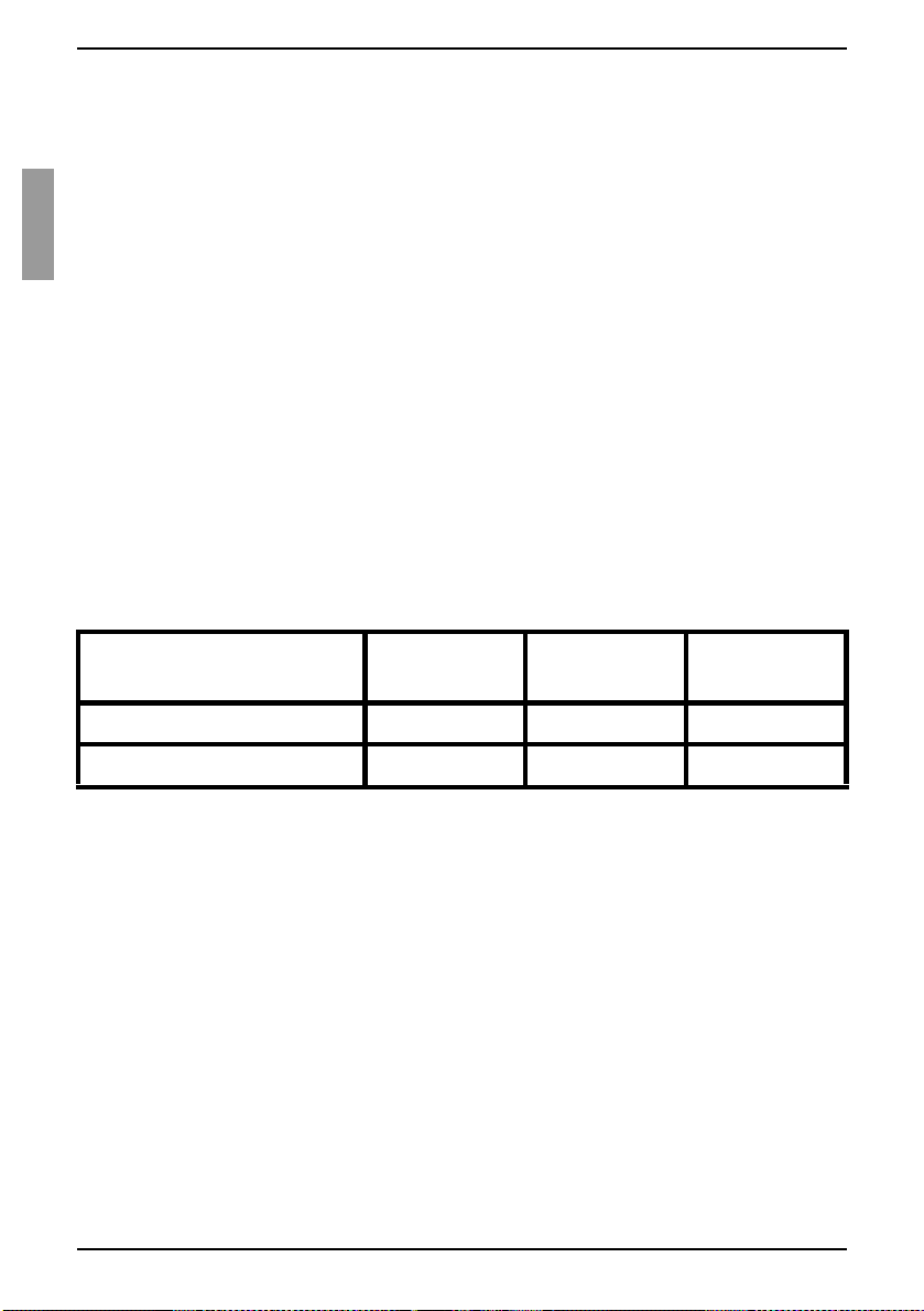
Anpassen der Mauseinstellungen Installation
2.8 Anpassen der Mauseinstellungen
Bevor ein Computer, der an die KVM s3-1621- oder KVM s3-1641-Einheit
angeschlossen ist, für die Steuerung durch einen Remote-Benutzer verwendet
werden kann, muss die Mausgeschwindigkeit des Zielgeräts eingestellt und die
Mausbeschleunigung deaktiviert werden.
Wenn Sie während einer Remote-Videositzung langsame Mausreaktionen
feststellen, deaktivieren Sie die Mausbeschleunigung im Betriebssystem des
Zielgeräts und stellen Sie die Mausgeschwindigkeit auf 50 % ein.
2.9 Anschließen von älteren Einheitenmodellen
an eine KVM s3-1621- oder KVM s3-1641Einheit
Sie können ältere Einheitenmodelle in die bestehende Konfiguration integrieren. In
einem gestuften System kann an jedem ARI-Port ein Zielgerät eingerichtet werden.
Wenn ältere Modelle unter der KVM s3-1621- oder KVM s3-1641-Einheit gestuft
werden, muss sich die KVM s3-1621- oder KVM s3-1641-Einheit auf der obersten
Stufungsebene befind en. Im Fol gen den sind ält ere Mo del le aufg eli stet, die mit der
Konfiguration der KVM s3-1621- oder KVM s3-1641-Einheiten kompatibel sind:
In Tabelle 1 sind ältere KVM-Einheitenmodelle aufgelistet.
Älteres Einheitenmodell Remote-
Benutzer
KVM s2-0801 (analog) 0 1 8
KVM s2-1602 (analog) 0 1 16
Tabelle 1: Ältere KVM-Einheitenmodelle
Befestigen Sie die ältere Einheit im Rack und beachten Sie dabei die geltenden
Anweisungen.
Führen Sie einen der folgenden Schritte durch:
• Schließen Sie Tastatur-, Bildschirm- und Mausstecker eines KVM-IA an den
lokalen Port an der gestuf ten Einhei t a n und schließ en Sie ein Ende eines C AT
5-Kabels an das Ende des KVM s2-Adapter PS/2-VGA KVM-IA an.
-oder-
• Schließen Sie ein Ende eines CAT 5-Kabels direkt an den ACI-Port (Analog
Console Interface) d er gestuf ten Einh eit an. (Wenn Sie nicht si cher sind , ob die
gestufte Einheit über einen ACI-Port verfügt, schlagen Sie in der Installationsund Bedienungsanleitung der gestuften Einheit nach.)
Schließen Sie das andere Ende des CAT 5-Kabels an einen verfügbaren ARI-Port
auf der Rückseite der KVM s3-1621- oder KVM s3-1641-Einheit an.
14
Lokale
Benutzer
ARI-Ports
590-591-609B
Page 83

Installation Anschließen eines nicht kompatiblen Switch-Modells
Schalten Sie die mit den gestuften Einheiten verbundenen Zielgeräte aus und
wieder ein und beachten Sie dabei die geltenden Anweisungen.
Schalten Sie die gestuften Einheiten aus und wieder ein, damit der lokale Port den
KVM-IA erkennt.
Wiederholen Sie die Schritte 1 bis 5 für alle gestuften Einheiten, die an das
Switching-System angeschlossen werden sollen.
Das Switching-System führt die beiden Einheiten automatisch zusammen.
Alle Zielgeräte, die mit den gestuften Einheiten verbunden sind, werden in der
Zielgeräteliste der OSCAR-Benutzeroberfläche in der KVM s3-1621- oder KVM
s3-1641-Haupteinheit angezeigt. Wenn jedoch eine ältere Einheit an einen KVM
s2-Adapter PS/2-VGA KVM-IA angeschlossen ist, werden in der Einheitenliste der
OSCAR-Benutzeroberfläche sowohl die primäre KVM s3-1621- oder KVM s3-1641Einheitenportnummer als auch die durch einen Bindestrich getrennte sekundäre
Einheitenportnummer angezeigt. Die Spalte „Port“ für eine sekundäre ältere Einheit
kann also beispielsweise 01-02 enthalten, wobei 01 der primäre Port und 02 der
sekundäre Port ist.
2.9.1 Anschließen eines nich t kompatiblen Switch-
Modells
Es besteht die Möglichkeit, Einheiten anzuschließen, die nicht in der Tabelle weiter
vorne aufgelistet sind. Nicht kompatible Einheiten unterstützen die nahtlose Stufung
nicht und Geräte, die an eine nicht kompatible Einheit angeschlossen sind, werden im
OSCAR-Menü der KVM s3-1621- oder KVM s3-1641-Einheit nicht angezeigt. Es wird
lediglich der Name angezeigt, der einer nicht kompatiblen Einheit zugewiesen wurde.
So können Sie von der KVM s3-1621- oder KVM s3-1641-Einheit auf eine nicht
kompatible E inheit zugr eifen:
Aktivieren Sie die OSCAR-Benutze r ob erflä che.
Wählen Sie die nicht kompatible Einheit aus. Das OSCAR-Menü für die nicht
kompatible Einheit wird eingeblendet und alle mit der Einheit verbundenen Geräte
werden in der Geräteliste angezeigt.
Wählen Sie das Gerät aus, das mit der nicht kompatiblen Einheit verwendet
werden soll.
Die Verbindung mit diesem Gerät wird nun hergestellt.
So können Sie von einem nicht kompatiblen Gerät auf die KVM s3-1621- oder
KVM s3-1641-Einheit zugreifen:
Aktivieren Sie die OSCAR-Benutze r ob erflä che.
Dadurch wird die OSCAR-Benutzeroberfläche sowohl für die KVM s3-1621- oder KVM s3-1641Einheit als auch für die nicht kompatible Einheit aktiviert.
590-591-609B
15
Page 84

Einrichten der KVM s3-1621- und KVM s3-1641-Einheiten Installation
Wählen Sie in d er OSCAR -Be nut ze robe rfläche das Gerät aus , d as m it der KVM s 3-
1621- oder KVM s3-1641-Einheit verwendet werden soll.
2.10 Einrichten der KVM s3-1621- und KVM
s3-1641-Einheiten
Die KVM s3-1621- und KVM s3-164 1-Einhe iten b ieten I hnen d ie Mögli chkeit, j eden Po rt
der Einheit automatisch erkennen und konfigurieren zu lassen. In Kapitel 3 finden Sie
detaillierte Anweisungen bezüglich der benutzerdefinierten Namensvergabe und der
Einrichtung und Konfiguration mit der OSCAR-Benutzeroberfläche.
16
590-591-609B
Page 85

3 Normalbetrieb
3.1 Steuern des Switching-Systems über den
Analogport
Die KVM s3-1621- und KVM s3-1641-Einheiten verfügen auf der Rückseite über Ports,
an die Sie zum direkten analogen Zugriff Tastatur, Bildschirm und Maus anschließen
können. Die KVM s3-1621- und KVM s3-1641-Einheiten verwenden die OSCARBenutzeroberfläche mit intuitiven Menüs zur Konfiguration des Switching-Systems und
zur Auswahl der Zielgeräte. Switches können durch benutzerdefinierte Namen
identifiziert werden.
3.2 Aufrufen der OSCAR-Benutzeroberfläche
Um Zielgeräte im Switching-System über die OSCAR-Benutzeroberfläche und eine
KVM-Verbindung mit dem Analogport anzuzeigen, zu konfigurieren und zu steuern,
führen Sie einen der folgenden Schritte durch:
Betätigen Sie die Taste Druck
-oder-
Betätigen Sie die Taste Strg
Sekunde, um die OSCAR-Benutzeroberfläche aufzurufen.
Diese Tastenfolgen können immer dann alternativ verwendet werden, wenn in diesem
Handbuch die Taste Druck
Aufrufen der OSCAR-Benutzeroberfläche verwendet werden können, klicken Sie auf
Setup - Menü.
Die folgende Abbildung zeigt ein Beispiel des Hauptmenüs der OSCAR-Benutzeroberfläche.
, um die OSCAR-Benutzerberfläche aufzurufen.
, Alt oder die Umschalttaste zweimal innerhalb einer
angegeben ist. Um festzulegen, welche Tastenfolgen zum
590-591-609B
17
Page 86

Aufrufen der OSCAR-Benutzeroberfläche Normalbetrieb
Abbildung 8: Beispiel eines Hauptmenüs
Das Hauptmenü listet die Zielgeräte im Switching-System auf. Sie können die Liste der
Zielgeräte nach Namen, EID- oder Port-Nummern sortieren, indem Sie auf die
entsprechende Schaltfläche Name, EID oder Port klicken .
Die Spalte Port zeigt den ARI-Port, an den das jeweilige Zielgerät angeschlossen ist.
Wenn eine ältere Einheit an eine KVM s3-1621- oder KVM s3-1641-Einheit
angeschlossen ist, wird zuerst die Nummer des ARI-Ports und dann die Nummer des
Einheitenports angezeigt, an den das Zielgerät angeschlossen ist. In Abbildung8 auf
Seite 18 ist zum Beispiel das Z ielgerät m it dem Namen „And ers“ mit ARI-Port 06 un d die
Einheit mit Port 01 verbunden.
Der Status jedes Zielgeräts im Switching-System wird durch ein oder mehrere
Statussymbole in der rechten Spalte des Bildschirms gekennzeichnet. In Tabelle 2
werden die Statussymbole beschrieben.
Symbol Beschreibung
Der KVM-IA ist online (grüner Kreis).
Der KVM-IA ist offline oder funktioniert nicht einwandfrei.
Das Zielgerät ist über eine ältere Einheit gestuft. Das Zielgerät und die
ältere Einheit sind online und werden mit Strom versorgt.
Tabelle 2: Statussymbole der OSCAR-Benutzeroberfläche
18
590-591-609B
Page 87

Normalbetrieb Einstellen der Zeitverzögerung
Das Zielgerät ist über eine ältere Einh eit ges tuft . Die ältere Einheit is t of fline
oder wird nicht mit Strom versorgt.
Der KVM-IA wird aktualisiert (gelber Kreis ). We nn diese s Symbol ang ezeig t
wird, dürfen Sie die Einheit und die verbundenen Zielgeräte nicht aus- und
einschalten und den KVM-IA nich t trennen , da ble ibend e Schäd en am KV MIA die Folge sein könnten.
Auf den KVM-IA wird über den angezeigten Benutzerkanal zugegriffen
(grüner Kanalbuchstabe).
Der KVM-IA wird durch den angezeigten Benutzerkanal blockiert (schwarzer Kanalbuchstabe). Bei sp iel : In Abb ild ung8 auf Seite 18 wird Förster von
Benutzer C angezeigt, während dadurch der Zugriff auf Anders, Borell und
Enderle, die an denselben KVM-IA angeschlossen sind, blockiert ist.
Es besteht eine Virtual Media-Verbindung mit dem Zielgerät, das mit dem
angezeigten Benutzerkanal verbunden ist (blauer Buchstabe).
Tabelle 2: Statussymbole der OSCAR-Benutzeroberfläche
3.3 Einstellen der Zeitverzögerung
Sie können festlegen, wie viel Zeit zwischen dem Betätigen der Taste Druck und dem
Aufrufen der OSCAR-Benutzeroberfläche vergeht.
Betätigen Sie die Taste Druck
Klicken Sie im Hauptmenü auf Setup - Menü.
Geben Sie im Feld Zeitverzögerung die Anzahl an Sekunden ein, die zwischen
dem Betätigen der Taste Druck
vergehen sollen.
, um die OSCAR-Benutzeroberfläche aufzurufen.
und dem Aufrufen der OS CA R-Benutzeroberfläche
3.4 Verbinden eines Benutzers mit einem
Zielgerät
Wählen Sie im Hauptmenü der OSCAR-Benutzeroberfläche ein Zielgerät aus, mit dem
Sie eine Verbindung herstellen möchten. Wenn Sie ein Zielgerät auswählen, werden
Tastatur und Maus automatisch auf die richtigen Einstellungen für das Zielgerät
konfiguriert.
Betätigen Sie die Taste Druck
führen Sie dann einen der folgenden Schritte aus, um ein Zielgerät auszuwählen:
• Doppelklicken Sie im Hauptmenü auf den Namen, die EID- oder die
Portnummer des Zielgeräts.
oder
• Geben Sie die Portnummer ein und betätigen Sie die Eingabetaste
oder
• Geben Sie die ersten Buchstaben oder Ziffern des Namens bzw. der EID-
Nummer des Zielgeräts ein und betätigen Sie die Eingabetaste
590-591-609B
, um die OSCAR-Benutzeroberfl äc he au fzu rufe n und
.
.
19
Page 88

Auswählen des vorherigen Zielgeräts Normalbetrieb
3.5 Auswählen des vorherigen Zielgeräts
Sie können zwischen zwei ausgewählten Zielgeräten hin- und herschalten, indem
Sie die Taste Druck
und dann die Rücktaste betätigen.
3.6 T rennen der Verbindung zwischen Benutzer
und Zielgerät
Betätigen Sie die Taste Druck und dann Alt+0. Das Statusflag Frei auf der OSCAR-
Benutzeroberfläche zeigt an, dass der Benutzer nicht mit einem Zielgerät
verbunden ist.
3.7 Verwenden der OSCAR-Benutzeroberfläche
In Tabelle 3 werden die Tasten, Tastenkombinationen und Mausaktionen beschrieben,
die Sie in der OSCAR-Benutzeroberfläche verwenden können. Zwei oder mehr
Tastennamen oder Mausaktionen, die durch Kommas voneinander getrennt sind,
zeigen eine Folge von Aktionen an. Zwei oder mehr Tastennamen oder Mausaktionen,
die durch ein Pluszeichen (+) voneinander getrennt sind, zeigen eine Kombination von
Aktionen an, d. h., sie werden gleichzeitig ausgeführt.
Sie können die Haupttastatur oder die Zehnertastatur zur Eingabe von Ziffern
verwenden. Eine Ausn ahme ist die Eingab e der Tastenko mbinat ion Alt
0 (Null) der Haupttastatur verwendet w erden.
+0, hier muss di e
T aste,
Wirkung
Tastenkombination
oder Mausaktion
Druck; Strg, Strg;
Umschalt, Umschalt
oder Alt, Alt
Druck, Druck
F1
Tabelle 3: Grundlagen der OSCAR-Navigation
20
Die OSCAR-Benutzeroberfläche wird aufgerufen. Um
festzulegen, welche Tastenfolgen zum Aufrufen der OSCAR-
Benutzeroberfläche verwendet werden können, klicken Sie
auf Setup - Menü.
Der Tastenanschlag Druck wird an das aktuell ausgewählte
Zielgerät gesendet. Das heißt, der Bildschirminhalt des
Zielgeräts wird erfasst.
Wenn die Taste Druck
Tastenfolge zum Aufrufen von OSCAR ausgewählt wurde,
müssen Sie die Taste Druck
Bildschirminhalt des Zielgeräts zu erfass en.
Hilfe zum aktuellen Bildschirm wird angezeigt.
über Setup - Menü nicht als
nur einmal betätigen, um den
590-591-609B
Page 89

Normalbetrieb Verwenden der OSCAR-Benutzeroberfläche
T aste,
Wirkung
Tastenkombination
oder Mausaktion
Esc Im OSCAR-Hauptmenü: Die OSCAR-Benutzeroberfläche
wird geschlossen und das Status-Flag wird wieder auf dem
Desktop angezeigt.
In allen anderen Dialogfeldern: Das aktuelle Dialogfeld wird
geschlossen, ohne die Änderungen zu speichern und die
Anzeige kehrt zum vorherigen Dialogfeld zurück.
In Popup-Fenstern: Das Popup-Fenster wird geschlossen
und die Anzeige kehrt zum aktuellen Dialogfeld zurück.
+X Das aktuelle Dialogfeld wird geschlossen, ohne die
Alt
Änderungen zu speichern und die Anzeige kehrt zum
vorherigen Dialogfeld zurück.
Alt
+O Durch Klicken auf OK kehrt die Anzeige zum vorherigen
Dialogfeld zurück.
Alt
+Portnummer Auswahl eines Zielgeräts, das gescannt werden soll; die
Portnummer steht für die Portnummer des Zielgeräts.
Eingabetaste
Ein Switching im Hauptmenü wird abgeschlossen und die
OSCAR-Benutzeroberfläche wird verlassen.
Durch Klicken auf ein editierbares Feld wird der zu
bearbeitende Text ausgewählt und die Nach-Rechts- und
Nach-Links-Tasten werden aktiviert, um den Cursor zu
bewegen. Drücken Sie die Eingabetaste, um den
Bearbeitungsmodus zu beenden.
Druck, Rücktaste
Druck, Alt
Druck, Pause
Pfeil-nach-oben- oder
Pfeil-nach-unten-Taste
Tabelle 3: Grundlagen der OSCAR-Navigation (Fortsetzung)
590-591-609B
+0 Die Verbindung des Benutzers mit dem ausgewählten
Rückkehr zum zuvor ausgewählten Zielgerät.
Zielgerät wird getrennt. Beachten Sie, dass die Null auf der
Haupttastatur eingegeben werden muss, nicht auf der
Zehnertastatur.
Der Bildschirmschoner wird umgehend gestartet und der
Benutzer gesperrt, wenn der Bildschirmschoner
kennwortgeschützt ist.
Der Cursor wird zeilenweise in einer Liste bewegt.
21
Page 90

Anschließen von lokalem Virtual Media Normalbetrieb
T aste,
Wirkung
Tastenkombination
oder Mausaktion
Nach-Rechts-Taste
oder Nach-Links-Taste
oder Bild ab Blättern durch eine Liste oder ein Hilfefenster.
Bild auf
Pos1 oder Ende Der Cursor wird an den Anfang oder das Ende einer Liste
Entf
Tabelle 3: Grundlagen der OSCAR-Navigation (Fortsetzung)
Bei der Bearbeitung von Text in einem Feld: Der Cursor wird
innerhalb des Textfelds bewegt.
Alle anderen V erwendungen: Der Curs or wird spaltenwei se in
einer Liste bewegt.
bewegt.
Die ausgewählten Zeichen in einem Feld oder das
ausgewählte Element in der Scan-Liste werden gelöscht.
Weitere Informati on en zu Sca n-L isten finden Sie in Ab sc hni tt
3.12 Scannen des Switching-Sys tem s auf Seit e 42.
3.8 Anschließen von lokalem Virtual Media
Virtual Media kann direkt über den USB-Port der Switches an die KVM s3-1621- und
KVM s3-1641-Einheiten angeschlossen werden.
Alle USB-Ports werden einer einzelnen Virtual Media-Sitzung zugewiesen
und können nicht unabhängig zugeordnet werden.
Drücken Sie die Taste Druck
Hauptmenü wird geöffnet.
Verbinden Sie den Benutzer mit dem Zielgerät, mit dem Sie eine Virtual Media-
Sitzung starten möchten. Markieren Sie den Namen des Zielgeräts mithilfe der
Pfeiltasten und betätigen Sie dann die Eingabetaste
Betätigen Sie die Taste Druck, um die OSCAR-Benutzeroberfläche erneut zu
starten. Das Dialogfeld „Virtual Media“ wird geöffnet.
Aktivieren Sie eines oder mehrere der folgenden Kontrollkästchen:
• Gesperrt: Aktivieren Sie dieses Kontrollkästchen, um festzulegen, dass auch
die Virtual Media-Sitzung getrennt wird, wenn der Benutzer von einem
Zielgerät getrennt wird.
oder
• Reserviert: Aktivieren Sie dieses Kontrollkästchen, um festzulegen, dass auf
die Virtual Media-Verbindung nur mit Ihrem Benutzernamen zugegriffen
werden kann. Somit kann kein anderer Benutzer eine Verbindung mit diesem
Zielgerät herstelle n. Die Sit zung i st rese rviert, we nn sowo hl Gesperrt als auch
Reserviert ausgewählt wurden.
oder
22
, um die OSCAR-Benutzeroberfläche aufzurufen. Das
.
590-591-609B
Page 91
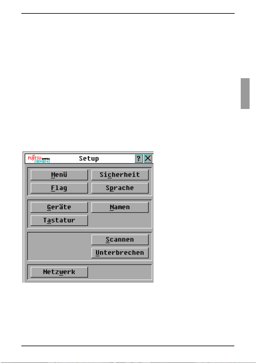
Normalbetrieb Konfigurieren der Einheiten und der OSCAR-Benutzeroberfläche
• CD-ROM: Aktivieren Sie dieses Kontrollkästchen, um eine Virtual Media-CDVerbindung mit einem Zielgerät herzustellen. Deaktivieren Sie dieses
Kontrollkästchen, um die Verbindung zu beenden.
• Massenspeicher: Aktivieren Sie dieses Kontrollkästchen, um eine Virtual
Media-Massenspeicher-Verbindung mit einem Zielgerät herzustellen.
Deaktivieren Sie dieses Kontrollkästchen, um die Verbindung zu beenden.
-oder-
• Schreibzugriff: Aktivieren S ie dieses Kontro llkästch en, damit da s verbunde ne
Zielgerät während der Virtual Media-Sitzung Daten auf das Virtual-MediaGerät schreiben kann. Der Lesezugriff ist während Virtual Media-Sitzungen
immer aktiviert.
Klicken Sie auf OK.
3.9 Konfigurieren der Einheiten und der OSCAR-Benutzeroberfläche
Rufen Sie die OSCAR-Benutzeroberfläche auf und klicken Sie auf Setup. In
Abbildung 9 wird das Dialogfeld „Setup“ gezeigt.
Abbildung 9: Dialogfeld „Setup“
590-591-609B
23
Page 92

Zuweisen von Zielgerätenamen Normalbetrieb
In Tabelle 4 werden die Option en bes ch rieben, die im Dialogfe ld „Setu p“ v erf ügbar sind.
Option Zweck
Menü Sortiert die Liste der Zielgeräte nach Name, EID-Nummer oder
Portnummer des Zielgeräts. Einstellen einer Zeitverzögerung, um
festzulegen, wie viel Zeit zwischen dem Betätigen der Taste Druck
und dem Aufruf der OSCAR-Benutzeroberfläche vergeht.
Sicherheit Einrichten von Kennwörtern, um den Zugriff auf die Zielgeräte
einzuschränken. Aktivieren des Bildschirmschoners.
Flag Ändern von Anzeigeeinstellungen wie Zeit, Farbe und Position des
Status-Flags.
Sprache Festlegen der Sprache, in der die Benutzeroberfläche angezeigt wird.
Geräte Festlegen der Anzahl an Ports, die sich an den angeschlossenen
gestuften Einheiten befinden.
Namen Zuweisen eines eindeutigen Namens für jedes Zielgerät.
Tastatur Einstellen des länderspezifischen Tastaturlayouts.
Scannen Einrichten eines benutzerdefinierten Scan-Schemas für bis zu 16
Zielgeräte.
Unterbrechen Festlegen von Einstellungen zum Unterbrechen der Sitzungen.
Netzwerk Einstellen von Netzwerkgeschwindigkeit und -konfiguration,
IP-Adresse, Netzmaske und Gateway für das Switching-System.
Tabelle 4: Setup-Funktionen zur Verwaltung von Routineaufgaben für die Zielgeräte
3.9.1 Zuweisen von Zielgerätenamen
Verwenden Sie das Dialogfeld „Namen“, um individuelle Zielgeräte nach Namen und
nicht nach Portnummern zu identi fiz ier en. D ie Name ns lis te wird imm er nach
Portnummer sortiert. Namen werden im KVM-IA gespeichert. Selbst wenn das Kabel
oder das Zielgerät an einen anderen ARI-Port angeschlossen wird, werden der Name
und die Konfiguration von den KVM s3-1621- und KVM s3-1641-Einheiten erkannt.
Wenn ein Zielgerät ausgeschaltet ist, kann der Name des KVM-IA nicht geändert
werden.
Betätigen Sie die Taste Druck
Das Hauptmenü wird geöffnet.
Klicken Sie auf Setup - Namen. Das Dialogfeld „Namen“ wird geöffnet.
24
, um die OSCAR-Benutzeroberfläche aufzurufen.
590-591-609B
Page 93

Normalbetrieb Zuweisen von Zielgerätenamen
Abbildung 10: Dialogfeld „Namen“
Wenn die KVM s3-1621- oder KVM s3-1641-Einheit neue KVM-IAs erkennt, wird die
Liste im Dialogfeld automatisch aktualisiert. Der Mauszeiger ändert sich während der
Aktualisierung in ein Sanduhrsymbol. Erst nach abgeschlossener Aktualisierung der
Liste werden wieder Tastatur- und Mauseingaben akzeptiert.
Wählen Sie den Namen oder die Portnummer des gewünschten Zielgeräts im
Dialogfeld „Namen“ aus und klicken Sie auf die Schaltfläche Ändern. Das
Dialogfeld „Namen ändern“ wird geöffnet.
590-591-609B
25
Page 94
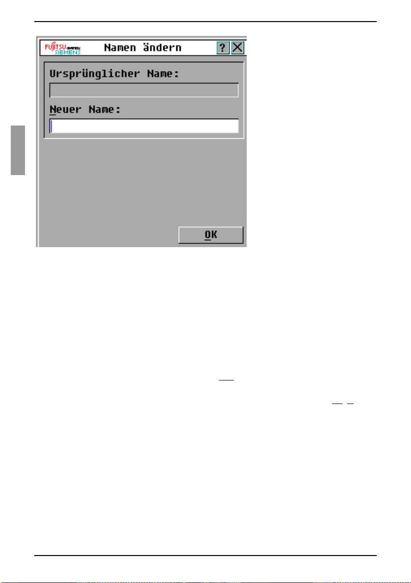
Zuweisen von Einheiten- und Gerätetypen Normalbetrieb
Abbildung 11: Dialogfeld „Namen ändern“
Geben Sie einen Namen in das Feld Neuer Name ein. Namen der Zielgeräte können
bis zu 15 Zeichen lang sein. Gültig e Zeic hen s ind A-Z, a-z, 0 -9, Leerz eich en und
Bindestriche.
Klicken Sie auf OK, um den neuen Namen in das Dialogfeld „Namen“ zu
übernehmen. Die Auswahl wird erst gespeichert, wenn Sie im Dialogfeld „Namen“
auf OK klicken.
Wiederholen Sie die Schritte 1 bis 3 für jedes Zielgerät im Switching-System.
Klicken Sie im Dialogfeld Namen auf OK, um die Änderungen zu speichern. Wenn
Sie das Dialogfeld verlassen möchten, ohne die Änderungen zu speichern, klicken
Sie auf das X oder betätigen Sie die Taste Esc.
Die EID wird als Standardname verwendet, wenn dem KVM-IA kein Name zugewiesen
wurde. Um die Zielgeräte alpha betisch nach Namen auf zulisten, dr ücken Sie Alt
klicken Sie im Hauptmenü auf Name.
+N oder
3.9.2 Zuweisen von Einheiten- und Gerätetypen
Die KVM s3-1621- und KVM s3-1641-Einheiten erkennen angeschlossene gestufte
Einheiten automatisch. Sie müssen aber die Anzahl der Ports der gestuften Einheiten
im Dialogfeld „Geräte“ angeben. Fujitsu Siemens Console Switches und andere
Vorgängermodelle werden in der Kategorie „Typ“ für die gestuften Einheiten angezeigt.
Die Schaltfläche Ändern wird aktiviert, wenn Sie eine konfigurierbare Einheit in der
Liste auswählen. Über diese Schaltfläche können Sie der Einheit die richtige Anzahl an
Ports zuweis en.
26
590-591-609B
Page 95

Normalbetrieb Zuweisen von Einheiten- und Gerätetypen
3.9.2.1 Zugriff auf das Dialogfeld „Geräte“
Betätigen Sie die Taste Druck
, um die OSCAR-Benutzeroberfläche aufzurufen.
Das Hauptmenü wird geöffnet.
Klicken Sie auf Setup - Geräte. Das Dialogfeld „Geräte“ wird geöffnet.
Abbildung 12: Dialogfeld „Geräte“
Wenn die KVM s3-1621- oder KVM s3-1641-Einheit eine gestufte Einheit erkennt,
ändert sich die Portnummerierung, so dass alle Zielgeräte unter dieser Einheit
dargestellt werden.
Wenn die ältere Einheit beispielsweise an ARI-Port 6 angeschlossen ist, wird der Port
der älteren Einheit als 06 aufgelistet und jedes daran angeschlossene Zielgerät wird
nachfolgend als 06-01, 06-02 usw. nummeriert.
3.9.2.2 Zuweisen des Switch-Typs
Wählen Sie die Portnummer im Dialogfeld „Geräte“ aus.
Klicken Sie auf Ändern. Das Dialogfeld „Gerät ändern“ wird geöffnet.
590-591-609B
27
Page 96

Ändern des Anzeigeverhaltens Normalbetrieb
Abbildung 13: Dialogfeld „Gerät ändern“
Wählen Sie die Anzahl an Ports aus, die von der gestuften älteren Einheit
unterstützt werden oder geben Sie die Anzahl ein und klicken Sie auf OK.
Wiederholen Sie die Schritte 1 - 3 für jeden Port, dem ein Switch-Typ zugewiesen
werden soll.
Klicken Sie im Dialogfeld „Geräte“ auf OK, um die Einstellungen zu speichern.
3.9.3 Ändern des Anzeigeverhaltens
Im Dialogfeld „Menü“ kann die Reihenfolge der Zielgeräte geändert und eine
Zeitverzögerung für die O SCAR-Benutze roberflä che einge stellt werden . Die Einstellu ng
der Anzeigereihenfolge wirkt sich auf die Reihenfolge der Zielgeräte in mehreren
Fenstern aus, unter anderem im Hauptmenü und im Dialogfeld „Geräte“.
Drücken Sie die Taste Druck
Das Hauptmenü wird geöffnet.
Klicken Sie auf Setup - Menü. Das Dialogfeld „Menü“ wird geöffnet.
28
, um die OSCAR-Benutzeroberfläche aufzurufen.
590-591-609B
Page 97

Normalbetrieb Ändern des Anzeigeverhaltens
Abbildung 14: Dialogfeld „Menü“
3.9.3.1 Auswählen der Anzeigereihenfolge für Zielgeräte
Klicken Sie auf eine der folgenden Schaltflächen:
• Klicken Sie auf Name, um die Zielgeräte alphabetisch nach Namen
zu sortieren.
-oder-
• Klicken Sie auf EID, um die Zielgeräte numerisch nach EID-Nummern
zu sortieren.
-oder-
• Klicken Sie auf Port, um die Zielgeräte numerisch nach Portnummern
zu sortieren.
Klicken Sie auf OK.
3.9.3.2 Auswählen der Tastenkombinationen
Wählen Sie im Bereich OSCAR aufrufen die Tastenkombinationen aus, die Sie
zum Aufrufen der OSCAR-Benutzeroberfläche verwenden möchten und drücken
Sie dann die ausgewählte Kombination auf der Tastatur.
Klicken Sie auf OK.
3.9.3.3 Einstellen der Zeitverzögerung
Sie können eine Zeitverzögerung einstellen, damit Sie über die Tastatur ein
Zielgerät auswählen können, ohne die OSCAR-Benutzeroberfläche aufzurufen.
Die Zeitverzögerung legt fest, wie viel Zeit zwischen dem Betätigen der Taste
Druck
und dem Aufruf der OSCAR-Benutzeroberfläche vergeht.
590-591-609B
29
Page 98
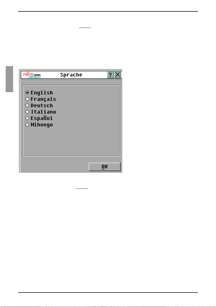
Auswählen der Anzeigensprache Normalbetrieb
Geben Sie die Sekundenzahl (0-9) ein, um festzulegen, wie viel Zeit zwischen
dem Betätigen der Taste Druck
vergehen soll. Bei Eingabe von 0 tritt keine Zeitverzögerung auf.
Klicken Sie auf OK.
und dem Aufruf der OSCAR-Benutzeroberfläche
3.9.4 Auswählen der Anzeigensprache
Im Dialogfeld „Sprache“ können Sie die Sprache ändern, in der die OSCARBenutzeroberfläche angezeigt wird.
Abbildung 15: Dialogfeld „Sprache“
Betätigen Sie die Taste Druck
Das Hauptmenü wird geöffnet.
Klicken Sie auf Setup - Sp rache. Das Dialogfeld „Sprache“ wird geöffnet.
Wählen Sie im Dialogfeld „Sprache“ die gewünschte Sprache aus und klicken
Sie auf OK.
, um die OSCAR-Benutzeroberfläche aufzurufen.
3.9.5 Steuern des Status-Flags
Das Status-Flag wird auf Ihrem Desktop angezeigt und gibt den Namen oder die EIDNummer des ausgewählten Zielgeräts oder den Statu s de s au sgewählten Ports an. Sie
können festlegen, welche Informationen im Flag angezeigt werden, welche Farbe das
Flag hat, ob der Desktop durch da s Flag sichtb ar ist, ob das Flag ständig ange zeigt wird
und in welcher Po sition a uf dem Des ktop es an gezeigt wird. Ta belle 5 zeigt Beispiele für
Status-Flags.
30
590-591-609B
Page 99

Normalbetrieb Steuern des Status-Flags
Status-Flag Beschreibung
Anzeige des Flag-Typs nach Namen.
Anzeige des Flag-Typs nach EID-Nummer.
Flag zeigt an, dass die Verbindung des Benutzers mit alle n
Systemen getrennt wurde.
Tabelle 5: Status-Flags der OSCAR-Benutzeroberfläche
Betätigen Sie die Taste Druck. Das Hauptmenü wird geöffnet.
Klicken Sie auf Setup - Flag. Das Dialogfeld „Flag-Setup“ wird geöffnet.
Abbildung 16: Dialogfeld „Flag-Setup“
Legen Sie eine oder mehrere der folgenden Einstellungen fest:
• Wählen Sie Name oder EID aus, um die auf dem Flag angezeigten
Informationen festzulegen.
• Wählen Sie Anzeigen aus, um das Flag ständig anzuzeigen oder Zeit,
um das Flag jeweils nur 5 Sekunden lang nach der Auswahl eines Zielgeräts
anzuzeigen.
• Wählen Sie unter Anzeigefarbe die Farbe des Flags aus.
• Wählen Sie Deckend, um das Flag in deckender Farbe anzuzeigen oder
Transparent, damit der Desktop durch das Flag sichtbar ist.
590-591-609B
31
Page 100

Einstellen der länderspezifischen Tastatur Normalbetrieb
• Führen Sie folgende Schritte durch, um die Position des Flags festzulegen:
• Klicken Sie auf Positionieren.
• Halten Sie die linke Maustaste auf der Titelleiste des Dialogfelds
„Positionieren“ gedrüc kt und ziehen Sie das Dialog feld an die gewü nschte
neue Position.
• Schließen Sie das Dialogfeld „Positionieren“, indem Sie mit der rechten
Maustaste klicken.
Abbildung 17: Dialogfeld „Positionieren“
Klicken Sie auf OK, um die Änderungen zu speichern. Wenn Sie das Dialogfeld
verlassen möchten, ohne die Änderungen zu speichern, kli ck en Sie a uf das X oder
betätigen Sie die Taste Esc
.
3.9.6 Einstellen der länderspezifischen Tastatur
Standardmäßig senden die KVM s3-1621- und KVM s3-1641-Einheiten die
Tastatureinstellungen einer US-Tastatur an die mit den Zielgeräten verbundenen USBKabel. Die Tastatureinstellungen werden auf die Zielgeräte angewendet, wenn diese
eingeschaltet oder neu gestartet werden. Dann werden die Einstellungen im KVM-IA
gespeichert. Wird eine Tastatureinstellung verwendet, die eine andere Sprache
unterstützt als die der Firmware der KVM s3-1621- und KVM s3-1641-Einheiten,
sind falsche Tastaturzuordnungen die Folge.
Wenn mehrere Tastaturen an den lokalen Port angeschlossen sind, müssen sie vom
gleichen Typ (PC oder Mac) sein und die gleichen Spracheinstellungen verwenden.
Es können Probleme auftreten, wenn die US-Tastatureinstellung mit einer anderen
länderspezifischen Tastatur verwendet wird. Die Taste Z auf einer US-Tastatur ist
zum Beispiel am selben Platz wie die Taste Y auf einer deutschen Tastatur.
Im Dialogfeld „Tastatur“ können Sie statt der US-Standardeinstellung eine andere
länderspezifische Tastatur einstellen.
32
590-591-609B
 Loading...