

Siemens HUB-4 Installation Instructions Manual
Installation Instructions
Model HUB-4
Communication Card for NCC WAN/PMI-2 Concentrator
INTRODUCTION The Model HUB-4 Communication Card from Siemens Industry, Inc., mounts in the
CC-5 Card Cage and provides up to four independent data channels, which can be
wired as either Style 4 or Style 7 for communication to the remote XLS, MXL, XL3 or
other UL864 listed local fire alarm panel providing dry relay contacts that can be used
for event monitoring.
The HUB-4 consists of a single Main-2 board on which two COM-2 boards are
installed. In turn, up to two modem or RS-485 Interface blocks can be installed on
each COM-2 board. Each modem block installed provides a single FSK data channel.
Each RS-485 Interface block installed provides a proprietary RS-485 interface channel.
Either a RS-485 Interface or a Modem Block module can be used, dependent on
application. Table 1 describes the connections that can be made.
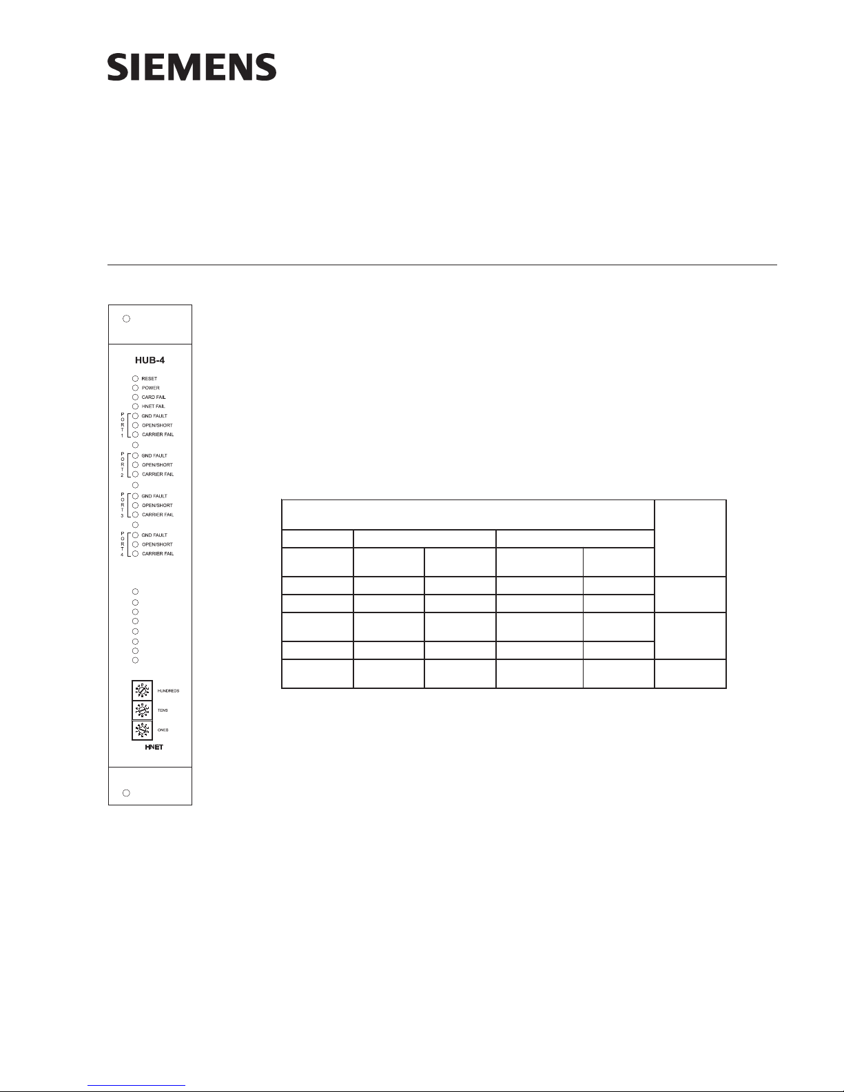
Figure 1
HUB-4 Communication
Card
1ELBAT
LENAP584-SRMEDOM
BssalC
)4elytS(
3LX A/NA/NXMMXMMNAWCCN
LXM A/NA/N003-IMC003-IMC
LXM-ISF W1-MINA/NdnaM1/W1-MIN
SLX-ISF MPR/BUHBUHBUHA/N
rehtO sOIAW
)61-1(
Each of the four data channels is controlled by a separate micro-controller which
provides all background supervision of the data lines (to the remote panel) as well as
sending and receiving Fire Panel information to the primary micro-controller. The
information from these four channels is concentrated into a single data stream and
sent to the NCC WAN via the NIC-C or the PMI-2 Concentrator via HNET. On NCC
WAN, the HUB-4 communicates on each of four ports with either the MMX (XL3
Modem), the CMI-300 (MXL modem), NIM-1 FSI (MXL FSI modem), NIM-1W (MXL
RS-485), RPM (XLS RS-485), HUB-4 (XLS RS-485), HUB-4 (XLS modem) or up to 16
WAIO (Wide Area Input Output) boards. On the PMI-2 Concentrator, the HUB-4
communicates on each of the four ports with either the NIM-1W/NIM-1M (MXL
Modem), NIM-1W (MXL RS-485), RPM (XLS RS-485), HUB-4 (XLS RS-485), or HUB-4
(XLS modem).
AssalC
)7elytS(
sOIAW
)61-1(
A/NA/NNAWCCN
SEPYTNOITCENNOCDNASLENAPERIFDNA4-BUH
BssalC
)4elytS(
kcolBmedoM
alC
Ass
)7elytS(
A/NroNAWCCN
ylno
MP
2-I
rotartnecnoC
ylno
Using the Modem Block module, communication distance is 8 miles (CMI-300/MMX-1)
or 10 miles (HUB-4 to HUB-4) over 18 gauge twisted pair lines depending on the quality
of the communication wires (attenuation cannot exceed -23 dBm [CMI-300/MMX-1] or
P/N 315-099458-9
Building Building
Building
Building Building
Siemens Siemens
Siemens
Siemens Siemens
TT
ecec
hnologies Dihnologies Di
T
ec
hnologies Di
TT
ecec
hnologies Dihnologies Di
IndustryIndustry
Industry
IndustryIndustry
visionvision
vision
visionvision
,,
Inc. Inc.
,
Inc.
,,
Inc. Inc.

-38dBm [HUB-4 to HUB-4] @ 2.5KHz), however, using conditioned data grade leased
lines from the phone company, the distance is unlimited.
Using the RS-485 Interface module, the communication distance is 12,000 feet using
18 gauge twisted pair lines.
OPERATION On NCC WAN, the HUB-4 can communicate using either the CMI-300, MMX, NIM-1W/
NIM-1M or HUB-4 slave Modem supervising the data circuit as well as the connected
MXL or XL3 Control Panel. Each of the four independent HUB-4 channels provides the
means to transmit data to and from the XLS, MXL or XL3 and the NCC WAN Head-End
System. The HUB-4 can also communicate with up to 16 WAIO cards, supervising the
data circuit for them as well as their inputs. Each of the four independent HUB-4
channels provides the means to transmit data to and from the WAIOs and the NCC
WAN head end system. In addition, the HUB-4 can support FSI protocol to communicate to an MXL using a NIM-1W or to an XLS using a HUB-4 slave so that an NCC or a
Desigo CC via the PMI-2 Concentrator will act as the remote management system.
Similarly, the HUB-4 can support FSI protocol to an RPM in an XLS fire system.
The HUB-4 Card is divided into five main sections: four external link sections and a
control section. The control section provides supervision of the HNET data channel
(Connection to the NCC WAN/PMI-2 Concentrator) and receives data from each of the
external links for transmission to the NCC WAN/PMI-2 Concentrator. The control
section also provides on board processor and integrity supervision. When installed in
the XLS system, the HUB-4 operates in slave mode.
Controls and Indicators The front panel of the HUB-4 contains one reset switch, 15 LEDs and three HNET
address switches as shown in Figure 1.
A reset switch is located on the top of the front panel. Pushing the reset switch reinitializes the HUB-4 operation.
The LEDs follow the reset switch and their functions are defined as follows:
POWER (Green) Normally ON. When illuminated, indicates that power
for the HUB-4 is applied to the card.
CARD FAIL (Yellow) Normally OFF. When illuminated, indicates that the
card microprocessor has failed. May illuminate for 2-4
seconds when initially powered.
HNET FAIL (Yellow) When consistantly illuminated, the HUB-4 has de-
tected an HNET loss of supervision of the NCC. When
the HUB-4 detects an HNET failure, it will cause all
configured ports to shut down communication to
remote units. The muted ports will be indicated by a
flashing OPEN/SHORT LED. When flashing rapidly, the
HUB-4 has been addressed via the front panel HNET
address select switches with an inappropriate address,
i.e., address zero, or addressed above 252 decimal.
PORTS 1 – 4 The LEDs for each independent modem block module
Siemens Industry, Inc.
Building Technologies Division
or RS-485 Interface module are referred to as ports.
When all three LEDs are flashing for a specific port,
P/N 315-099458-92
that port is considered to be an unspecified,
unconfigured port that has detected a modem
originate signal or RS-485 data from a remote unit.
GND FAULT (Yellow) Normally OFF. When illuminated, indicates that the
HUB-4 has detected either a negative or positive
ground fault on its field wiring.
OPEN/SHORT (Yellow) Normally OFF. When consistently illuminated, the HUB-
4 has detected an OPEN/SHORT in either the primary or
secondary wired communications line. When flashing,
there is a loss of communications between the HUB-4
main module, and the specific HUB-4 communication
port. If the HNET FAIL LED is also illuminated, this port
has been muted.
CARRIER FAIL (Yellow) Normally OFF. When consistently illuminated, the
HUB-4 has detected CARRIER FAIL with a modem
block or a polling supervision fail with a RS-485
Interface card between the HUB-4 and the remote
device. When flashing, there is a loss of communications between the modem or RS-485 Interface card
and the communications controller of the HUB-4 or
loss of communications between the HUB-4 and the
remote fire system.
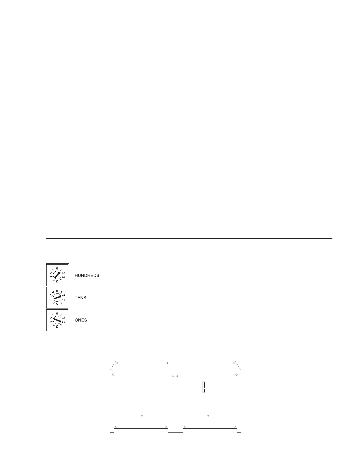
Three rotary dial switches at the bottom of the front panel are used to set the HNET
network address of the HUB-4.
PRE-INSTALLATION Switch and Jumper Settings are required only on HUB-4, Main-2 and HUB-4, COM-2
boards that are not factory preassembled.
1. Network Address Switches: Set the three-digit HNET network address for
the HUB-4 using the three rotary dial switches located near the bottom of
the front panel. (Refer to Figure 1 for the location of the switches.) The
address for the HUB-4 must be the same as the address selected for it in
the NCC WAN/PMI-2 Concentrator. To set the address, turn the pointers on
each of the three dials to the numbers for the selected address. For example, if the address is 123, set the pointer for the HUNDREDS dial to “1”,
set the pointer for the TENS dial to “2”, and set the pointer for the ONES dial
to “3”. The range of allowable addresses is from 001 to 251 (leading zeros
HNET
must be used).
2. HUB-4, Main-2 Board (Switch S2): Currently Not Used. All switches must
be set to the ON position.
HUB-4 MAIN-2
(Bottom side of board)
OFF
ON
12345678
Siemens Industry, Inc.
Building Technologies Division
S2
Figure 2
Location of S2 On HUB-4 Main-2
P/N 315-099458-93
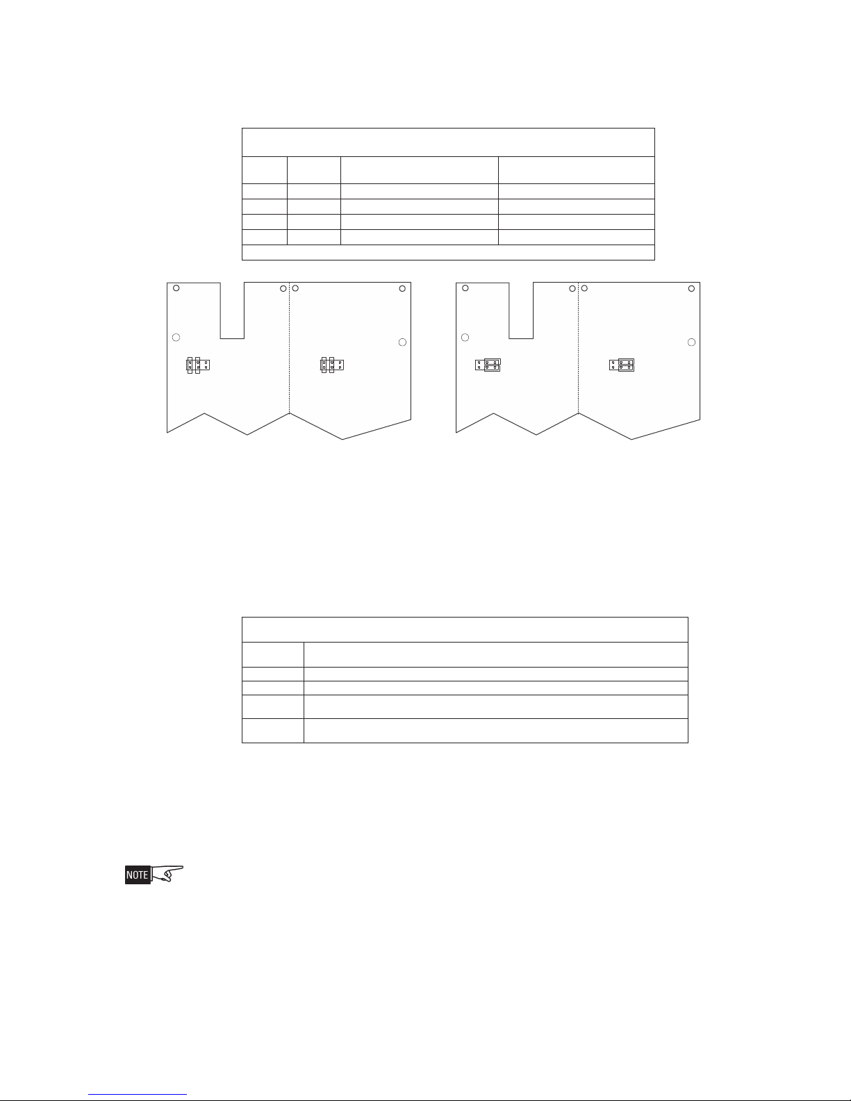
3. HUB-4, COM-2 Board: Make sure that the jumper settings are correct for the
desired application (either Modem Block or RS-485 Interface Module). Refer
to Table 2 and Figure 3 for the correct placement of jumpers on P5 and P6.
2ELBAT
SGNITTESREPMUJ2MOC
*troPrepmuJnoitacilppAeludoMkcolBmedoM
1troP5P
2troP6P
3troP5P
4troP6P4-3,2-16-4,5-3
tacolehtrof4erugiFotrefeR*
,2-16-4,5-3
4-3
4-3,2-16-4,5-3
4-3,2-16-4,5-3
HUB-4,
COM-2
.draob2niaM,4-BUHehtno4-1stroPfonoi
eludoMecafretnI584-SR
noitacilppA
HUB-4,
COM-2
256
1
P5
JUMPER SETTINGS FOR MODEM MODULE JUMPER SETTINGS FOR RS-485 INTERFACE MODULE
256
1
P6
256
1
P5
256
1
P6
Figure 3
Jumper Settings of P5 and P6 on HUB-4, COM-2
HUB-4 Configuration The HUB-4 can be configured to support from one to four independent communica-
tion channels (Modem Block or RS-485 Interface modules). Refer to Table 3 to
determine the required modules for the desired configuration. Modem Block and RS485 Interface modules can not be mixed on a single COM-2 card.
3ELBAT
NOITARUGIFNOC4-BUH
forebmuN
slennahCseludoMderiuqeR
1 eludoMecafretnI584-SR1rokcolBmedoM1,2-MOC4-BUH
2 seludoMecafretnI584-SR2roskcolBmedoM2,2-MOC4-BUH1,2-niaM4-BUH1
3
4
1,2-niaM4-BUH1
lBmedoM2roskcolBmedoM3,2-MOC4-BUH2,2-niaM4-BUH1
tnI584-SR4roseludoM
.seludoMecafre
ecafretnI584-SR1dnaskco
seludoMecafetnI584-SR3roseludoMecafretnI584-SR2dnakcolBmedoM1roseludoM
ecafretnI584-SR2dnaskcolBmedoM2roskcolBmedoM4,2-MOC4-BUH2,2-niaM4-BUH1
HUB-4 Assembly The HUB-4 Assembly consists of the HUB-4 Main-2, two COM-2 boards, and from
one to four Modem Block or RS-485 Interface modules, depending on your desired
configuration. If your HUB-4 is preassembled, complete Steps 1 and 2 below and then
go to Step 9. Refer to Table 4 for correct placement of modem block or RS-485 Interface modules on the HUB-4 Main -2.
When assembling the HUB-4, note that P1, the 2 X 15 receptacle on the HUB-4, Main-2, connects
to Port 1, P2 connects to Port 2, P3 connects to Port 3, and P4 connects to Port 4.
1. Begin connecting the components by following the instructions for the
2. Determine the number of channels (from one to four) that your system will
Siemens Industry, Inc.
Building Technologies Division
Modem Block module, P/N 315-099356, or the RS-485 Interface module, P/
N 315-049930.
require. Install the HUB-4 COM-2 and Modem Block or RS-485 Interface
modules on the HUB-4 Main-2 according to Table 4, page 6.
P/N 315-099458-94
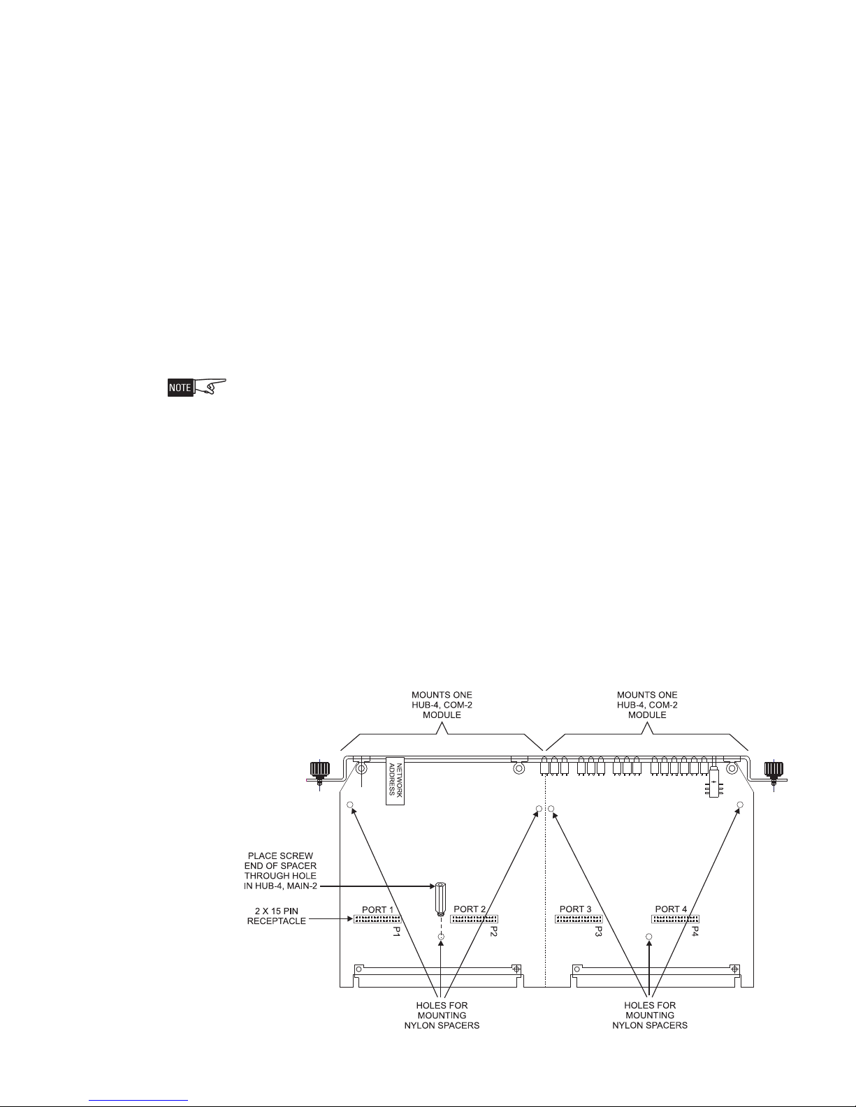
3. Using the three nylon spacers provided with each HUB-4, COM-2, place the
screw end of the spacers through the holes in the top of the HUB-4, Main-2
board. (Refer to Figure 4, page 5.)
4. Secure the spacers in place on the underside of the HUB-4, Main-2 board
with the nylon nuts provided.
5. Connect the HUB-4, COM-2 to the HUB-4, Main-2 by lining up the 2x15
connectors on the HUB-4 COM-2 to the 2x15 receptacles on the HUB-4,
Main-2. Keep in mind that Port 1 is the P1 receptacle, etc. Gently insert the
connectors into the receptacles being careful not to bend the connectors.
6. Note that the spacer holes on the HUB-4, COM-2 board line up with the
spacers on the HUB-4 Main-2 board. (Refer to Figure 5, page 6.)
7. Insert the 3 nylon screws (packaged with the HUB-4, COM-2) through the
holes in the HUB-4, COM-2 into the spacers in the HUB-4, Main-2 and
secure them in place. (Refer to Figure 5, page 6.)
8. If a second HUB-4, COM-2 is required, install it now by following the
previous steps.
When installing Modem Block or RS-485 Interface modules, refer to Table 4 for correct placement
on HUB-4 Main-2.
9. Connect the Modem Block or RS-485 Interface module to the HUB-4, COM2 by lining up the 2x10 connector on the Modem Block or RS-485 Interface
module to the 2x10 receptacle on the HUB-4, COM-2. Gently insert the
connector into the receptacle being careful not to bend the connector.
10. Note that the spacer holes on the Modem Block or RS-485 Interface module
line up with the spacers on the HUB-4 COM-2. (Refer to Figure 5, page 6.)
11. Insert the 3 nylon screws (packaged with the Modem Block or RS-485
Interface module) through the holes in the Modem Block module or RS-485
Interface module into the spacers in the HUB-4, COM-2 and secure them in
place. (Refer to Figure 5, page 6.)
12. If additional Modem Block or RS-485 Interface modules are required, install
them now by following steps 9-11 above.
Figure 4
Spacer Placement on HUB-4, Main-2
Siemens Industry, Inc.
Building Technologies Division
P/N 315-099458-95
 Loading...