

Siemens HTRI-S, HTRI-D, HTRI-R Installation Instructions Manual
Installation Instructions
Models HTRI-S / HTRI-D / HTRI-R
Addressable Switch Interface Modules
INTRODUCTION The SIEMENS Model HTRI Series Addressable
modules, shown in Figure 1, interface direct
shorting devices to the FireFinder-XLS Systems
DLC loop circuit.
The HTRI modules are available in three models.
The HTRI-S and HTRI-R can monitor a normally
open or closed dry contact. The HTRI-S can only
monitor and report the status of the contact,
while the HTRI-R incorporates an addressable
Form C relay. The HTRI-D is a dual input module
that supervises and monitors two sets of
dry contacts.
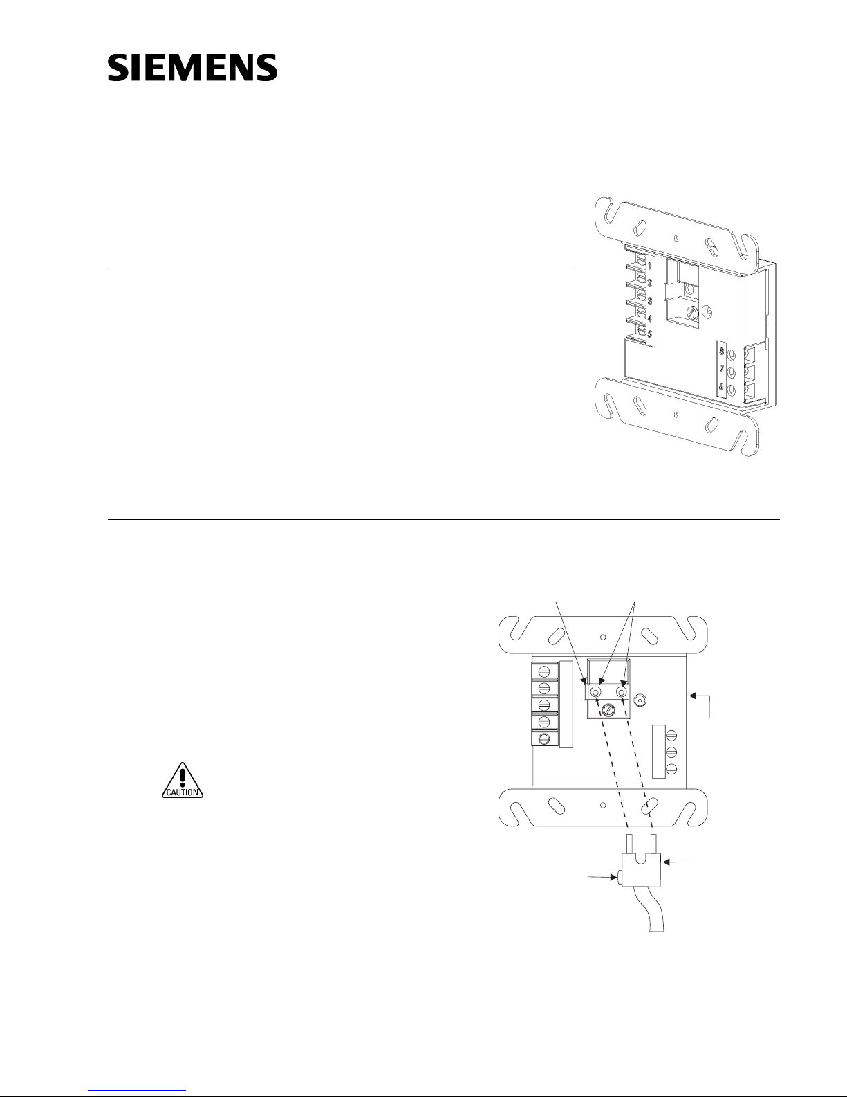
PROGRAMMING Refer to Figure 2 to locate the opening on the HTRI cover that allows access to the
INSTRUCTIONS
programming holes which are on the HTRI printed circuit board.
Figure 1
HTRI Module
To connect the HTRI to the
DPU Programmer/Tester,
insert the plug from the DPU
cable provided with the
Programmer/Tester into the
opening on the front of the
HTRI. Be sure to insert the
locating tab on the plug into
the slot for the locating tab on
the HTRI as shown in Figure 2.
To prevent potential damage
to the DPU DO NOT connect
an HTRI to the DPU until at
least one wire is removed
from terminals 1 or 2 of the
HTRI.
SLOT FOR
LOCATING TAB
1
2
3
4
5
LOCATING
TAB
Figure 2
Connecting The DPU Plug
PROGRAMMING
HOLES
8
7
6
HTRI-S/-D/-R
MODULE
PLUG FROM
DPU
PROGRAMMER/
TESTER
P/N 315-033300-2
Siemens Building Technologies
Fire Safety
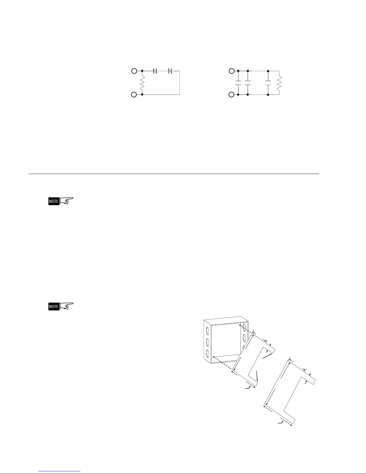
(Refer to Figure 3.) Follow the instructions in the DPU Manual (P/N 315-033260) to
program the HTRI to the desired address. Record the device address on the label
located on the HTRI front panel. The HTRI can now be installed and wired to the
system.
NORMALLY CLOSED SWITCHES
(SEE NOTE 4)
NORMALLY OPEN SWITCHES
(SEE NOTES 2, 3 AND 5)
ENDOFLINE
RESISTOR
3.6K, 1/4W
NOTES:
1. There can be any number of normally closed or normally open switches.
2. The end of line resistor must be located at the last switch.
3. Do not wire a normally closed switch across the end of line resistor.
4. Only for use with security and status applications.
5. Do not use N.O. switches for security applications.
END OF LINE
RESISTOR
3.6K, 1/4W
Figure 3
Wiring Switches
WIRING (Refer to Figures 4 -9 ) Refer to the appropriate wiring diagram below and wire the
addressable interface module accordingly.
Recommended wire size: 18 AWG minimum
14 AWG maximum
Wire larger than 14 AWG can damage the connector.
Power Limited Wiring In compliance with NEC Article 760, all power limited fire protective signaling conduc-
tors must be separated a minimum of ¼ inch from all of the
following items located within an outlet box:
electric light
power
Class 1 or non-power limited fire protective signaling conductors
To meet the above the requirements, the following guidelines must be observed
when installing this interface module.
If power limited wiring is not used within this outlet box, then these guidelines do
not apply. In that case, be
sure to follow standard
Barrier
wiring practices.
HTRI-R Control Module The HTRI-R Control Module
Barrier must be used when
the HTRI-R relay contacts are
connected to non-power
limited lines. Install the
thermal plastic barrier
diagonally into the backbox
to create two separate
compartments within the
backbox to separate the
wires, as shown in Figure 4.
Siemens Building Technologies
Fire Safety
BACKBOX
3.25 in
USE P/N 330-096393
FOR DOUBLE GANG BOX
FOR 4-INCH SWITCHBOX
2.5 in
4.5 in
TABS
FACE
OUT
USE P/N 330-096384
0.375 in
5.25 in
2.0 in
Figure 4
Installing the HTRI-R Control Module Barrier
P/N 315-033300-22
1.187 in
0.75 in
 Loading...