

Siemens HTRI-M Installation Instructions Manual
ORG BLK
LINE
2
LINE
1
GRNORG RED
ALLCONNECTIONS ARE POWER LIMITED
EARTH
GND
HTRI-M
Installation Instruct ions
Model HTRI-M
Addressable Interface Module
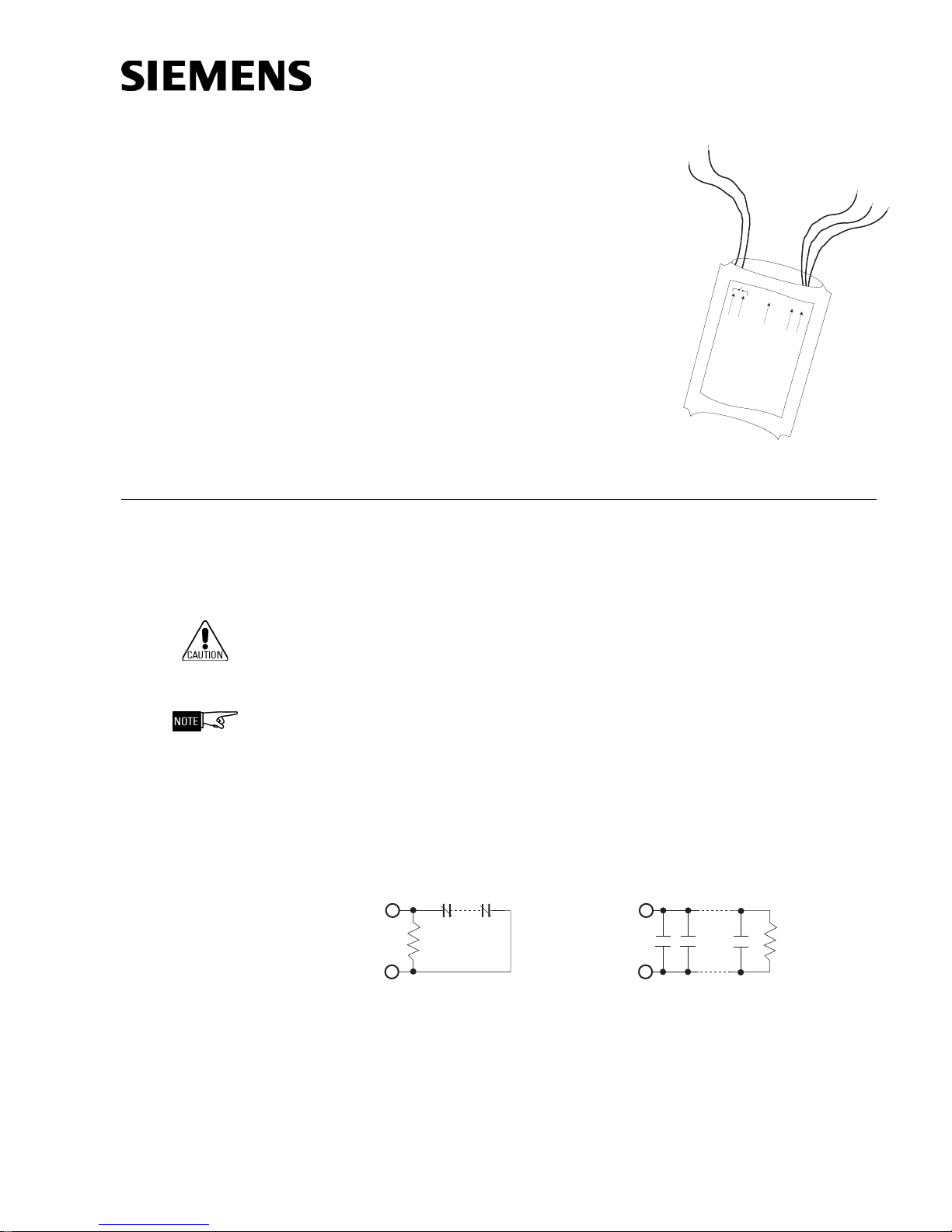
The Model HTRI-M Series Addressable Interface
Module from Siemens Industry, Inc. interfaces
direct shorting devices to the DLC loop circuit of
the FireFinder-XLS System or the FS-DLC loop of
the FS-250 System. It is also approved for 1076,
Proprietary Burglary.
The HTRI-M can monitor a normally open or closed
dry contact and it can report the status of the contact.
Figure 1
HTRI-M Module
PROGRAMMING Refer to Figure 1 to locate the red and black DLC/FS-DLC loop circuit wires of the HTRI-M.
Connect the Addressable Loop Driver circuit wires of the HTRI-M to the Model DPU
Programmer/Tester. Use the cable provided with the Programmer/Tester and the 2
alligator clip to banana plug adapters provided.
To Prevent Damage To The DPU:
DO NOT connect a HTRI-M to the DPU until all field wiring is removed from the
red and black DLC/FS-DLC loop circuit wires of the HTRI-M.
Connection from the DPU to the HTRI-M is not polarity sensitive. Refer to Figure
3 for the proper connections to the control panel.
(Refer to Figure 2.) Follow the instructions in the DPU Programmer/Tester Manual
(P/N 315-033260) to program the desired address into HTRI-M.
Record the device address on the label located on the HTRI-M. The HTRI-M can now
be installed and wired to the system.
PROGRAMMABLE
(SEE NOTE 4)
NORMALLY OPEN SWITCHES
PROGRAMMABLENORMALLY CLOSED SWITCHES
(SEE NOTES 2, 3 AND 5)
P/N 315-049480-4
Figure 2
Wiring Switches
ENDOFLINE
RESISTOR
470 OHMS,
1/4W
NOTES:
1. There can be any number of normally closed or normally open switches.
2. The end of line resistor must be located at the last switch.
3. Do not wire a normally closed switch across the end of line resistor.
4. Only for use with security and status applications.
5. Do not use N.O. switches for security applications.
Siemens Siemens
Siemens
Siemens Siemens
Building Building
Building
Building Building
TT
ecec
T
ec
TT
ecec
ENDOFLINE
RESISTOR
470 OHMS,
1/4W
IndustryIndustry
Industry
IndustryIndustry
hnologies Dihnologies Di
hnologies Di
hnologies Dihnologies Di
,,
Inc. Inc.
,
Inc.
,,
Inc. Inc.
visionvision
vision
visionvision
WIRING (Refer to Figure 3.) Refer to the wiring diagram and wire the addressable interface
module accordingly.
Recommended wire size: 18 AWG minimum
14 AWG maximum
SUPERVISED SWITCH
(SEE NOTES 1 AND 2)
LINE 2
LINE 1
LINE 2
LINE 1
470 OHM, ¼W
END OF LINE DEVICE
(SEE NOTE 2)
GROUND
(SEE NOTE 5)
FROM FIREFINDER-XLS / FS-250
CONTROL PANELADDRESSABLE
LOOP DRIVER CIRCUIT OR FROM
PREVIOUS ADDRESSABLE DEVICE
TO NEXT
ADDRESSABLE DEVICE
HTRI-M
ORANGE
ORANGE
GREEN
BLACK
RED
Figure 3
Installing the HTRI-M Wiring
NOTES:
1. All supervised switches must be held closed and/or open for at least a quarter of a second to guarantee detection.
2. End of line device: 470 ohm, 1/4W resistor, P/N 140-820164. For Canadian applications, use Model EL-33 with 470 ohm, 1/4W resistor.
3. HTRI-M is polarity insensitive. Line 1 and Line 2 can be either line of the loop.
4. The supervised switches have the following ratings:
Voltage maximum: 27 VDC
Current maximum: 6mA during polling
Contact resistance maximum: 10 ohms
Maximum cable length: 200 feet (18 AWG) C
: 0.02uF C
Line to line
Max line size: 14 AWG Min line size: 18 AWG
Line to shield
: 0.04uF
Ground shield ONLY at the specified location on the Control Panel.
EOL device must be a 470 ohm, 1/4 W resistor.
When replacing an existing HTRI on a device loop,
you must also replace the EOL resistor if it is not
470 ohms, 1/4W.
5. The green wire must be connected to earth ground.
a. Use wire nuts to pass the shield wire through the electrical box with NO connection to the device green wire.
b. Use shielded wire to connect the switch wiring.
c. Tie the switch wiring shield to earth ground.
6. For proprietary burglary application:
a. Use a TSW-1/2 tamper switch to monitor the main enclosure.
b. Monitor each HTRI-M related to this application continuously by using a listed motion detector (to prevent tampering).
7. In supervisory: HTRI-M draws 1.3mA
8. All circuits are power limited.
9. Positive and negative ground fault detected at <25K ohms for orange terminals.
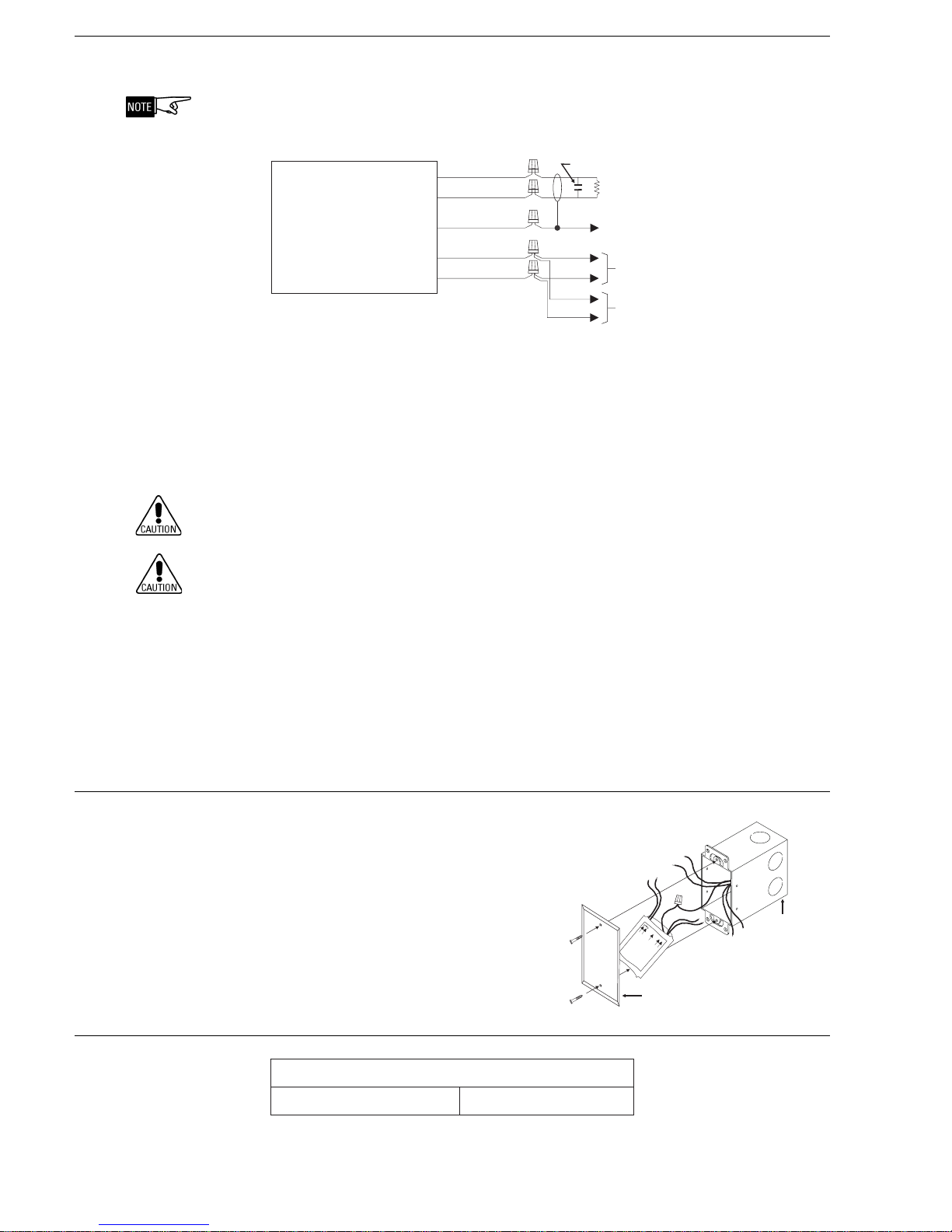
MOUNTING The Model HTRI-M mounts directly into a single gang switchbox
(user supplied)
Connect the appropriate wires using wire
nuts.Tuck the HTRI-M module inside the
electrical box and dress the wiring as required. (See Figure 4.)
HTRI-M
ORG BLKGRNORG RED
ALLCONNECTIONSAREPOWER LIMITED
EARTH
GND
LINE
2
LIN
E
1
DO NOT
USE REAR
CONDUIT
ENTRY
SINGLEGANG
SWITCHBOX
(USER SUPPLIED)
ELECTRICAL RATINGS
Siemens Industry, Inc.
Building Technologies Division
Florham Park, NJ
Siemens Building Technologies, Ltd.
Fire Safety & Security Products
2 Kenview Boulevard
Brampton, Ontario
L6T 5E4 Canada
Figure 4
Mounting the HTRI-M
pooLCLD-SF/CLD
tnerruC.xaMAm3.1
BLANK SINGLEGANG
SWITCHPLATE
(USER SUPPLIED)
P/N 315-049480-4
 Loading...