

Page 1

SINUMERIK
SINUMERIK 840D sl
Operator panel front: OP 012
Valid for:
Control system
SINUMERIK 840D sl/840DE sl
General information and
networking
1
Manual
Description
Operator control and display
elements
Interfaces
Installation
Technical data
Spare parts
2
3
4
5
6
7
09/2016
A5E36371591B
Page 2
Legal information
Warning notice system
This manual contains notices you have to observe in order to ensure your personal safety, as well as to prevent
damage to property. The notices referring to your personal safety are highlighted in the manual by a safety alert
symbol, notices referring only to property damage have no safety alert symbol. These notices shown below are
graded according to the degree of danger.
DANGER
indicates that death or severe personal injury will result if proper precautions are not taken.
WARNING
indicates that death or severe personal injury may result if proper precautions are not taken.
CAUTION
indicates that minor personal injury can result if proper precautions are not taken.
NOTICE
indicates that property damage can result if proper precautions are not taken.
If more than one degree of danger is present, the warning notice representing the highest degree of danger will be
used. A notice warning of injury to persons with a safety alert symbol may also include a warning relating to property
damage.
Qualified Personnel
The product/system described in this documentation may be operated only by personnel qualified for the specific
task in accordance with the relevant documentation, in particular its warning notices and safety instructions. Qualified
personnel are those who, based on their training and experience, are capable of identifying risks and avoiding
potential hazards when working with these products/systems.
Proper use of Siemens products
Note the following:
WARNING
Siemens products may only be used for the applications described in the catalog and in the relevant technical
documentation. If products and components from other manufacturers are used, these must be recommended or
approved by Siemens. Proper transport, storage, installation, assembly, commissioning, operation and
maintenance are required to ensure that the products operate safely and without any problems. The permissible
ambient conditions must be complied with. The information in the relevant documentation must be observed.
Trademarks
All names identified by ® are registered trademarks of Siemens AG. The remaining trademarks in this publication
may be trademarks whose use by third parties for their own purposes could violate the rights of the owner.
Disclaimer of Liability
We have reviewed the contents of this publication to ensure consistency with the hardware and software described.
Since variance cannot be precluded entirely, we cannot guarantee full consistency. However, the information in
this publication is reviewed regularly and any necessary corrections are included in subsequent editions.
Siemens AG
Division Digital Factory
Postfach 48 48
90026 NÜRNBERG
GERMANY
A5E36371591B
Ⓟ 09/2016 Subject to change
Copyright © Siemens AG 2007 - 2016.
All rights reserved
Page 3

Table of contents
1 General information and networking.............................................................................................................5
1.1 Fundamental safety instructions..............................................................................................5
1.1.1 General safety instructions.......................................................................................................5
1.1.2 Handling electrostatic sensitive devices (ESD)........................................................................8
1.1.3 Industrial security.....................................................................................................................8
1.1.4 Residual risks of power drive systems...................................................................................10
1.2 Application planning...............................................................................................................11
1.2.1 Secondary electrical conditions..............................................................................................11
1.2.1.1 Power supply..........................................................................................................................11
1.2.1.2 Grounding concept.................................................................................................................12
1.2.1.3 EMC compatibility..................................................................................................................12
1.2.2 Ambient climatic and mechanical conditions..........................................................................14
1.2.2.1 Transport and storage conditions...........................................................................................14
1.2.2.2 Operating conditions..............................................................................................................16
1.2.2.3 Cooling...................................................................................................................................17
1.2.3 Standards and approvals.......................................................................................................20
1.2.4 Recycling and disposal..........................................................................................................21
1.3 Connecting.............................................................................................................................22
1.3.1 Pin assignment of the interfaces............................................................................................22
1.3.2 Handling membrane connectors............................................................................................36
1.4 Networking.............................................................................................................................36
1.4.1 System settings......................................................................................................................36
1.4.1.1 Settings for SINUMERIK solution line....................................................................................36
1.4.1.2 System boot with system network..........................................................................................38
1.4.1.3 Thin Client Unit (TCU)............................................................................................................39
1.4.1.4 Factory default settings..........................................................................................................40
1.4.2 Commissioning TCU..............................................................................................................42
1.4.2.1 Using the TCU's main menu..................................................................................................42
1.4.2.2 Using additional TCU menus.................................................................................................45
1.4.2.3 How to register a TCU on the system network.......................................................................55
1.4.2.4 How to calibrate a touch panel...............................................................................................59
1.4.2.5 Connecting-up the SIMATIC Thin Client Touch Panel...........................................................61
1.4.2.6 This is how you configure the SIMATIC Thin Client Touch Panel..........................................62
1.4.2.7 Settings in the "config.ini" file.................................................................................................64
1.4.2.8 Settings in the "TCU.ini" file...................................................................................................66
1.4.2.9 Displacement mechanism for TCUs.......................................................................................72
1.4.2.10 Disable switchover between TCU via PLC.............................................................................74
1.4.2.11 Example: How to select the behavior of the TCUs during boot up.........................................76
1.4.3 Network configuration............................................................................................................77
1.4.3.1 Permissible network topologies..............................................................................................77
1.4.3.2 Networks without connection to the company network..........................................................78
1.4.3.3 Networks with NCU connection to the company network......................................................80
1.4.3.4 Example: Configuring a VNC connection to a PC..................................................................83
1.4.3.5 Application example...............................................................................................................85
Operator panel front: OP 012
Manual, 09/2016, A5E36371591B 3
Page 4

Table of contents
1.4.4 Service and diagnostics.........................................................................................................87
1.4.4.1 Booting of the TCU ...............................................................................................................87
2 Description..................................................................................................................................................89
3 Operator control and display elements.......................................................................................................91
3.1 View.......................................................................................................................................91
3.2 Keyboard................................................................................................................................92
3.3 Screen saver..........................................................................................................................93
3.4 Touchpad mouse...................................................................................................................94
4 Interfaces....................................................................................................................................................95
5 Installation..................................................................................................................................................97
5.1 Preparation for mounting........................................................................................................97
5.2 Assembling an OP 012 and a PCU........................................................................................98
5.3 Mounting on the mounting wall............................................................................................101
5.4 Softkey labeling....................................................................................................................102
6 Technical data..........................................................................................................................................103
7 Spare parts...............................................................................................................................................105
7.1 Overview..............................................................................................................................105
7.2 Replacement........................................................................................................................106
Index.........................................................................................................................................................109
Operator panel front: OP 012
4 Manual, 09/2016, A5E36371591B
Page 5
General information and networking
1.1 Fundamental safety instructions
1.1.1 General safety instructions
DANGER
Danger to life due to live parts and other energy sources
Death or serious injury can result when live parts are touched.
● Only work on electrical devices when you are qualified for this job.
● Always observe the country-specific safety rules.
Generally, six steps apply when establishing safety:
1. Prepare for shutdown and notify all those who will be affected by the procedure.
2. Disconnect the machine from the supply.
– Switch off the machine.
– Wait until the discharge time specified on the warning labels has elapsed.
– Check that it really is in a no-voltage condition, from phase conductor to phase
conductor and phase conductor to protective conductor.
– Check whether the existing auxiliary supply circuits are de-energized.
– Ensure that the motors cannot move.
3. Identify all other dangerous energy sources, e.g. compressed air, hydraulic systems, or
water.
4. Isolate or neutralize all hazardous energy sources by closing switches, grounding or shortcircuiting or closing valves, for example.
5. Secure the energy sources against switching on again.
6. Ensure that the correct machine is completely interlocked.
1
After you have completed the work, restore the operational readiness in the inverse sequence.
WARNING
Danger to life through a hazardous voltage when connecting an unsuitable power supply
Touching live components can result in death or severe injury.
● Only use power supplies that provide SELV (Safety Extra Low Voltage) or PELV(Protective Extra Low Voltage) output voltages for all connections and terminals of the
electronics modules.
Operator panel front: OP 012
Manual, 09/2016, A5E36371591B 5
Page 6
General information and networking
1.1 Fundamental safety instructions
WARNING
Danger to life when live parts are touched on damaged devices
Improper handling of devices can cause damage.
For damaged devices, hazardous voltages can be present at the enclosure or at exposed
components; if touched, this can result in death or severe injury.
● Ensure compliance with the limit values specified in the technical data during transport,
storage and operation.
● Do not use any damaged devices.
WARNING
Danger to life through electric shock due to unconnected cable shields
Hazardous touch voltages can occur through capacitive cross-coupling due to unconnected
cable shields.
● As a minimum, connect cable shields and the cores of cables that are not used at one end
at the grounded housing potential.
WARNING
Danger to life due to electric shock when not grounded
For missing or incorrectly implemented protective conductor connection for devices with
protection class I, high voltages can be present at open, exposed parts, which when touched,
can result in death or severe injury.
● Ground the device in compliance with the applicable regulations.
WARNING
Danger to life due to fire spreading if housing is inadequate
Fire and smoke development can cause severe personal injury or material damage.
● Install devices without a protective housing in a metal control cabinet (or protect the device
by another equivalent measure) in such a way that contact with fire is prevented.
● Ensure that smoke can only escape via controlled and monitored paths.
Operator panel front: OP 012
6 Manual, 09/2016, A5E36371591B
Page 7

General information and networking
1.1 Fundamental safety instructions
WARNING
Danger to life through unexpected movement of machines when using mobile wireless
devices or mobile phones
Using mobile wireless devices or mobile phones with a transmit power > 1 W closer than
approx. 2 m to the components may cause the devices to malfunction, influence the functional
safety of machines therefore putting people at risk or causing material damage.
● Switch the wireless devices or mobile phones off in the immediate vicinity of the
components.
WARNING
Danger to life due to fire if overheating occurs because of insufficient ventilation clearances
Inadequate ventilation clearances can cause overheating of components with subsequent
fire and smoke. This can cause severe injury or even death. This can also result in increased
downtime and reduced service lives for devices/systems.
● Ensure compliance with the specified minimum clearance as ventilation clearance for the
respective component.
WARNING
Danger to life when safety functions are inactive
Safety functions that are inactive or that have not been adjusted accordingly can cause
operational faults on machines that could lead to serious injury or death.
● Observe the information in the appropriate product documentation before commissioning.
● Carry out a safety inspection for functions relevant to safety on the entire system, including
all safety-related components.
● Ensure that the safety functions used in your drives and automation tasks are adjusted
and activated through appropriate parameterizing.
● Perform a function test.
● Only put your plant into live operation once you have guaranteed that the functions relevant
to safety are running correctly.
Note
Important safety notices for Safety Integrated functions
If you want to use Safety Integrated functions, you must observe the safety notices in the Safety
Integrated manuals.
Operator panel front: OP 012
Manual, 09/2016, A5E36371591B 7
Page 8

General information and networking
1.1 Fundamental safety instructions
1.1.2 Handling electrostatic sensitive devices (ESD)
Electrostatic sensitive devices (ESD) are individual components, integrated circuits, modules
or devices that may be damaged by either electric fields or electrostatic discharge.
NOTICE
Damage through electric fields or electrostatic discharge
Electric fields or electrostatic discharge can cause malfunctions through damaged individual
components, integrated circuits, modules or devices.
● Only pack, store, transport and send electronic components, modules or devices in their
original packaging or in other suitable materials, e.g conductive foam rubber of aluminum
foil.
● Only touch components, modules and devices when you are grounded by one of the
following methods:
– Wearing an ESD wrist strap
– Wearing ESD shoes or ESD grounding straps in ESD areas with conductive flooring
● Only place electronic components, modules or devices on conductive surfaces (table with
ESD surface, conductive ESD foam, ESD packaging, ESD transport container).
1.1.3 Industrial security
Note
Industrial security
Siemens provides products and solutions with industrial security functions that support the
secure operation of plants, solutions, machines, equipment and/or networks. They are
important components in a holistic industrial security concept. With this in mind, Siemens’
products and solutions undergo continuous development. Siemens recommends strongly that
you regularly check for product updates.
For the secure operation of Siemens products and solutions, it is necessary to take suitable
preventive action (e.g. cell protection concept) and integrate each component into a holistic,
state-of-the-art industrial security concept. Third-party products that may be in use should also
be considered. For more information about industrial security, visit this address (http://
www.siemens.com/industrialsecurity).
To stay informed about product updates as they occur, sign up for a product-specific
newsletter. For more information, visit this address (http://support.automation.siemens.com).
Operator panel front: OP 012
8 Manual, 09/2016, A5E36371591B
Page 9

General information and networking
1.1 Fundamental safety instructions
WARNING
Danger as a result of unsafe operating states resulting from software manipulation
Software manipulation (e.g. by viruses, Trojan horses, malware, worms) can cause unsafe
operating states to develop in your installation which can result in death, severe injuries and/
or material damage.
● Keep the software up to date.
You will find relevant information and newsletters at this address (http://
support.automation.siemens.com).
● Incorporate the automation and drive components into a holistic, state-of-the-art industrial
security concept for the installation or machine.
You will find further information at this address (http://www.siemens.com/
industrialsecurity).
● Make sure that you include all installed products into the holistic industrial security concept.
WARNING
Danger to life due to software manipulation when using exchangeable storage media
Storing files onto exchangeable storage media amounts to an increased risk of infection, e.g.
with viruses and malware. As a result of incorrect parameterization, machines can
malfunction, which in turn can lead to injuries or death.
● Protect files stored on exchangeable storage media from malicious software by taking
suitable protection measures, e.g. virus scanners.
Operator panel front: OP 012
Manual, 09/2016, A5E36371591B 9
Page 10

General information and networking
1.1 Fundamental safety instructions
1.1.4 Residual risks of power drive systems
When assessing the machine- or system-related risk in accordance with the respective local
regulations (e.g., EC Machinery Directive), the machine manufacturer or system installer must
take into account the following residual risks emanating from the control and drive components
of a drive system:
1. Unintentional movements of driven machine or system components during commissioning,
operation, maintenance, and repairs caused by, for example,
– Hardware and/or software errors in the sensors, control system, actuators, and cables
and connections
– Response times of the control system and of the drive
– Operation and/or environmental conditions outside the specification
– Condensation/conductive contamination
– Parameterization, programming, cabling, and installation errors
– Use of wireless devices/mobile phones in the immediate vicinity of electronic
components
– External influences/damage
– X-ray, ionizing radiation and cosmic radiation
2. Unusually high temperatures, including open flames, as well as emissions of light, noise,
particles, gases, etc., can occur inside and outside the components under fault conditions
caused by, for example:
– Component failure
– Software errors
– Operation and/or environmental conditions outside the specification
– External influences/damage
3. Hazardous shock voltages caused by, for example:
– Component failure
– Influence during electrostatic charging
– Induction of voltages in moving motors
– Operation and/or environmental conditions outside the specification
– Condensation/conductive contamination
– External influences/damage
4. Electrical, magnetic and electromagnetic fields generated in operation that can pose a risk
to people with a pacemaker, implants or metal replacement joints, etc., if they are too close
5. Release of environmental pollutants or emissions as a result of improper operation of the
system and/or failure to dispose of components safely and correctly
For more information about the residual risks of the drive system components, see the relevant
sections in the technical user documentation.
Operator panel front: OP 012
10 Manual, 09/2016, A5E36371591B
Page 11

1.2 Application planning
1.2.1 Secondary electrical conditions
1.2.1.1 Power supply
Requirements for DC power supplies
DANGER
Danger of death caused by unsafe power supply
The DC power supply must be implemented as a circuit of Category PELV/DVC A according
to EN 61800-5-1.
WARNING
General information and networking
1.2 Application planning
Inadequately fused supply cables can be life-threatening
In the case of supply lines > 10 m, protectors must be installed at the device input in order to
protect against lightning (surge).
The DC power supply must be connected to the ground/shield of the NC for EMC and/or
functional reasons. For EMC reasons, this connection should only be made at one point. As
a rule, the connection is provided as standard in the S7-300 I/Os. In exceptional
circumstances when this is not the case, the ground connection should be made on the
grounding rail of the NC cabinet (also refer to /EMC/EMC Installation Guide.)
Table 1-1 Requirements of the DC power supply
Rated voltage According to EN 61131-2
Voltage range (mean value)
Voltage ripple, peak/peak
Powering up time when switched
on
Non-periodic overvoltages
Period of overvoltage
Recover time
Events per hour
Transient voltage interruptions Downtime
Recovery time
Events per hour
24 VDC
20.4 VDC to 28.8 VDC
5% (unsmoothed 6-pulse recti‐
fication)
any
≤ 35 V
≤ 500 ms
≥ 50 s
≤ 10
≤ 3 ms
≥ 10 s
≤ 10
Operator panel front: OP 012
Manual, 09/2016, A5E36371591B 11
Page 12

General information and networking
1.2 Application planning
1.2.1.2 Grounding concept
Components
The SINUMERIK 840D sl system consists of a number of individual components which have
been designed so that the system complies with the appropriate EMC and safety standards.
The individual system components are:
● Numerical Control Unit (NCU)
● Machine Control Panel (MCP), Machine Pushbutton Panel (MPP)
● Keyboard
● Operator panels (operator panel front + TCU/PCU)
● Distributor box and handheld unit
● S7-300 I/O with IM 153 interface module
Grounding measures
The individual modules are attached to a metal cabinet panel. Insulating paints on the mounting
points (e.g. tension jacks) must be removed.
It is permissible to cluster the operator control components regarding connection/potential
bonding.
Example: The control panel on the swivel arm.
It is sufficient in this instance to connect the ground connections of, for example, the PCU,
TCU, and operator panel front using a cable and to route a shared grounding conductor to the
central ground connection in the control cabinet.
Additional references
EMC Design Guidelines
1.2.1.3 EMC compatibility
In addition to the protective grounding of system components, special precautions must be
taken to guarantee safe, trouble-free operation of the system. These measures include
shielded signal lines, special equipotential bonding connections, and isolation and shielding
measures.
Shielded signal cables
● For safe and fault-free operation of the system, the specified cables must be used.
● For digital signal transmission, the shield must have a conductive connection at both sides
of the housing.
Operator panel front: OP 012
12 Manual, 09/2016, A5E36371591B
Page 13
Cable definition
Definition:
● Signal cables (example)
– Data cables (Ethernet, PROFIBUS, sensor cables, etc.)
– Digital I/Os
– Cables for safety functions (emergency stop, enabling)
● Power cables (example)
– Low-voltage supply lines (230 VAC, +24 VDC, etc.)
– Motor cables
Rules for routing cables
In order to achieve the greatest possible EMC compatibility for the complete system (control,
power unit, machine), the following EMC measures must be carefully observed:
● If necessary, signal and power cables may cross one another (if possible at an angle of
90°), but must never be laid close or parallel to one another.
General information and networking
1.2 Application planning
● Only use cables approved by SIEMENS for the signal lines from and to the Control Unit.
● Signal cables must not be routed close to strong external magnetic fields (e.g. motors and
transformers).
● If signal lines cannot be routed a sufficient distance away from other cables, they must be
installed in grounded cable ducts (metal).
● The operator panel fronts, MCPs, MPPs, and full keyboards must be installed in metallically
enclosed EMC-compatible housings.
Note
For further information on interference suppression measures and the connection of
shielded cables, please refer to the EMC Installation Guide.
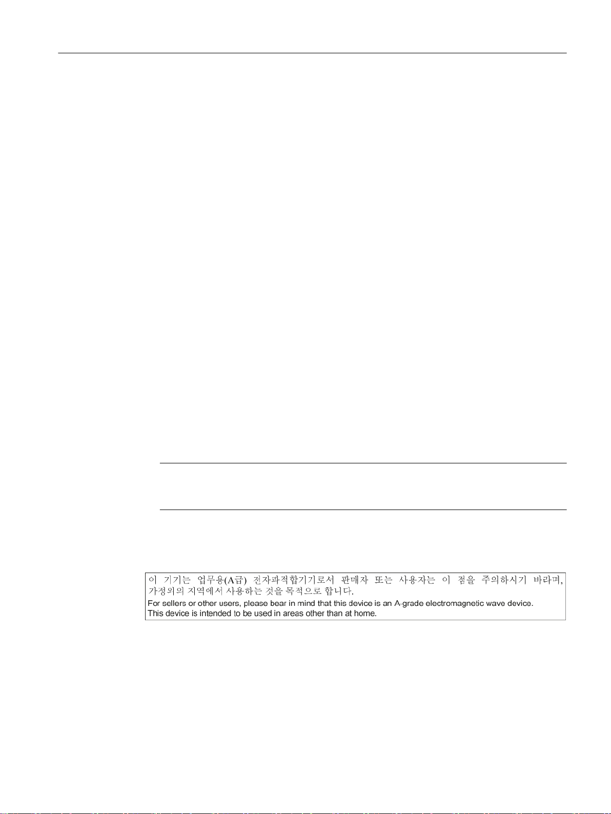
EMC limit values in South Korea
The EMC limit values to be complied with for South Korea correspond to the limit values of the
EMC product standard for variable-speed electric drives EN 61800-3, Category C2, or limit
value class A, Group 1 according to EN 55011. By applying suitable supplementary measures,
the limit values according to Category C2 or according to limit value class A, Group 1, are
maintained. Further, additional measures may be required, for instance, using an additional
radio interference suppression filter (EMC filter).
The measures for EMC-compliant design of the system are described in detail in this manual
respectively in the Installation Guideline EMC.
Operator panel front: OP 012
Manual, 09/2016, A5E36371591B 13
Page 14

General information and networking
1.2 Application planning
Please note that the final statement on compliance with the standard is given by the respective
label attached to the individual unit.
1.2.2 Ambient climatic and mechanical conditions
1.2.2.1 Transport and storage conditions
The components of the SINUMERIK 840D sl system exceed the requirements according to
EN 61800‑2 with regard to shipping and storage conditions.
The following data applies under the following conditions:
● Long-term storage in the transport and product packaging:
At weather-protected locations that have continuous contact with outside air through
openings.
● Transport in the transport packaging:
– In unventilated containers under conditions not protected from weather effects.
– In the “cold" in accordance with outside air.
– Air transport in the air-conditioned cargo hold.
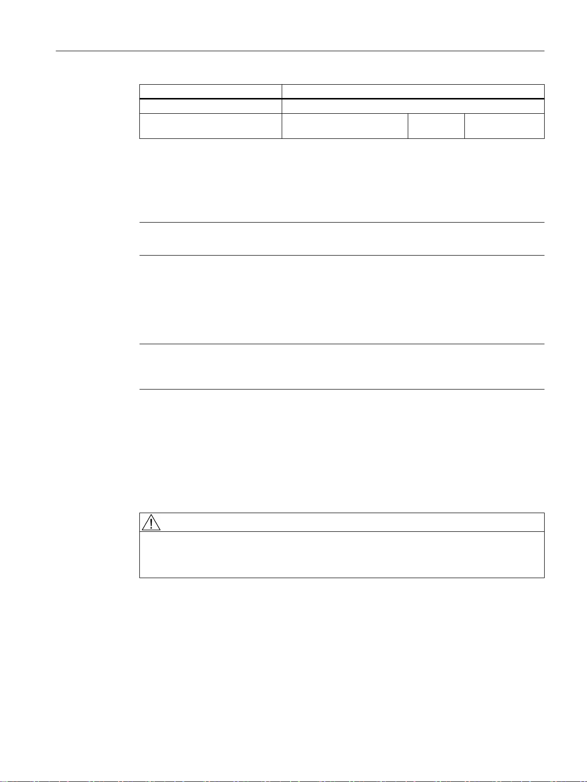
Table 1-2 Ambient conditions during storage and transport
Type of condition Permissible range/class
Transport Storage
Classification EN 60721-3-2 EN 60721-3-1
Climate class 2K4 1K4
Ambient temperature
Biological environmental condi‐
tions
Chemically active environmental
conditions
Maximum permissible tempera‐
ture change
Relative humidity (without conden‐
sation)
Precipitation, rain 6 mm/min
Water other than rain 1 m/s and wet loading surfa‐
1)
-40° C ... +70° C -25° C ... +55° C
2)
2B1
3)
2C2
Direct interaction in air/air:
1B1
1C2
30 k/h
2)
3)
-40°/+30° C at 95% relative
humidity
5 to 95%
ces
2)
Not permis‐
4)
Not permissible
5)
sible
1 m/s and wet
loading surfaces
4)
Operator panel front: OP 012
14 Manual, 09/2016, A5E36371591B
Page 15
Type of condition Permissible range/class
Height Max. 4,000 m above sea level
Condensation, splash water,
icing, salt spray
1)
Transport and storage of operator panel fronts and diskette drives: -20° C to +55° C.
2)
Mold growth, slime, rodents, termites and other animal vermin are not permissible.
3)
In marine- and weather-resistant transport packaging (container).
4)
For storage in the transport packaging.
5)
For storage in the product packaging.
Note
Remove the transport protective foil and packaging material before installing the components.
Shipping backup batteries
Backup batteries must only be shipped in the original packaging. No special authorization is
required to ship backup batteries. The lithium content is approximately 300 mg.
General information and networking
1.2 Application planning
Permissible Not permis‐
sible
5)
Permissible
4)
Note
The backup battery is classified as a hazardous substance, Class 9 in accordance with the
relevant air-freight transportation regulations.
Storage of backup batteries
Always store backup batteries in a cool and dry place. The batteries have a maximum shelf
life of 10 years.
Rules for handling backup batteries
WARNING
Incorrect handling of backup batteries can lead to a risk of ignition, explosion and combustion
The stipulations of DIN EN 60086-4, in particular regarding avoidance of mechanical or
electrical tampering of any kind, must be complied with.
● Do not open a battery. Replace a faulty battery only with the same type.
● Obtain replacement batteries only from Siemens.
● Always try to return low batteries to the manufacturer or deliver these to a registered
recycling company.
Operator panel front: OP 012
Manual, 09/2016, A5E36371591B 15
Page 16

General information and networking
1.2 Application planning
1.2.2.2 Operating conditions
The components of the SINUMERIK 840D sl system are intended for a weatherproof, fixed
location. The documented
environmental conditions apply to the climate in the immediate vicinity of the units and to the
entry of the cooling air. They exceed the requirements according to EN 60204-1, EN 61800-2,
EN 61131-2 and IEC 62477-1.
NOTICE
Damage to components by coolants and lubricants
The SINUMERIK operator components have been designed for industrial use, particularly on
machine tools and production machines. This also takes into account the use of commercially
available coolants and lubricants. The use of aggressive compounds and additives can
damage components and result in their failure.
Contact between the operator components and coolants and lubricants should be avoided
as far as possible, as resistance to all coolants and lubricants cannot be guaranteed.
Table 1-3 Ambient conditions for operation
Environmental conditions Application areas Remarks
Climatic environmental conditions
Climate class Better than class 3K3 According to EN 60721‑3-3
Permissible ambient tempera‐
ture when installed vertically
Relative humidity (without con‐
densation)
Condensation, formation of ice Not permissible
Dripping water, spray, splash
water, jet-water according to de‐
gree of protection
Max. installation altitude Up to 4000 m (13123 ft) above sea level
Air pressure 620 hPa ... 1060 hPa According to altitude range 0 m to 4000 m
0 ... 45 °C (32 ... 113
°F), up to 2000 m
(6562 ft) above sea
level
0 ... 55 °C (32 ... 131
°F), up to 2000 m
(6562 ft) above sea
level
5 ... 55 °C (41 ... 131
°F), up to 2000 m
(6562 ft) above sea
level
Above an altitude of 2000 m (6562 ft), the max. ambient temperature
decreases by 7 °C (44.6 °F) for every 1000 m (3281 ft) increase in
altitude
5% to 95% (60% when corrosive gases and/or dusts are present)
Not permissible All components, except ...
Permissible For handheld units, front side of operator
Except PCU50.5;
front-side for OP, MCP/MPP and CNC
standard keyboards KB.
All, rear-side for OP, MCP/MPP and CNC
standard keyboards KB.
For PCU50.5
and machine control panels (MCP and
MPP), front side of the keyboards KB 310
and KB 483C
(0 ft to 13123 ft) above sea level
Operator panel front: OP 012
16 Manual, 09/2016, A5E36371591B
Page 17

General information and networking
1.2 Application planning
Environmental conditions Application areas Remarks
Biological, chemical and mechanical influences, pollutants
Biological environmental conditions Class 3B1 according to EN 60 721-3-3:
Mold, mold growth, slime, rodents, termite
and other animal vermin are not permissible.
Chemically active environmental conditions Class 3C1 according to EN 60721‑3‑3
Mechanically active environmental conditions Class 3S1 according to EN 60721‑3‑3:
Conductive dust not permissible.
Classification of the mechanical
environment
Degree of contamination 2
EMC conducted / radiation Class C3 according to EN 61800-3
3M3 for components on the machine
3M1/3M2 for components in the control cab‐
inet
Note
The user must consider radio interference for the complete system. Particular attention should
be paid to cabling. Please contact your sales representative for assistance and support.
If compliance with limit value class C2 is required, please contact your local sales
representative.
1.2.2.3 Cooling
To calculate the heat dissipation, the total power loss P
in a housing must be taken into account.
Total power loss P
Convection surface area A [m2]:
The surface areas of the front and bottom sides are not included in the convection surface
area calculation.
Note
A recommended value for the power loss of the operator control components is contained in
the "Technical data" section of the associated component (see "Power consumption").
Means of heat dissipation
Heat dissipation can take place as follows:
● Heat dissipation by natural convection
● Heat dissipation by natural convection and internal air turbulence
● Heat dissipation by open-circuit cooling
● Heat dissipation by open-circuit ventilation
= PV1 + PV2 + PV3 +... [W]
Vtotal
of all heat-generating components
Vtotal
Operator panel front: OP 012
Manual, 09/2016, A5E36371591B 17
Page 18
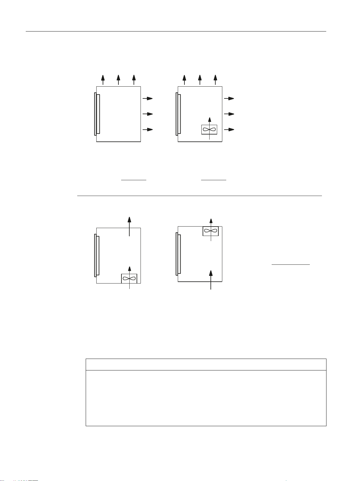
+HDWGLVVLSDWLRQ
XVLQJRSHQFLUFXLWYHQWLODWLRQ
2SHUDWRU
SDQHOIURQW
+HDWGLVVLSDWLRQ
XVLQJRSHQFLUFXLWYHQWLODWLRQ
7KHUHTXLUHGYROXPHWULF
IORZIRUGLVVLSDWLQJWKHKHDW
ORVVLVFDOFXODWHGXVLQJ
DSSUR[LPDWLRQVIURP
2SHUDWRU
SDQHOIURQW
+HDWGLVVLSDWLRQ
XVLQJQDWXUDOFRQYHQWLRQDQG
LQWHUQDOWXUEXOHQFH
+HDWGLVVLSDWLRQ
XVLQJQDWXUDOFRQYHFWLRQ
7KHUHTXLUHGIUHHFRQYHFWLRQVXUIDFH$>P@RIWKH
URRPWREHFRQYHUWHGVWHHORUDOXPLQXPVKHHWLQJPPWKLFNQHVVLVFDOFXODWHGEDVHGRQ
DWHPSHUDWXUHGLIIHUHQFH77 ෙ7ุ.DSSUR[LPDWHGIURP
YROXPHWULFIORZRIWKHIDQ
PK
2SHUDWRU
SDQHOIURQW
2SHUDWRU
SDQHOIURQW
39
JHV
>:@
39
JHV
>:@39
JHV
>:@
7
7
˂7>.@
9>PK@
7
7
˂7>.@
$>P@
7
7
˂7>.@
$>P@
7
7
General information and networking
1.2 Application planning
Figure 1-1 Means of heat dissipation
Fan design
● The fan must be positioned to produce an optimum heat dissipation. A clearance of 10 mm
must be maintained in front of the fan.
● The inlet and outlet slots must remain free for the open-circuit ventilation.
● Air filters must be provided to maintain the permitted environmental conditions.
NOTICE
Damage to the operating components caused by temperatures that are too high or too low
Contaminated air filters impair the desired heat dissipation. For handling the air filters, pay
attention to:
● Proper handling
● Regular replacement
● Correct disposal
18 Manual, 09/2016, A5E36371591B
Operator panel front: OP 012
Page 19
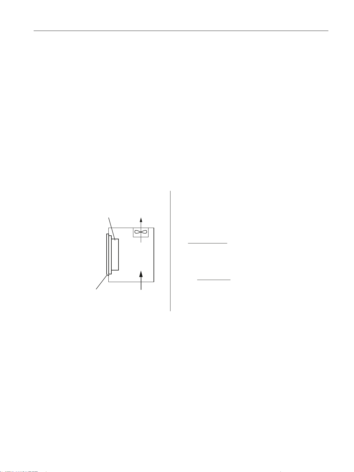
Guidelines
&DOFXODWLRQRIWKHSRZHUORVV
LQFOXGLQJLQWHUQDOSRZHUVXSSO\XQLW
([DPSOHIRUKHDWGLVVLSDWLRQZLWKRSHQFLUFXLWYHQWLODWLRQ
3&8ZLWK23
PD[:
,QWHUQDOWHPSHUDWXUH 7 r&
([WHUQDOWHPSHUDWXUH 7 r&
9 >PK@
39
JHV
>:@
39
JHV
:
˂7>.@
3&8:
23:
7
7
ය˂7 .
3&8
23
General information and networking
1.2 Application planning
If the convection area A [m2] does not suffice for the "heat dissipation using natural convection",
then use:
● "Heat dissipation using natural convection and internal turbulence" for hot spots and heat
concentrations in housings subject to space constraints. The total power loss P
Ltot
for
thermally critical applications can be determined as follows:
– Current measurement for a 24 V supply voltage
– Power loss P
● Heat dissipation using open-circuit ventilation
Calculation of the volumetric flow
The power loss (thermal) dissipated by the components in an operator unit is to be dissipated
using open-circuit ventilation. The volumetric flow V required for this should be calculated at
a difference in temperature of T2 - T1 = ΔT ≥ 10K.
[W] = U (24 V) * |measured value in ampères|
Ltot
Figure 1-2 Calculating heat dissipation for PCU 50.5 with OP 019
Operator panel front: OP 012
Manual, 09/2016, A5E36371591B 19
Page 20

General information and networking
1.2 Application planning
1.2.3 Standards and approvals
Approvals
CE approval
Figure 1-3 CE marking
The operator panels and the safety-relevant accessories satisfy the requirements and
protection objectives of the following EC directives. The operator panels and the safetyrelevant accessories comply with the harmonized European standards (EN), promulgated in
the Official Journals of the European Community:
● 2004/108/EC "Electromagnetic Compatibility" (EMC directive)
● Directive 2006/42/EC of the European Parliament and Council of May 17, 2006, on
machinery, and Directive 95/16/EC (amendment)
SIBE Switzerland Certification Service
For the HT 2 and HT 8 units.
Figure 1-4 Symbol of the certifying body
HT 2
The HT 2 operator panel and the safety-relevant accessories (is identified in the "Accessories"
section for the respective devices) satisfy Category 3, PL d according to EN ISO 13849-1:2008.
The safety function Enabling device for special mode control and the emergency stop button
satisfy the following requirements:
● Category 3, PL d according to EN ISO 13849-1:2008
● Requirements of EN 60204-1:2006, when complying with the safety instructions in the
relevant chapters of this documentation
HT 8
The HT 8 operator panel and the safety-relevant accessories (is identified in the "Accessories"
section for the respective devices) satisfy Category 3, PL d according to EN ISO 13849-1:2008.
The emergency stop button meets the following requirements:
● Category 3, PL d according to EN ISO 13849-1:2008
● Requirements of EN 60204-1:2006, when complying with the safety instructions in the
relevant chapters of this documentation
Operator panel front: OP 012
20 Manual, 09/2016, A5E36371591B
Page 21

Risk assessment
General information and networking
1.2 Application planning
The safety function Enabling device for special mode control satisfies the following
requirements:
● Category 4, PL e according to EN ISO 13849-1:2008
● Requirements of EN 60204-1:2006, when complying with the safety instructions in the
relevant chapters of this documentation
Address:
NSBIV AG, SIBE Switzerland, Brünigstrasse 18, CH-6005 Lucerne
Accreditation SCESp 0046 / Notified Body 1247
Number of the prototype test certificate: No. 1416
The following standards must be used to perform the risk assessment:
● EN ISO 12100-1:2003 and EN ISO 12100-2:2003, General Design Guidelines for Machines
● EN ISO 14121-1:2007, Risk Assessment for Machinery
● EN ISO 13849-1:2008, Safety-related Parts of Machines
These considerations result in a category (B, 1, 2, 3, 4) and a performance level (PL a to e) in
accordance with EN ISO 13849-1:2008 that ultimately dictate how the safety-related parts of
the system to be monitored must be constructed.
The connection examples with different monitoring units in "Handheld units", Section: "HT 2",
Section: "Connections" → "Connection examples for acknowledgment button and Emergency
Stop button" can also be used for other operator panels and demonstrate how Category 3, PL
d according to EN ISO 13849-1:2008 can be attained with the safety-related parts of the
operator panels. Note that the overall concept of the installation must be designed with this in
mind.
1.2.4 Recycling and disposal
Products should be disposed of corresponding to the relevant national regulations.
The products described in this manual can be mostly recycled due to the fact that they contain
very few damaging substances. To recycle and dispose of your old device in an
environmentally friendly way, please contact an appropriate disposal company.
Operator panel front: OP 012
Manual, 09/2016, A5E36371591B 21
Page 22

General information and networking
1.3 Connecting
1.3 Connecting
1.3.1 Pin assignment of the interfaces
The pins of the component interfaces are assigned as specified in the tables below. Any
deviations are indicated at the relevant point.
Signal type:
I Input
O Output
B Bidirectional (inputs/outputs)
V Power supply
- Ground (reference potential) or N.C. (not connected)
Power supply interface
Serial interface COM1
Connector type: Terminal block, 3-pin plug connector
Max. cable length: 10 m
Table 1-4 Assignment of the power supply interface
Pin Name Type Meaning
1 P24 (+) - 24 VDC potential (20.4 to 28.8 VDC)
2 M24 (-)
3 SHIELD (PE) Shield potential
VI
Ground 24 V
9-pin sub-D connector
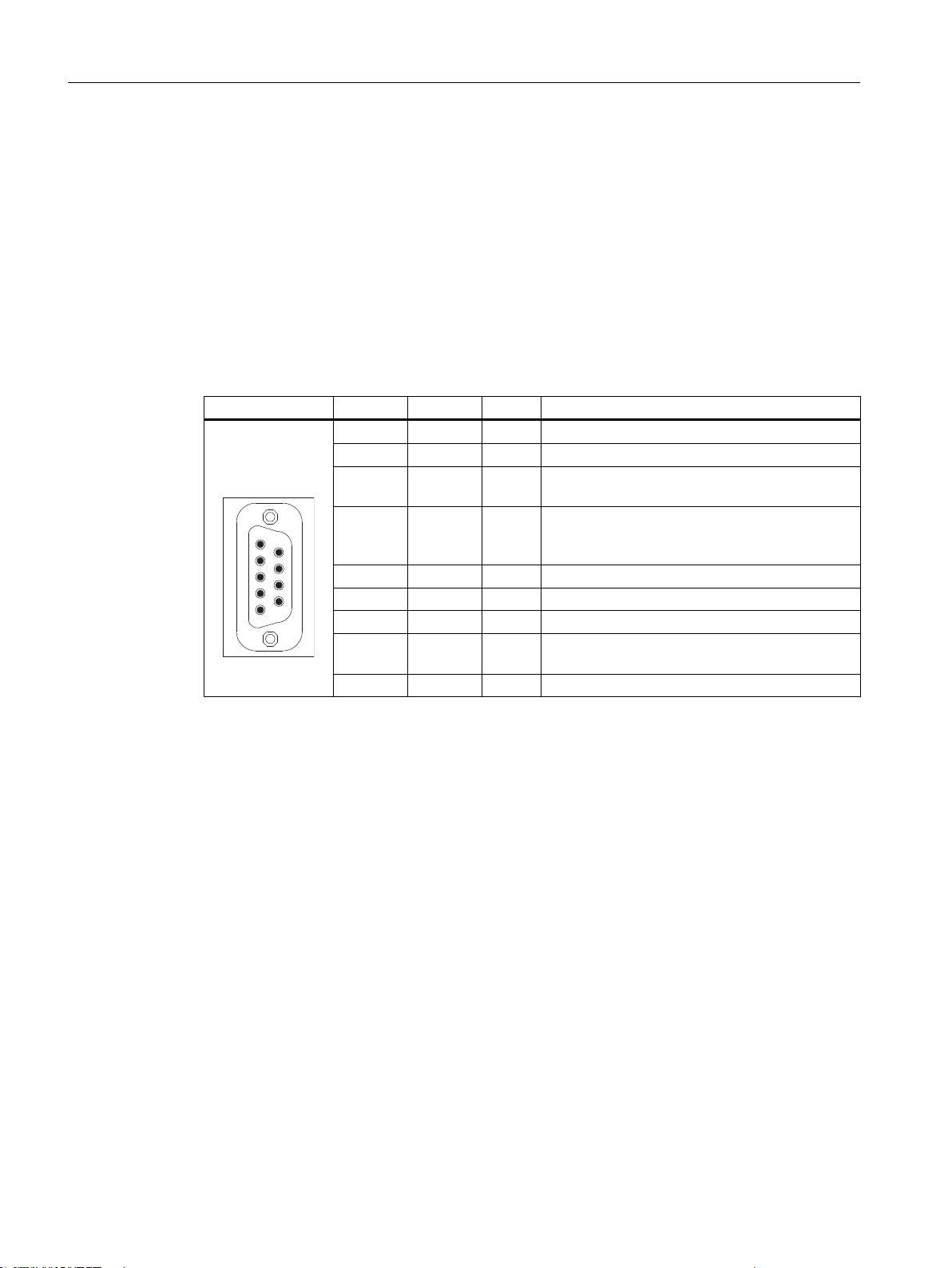
Table 1-5 Assignment of the serial interface COM1 (V.24/RS232)
Connector Pin Name Type Remark
1 DCD (M5)
2 RxD (D2) Serial receive data
3 TxD (D1)
4 DTR (S1) Data terminal ready
5 GND (E2) - Ground (reference potential)
6 DSR (M1) I Data Set Ready
7 RTS (S2) O Request To Send
8 CTS (M2)
9 RI (M3) Incoming call
Receive signal level (carrier)
I
Serial transmit data
O
Clear To Send
I
22 Manual, 09/2016, A5E36371591B
Operator panel front: OP 012
Page 23

USB interfaces
General information and networking
1.3 Connecting
The USB interfaces are implemented as sockets and comply with the generally valid standard.
The version information (1.1, 2.0 etc.), the maximum velocity (low speed, full speed, etc.) and
the socket type (A or B) are documented in the individual sections for the associated devices.
In principle, USB interfaces have the following characteristics:
● Integrated power supply up to 500 mA for each socket.
● Maximum cable length 3 m (Length including the supply cable to the hub and the connected
terminal device; only 1 hub at maximum is permitted. It should be noted that some
keyboards already have a hub.)
NOTICE
Cables that are too long can cause the screen to freeze
Observe the following restrictions for the USB front interface for connecting operator
panels to the keyboard, mouse or USB FlashDrive:
● Maximum cable length: 1.8 m
● Extension cables are not permissible
● Hot-plugging-capable devices are connected during operation and are identified
automatically.
Note
Correct identification is only guaranteed for USB I/Os that comply to 100% with the USB
specification.
Table 1-6 Assignment of the USB interface
Type A socket Type B socket Pin Name Type Remark
1 P5V_fused V + 5 V (fused)
2 Data3 Data+ Data +
4 GND V Ground (reference potential)
Data -
B
USB sticks
If you want to connect a USB stick to the USB interface, preferably use the tested SIMATIC
USB stick 16 GB for this purpose (Article No.: 6ES7648-0DC60-0AA0). Alternatively, you can
use a USB stick with any memory size. It must, however, meet the following minimum
requirements:
● File system: FAT16 or FAT32
● Partitioning: only in PC partition format (MBR)
Operator panel front: OP 012
Manual, 09/2016, A5E36371591B 23
Page 24
General information and networking
1.3 Connecting
USB sticks that deviate from these requirements have not been tested can may not be
recognized by the NCU.
PROFIBUS DP / MPI interface
Connector type: 9-pin sub-D socket
Max. data transmission rate: 12 Mbit/s
Max. cable length: 100 m
Table 1-7 Assignment of the PROFIBUS DP / MPI interface
Connector Pin Name Type Remark
1,2 N.C. - Not connected
3 LTG_B B Signal line B of MPI module
4 RTS_AS I Control signal for receive data current. Signal 1
active if directly connected control is sending.
5 M5EXT V Return line (GND) of 5 V supply. Current load
from a load of 90 mA max. connected between
P5EXT and M5EXT.
6 P5EXT V 5 V supply (current load see M5EXT)
7 N.C. - Not connected
8 LTG_A B Signal line A of MPI module
9 RTS_PG O RTS signal of MPI module; signal is "1", when
PG is sending
Shield - On connector housing
PROFIBUS DP interface
Connector type: 9-pin sub-D socket
Max. data transmission rate: 12 Mbit/s
Max. cable length: 100 m
Operator panel front: OP 012
24 Manual, 09/2016, A5E36371591B
Page 25
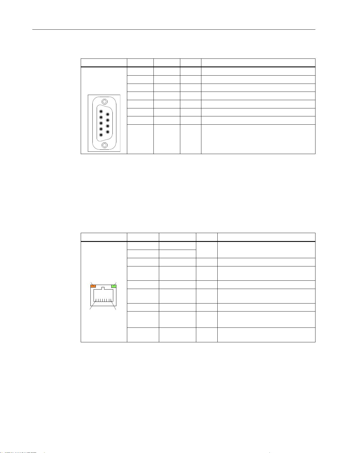
Table 1-8 Assignment of the PROFIBUS DP interface
/('/('
Connector Pin Name Type Remark
Ethernet RJ45 interface
Connector type: Standard RJ45 socket
Max. data transmission rate: 10/100/1000 Mbit/s
Max. cable length: 100 m
General information and networking
1.3 Connecting
1,2 N.C. - Not connected
3 RS_DP B RS-485 differential signal
4 RTS_DP O Request To Send
5 M5EXT V 5 V external ground
6 P5EXT V 5 V external potential
7 N.C. - Not connected
8 XRS_DP B RS-485 differential signal
9 N.C. - Not connected
Table 1-9 Assignment of the Ethernet RJ45 interface 10/100 Mbit/s
Connector Pin Name Type Remark
1 TxD+
2 TxD3 RxD+ I Receive data
4/5 GND - (terminated internally with 75 Ω; not re‐
6 RD- I Receive data
7/8 GND - (terminated internally with 75 Ω; not re‐
Shield - - On connector housing
- Green LED
(right)
- Orange LED
(left)
O Transmit data
quired for data transmission)
quired for data transmission)
- Lights up: 10 or 100 Mbit/s
Off: No or faulty connection
- Illuminated: Data exchange
Off: No data exchange
Operator panel front: OP 012
Manual, 09/2016, A5E36371591B 25
Page 26
/('/('
General information and networking
1.3 Connecting
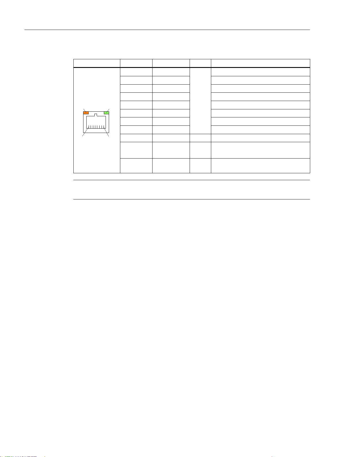
Table 1-10 Assignment of the Ethernet RJ45 interface 1000 Mbit/s
Connector Pin Name Type Remark
Note
1 DA+ B Bidirectional pair A+
2 DA- Bidirectional pair A3 DB+ Bidirectional pair B+
4 DC+ Bidirectional pair C+
5 DC- Bidirectional pair C6 DB- Bidirectional pair B7 DD+ Bidirectional pair D+
8 DD- Bidirectional pair D-
Shield - - On connector housing
- Green LED
(right)
- Orange LED
(left)
- Illuminated orange: 1000 Mbit/s
Off: No or faulty connection
- Illuminated: Data exchange
Off: No data exchange
Connection only on LAN, not on telecommunication networks!
26 Manual, 09/2016, A5E36371591B
Operator panel front: OP 012
Page 27
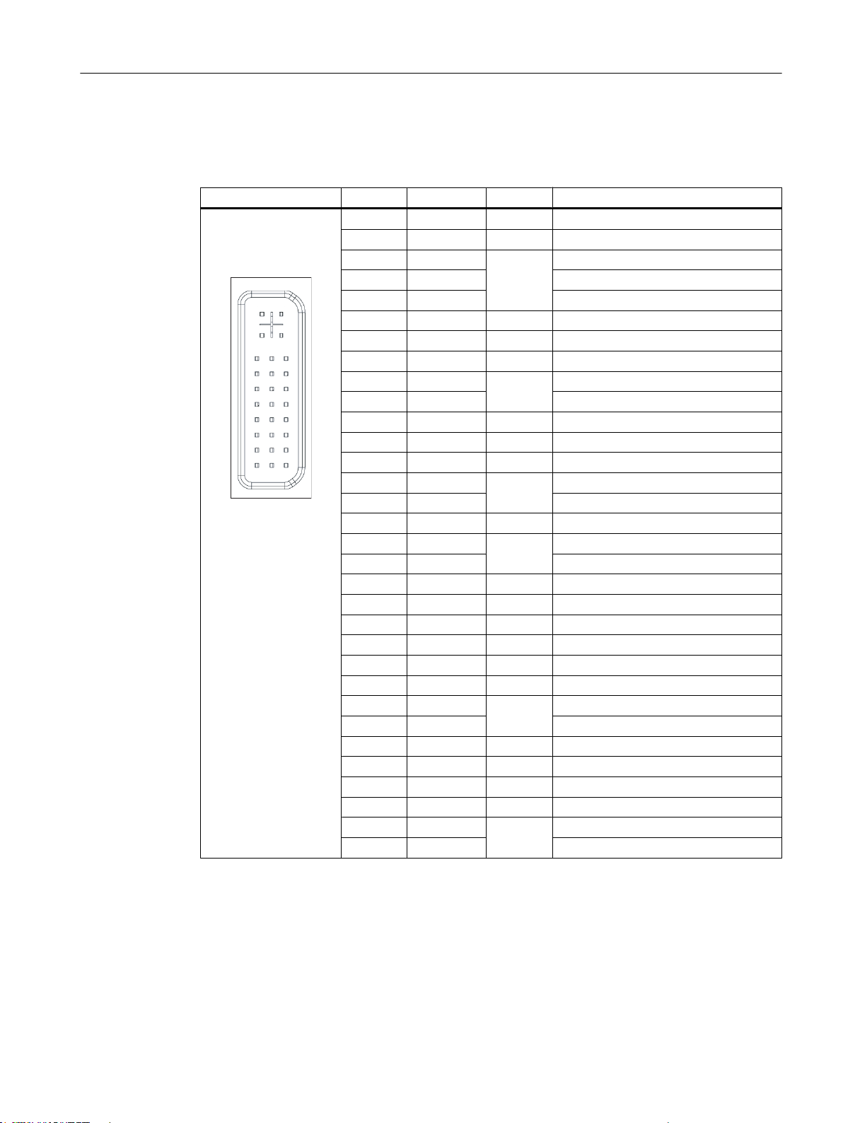
DVI-I interface
&
&
&
&&
Table 1-11 Assignment of DVI-I interface
Connector Pin Name Type Remark
S GND - Ground
S1 GND - Ground
C1 R
C2 G Green
C3 B Blue
C4 HSYNC O Horizontal synchronizing pulse
C5 GND - Ground
CSA GND - Ground
1 TX2N
2 TX2P TDMS data 2+
3 GND - Ground
4 N.C. - Not connected
5 N.C. - Not connected
6 DDC CLK
7 DDC CLK DDC data
8 VSYNC O Vertical synchronizing pulse
9 TX1N
10 TX1P TDMS data 1+
11 GND - Ground
12 N.C. - Not connected
13 N.C. - Not connected
14 + 5 V VO + 5 V
15 GND VO Ground
16 MONDET I Hot plug detect
17 TX0N
18 TXoP TDMS data 0+
19 GND - Ground
20 N.C. - Not connected
21 N.C. - Not connected
22 GND - Ground
23 TXCP
24 TXCN TDMS clock -
General information and networking
1.3 Connecting
Red
O
TDMS data 2-
O
DDC clock
B
TDMS data 1-
O
TDMS data 0-
O
TDMS clock +
O
I/O USB interface
Operator panel front: OP 012
Manual, 09/2016, A5E36371591B 27
All signals required for connecting operator panel fronts, with the exception of the display
interface, are assigned to this interface.
Associated interface cable: K1
Connector type: 2 x 13-pin socket connector
Page 28
General information and networking
1.3 Connecting
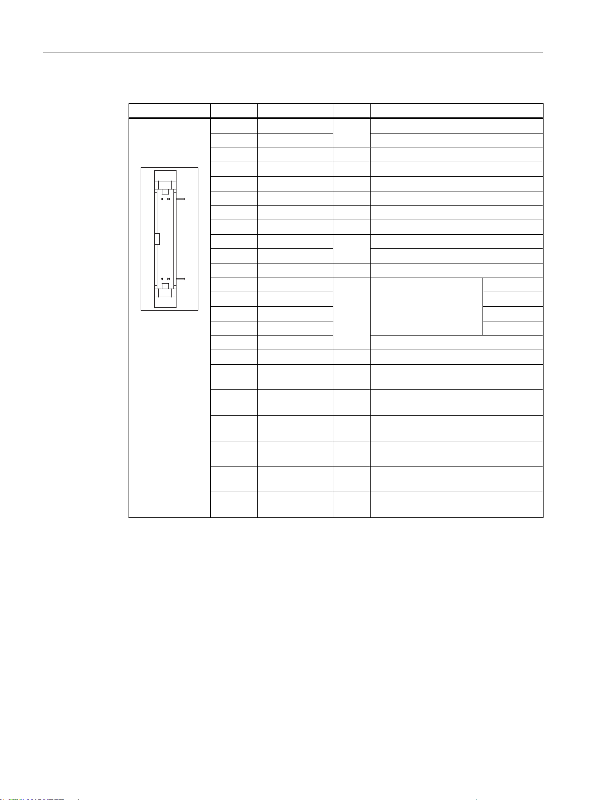
Table 1-12 Allocation of the I/O USB interface
Connector Pin Name Type Meaning
1 GND
2 P12C +power supply for backlight inverter
3 BL_ON O Backlight On
4 P5V_fused VO +5 V VCC (fused in PCU/TCU)
5 GND VO Ground
6 P3V3_fused VO +3.3 V VCC (fused in PCU/TCU)
7 - 10 N.C. - Not connected
11 P5V_fused VO +5 V VCC (fused in PCU/TCU)
12 USB_D1M
13 USB_D1P USB data+ Channel 1
14 GND VO Ground
15 LCD_SEL0
16 LCD_SEL1 2
17 LCD_SEL2 3
18 LCD_SEL3 4
19 RESET_N Reset signal (low active)
20 reserved - Reserved
21 HD_LED O HD LED, anode with 1 kΩ in series on the
22 DP_LED O MPI/DP LED, anode with 1 KΩ in series
23 Ethernet_LED O Ethernet LED, anode with 1 kΩ in series
24 TEMP_ERR O LED temperature sensor; anode with 1
25 RUN_R *) O Watchdog error LED, anode with 1 kΩ in
26 RUN_G O Watchdog OK LED, anode with 1 kΩ in
Ground
VO
USB data- Channel 1
B
Display type select signal
I
motherboard
on the motherboard
on the motherboard
kΩ in series on the board
series on the motherboard
series on the motherboard
1
LVDS display interface channel 1
28 Manual, 09/2016, A5E36371591B
Used to connect operator panel fronts with TFT displays with 640 x 480 pixels (VGA), 800 x
600 pixels (SVGA) or 1024 x 768 pixels (XGA).
Associated interface cable: K2, max. length: 0.5 m
Connector type: 2 x 10-pin socket connector
Operator panel front: OP 012
Page 29
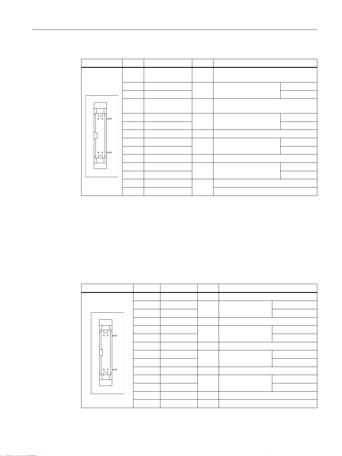
Table 1-13 Allocation of the LVDS display interface
Connector Pin Name Type Meaning
1/2 P5V_D_fused VO +5 V display supply voltage (fused in PCU/
3 RXIN04 RXIN0+ Bit 0 (+)
5/6 P3V3_D_fused VO +3.3 V display supply voltage (fused in PCU/
7 RXIN18 RXIN1+ Bit 1 (+)
9/10 GND - System ground (reference potential)
11 RXIN212 RXIN2+ Bit 2 (+)
13/14 GND - System ground (reference potential)
15 RXCLKIN-
16 RXCLKIN+ (+)
17/18 GND
19/20 N.C. Not connected
I LVDS input signal
I LVDS input signal
I LVDS input signal
O LVDS cycle clock signal
-
General information and networking
1.3 Connecting
TCU)
Bit 0 (-)
TCU)
Bit 1 (-)
Bit 2 (-)
(-)
System ground (reference potential)
LVDS display interface channel 2
Used for expanding the LVDS display interface channel 1 to control TFT displays with 1280 x
1024 pixels (SXGA).
Associated interface cable: K3
Connector type: 2 x 10-pin socket connector
Table 1-14 Allocation of the LVDS display interface
Connector Pin Name Type Meaning
1/2 GND - System ground (reference potential)
3 RXIN104 RXIN10+ Bit 0 (+)
5/6 GND - System ground (reference potential)
7 RXIN18 RXIN1+ Bit 1 (+)
9/10 GND - System ground (reference potential)
11 RXIN212 RXIN2+ Bit 2 (+)
13/14 GND V Ground
15 RXCLKIN16 RXCLKIN+ (+)
17 GND V Ground
18-20 P12VF VO +12 V fused
LVDS input signal Bit 0 (-)
I
LVDS input signal Bit 1 (-)
I
LVDS input signal Bit 2 (-)
I
LVDS cycle clock sig‐
O
nal
(-)
Operator panel front: OP 012
Manual, 09/2016, A5E36371591B 29
Page 30

General information and networking
1.3 Connecting
Rotary switch: Feed override X30
Connector designation: X30
Connector type: 2 x 5-pin plug connector, according to EN 60603-13 with coding
Max. cable length: 0.6 m
Table 1-15 Assignment of X30 connector (on delivery)
Pin Name Type Meaning
1 N.C. - Not connected
2 N.C. - Not connected
3 M V Ground
4 N.C. - Not connected
5 P5 V 5 V supply
6 OV_VS16
7 OV_VS8 Override rotary switch value 8
8 OV_VS4 Override rotary switch value 4
9 OV_VS2 Override rotary switch value 2
10 OV_VS1 Override rotary switch value 1
Override rotary switch value 16
I
Rotary switch: Spindle override X31
Connector designation: X31
Connector type: 2 x 5-pin plug connector, according to EN 60603-13 with coding
Max. cable length: 0.6 m
Table 1-16 Assignment of X31 connector (on delivery)
Pin Name Type Meaning
1 N.C. - Not connected
2 N.C. - Not connected
3 M V Ground
4 N.C. - Not connected
5 P5 V 5 V supply
6 OV_SP16
7 OV_SP8 Override rotary switch value 8
8 OV_SP4 Override rotary switch value 4
9 OV_SP2 Override rotary switch value 2
10 OV_SP1 Override rotary switch value 1
Override rotary switch value 16
I
Operator panel front: OP 012
30 Manual, 09/2016, A5E36371591B
Page 31
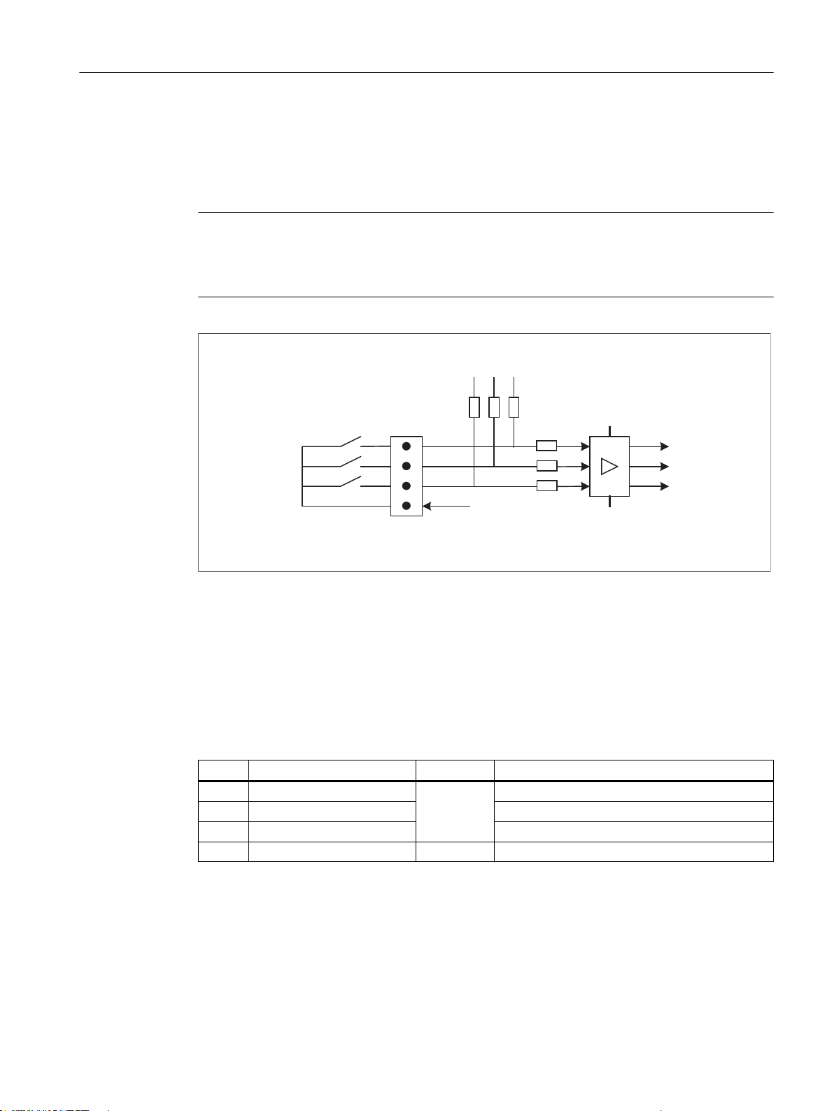
Optional customer buttons IN (X51 / X52 / X55)
;L
0*1'
0*1'
.7M,1
.7M,1
.7M,1
9
.
9
L
M
.
Only switches (passive inputs) may be connected via the X51, X52 and X55 connectors. X51
and X52 are typically used for connecting illuminated pushbuttons. The lamps in the buttons
are activated via X53 and X54. X55 has no corresponding outputs.
Note
Connection miniature handheld unit
Alternatively, at the inputs X51, X52 and X55, one miniature handheld unit may be operated.
For details, please refer to the corresponding section.
General information and networking
1.3 Connecting
Figure 1-5 Main circuit diagram of the input circuit for X51, X52 and X55
Connector designation: X51 / X52 / X55
Connector type: 4-pin plug connector
Max. cable length: 0.6 m
Table 1-17 Assignment of connector X51
Pin Name Type Meaning
1 KT-IN1
2 KT-IN2 Customer key 2
I
3 KT-IN3 Customer key 3
4 M V Ground
Operator panel front: OP 012
Manual, 09/2016, A5E36371591B 31
Customer key 1
Page 32
;
0*1'
0
3
.7287
.7287
.7287
;
0*1'
0
3
.7287
.7287
.7287
General information and networking
1.3 Connecting
Table 1-18 Assignment of connector X52
Pin Name Type Meaning
1 KT-IN4
2 KT-IN5 Customer key 5
3 KT-IN6 Customer key 6
4 M V Ground
Table 1-19 Assignment of connector X55
Pin Name Type Meaning
1 KT-IN7
2 KT-IN8 Customer key 8
3 KT-IN9 Customer key 9
4 M V Ground
Optional customer buttons OUT (X53 / X54)
Customer key 4
I
Customer key 7
I
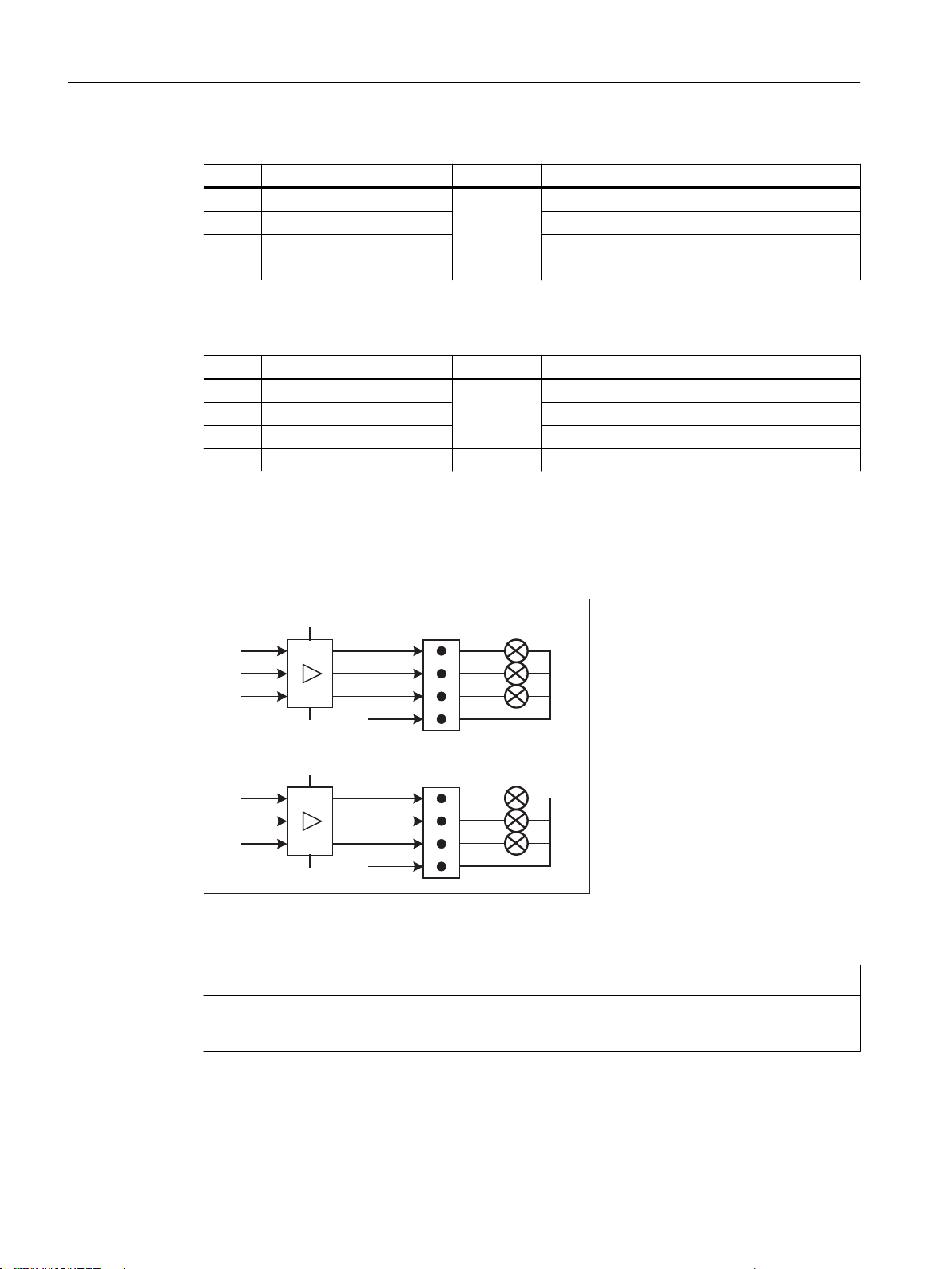
The short-circuit-proof outputs X53/X54 are provided to control lamps in the keys.
Lamps with 24 V and 2.4 W per output are recommended.
Figure 1-6 Main circuit diagram of the input circuit for X53 and X54
NOTICE
Damage to the electronics
Do not connect any relays, valves or other inductive loads.
32 Manual, 09/2016, A5E36371591B
Operator panel front: OP 012
Page 33

Connector designation: X53 / X54
Connector type: 4-pin plug connector
Max. cable length: 0.6 m
Table 1-20 Assignment of connector X53
Pin Name Type Meaning
1 KT-OUT1
2 KT-OUT2 Output 2 lamp
3 KT-OUT3 Output 3 lamp
4 M V Ground
Table 1-21 Assignment of connector X54
Pin Name Type Meaning
1 KT-OUT4
2 KT-OUT5 Output 5 lamp
3 KT-OUT6 Output 6 lamp
4 M V Ground
O
O
Output 1 lamp
Output 4 lamp
General information and networking
1.3 Connecting
Interfaces for two handwheels X60 / X 61
Interface: Handwheel 1 Handwheel 2
Connector designation: X60 X61
Connector type: 15-pin Sub-D socket
Max. cable length: 25 m
Table 1-22 Assignment of connectors X60/X61
Pin Name Type Meaning
1 P5HW V 5 V power supply
2 M V Ground
3 HW1_A / HW2_A I Handwheel pulses track A
4 HW1_XA / HW2_XA I Handwheel pulses track A (negated)
5 N.C. - Not connected
6 HW1_B / HW2_B I Handwheel pulses track B
7 HW1_XB / HW2_XB I Handwheel pulses track B (negated)
8 N.C. - Not connected
9 P5HW V 5 V power supply
10 N.C. - Not connected
11 M V Ground
Operator panel front: OP 012
Manual, 09/2016, A5E36371591B 33
Page 34
'7
'7
'7
'7
'7
'7
'7
'7
'7
'7
'7
'7
'7
'7
'7
'7
General information and networking
1.3 Connecting
Pin Name Type Meaning
12 N.C. - Not connected
13 N.C. - Not connected
14 N.C. - Not connected
15 N.C. - Not connected
Note
The handwheels can either be operated with TTL or differential signals.
You set the signal type using S1 (wire bridge) on the COM board.
The handwheels are supplied with 5 V ± 5% and 100 mA via the interface.
Contour and velocity specification via handwheel are not supported.
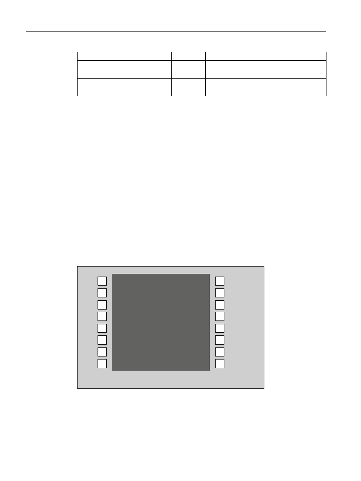
Interfaces for direct keys
X11 on the operator panel (OP) fronts can be used to fetch the state of the direct keys. The
connection of a 20-pin ribbon cable allows the direct keys to evaluate the following components:
● Direct key module (DTM)
● X70 in the machine control panels (MCP, MPP) and the handwheel connection module
(HAM)
● X205 on the Thin Client Unit (TCU)
The signals are then forwarded to the control over the various communications networks. Note
that DTM and HAM can be operated only with PROFIBUS DP.
Figure 1-7 Assignment of the direct keys to the vertical softkeys of an operator panel front
34 Manual, 09/2016, A5E36371591B
Operator panel front: OP 012
Page 35

General information and networking
16 digital inputs (5 V) can be fetched via the X11 connector.
Connector designation: X11
Connector type: 20-pin plug connector
Max. cable length: 0.85 m
Table 1-23 Assignment of connector X11
Pin Name Type Meaning
1 DT1
... ... ...
Direct key 1
O
16 DT16 Direct key 16
17 P5V
+ 5 V (fused)
18 P5V + 5 V (fused)
19 GND Ground
V
20 GND Ground
16 digital inputs can be polled by the X70/X205/DTM connector.
1.3 Connecting
Connector designation: X70/X205/DTM
Connector type: 20-pin plug connector
Max. cable length: 0.85 m
Table 1-24 Assignment of connector X70 (MCP, MPP, HAM) / X205 (TCU) / DTM
Pin Name Type Meaning
1 DT1
... ... ...
16 DT16 Direct key 16
17 P5V / CON1
18 P5V / CON2
2)
2)
19 GND Ground
20 GND Ground
1)
The inputs are electrically isolated for MCP / MPP / HAM and DTM.
2)
For the TCU, it is evaluated whether the direct keys have been connected.
3)
Power consumption: 100 mA for MCP / MPP / HAM; 500 mA for DTM
Table 1-25 Signal level
Direct key 1
1)
I
+ 5 V input voltage
+ 5 V input voltage
V
3)
3)
HIGH level: 5 V or open
Low level <= 0.8 V
Operator panel front: OP 012
Manual, 09/2016, A5E36371591B 35
Page 36
General information and networking
1.4 Networking
1.3.2 Handling membrane connectors
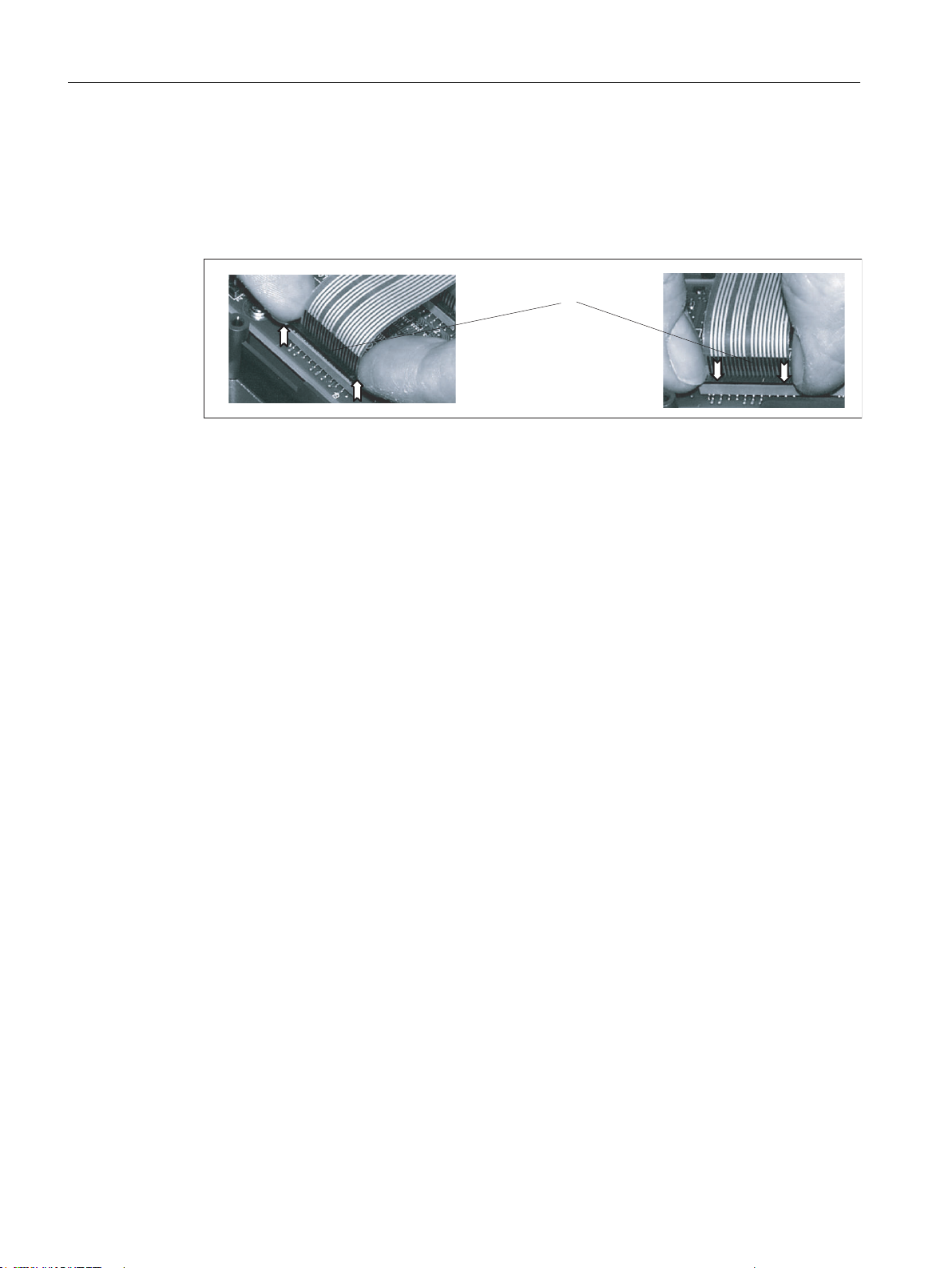
When replacing parts it can sometimes be necessary to disconnect membrane connectors
from the boards and reconnect them again.
This should be done as follows:
(1) Clamping frame of socket
Figure 1-8 Removing (left) and attaching (right) a membrane connector
Unplugging the membrane connector
1. Loosen the dark clamping frame of the socket by pushing it up with your fingernails until it
engages in its upper, unlocked position (Fig. left).
2. Carefully pull off the membrane connector upward.
Plugging in the membrane connector
1. With the clamping frame in the upper position, carefully plug the membrane connector into
the socket.
2. Lock it in place by pushing down the clamping frame (Figure right).
1.4 Networking
1.4.1 System settings
1.4.1.1 Settings for SINUMERIK solution line
Range of validity
This description is valid for:
● NCU 7x0.3 PN with NCU-Basesoftware (Linux-based)
● PCU 50.5 with PCU-Basesoftware (Windows XP, Windows 7)
Operator panel front: OP 012
36 Manual, 09/2016, A5E36371591B
Page 37

Introduction
Fundamentals
System network
General information and networking
1.4 Networking
This manual describes the structure and commissioning of the system network with
SINUMERIK solution line control and operator components with Ethernet-based
communication. The fundamentals of the system network are described first, details and
special cases are described in subsequent chapters.
The system network for SINUMERIK solution line is structured as a star topology with a central
Ethernet switch, to which all Ethernet-based components of the system are connected.
For an NCU the connection is executed via the X120 Ethernet socket, for PCU it is executed
via the "Ethernet 2" connection. There is no default for all other components with two Ethernet
connections. These components have an internal 2-port switch and may be used to connect
an additional operator component. Thus in this case there can be deviation from the strict star
topology.
In the system network the IP address 192.168.214.xxx with subnet mask 255.255.255.0 is preselected. Here there is precisely one DHCP server with DNS that can run on one NCU or one
PCU. The server ensures assignment of IP addresses to the Ethernet components in the
system network (DHCP clients) from a specified address band.
The following rules apply for assignment of IP addresses in the system network:
● For all NCUs and PCUs the commissioning engineer assigns fixed IP addresses in the
associated address bands, as well as appropriate computer names (host names). All other
(operator) components are automatically assigned an IP address from the DHCP server.
Its name is generated automatically (for MCP, MPP, HT 8), or is entered at commissioning
(TCU).
● If there are multiple NCU and/or PCU in the system network the system automatically
(depending on the start-up sequence) specifies the DHCP server and automatically ensures
synchronization of all necessary data so that the next time the system boots any other NCU
or PCU could take on the role of DHCP server. However it is a good idea to specify a DHCP
master. This is an NCU or PCU in the system network that is available at each system boot
and which regularly takes over the task of the DHCP server and DNS server.
Synchronization of data takes place in any event so that any other NCU or PCU can take
over this task. All non-master NCU / PCU wait in the system boot an adjustable length of
time for availability of the master.
Note
In a system network, on a boot server respectively - i.e. the NCU or PCU which
accommodates the active DHCP server - a maximum of 30 operator stations may be
operated simultaneously with a TCU.
A maximum of 10 operator stations with a TCU may connect up simultaneously with the
same HMI application when powering up.
Operator panel front: OP 012
Manual, 09/2016, A5E36371591B 37
Page 38

General information and networking
1.4 Networking
Connection to a company network
Each NCU can be connected via X130, and each PCU can be connected via "Ethernet 1" to
the company network. The company network is used to exchange operating software with
servers or to execute part-programs directly from servers in the company network. Company
network and system network should always be logically and also physically separated.
Service interface X127
The service interface X127 of the NCU is used for direct connection of a PG/PC for service
purposes. Here access with STEP 7 to the PLC, and with NCU 7x0.3 PN also to PROFINET
is possible.
With direct connection (peer-to-peer) of a PG/PC to X127 it is absolutely necessary that the
PG is operated as a DHCP client.
1.4.1.2 System boot with system network
System behavior at boot
As of NCU system software V2.4 SP1 and PCU-Basesoftware V8.1, system boot behavior is
based on the following principle:
● For configuration of an NCU 7x0 with a PU 50, the default for a network configuration is as
follows: The NCU keeps the default IP address 192.168.214.1 on X120, the PCU 50 keeps
the default IP address 192.168.214.241 on Eth2.
● For a configuration of more than 1 NCU 7x0 without PCU, with one or several PCU 50, then
a differentiation must be made between two cases:
– At boot automatically all address conflicts and DHCP conflicts are resolved and the
system is ready for operation. In this configuration there is no guarantee that all NCUs
and PCUs will always receive the same IP address at each system boot.
– If in the user's view there is a requirement that all NCUs, and possibly also the PCUs,
get a defined constant IP address at each boot, for example because the IP address is
entered in the respective PLC program, then the user must configure a fixed IP address
for each NCU 7x0/PCU 50 in question, in the basesys.ini file.
● The user can specify a DHCP master in the basesys.ini file.
● Assigning names:
– The user should assign meaningful names for all NCUs in the basesys.ini file; if not the
names will be generated automatically.
– A PCU 50 always has a computer name that can be changed as needed.
● The IP addresses of TCUs and MCPs are freely assigned within the specified address band
at each boot. The MCPs are identified in the PLC via their DIP switch setting.
Operator panel front: OP 012
38 Manual, 09/2016, A5E36371591B
Page 39
Using DNS name service
6ZLWFK
6,180(5,.'VO
3&8
7&8+77&87&8
0&3
Availability of the DNS (Domain Name System) name service offers the following advantages
for system network administration:
● The name service enables easier configuration with names instead of IP addresses for
management of operating units: All components in the system network can be addressed
via a symbolic computer name. This name can to some extent be freely assigned, to some
extent it is derived automatically from a DIP switch setting (MCP, MPP, EKS, HT 8, HT 2).
● A computer node in the system network (NCU, PCU, TCU, MCP, HT 8, etc.) can be
addressed solely through assignment of the IP address, either via a freely selectable name
or via an internally generated name in the system network, and thus becomes independent
from its network address in the system network. Thus a change in the network address
does not necessarily necessitate a series of additional setting changes.
● In addition, the name service is used by the system for address resolution for MCP/MPP,
direct keys, and EKS when changing the user authorization.
1.4.1.3 Thin Client Unit (TCU)
General information and networking
1.4 Networking
TCU overview
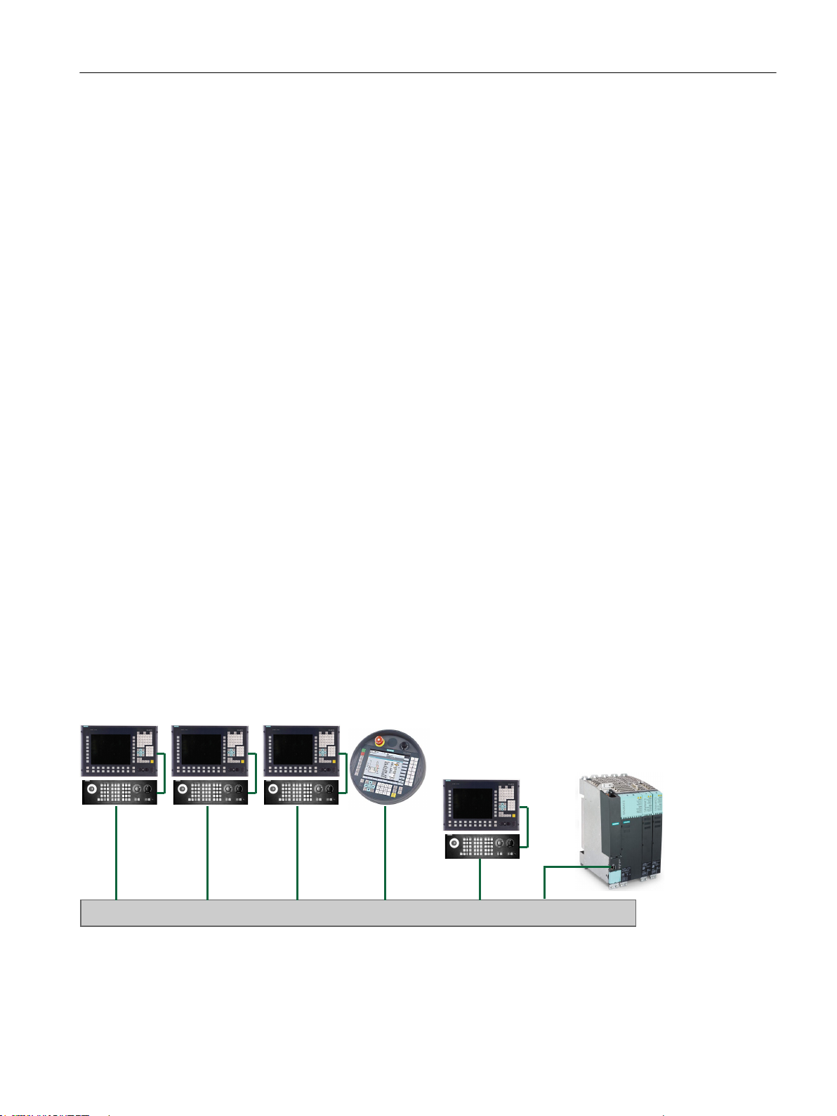
The Thin Client Unit (TCU) for the distributed configuration permits spatial separation of the
SINUMERIK operator panel front (OP/TP) and the SINUMERIK PCU or NCU. On the
SINUMERIK solution line, the TCU is used to display the user interface of the PCU 50 or the
NCU.
It is possible to connect one TCU to several PCUs/NCUs. All TCUs and PCUs/NCUs that are
connected to one another via a switch form the "system network". The user interface of a PCU/
NCU is copied to several OPs with one TCU each. In other words, all of the TCUs display the
same screen. Operator actions can only be performed on one TCU at a time. This TCU then
has user authorization. The PCU can also have its own OP connected directly to it.
The following diagram shows a configuration example for a distributed topology:
The mobile SINUMERIK HT 8 handheld terminal works on the thin client principle and
combines the functions of an operator panel with a machine control panel.
Operator panel front: OP 012
Manual, 09/2016, A5E36371591B 39
Page 40

7&8
General information and networking
1.4 Networking
The configuration and cabling of the whole plant system based on a permissible configuration
is described in the chapter 'Network configurations".
Supplementary conditions
For operation of a TCU:
● In the system network, the number of active TCUs is limited:
– a maximum of 2 TCUs: NCU 710.3 PN
– a maximum of 4 TCUs: NCU 720.3 PN or NCU 730.3 PN
– a maximum of 4 TCUs: PCU
Any number of TCUs can be operated in the system network.
● CompactFlash Cards cannot be used on the TCU.
● A 16 bit or 32 bit depth of color setting may be selected.
● If a PC keyboard is connected to the TCU, it is not possible to ensure that all special keys,
e.g., multi-media keys, will be transferred to the software of the NCU / PCU.
● Machine control panels connected via a PROFIBUS network are not supported for
switchover.
● Distributed memory media that are connected to the TCU via USB can be used.
1.4.1.4 Factory default settings
Meaning of the symbols:
○ Eth 1 as a DHCP client
● Eth 2 as a DHCP server
■ Eth 2 with a fixed IP address
Preconfiguration of the TCU
The TCU is configured as a DHCP client and primarily accepts IP addresses from SINUMERIK
components, from the DHCP server of such components that are inherent to SINUMERIK, for
example, an NCU at X120 or a PCU on the system network or from a default DHCP server.
The behavior of the TCU cannot be modified here.
A TCU is a SINUMERIK DHCP client.
The TCU has a single Ethernet connection.
A TCU executes a boot via the network. The boot server is the computer node from which the
TCU also obtains its IP address.
40 Manual, 09/2016, A5E36371591B
Operator panel front: OP 012
Page 41

Pre-configuration of the PCU
3&8
(WK(WK
1&8
;
;;
A PCU has two Ethernet interfaces with default settings suitable for use with SINUMERIK
solution line:
Preconfiguration of the NCU
On the X120, the NCU is preconfigured for the SINUMERIK DHCP protocol. The NCU is preselected here as a SINUMERIK DHCP server. On X120, the NCU occupies the fixed IP address
192.168.214.1 with the subnet mask 255.255.255.0 in its capacity as a DHCP server. The
DHCP server of the NCU assigns IP addresses from the range 192.168.214.10 –
192.168.214.239 to the DHCP clients. The behavior of the NCU on X120 cannot be
modified.
General information and networking
1.4 Networking
Eth 1 is pre-selected as a default DHCP client for connection to a
company network.
Eth 2 is pre-selected as a SINUMERIK DHCP server for connection
to a system network. On Eth 2 the fixed IP address
192.168.214.241 is pre-selected.
Restricting the available address band that is managed by the DHCP server of the NCU frees
up IP addresses 192.168.214.2 to 192.168.214.9 as well as addresses 192.168.214.241 to
192.168.214.254 for network nodes with fixed IP addresses.
On X130, the NCU is set as a default DHCP client for the address reference from a company
network. The IP address received here is specified by the DHCP server from the company
network.
On X127, an NCU is a standard DHCP server (in contrast to the SINUMERIK DHCP server).
On X127, the NCU has the fixed IP address 192.168.215.1 with the subnet mask
255.255.255.224). The IP addresses 192.168.215.2 – 192.168.215.23 are dynamically
assigned to the DHCP clients. The range 192.168.215.24 - 192.168.215.30 is reserved, and
can be used by stations on the network with a fixed IP address, e.g. by a modem.
Reserved IP addresses for NCU and PCU
The following defaults apply on delivery:
The NCU has three Ethernet connections:
- X120 to connect to the system network with an active DHCP serv‐
er (Eth 0)
- X130 to connect to the company network as a default DHCP client
(Eth 1)
- X127 as a service connection with an active DHCP server (Ibn 0)
Operator panel front: OP 012
Manual, 09/2016, A5E36371591B 41
● Connection to the system network with subnet mask 255.255.255.0:
Page 42
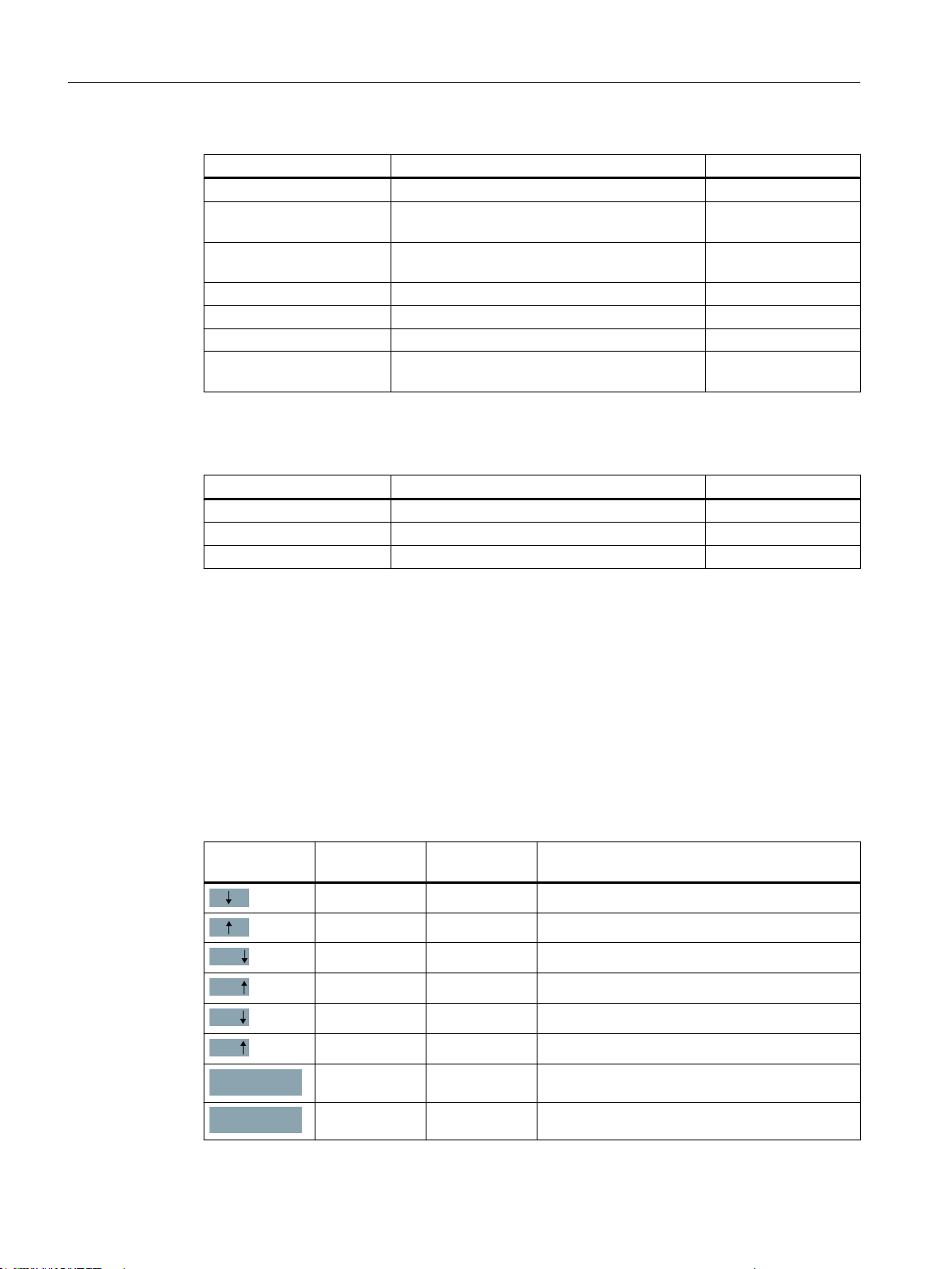
Page
Page
Char
Char
Cancel
Ok
General information and networking
1.4 Networking
IP address Network station Remark
192.168.214.1 NCU on X120 Default
192.168.214.2 – 9 For additional NCUs with a fixed IP address on
192.168.214.10 – 239 For additional TCUs, subsequently for additional
192.168.214.240 Reserved for EKS (Electronic Key System) Default
192.168.214.241 Fixed IP address of the PCU on Eth 2 Default
192.168.214.242 – 249 For additional PCUs with a fixed IP address Unassigned
192.168.214.250 – 254 For PGs with a fixed IP address (service con‐
● Service connection with subnet mask 255.255.255.224:
IP address Network station Remark
192.168.215.1 NCU on X127 Default
192.168.215.2 – 23 for service purposes with PG, PC DHCP clients
192.168.215.24 – 30 fixed IP address, for example for a modem Unassigned
Unassigned
the system network
DHCP clients
PCUs, NCUs, MCPs, MPPs
Unassigned
nection)
1.4.2 Commissioning TCU
1.4.2.1 Using the TCU's main menu
Key assignment
Functions of the keys and softkeys in the "Operator panel service system":
Softkey Key on OP External key‐
HSK1 <F1> Moves the cursor down a row
HSK2 <F2> Moves the cursor up a row
HSK3 <F3> Moves the cursor down a page
HSK4 <F4> Moves the cursor up a page
HSK5 <F5> Inserts text or digits
HSK6 <F6> Inserts text or digits
VSK7 ← Cancel / Return
VSK8 → OK / Confirm
Description
board
Operator panel front: OP 012
42 Manual, 09/2016, A5E36371591B
Page 43

General information and networking
1.4 Networking
"Main menu"
Softkey Key on OP External key‐
board
--- Pos1 Moves the cursor to the top row
--- End Moves the cursor to the bottom row
Description
Exceptions to the above are mainly the result of input fields. Where these are present, the left/
right cursor keys move the input cursor rather than performing an OK/cancel function. The
Return key takes you to the next field (like the "down" key) rather than closing the entire dialog
with OK. There are also Backspace (deletes character to the left) and Delete (deletes character
to the right) keys for editing text and numbers. The F5, F6, Backspace, Delete, and Select
keys (between the cursor keys on the panel) can be used to switch between Yes/No fields.
Touch panels without any additional keys still have a special function which allows you to edit
letters and numbers with HSK5/HSK6 by moving characters forwards or backwards. With a
touch screen, you can activate all the softkeys and even select rows in a menu simply by
touching them.
See also: How to calibrate a touch panel (Page 59)
The dialog "Main menu (TCU1)" is started with the menu back key and the key <MENU SE‐
LECT>:
Operator panel front: OP 012
Manual, 09/2016, A5E36371591B 43
Page 44
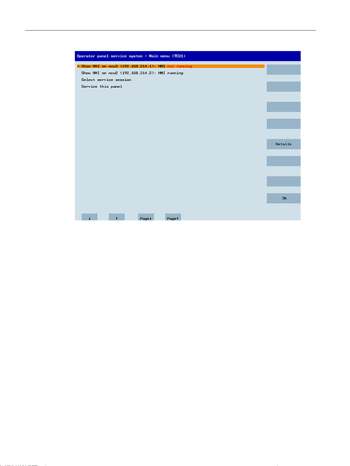
General information and networking
1.4 Networking
Figure 1-9 TCU menu: Main menu
The main menu contains:
● A "Main menu" title followed by the TCU name in brackets
● A central area listing the servers from config.ini. This is followed by two more fixed items,
"Select service session" and "Service this panel".
– The penultimate menu item, "Select service session", triggers a server scan which
detects all the VNC servers in the local (system) network. These are then displayed in
a session menu which largely reflects the main menu.
– The last menu item on the main menu, "Service this panel", opens the "Service menu
for operator panel" submenu.
● The right-hand side of the menu has a column containing 8 softkeys for use on a contextspecific basis.
● The lower section of the menu has a row of 4 softkeys for navigating with the cursor.
● There is an error line for displaying error messages directly above the row of softkeys.
Transient status messages also occasionally appear in this line.
● There is a further message line above this error line. The contents of this line can be set
from the servers using HWS commands.
Operator panel front: OP 012
44 Manual, 09/2016, A5E36371591B
Page 45
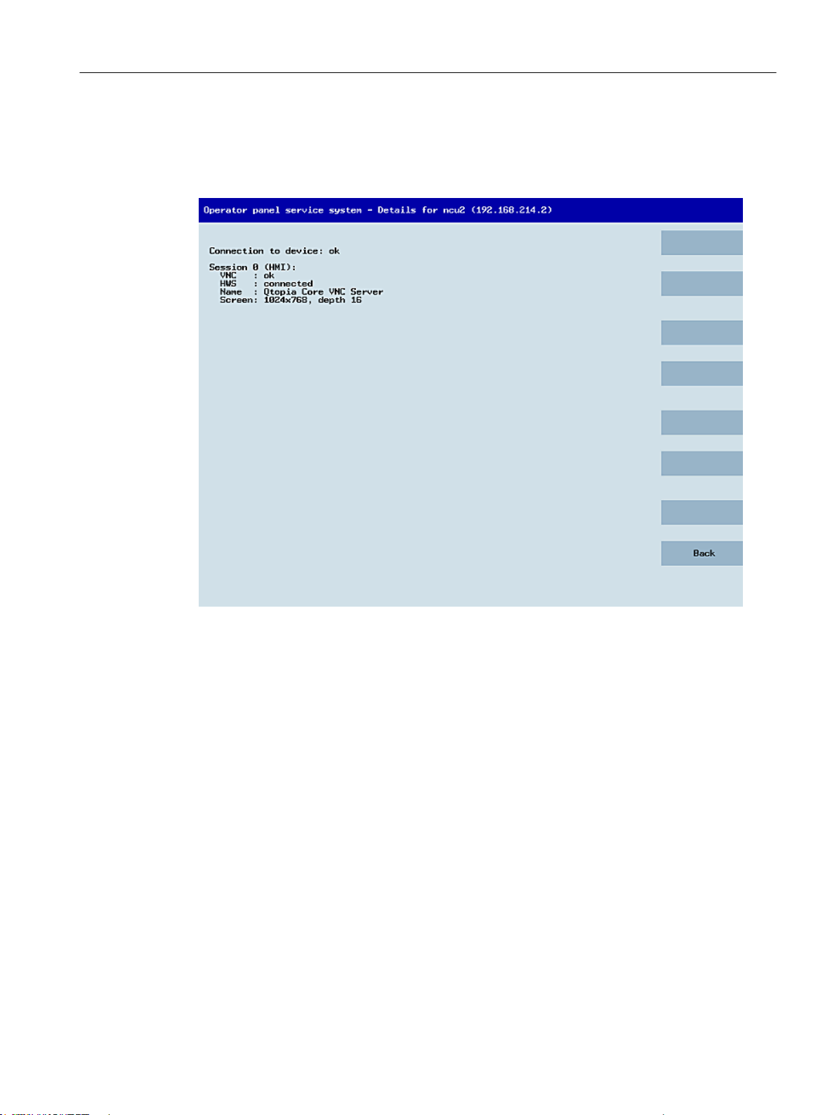
"Details" softkey
General information and networking
1.4 Networking
The following connection data for the selected device appears when the "Details" softkey is
pressed:
Figure 1-10 TCU menu: Connection data
1.4.2.2 Using additional TCU menus
"Service sessions" dialog
When "Select service session" is selected from the main menu, the resulting process begins
by triggering a server scan:
Operator panel front: OP 012
Manual, 09/2016, A5E36371591B 45
Page 46
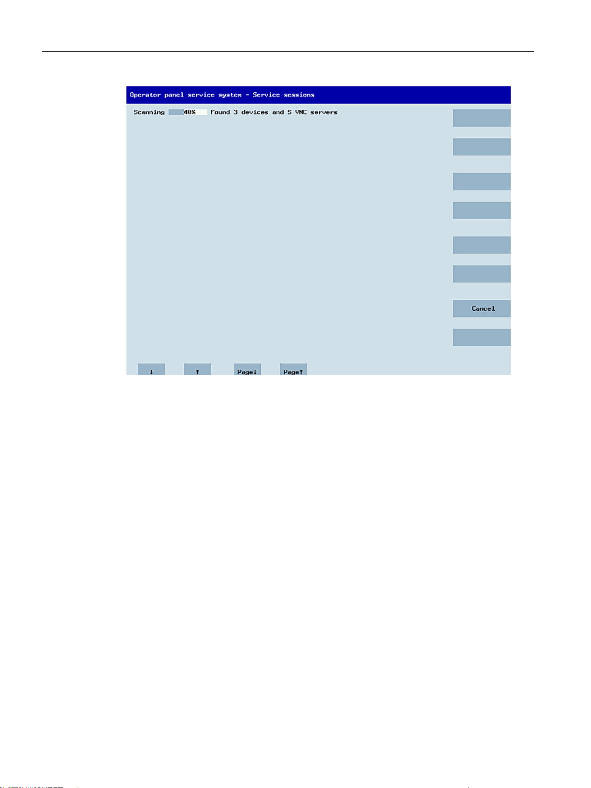
General information and networking
1.4 Networking
Figure 1-11 TCU menu: Scanning
After this, the following dialog appears:
Operator panel front: OP 012
46 Manual, 09/2016, A5E36371591B
Page 47
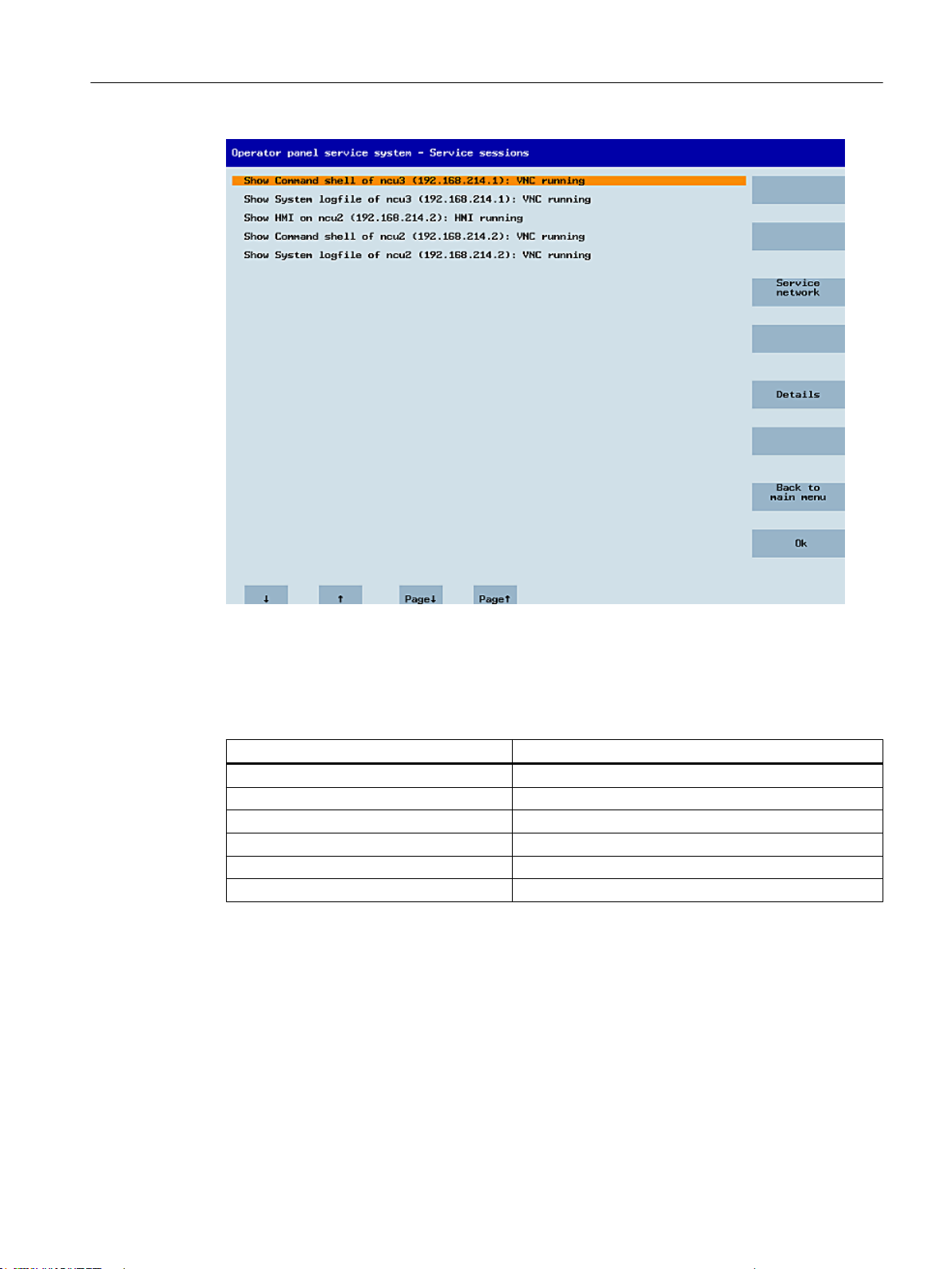
General information and networking
1.4 Networking
Figure 1-12 TCU menu: Active sessions
Central area with the server list:
The individual server lines contain either "Show WHAT on NAME (IP)" or the IP address only
where the name is unknown.
Session number VNC server
Session 0 HMI
Session 4 Command shell
Session 5 System logfile
Session 6 System Network Center (SNC)
...
Session <N> other server
These details are followed by a status message regarding the accessibility of the VNC server.
"Connection not ok" appears if it is already impossible to access the VNC server from the IP
side (if switched off, for example). If it can be accessed, a message shows whether an HMIVNC server is also accessible ("HMI running/not running").
The VSK8, Return or right cursor keys can be used to launch a VNC viewer for the selected
server.
Connection status:
Further details on the connection status can be called with the "Details" softkey. In the next
dialog, "not ok" or "not running" are accompanied by an additional error message with more
Operator panel front: OP 012
Manual, 09/2016, A5E36371591B 47
Page 48
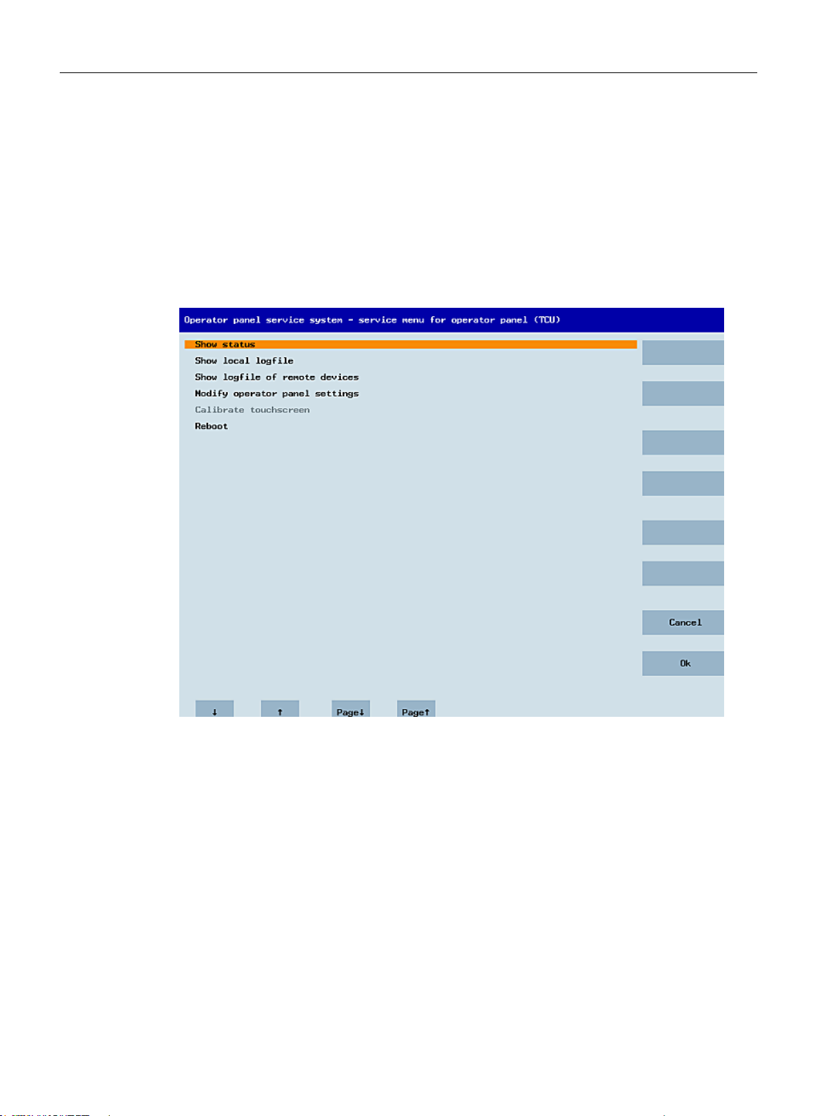
General information and networking
1.4 Networking
precise details on the reason for the loss of function. With more favorable scenarios, the
session name for the VNC server will also be specified along with its resolution.
The connection and HMI status are monitored on a regular basis in the background. This may
mean that these details change spontaneously if a change is made on the relevant server (for
example, it may be switched off, the HMI may become available, etc.).
"Service menu for operator panel (TCU)" dialog
The following dialog appears when "Service this panel" is selected from the main menu:
Figure 1-13 TCU menu: Service menu
Operator panel front: OP 012
48 Manual, 09/2016, A5E36371591B
Page 49
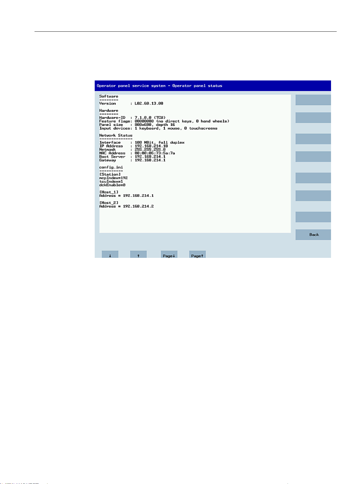
General information and networking
1.4 Networking
The following menu items are available here:
● "Show status" displays status information including the software version, HW information,
TCU network data, and the contents of the config.ini.
Figure 1-14 TCU menu: OP status
● "Show local logfile" displays a filtered version of the system logfile in the /var/log/
messages directory containing local TCU messages only.
Syslog messages received via the network are not displayed.
Operator panel front: OP 012
Manual, 09/2016, A5E36371591B 49
Page 50
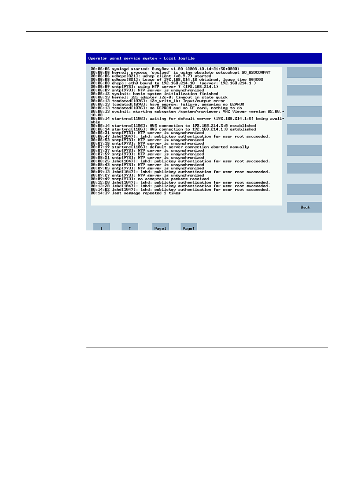
General information and networking
1.4 Networking
Figure 1-15 TCU menu: Local logfile
● "Show logfile of remote devices" displays the logfile of the other devices in the network:
The syslog messages of devices in the system network which send syslog messages by
broadcast, such as NCU 7x0, ...
● "Modify operator panel settings" calls a further submenu. Please refer to the next section.
● "Calibrate touch screen" is only active if there is a touch screen. This menu item recalibrates
the touch screen.
● "Reboot" restarts the TCU.
Note
Where the contents of a line exceed the space available, the remaining text runs onto the
next line so that you do not have to waste time scrolling across. When this occurs, the line
has a right-facing arrow at its right edge.
Operator panel front: OP 012
50 Manual, 09/2016, A5E36371591B
Page 51
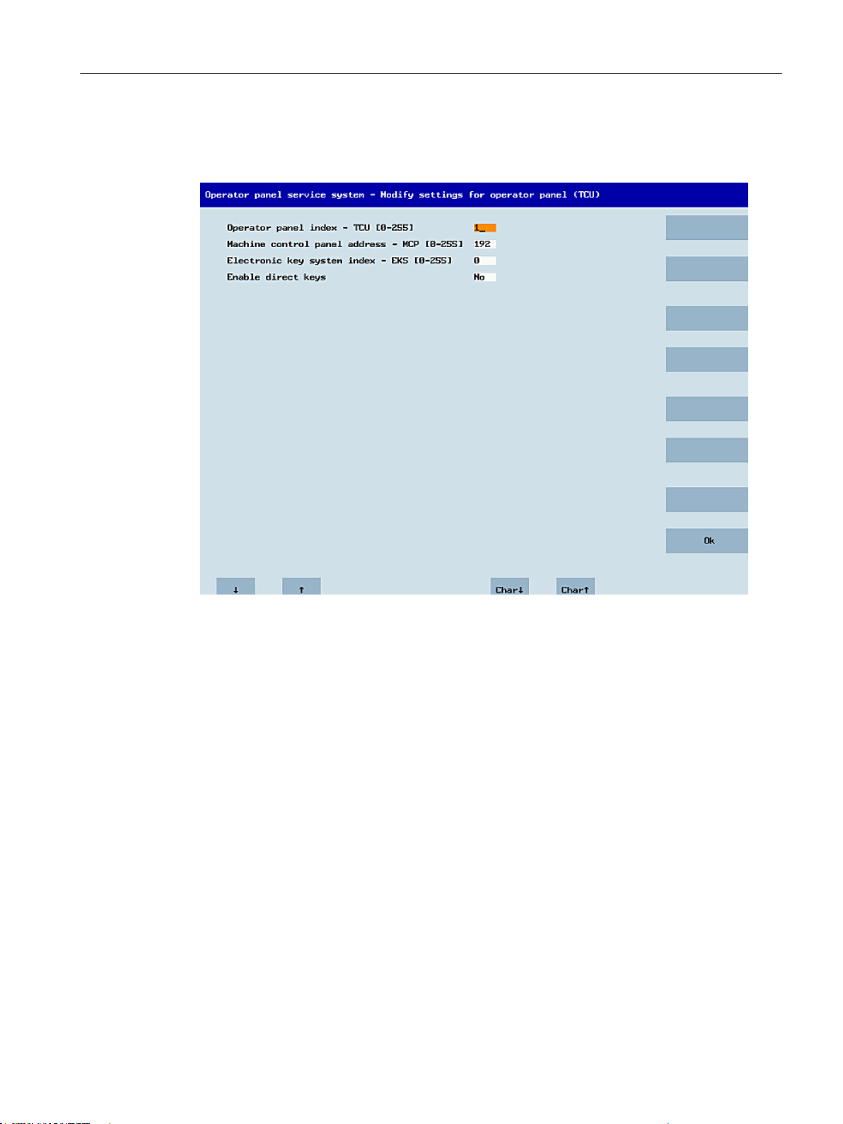
"Modify settings for operator panel (TCU)" dialog
The following dialog appears when "Modify settings" is selected from the main menu:
General information and networking
1.4 Networking
Figure 1-16 TCU menu: Settings
The central area is for setting the TCU parameters:
● "HT 8 individual mode" (yes/no)
This is only visible with HT 8, and is used to switch between Auto Mode and Individual
Mode.
There is no need to make any settings if an HT 8 is in Auto Mode, as the name is determined
automatically: ("DIP<n>") the MCP address and TCU index are determined by the DIP
setting ("DIP<n>").
It is possible, however, that another device is registered for the name selected. Such
situations may only prove to be temporary, as is the case when DIP settings or two HT 8
have been confused. For this reason, this status is not reported as an error immediately,
but identified as a possible problem instead ("potential name/DIP setting collision"). The
text will only read ("Name/DIP settings collision") if the situation remains unchanged after
some time has elapsed.
The process itself is unaffected, as the changes only relate to how the warning or error is
displayed. The explanatory text informs the user that they have probably assigned the same
DIP number twice and suggests they change one of them before rebooting the HT 8.
● "Operator panel index - TCU" (0-255)"
This specifies the TCU index. It matches the [Station] tcuIndex setting from the config.ini
file.
Operator panel front: OP 012
Manual, 09/2016, A5E36371591B 51
Page 52
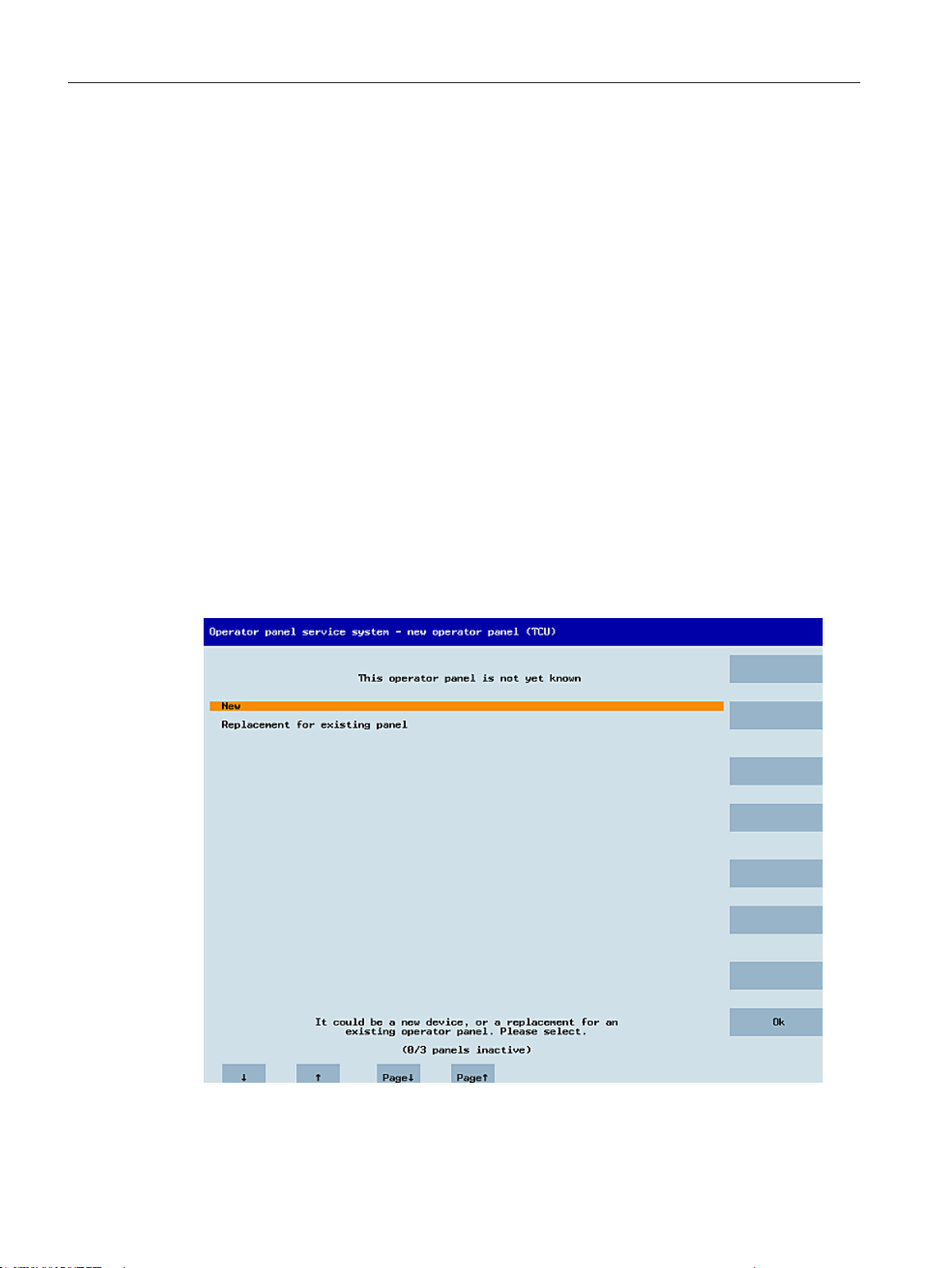
General information and networking
1.4 Networking
● "Machine control panel address - MCP" (0-255)
This specifies the address of the associated MCP. It matches the [Station] mcpIndex setting
from config.ini.
● "Electronic key system index - EKS" (0-255)"
This specifies the index of the associated EKS. It matches the [Station] eksIndex setting
from config.ini.
● "Enable direct keys" (yes/no)
This specifies whether direct keys (if present) should communicate with the PLC (yes) or
be treated as ordinary keys (no).
"OK" saves any modified values to the config.ini file or to the Flashstore (HT 8 individual mode).
Parameters for the "config.ini" file
Two steps need to be performed:
1. Select "New" or "Replacement for existing panel".
2. Select what is to be replaced.
When an unknown TCU (i.e. not yet registered with the boot server) is started, a selection
menu containing both the "New" and "Replacement for existing panel" items will appear. The
accessibility of all the registered TCUs is tested in the background.
The status of this test process appears in the message line: "(0/3 panels inactive)".
Figure 1-17 TCU menu: New TCU
Operator panel front: OP 012
52 Manual, 09/2016, A5E36371591B
Page 53
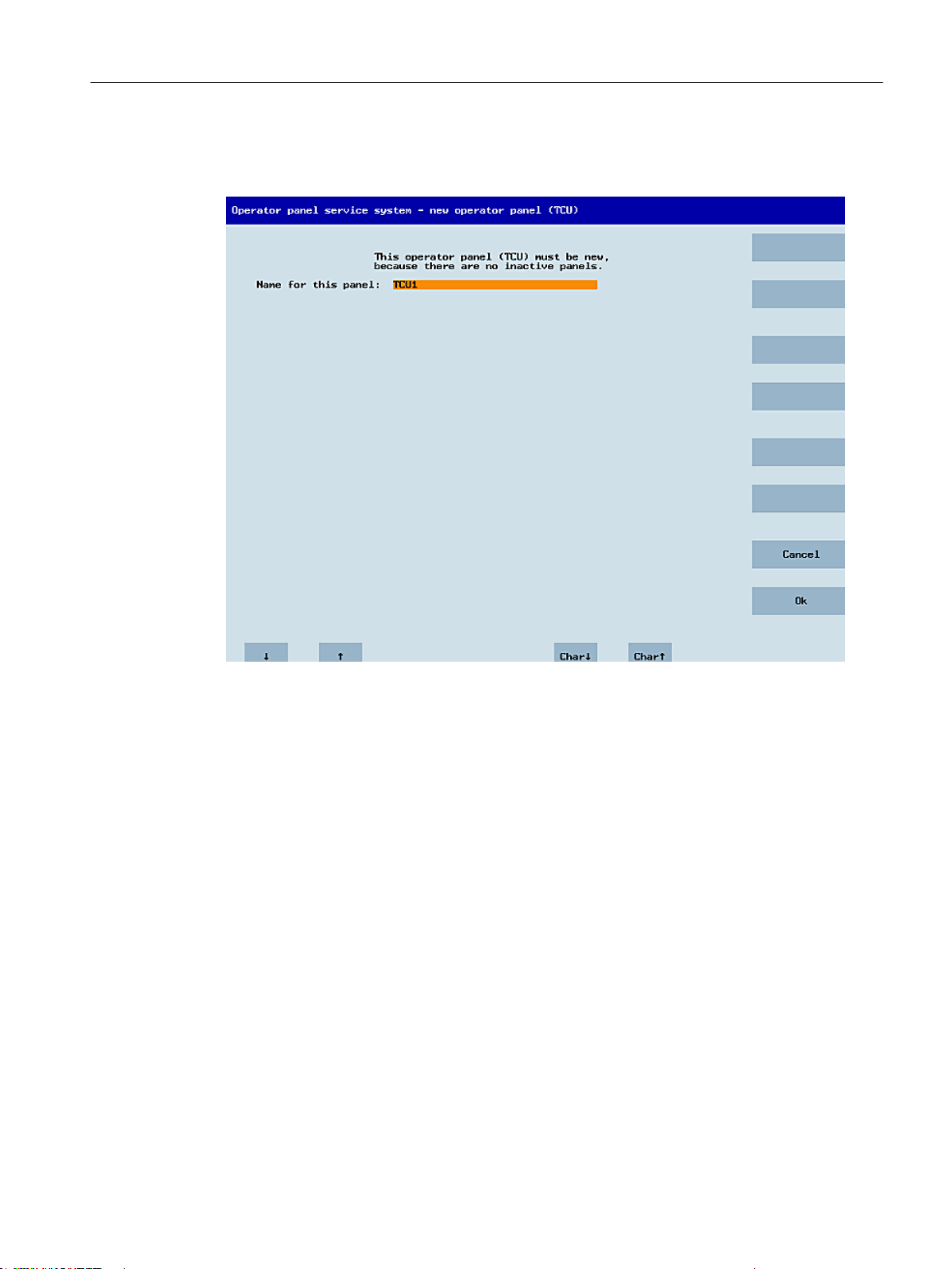
General information and networking
1.4 Networking
If all the TCUs are active, the new one cannot be a replacement. The system will then
automatically switch to the name assignment phase after a set period of time has elapsed.
Replacing a device
Figure 1-18 TCU menu: Name of TCU
If "Replacement" is selected, all the registered TCUs will appear in a selection menu. Those
which are active in the network will be grayed out. (As these are functioning, there should be
no question of replacing them.) The cursor automatically defaults to the first row for selection.
As the accessibility test is still running in the background, the active status of the rows may
change if panels are switched on or off.
If a name is ultimately chosen, it will be applied to the new TCU along with the associated
saved settings.
Operator panel front: OP 012
Manual, 09/2016, A5E36371591B 53
Page 54
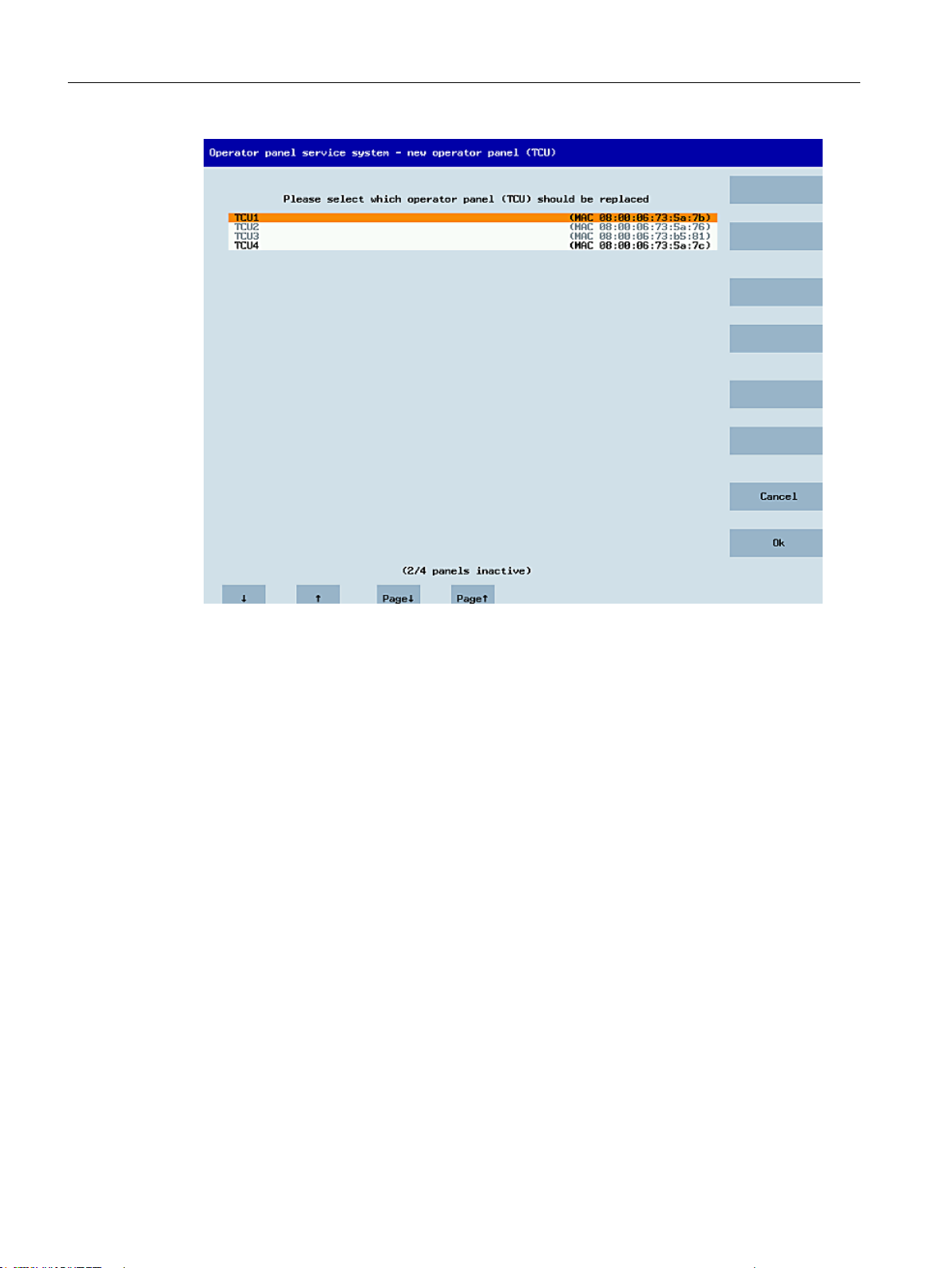
General information and networking
1.4 Networking
Figure 1-19 TCU menu: Spare TCU
Operator panel front: OP 012
54 Manual, 09/2016, A5E36371591B
Page 55
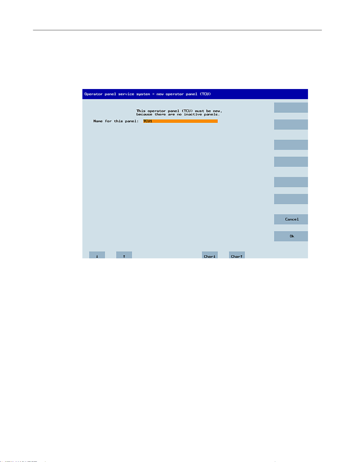
Assigning a name
General information and networking
1.4 Networking
If, as described above, the system automatically follows the "New" path, an additional message
will appear: "This operator panel (TCU) must be new, because there are no inactive panels."
This message will not appear if "New" is selected manually.
Figure 1-20 TCU menu: Name of TCU
An available TCU name is suggested in the input field, although the user is able to change
this. The default name is "TCU<N>", where <N> is the lowest number yet to be used. If,
however, the name is already allocated after the OK softkey has been pressed (which may
happen if a number of TCUs log on at the same time) and the suggestion has not changed, a
new and unused name will be specified.
If the name selected was still available, this will now be allocated, and the TCU settings can
still be adapted if required. To enable any changes to be made, a new dialog will appear in
which all the parameters have been pre-assigned their default values. You can make any
changes you like or just select "OK" to accept the existing values.
1.4.2.3 How to register a TCU on the system network
Preconditions
The boot server (NCU or PCU 50) defined in the system network as a DHCP master, must be
switched on and be available in the network.
Operator panel front: OP 012
Manual, 09/2016, A5E36371591B 55
Page 56

Operator panel ind ex - TCU [0-255]
Machine control panel address - MCP [0-255]
Electronic key system index - EKS [0-25 5]
Enable direct keys
1_
192
0
No
General information and networking
1.4 Networking
Sequence for a TCU
Procedure:
1. Connect TCU.
This opens the dialog "New operator panel (TCU)".
2. Select "New" to connect a new TCU and "OK" to confirm.
3. In the next dialog, accept the name suggested by the system or enter a name and confirm
this with "OK".
The following parameters are pre-selected for the TCU:
4. Restart the TCU to apply the new settings.
5. If you want to change the parameters, select "Main menu" → "Service this panel" → "Modify
operator panel settings".
56 Manual, 09/2016, A5E36371591B
Operator panel front: OP 012
Page 57

Sequence for the HT 8
HT8 Individu al Mode
Operator panel ind ex - TCU [0-255]
Machine control panel address - MCP [0-255]
Electronic key system index - EKS [0-25 5]
Enable direct keys
No
10
10
0
No
Procedure:
1. Connect HT 8 to a connection module and calibrate the touch screen.
Additional softkeys are available for convenient touch panel operation:
– "OK" has the same effect as the <INPUT> key
– Select "DEF" to save the "Default" settings.
– "Edit" has the same effect as the <F10> or <MENU SELECT> key.
2. Select HT 8 Individual Mode:
According to the default setting for an HT 8, "HT 8 Individual Mode" is deselected with "No".
This means "Auto" mode is activated for automatic detection in the system network. The
HT 8 is automatically detected based on its name "DIP_". If "HT 8 Individual Mode" is
activated with "Yes", the HT 8 is identified by its MAC address on the system network.
3. For an HT 8, confirm the "DIP..." name proposed by the system or adapt the name. You
can select any other characters.
Press the <INPUT> key to apply the following values as default settings for the HT 8:
General information and networking
1.4 Networking
The following message will then appear: "New TCU 'DIP10' registered."
Note
The TCU index is used to evaluate the direct keys. Direct keys can only be activated by
appropriate devices. For an HT 8 the TCU index cannot be set, but is assigned by the
system.
Activate direct keys
The signals from pressing the direct keys are sent directly to the PLC. In the PLC, the keys
appear as 16 digital inputs.
Additional information on programming the PLC is provided in:
References: Function manual basic functions, basic PLC program (P3 sl)
Definition: Operator panel
The term operator panel designates a unit that consists of an OP/TP, a TCU or PCU and a
machine control panel (MCP), that are connected to each other via Ethernet.
All TCUs and PCU 50 can be used along with OP/TP with "integrated TCU", e.g.: OP 08T,
OP 015T, TP 015AT.
Operator panel front: OP 012
Manual, 09/2016, A5E36371591B 57
Page 58
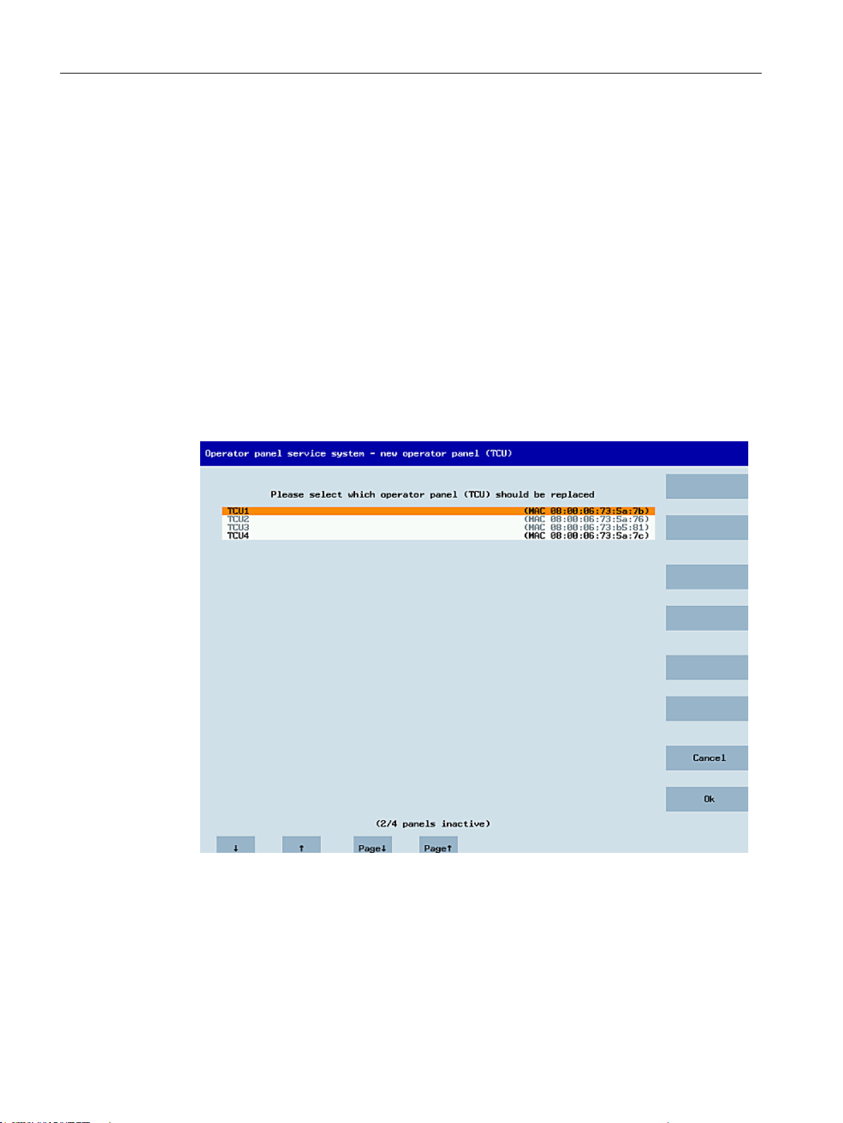
General information and networking
1.4 Networking
Specifying settings without machine control panel
If a PCU or a TCU has no Machine Control Panel (MCP), you must set one of the two following
options:
● MCP address = 0 or no entry
After the change of user authorization, there is no switchover of the machine control panel;
the previously active MCP remains active.
● MCP address = 255
If the user authorization is transferred to this PCU or TCU, the previous machine control
panel is deactivated and there is no active machine control panel from this point on.
Connecting a replacement TCU
Procedure:
1. Connect the new TCU.
The following dialog lists the TCUs on the system network along with their "active" or
"inactive" status.
Figure 1-21 TCU menu: New operator panel (TCU)
2. Select the name previously assigned to the faulty TCU from the "New operator panel (TCU)"
dialog. As a result, the new TCU is recognized on the network and acquires all of the
configuration settings from the TCU that has been replaced.
Operator panel front: OP 012
58 Manual, 09/2016, A5E36371591B
Page 59

See also
How to calibrate a touch panel (Page 59)
1.4.2.4 How to calibrate a touch panel
NOTICE
Service life of the touch screen
Do not touch the operating elements of the display with pointed or hard objects. This may
considerably reduce their service lives.
With each HT 8-device, a Touchpen (order no. 6FC5348-0AA08-4AA0) is delivered. This
should be used for calibration purposes and during operation.
Calibrate touch screen
The calibration is automatically started after switching on HT 8.
General information and networking
1.4 Networking
1. Follow the instructions on the screen:
2. Press the three calibration items one after the other.
This completes the calibration.
3. Press the corresponding horizontal softkey on the touch screen to close the command shell
and to re-establish the connection to the desired PCU.
Operator panel front: OP 012
Manual, 09/2016, A5E36371591B 59
Page 60
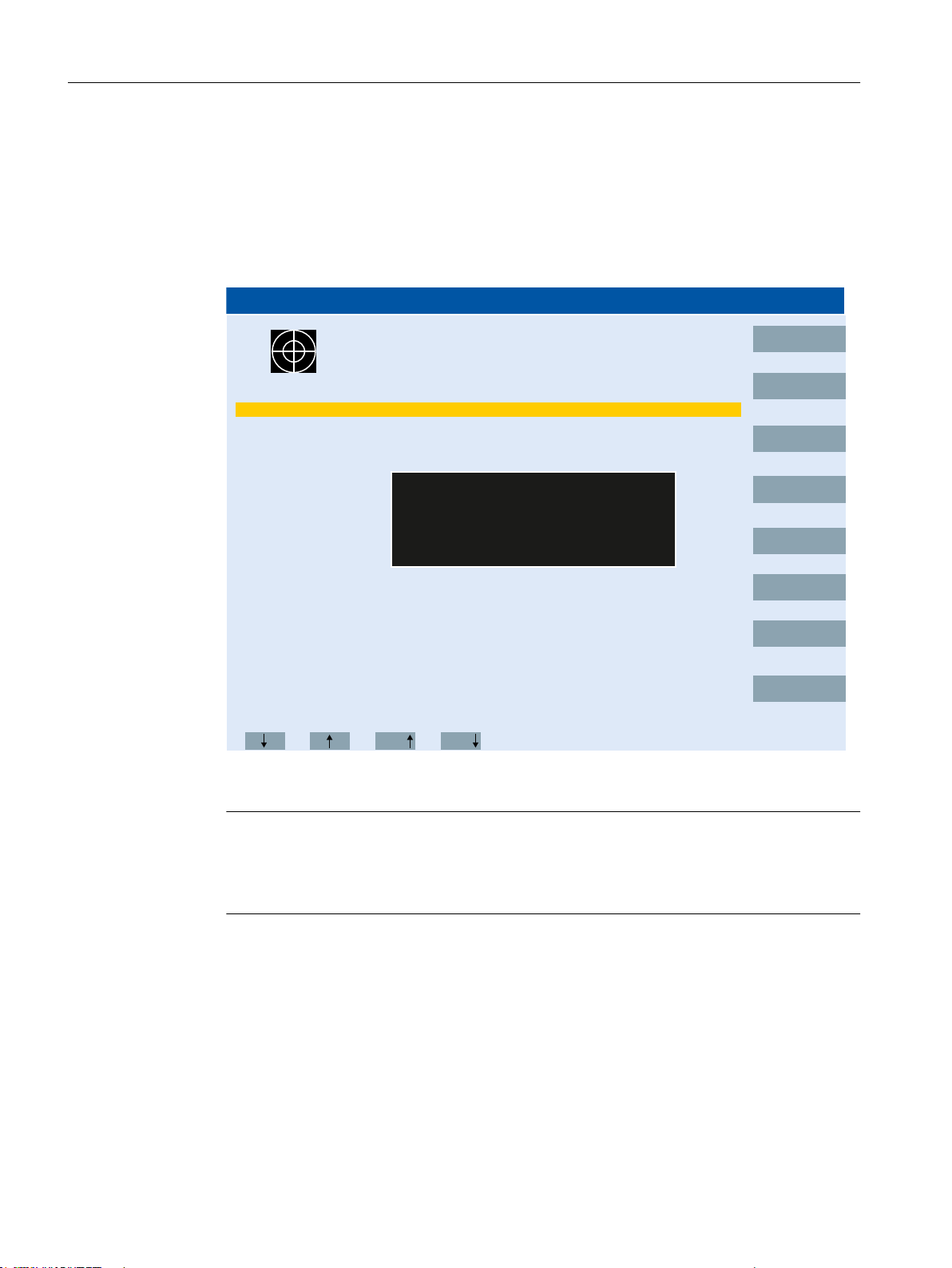
Operator panel service system - service menu for operator panel (TCU)
Ok
Show status
Show local logfile
Show logfile of remote devices
Modify operator panel settings
Calib rate touch screen
Reboot
Page
Page
Cancel
TOUCHSCREEN CALIBR ATION
(Screen Orie ntation)
Please touch upper left corner
General information and networking
1.4 Networking
Recalibrate touch screen
Procedure:
1. The key combination below can be used to initiate further TCU calibration during operation,
if required: <F9> + <F10>.
This corresponds to the key combination on an OP: Menu back key + <MENU SELECT>.
2. Select the menu item "Calibrate touch screen" to start calibration.
Figure 1-22 HT8 calibrating points
Note
The "Touchware" program, which is available with Windows XP, is deactivated on the TCU.
The calibration process on the HT 8 can alternatively be started with the following key
combination: <Recall> + <MENU SELECT> and then the <U> key.
60 Manual, 09/2016, A5E36371591B
Operator panel front: OP 012
Page 61
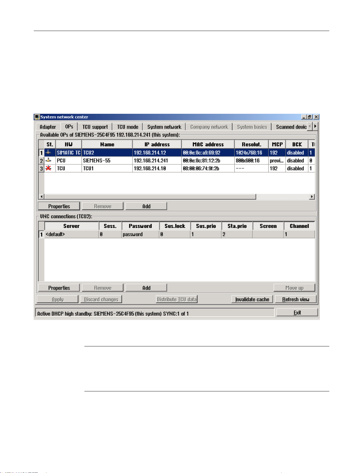
1.4.2.5 Connecting-up the SIMATIC Thin Client Touch Panel
Registration in the system network
The SIMATIC Thin Client Touch Panel behaves just like a TCU when connecting-up. When
registering in "Operator Panel Service System" enter a name in the system network. After this,
the device is available in the "Service Network Center" with the hardware ID "SIMATIC TC":
General information and networking
1.4 Networking
Figure 1-23 SIMATIC Thin Client
Note
The SIMATIC Thin Client Touch Panel has a USB connection at the rear, which behaves just
like the USB connection X204 of a TCU.
An external keyboard is recommended for commissioning and to operate the "Operator Panel
Service System".
Operator panel front: OP 012
Manual, 09/2016, A5E36371591B 61
Page 62
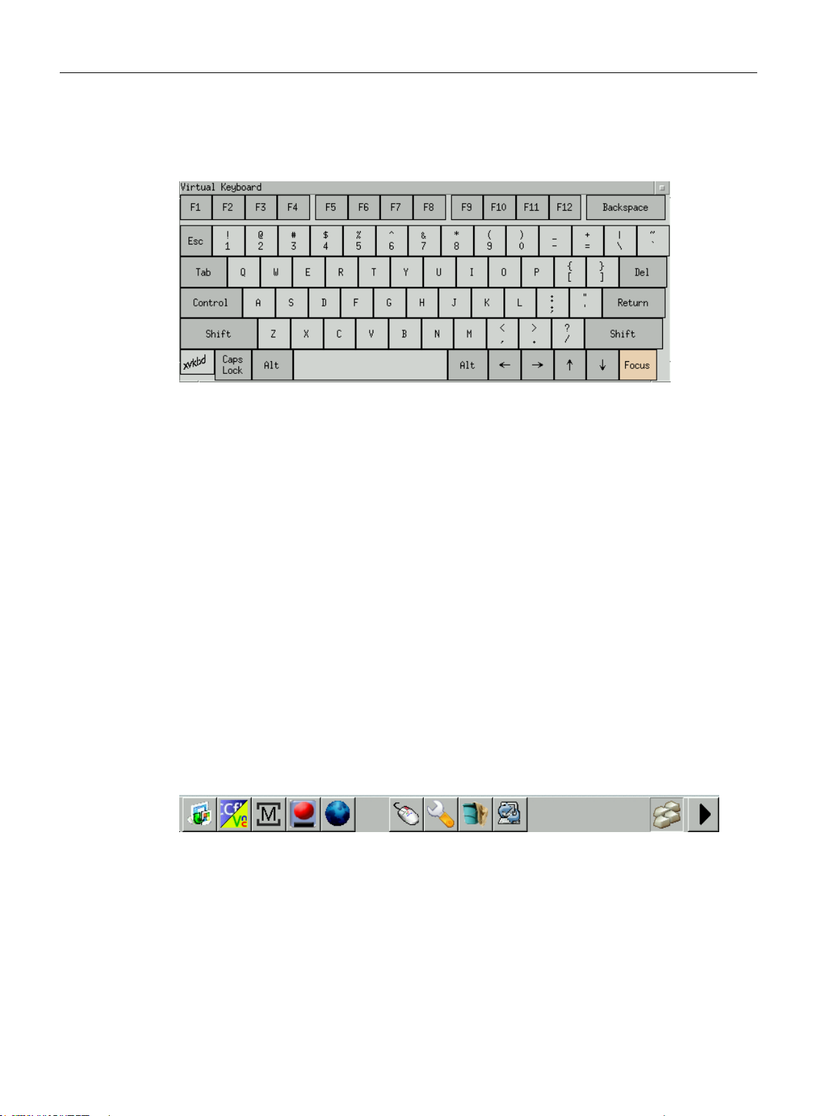
General information and networking
1.4 Networking
Operating the Touch Panel
To operate the Touch Panel, use the integrated keyboard:
Figure 1-24 Virtual Keyboard
The integrated keyboard is activated using the button to the far right on the start bar.
See also
How to register a TCU on the system network (Page 55)
Using the TCU's main menu (Page 42)
Reference
SIMATIC HMI, Operating instructions: Thin Client, Thin Client PRO
1.4.2.6 This is how you configure the SIMATIC Thin Client Touch Panel
Operating the start bar
The following functions are available in the start bar of the SIMATIC Thin Client:
To select the SINUMERIK mode, press the button:
Operator panel front: OP 012
62 Manual, 09/2016, A5E36371591B
Page 63
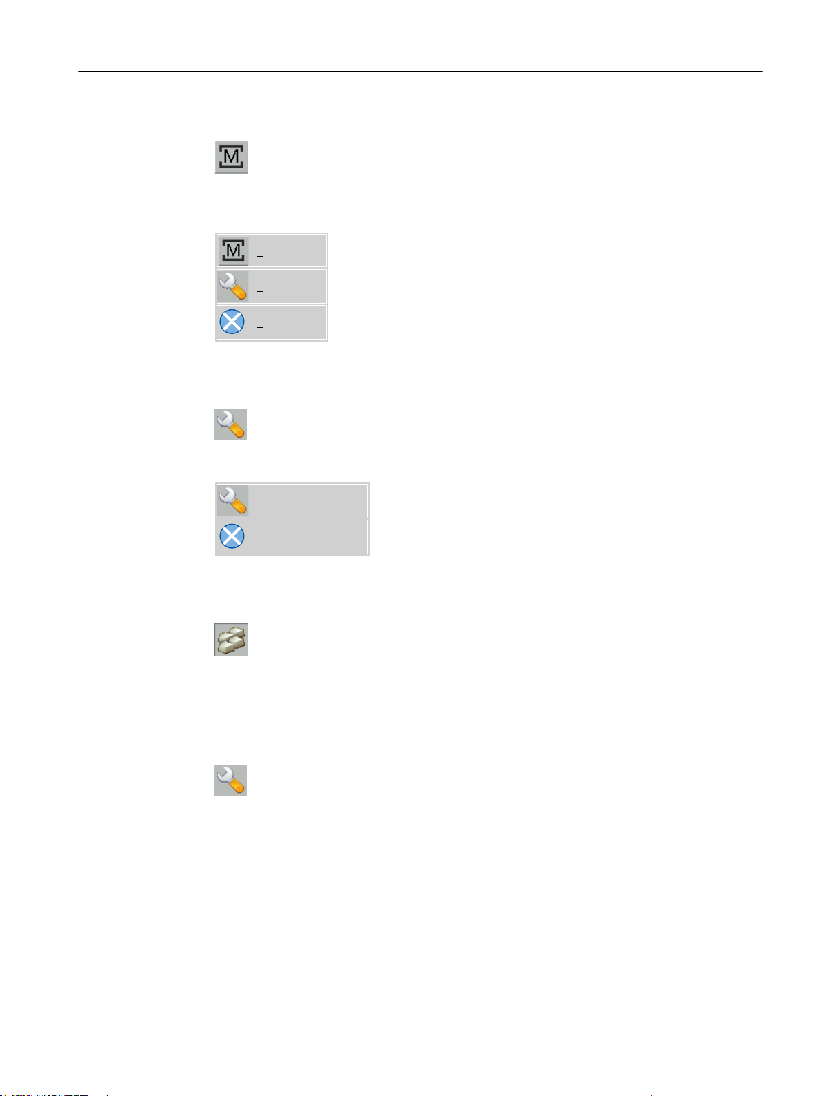
6HWWLQJV
2SHQ
&ORVH
&RQILJXUH7KLQ&OLHQW
&ORVH
General information and networking
1.4 Networking
● The following buttons are important for operation as SINUMERIK operator panel:
To configure the SIMATIC Thin Client, press the button "Settings". You therefore open the
"Operator panel service system":
To exit the SINUMERIK mode, press the button "Close".
● To make the configuration settings, press the button:
Preconditions
Select "Configure Thin Client":
To exit the SIMATIC configuration menu, press the button "Close".
● Press the button to activate the integrated keyboard:
To make the following settings, you must be logged on as administrator.
1. Press the "Settings" button:
2. Log on as a administrator using the specified password.
Result: As administrator you can see the complete menu of the SIMATIC Thin Client.
Note
All changes only become effective after pressing the "Enter" button on the "Virtual Keyboard"
on the relevant side.
Operator panel front: OP 012
Manual, 09/2016, A5E36371591B 63
Page 64

General information and networking
1.4 Networking
SINUMERIK mode when restarting
In order to return to the SINUMERIK mode automatically after a restart, proceed as follows:
1. In the "Applications" menu, select the "Autostart client application" tab.
2. Select the "SINUMERIK" option.
Calibrate Touch Panel
To calibrate the Touch Panel, proceed as follows:
1. In the "Device setup" menu, select the "Touch calibration" tab.
2. Follow the instructions and touch the Touch Screen at the appropriate points to calibrate.
1.4.2.7 Settings in the "config.ini" file
Boot server
The active boot server (DHCP server) is detected and displayed in the System Network Center
(SNC). The boot server accesses this configuration file accordingly. Changes to the config.ini
file do not become effective until the relevant TCU or PCU is next booted.
Note
If too much time (> 15 min.) elapses between commands when the user is making entries (e.g.
TCU name) as part of the initial TCU log-on process, the time-out error will be suppressed. No
error message will appear and the FTP connection will be reopened.
The config.ini file is created in the following directories:
NCU: /user/common/tcu/<TCU name>/common/tcu/
PCU (Windows XP): F:\user_base\common\tcu\<TCU name>\common\tcu\
PCU (Windows 7): C:\ProgramData\Siemens\MotionControl\user\common
\tcu\<TCU name>\common\tcu\
Configuration of the config.ini file
The config.ini file has the following configuration:
Parameter Range of values Default setting Meaning
[Station]
tcuIndex = Number 0 ... 255 DIP | 1 for TCU
mcpIndex = Number 1 ... 254 DIP | 192 for MCP via Industrial Ethernet
eksIndex = Number 0 ... 255 DIP | 0 for EKS
dckEnable = 0 0 or 1 0 for DCK
MaxHostIndex = Number Number of nodes (NCU, PCU or PC) to which you can
switch over.
[DEFAULT]
Operator panel front: OP 012
64 Manual, 09/2016, A5E36371591B
Page 65

General information and networking
1.4 Networking
Parameter Range of values Default setting Meaning
SessionNumber = Number
Password = String
SuspendLock = Number 0 or 1 0 0: No displacement disable
1: Displacement disable set
SuspendPriority = Number 1 ... 10 1 1: Lowest priority
10: Highest priority
StartupPrio = Number Boot sequence:
The lower the number the higher
the priority
ScreenOnFocus = String | Number Not relevant
ChannelOnFocus = Number Not relevant
[host_1]
Address = [hostname | IP-Adresse] From data file structure
SessionNumber = NUMBER
Password = STRING
SuspendLock = NUMBER 0 or 1 0 0: No displacement disable
1: Displacement disable set
SuspendPriority = NUMBER 1 ... 10 1 1: Lowest priority
10: Highest priority
StartupActive = 0 0 or 1 Display screen after boot
StartupPrio = NUMBER 0 ... not too high Boot sequence:
The lower the number the higher
the priority
ScreenOnFocus = STRING | NUMBER Not relevant
ChannelOnFocus = NUMBER Not relevant
[host_2]
...
[host_MaxHostIndex]
[T2M2N]
SK1 = ch_grp x 2 x 8 characters Empty Softkey inscription (2 lines)
SK2 = ch_grp x 2 x 8 characters Empty Softkey inscription (2 lines)
SK3 = ch_grp y 2 x 8 characters Empty Softkey inscription (2 lines)
...
SK32 = ch_grp z 2 x 8 characters Empty Softkey inscription (2 lines)
...
Operator panel front: OP 012
Manual, 09/2016, A5E36371591B 65
Page 66

General information and networking
1.4 Networking
Note
Connecting an MCP via PROFIBUS
If an MCP is connected via PROFIBUS, then the MCP Index = 0 should be set.
Compatibility of software versions
If a "config" file is available for the TCU, the data file structures of older versions are transferred
to the config.ini file and the data file structure is then deleted.
Comment
In the config.ini file comment lines are indicated by the # character preceding a line.
1.4.2.8 Settings in the "TCU.ini" file
Directories
The tcu.ini files is created in the following directories:
NCU: /siemens/system/etc/tcu.ini
/user/system/etc/tcu.ini
/oem/system/etc/tcu.ini
PCU (Windows XP): F:\addon_base\system\etc\tcu.ini
F:\user_base\system\etc\tcu.ini
F:\oem_base\system\etc\tcu.ini
PCU (Windows 7): C:\ProgramData\Siemens\MotionControl\siemens\System
\etc\tcu.ini
C:\ProgramData\Siemens\MotionControl\user\System
\etc\tcu.ini
C:\ProgramData\Siemens\MotionControl\oem\System\etc
\tcu.ini
Note
Only the following entries are evaluated by SINUMERIK Operate:
● VNCServer/VetoMode
● VNCServer/AlarmBoxTimeOut
● VNCServer/FocusTimeout
● VNCServer/AdaptResolution
● VNCServer/MaxActiveTCUs
● VNCViewer/ExternalViewerSecurityPolicy
Structure and content
In the tcu.ini file comment lines are indicated by the # character preceding a line.
Operator panel front: OP 012
66 Manual, 09/2016, A5E36371591B
Page 67

General information and networking
1.4 Networking
[VNCServer]
# VETO MODE
# VetoMode enabled:
# VNC server notifies the HMI regie before another
# panel gets the focus.
# VetoMode disabled:
# Focus timeout mode enabled (implicitly; see FOCUS TIMEOUT)
# (0=DISABLE, 1=ENABLE)
VetoMode=1
# FOCUS TIMEOUT
# Guaranteed time period (in sec) a panel can hold the
# focus at least before another panel can get the focus.
# The time period starts from the moment the panel has
# gained the focus.
FocusTimeout=10
# ALARMBOX TIMEOUT
# The time period (in sec) a messagebox is shown (i.e. is
# operable) in the case of VetoMode=1; no meaning else
AlarmBoxTimeOut=5
# RESOLUTION
0 = SYSTEM
1 = AUTO_OP_1 (default)
2 = AUTO_OP_2
3 = AUTO_MON_1
4 = AUTO_MON_2
5 = 640X480
6 = 800X600
7 = 1024X768
8 = 1280X1024
# RESOLUTION ADAPTION
# AdaptResolution enabled:
Operator panel front: OP 012
Manual, 09/2016, A5E36371591B 67
Page 68

General information and networking
1.4 Networking
# At system runtime, the system resolution is automatically
# adapted to the resolution of that panel which
# currently owns the focus.
# AdaptResolution disabled:
# The system resolution is set at system startup phase.
# At system runtime, system resolution remains unchanged
# whichever resolution the currently focused panel owns.
# (0=DISABLE, 1=ENABLE)
AdaptResolution=1
# COLOR DEPTH
# The value the system color depth is set at system
# startup phase
# ColorDepth SYSTEM:
# System color depth remains unchanged whichever value
# the color depth is currently set to.
# COlorDepth 16_BIT
# System color depth is set to 16 bit.
# COlorDepth 32_BIT
# System color depth is set to 32 bit.
# (0=SYSTEM, 1=16_BIT, 2=32_BIT)
ColorDepth=1
# INIT TIMEOUT
# Guaranteed time period (in sec) the HMI manager waits
# for VNC server initialization.
InitTimeout=300
# PCU STARTUP TIMEOUT
# Attention: The parameter is only provided for a PCU
# configuration with local attached OP !
#
# The startup phase is completed if this timeout period
# has passed and no registration of a TCU has been car-
# ried out at this time.
Operator panel front: OP 012
68 Manual, 09/2016, A5E36371591B
Page 69

General information and networking
PCUStartupTimeout = 90
# TCU STARTUP STEP TIME
# The startup phase starts at the first TCU registration.
# The startup phase is completed if the TCUStartupStepTime
# period has passed and no registration of another TCU has
# been carried out at this time.
TCUStartupStepTime = 30
[VNCViewer]
# EXTERNAL VIEWER MAX CONNECTIONS
# Maximum number of external Viewer Connections (1 or 2)
# ExternalViewerMaxConnections=2
ExternalViewerMaxConnections=1
1.4 Networking
# EXTERNAL VIEWER SECURITY POLICY
# The user rights, assigned to an external VNCViewer
# ExternalViewerSecurityPolicy=0 : no external viewers allowed
# ExternalViewerSecurityPolicy=1 : Guest Mode (View-Only)
# ExternalViewerSecurityPolicy=2 : Administrator Mode
# ExternalViewerSecurityPolicy=1
# EXTERNAL VIEWER MAX REFUSED REQUEST
# Number of refused external viewer requests, after which
# a timeout period is carried out for the viewer.
ExternalViewerMaxRefusedRequest=3
# EXTERNAL VIEWER CONNECTION TIMEOUT
# Timeout Period in seconds, after MaxRefusedRequest
# is reached. No viewer request is possible during the
# Timeout Period.
ExternalViewerConnectionTimeout=240
# EXTERNAL VIEWER REQUEST TIMEOUT
# The time period (in sec) the request-messagebox is shown (i.e. is
Operator panel front: OP 012
Manual, 09/2016, A5E36371591B 69
Page 70

General information and networking
1.4 Networking
# operable)
ExternalViewerRequestTimeout=20
# EXTERNAL VIEWER REQUEST TIMEOUTMODE
# The behaviour if request-timeout elapsed
# ExternalViewerReqTimeoutMode=0 : dismiss request
# ExternalViewerReqTimeoutMode=1 : accept request
ExternalViewerReqTimeoutMode=1
# REMOTE ACCESS IP-ADDRESS
# IP-V4-format
X127RemoteAccessIP=192.168.215.29
# MODEM IP-ADDRESS
# IP-V4-format
X127ModemIP=192.168.215.30
# SERVICE HOST
# NCU with teleservice adapter on its X127 interface
# Use "Self" for your own X127 interface
# IP-V4-format or DNS-Name or Self
X127ServiceHost=Self
[PingService]
# PING SERVICE MODE
# (0=DISABLE, 1=ENABLE)
PingServiceMode=0
# PING SERVER IP-ADDRESS
# IP-V4-format
PingServerIP=
# PING SENDING DATA
PingTransmissionData=
Operator panel front: OP 012
70 Manual, 09/2016, A5E36371591B
Page 71

General information and networking
1.4 Networking
# PING SERVER PORT-NUMBER
PingServerPort=
# PING TRANSMISSION PERIOD
# Period in minutes, in which transmission data will be sent
PingTransmissionPeriod=2
# PING TRANSMISSION INTERVAL
# Time interval in seconds between two pings
PingTransmissionInterval=5
[externalTcu]
# EXTERNAL TCU IP-ADDRESSES
# List of accepted TCUs in IP-V4-format (index 1 to maximal 16)
ExternalTcuIP_1=
[TCU_HWSService]
# TCU CONNECT TIMEOUT
# Guaranteed time period (in sec) the HMI manager waits
# for TCUs recognized as connected TCUs by the TCU_HWS
# service.
TCUConnectTimeout=30
# TCU CONNECT TIMEOUT FOR HEADLESS STARTUP
# Guaranteed time period (in sec) the HMI manager waits
# for TCUs recognized as connected TCUs by the TCU_HWS
# service, if a PCU panel doesn't exist and no TCUs are
# connected till now. This time period is effective ad-
# ditionally to the time period TCUConnectTimeout.
HeadlessTCUConnectTimeout=60
Operator panel front: OP 012
Manual, 09/2016, A5E36371591B 71
Page 72

General information and networking
1.4 Networking
Prerequisite
Note
The "Operation without SINUMERIK OP" option is required when using more than 1 external
VNC Viewer.
Operator control without SINUMERIK OP
If the "Operation without SINUMERIK OP" option is set, then a list of viewers that can be
assigned in tcu.ini is handled by the system just like internal viewers (=TCU); this means that
these viewers have full user authorization and participate in the user rights management.
Towards the outside, they behave just the same as the viewer on the SINUMERIK operator
panels.
Restrictions
Restrictions for such external operator control units are:
● Neither MCP and direct keys nor an EKS system can be assigned. This also means that
these devices cannot be activated to be an operator control unit in the system.
● Direct control keys cannot be triggered, i.e. the softkeys to the direct keys can be triggered
in the operating software. However, the keys do not appear in the direct key image to the
PLC.
● There is no configuration file config.ini, as for a TCU, i.e. the settings to be made to a TCU
are not possible for such an operator control unit (power-up behavior, displacement, t:m:n);
however, the displacement mechanism to the external operator control units is effective.
● An external operator control unit is never signaled as active operator station in the PLC.
Configuring the external operator control units in the tcu.ini file in section:
[externalTcu]
# EXTERNAL TCU IP-ADDRESSES
# List of accepted TCUs in IP-V4-format (index 1 to maximal 16)
ExternalTcuIP_1=
The desired screen resolution can also be set in the file tcu.ini:
[VNCServer]
Resolution = ...
1.4.2.9 Displacement mechanism for TCUs
Supplementary conditions
The following supplementary conditions apply when operating the TCU:
2 active TCU connected in parallel to NCU 710.3 PN
Operator panel front: OP 012
72 Manual, 09/2016, A5E36371591B
Page 73

Configuration
General information and networking
1.4 Networking
4 active TCU connected in parallel to NCU 720.3 PN, NCU 730.3 PN
4 active TCU connected in parallel to PCU
To operate a machine with more operating stations then the maximum number the
displacement mechanism ensures that only the permitted number of TCUs are active in
shadowing grouping. The remaining TCUs are switched to a passive mode, which means they
no longer represent a load relative to the resources. Thus the number of TCUs that can be
connected to one HMI application is practically no longer limited, the limitation is the number
of concurrently active TCUs.
There are two new entries in the config.ini file for a TCU for the displacement mechanism:
● SUSPENDLOCK: controls whether the TCU can be displaced via the displacement
mechanism.
SUSPENDLOCK = 0 means that a displacement disable is not set (preset), i.e. the TCU
may be displaced by any other TCU.
SUSPENDLOCK=1 means that this TCU can never be displaced.
● SUSPENDPRIORITY: This entry specifies a priority for the displacement mechanism to the
TCU. In a displacement process the TCUs among the active TCUs with the lowest priority
that do not have a displacement disable will displaced. The priority is specified as numeric
value in the range 1 - 10.
The preset is 1 (lowest priority).
Displacement rules
The TCU can assume the following states:
● The TCU is active and has user authorization: This can be identified as the TCU shows the
● The TCU is active, however, in the monitoring mode (i.e. it presently has no user
● The TCU is passive: The TCU shows the selection menu of the possible connections
When a TCU boots, the TCU always attempts to establish the first connection specified in its
config file. The TCUs from a shadowing group establish their specified connection one after
the other as long as the maximum number of permissible active operator units is not exceeded.
If a TCU encounters the situation that this number is already reached in its power up, then it
attempts to obtain a connection via the displacement mechanism. If it can displace a formerly
Note
If you set a displacement disable for a TCU then specification of a displacement priority is
unnecessary because it never is used due to the displacement disable.
screen of the operating software and the screen is bright.
authorization): This can be identified as the TCU shows the screen of the operating
software, however, it is darkened in comparison to the TCU with user authorization.
instead of a screen of the operating software, and the softkey for selection of the last active
connection of the TCU is shown in color.
Operator panel front: OP 012
Manual, 09/2016, A5E36371591B 73
Page 74

General information and networking
1.4 Networking
active operator unit then it takes on the active status itself, otherwise it transitions to passive
status immediately after booting.
1.4.2.10 Disable switchover between TCU via PLC
Overview
The TCU switchover disable offers the option of dynamically disabling switchover from one
TCU to the next when the system is running via the PLC. For the duration of the disable, a
user authorization request to change user authorizations between TCUs will be ignored by the
system and rejected.
The rejected user authorization request causes a message to be output in the dialog line of
the HMI, in the form of a feedback message for the requester. The message disappears after
five seconds.
HMI ↔ PLC data interface
The “switchover disable” function is always active and does not have to be switched on
explicitly. The function is controlled by a data bit in the PLC. The HMI transfers the active OP
to the PLC, thus forming the basis of the control function in the PLC.
The control bits and control information for this function are stored in the m:n data interface of
the PLC. In terms of m:n, this function can be operated separately for the currently overridden
HMIs in both m:n online interfaces (DB19.DBW120 ff for HMI1 and DB19.DBW130 ff for HMI2).
If a system is not running an m:n, only the first m:n online interface is used for this function.
Switchover disable is controlled by a TCU_SHIFT_LOCK bit, managed by the user, on each
HMI in the PLC. The bit address for the first HMI is DB19.DBB126.6 and DB19.DBB136.6 for
the second HMI.
The PLC m:n online interface is expanded so that byte DB19.DBB118 is still added to the first
interface and byte DB19.DBB119 to the second. These bytes acquire the index of the active
TCU (of the active OP) for the appropriate HMI. The byte is called TCU_INDEX. The
appropriate HMI uses the TCU index configured for the active TCU to describe the TCU_INDEX
byte.
The TCU_SHIFT_LOCK bit is monitored by the appropriate HMI. A value = 1 triggers the
switchover disable; switchover is enabled if the value returns to 0. The TCU_SHIFT_LOCK bit
can be set, for example, to the PLC by the user pressing a key or it can be managed by the
PLC user program according to its own logic. The TCU_SHIFT_LOCK bit is managed in the
PLC exclusively by the user; the HMI only accesses this bit in read-only mode.
The HMI assigns the configured index of the TCU or PCU whose OP currently possesses user
authorization in the shadow grouping. If no OP is active, a value of 0 is entered in TCU_INDEX.
If no TCU index is configured for the active TCU (active OP), the value 255 = undefined is
presented as the TCU index. This means that the values 0 and 255 may not be configured as
the TCU index.
Operator panel front: OP 012
74 Manual, 09/2016, A5E36371591B
Page 75

Configuration
Operating principle
General information and networking
1.4 Networking
The TCU index and machine control panel address (MCP address) are configured on the PCU.
The TCU index is set in the "OP Properties" dialog of the "System Network Center" program.
If the TCU_SHIFT_LOCK bit is set for switchover disable, a user authorization request is not
carried out independently of the mode set on the HMI for allocation of user authorizations (veto
mode), i.e., a change of user authorization is rejected.
This message appears on all OPs for approximately 5 seconds:
"No switchover: Switchover disable set in current PLC."
While this message is displayed, operations on the OP with the user authorization can still be
carried out unaffected.
Note
The switchover disable only relates to changing the user authorization on the OPs in a
shadowing grouping on a PCU.
Special features
Active switching from one OP to another PCU is not prevented.
The following special cases should be noted:
● Even if switchover disable is set, the TCU_INDEX field value may change in the PLC. This
is the case if:
– The OP in possession of the user authorization is actively switched to another PCU.
Depending on whether another TCU takes on the user authorization or whether no TCU
is currently active, either the index of the TCU or the PCU itself (if its directly connected
OP becomes active) is entered, in exactly the same way as when there is a user
authorization switchover.
This can also be the value 255, if no TCU index is available for the OP. 0 is entered if
an OP is no longer available in the shadow grouping.
– An m:n switchover is in progress. The HMI program of the incoming PCU deactivates
the HMI program which is active on it. An OP from the shadow grouping of the new
(incoming) PCU must receive the user authorization. The TCU index of this OP is
entered in the TCU_INDEX field.
– A PCU is disconnected from a NCK/PLC in the context of m:n. No HMI program and,
therefore, no OP with user authorization is then available on the exited NCK/PLC. This
is signaled independently of a switchover disable by entering the value 0 into the
TCU_INDEX field.
● If a TCU is actively switched over to another PCU, it can be deactivated there, i.e. it does
not obtain the user authorization, if a switchover disable is set for the destination PCU.
Operator panel front: OP 012
Manual, 09/2016, A5E36371591B 75
Page 76

General information and networking
1.4 Networking
● With an m:n PCU switchover – the PCU is switched to another NCK and, therefore, to
another PLC – the PCU takes on the switchover disable settings of that PLC.
● The m:n interlock options on the PLC side have priority over the TCU switchover disable,
so that a set TCU switchover disable cannot prevent an m:n switchover. If necessary, the
m:n interference options should be synchronized here with those for the TCU in the PLC.
It may, for example, be practical to set or remove the m:n displacement disable
simultaneously with the TCU switchover disable.
Obtaining user authorization
On a TCU that has no user authorization, the first key that is pressed serves exclusively to
request the user authorization, i.e. this key is not evaluated by the operating software.
The settings for the right to veto are stored in file tcu.ini and are only effective if the operating
software is installed on the PCU. At the OP of the TCU, the operating software can be operated
in exactly the same way as an OP directly connected to the PCU.
Note
These operator input sequence steps must only be carried out by qualified personnel!
1.4.2.11 Example: How to select the behavior of the TCUs during boot up
Example: Distributing boot support across two PCUs
To distribute boot support over two PCUs, "Boot support runtime and configuration only (TFTP/
FTP)" must be selected on PCU_1 and "Boot support IP address only (DHCP)" must be
selected on PCU_2.
The "No boot support" configuration must be selected on PCU_3:
Table 1-26 "TCU support" settings
TCU_1
192.168.214.10
VNC connections:
192.168.214.241
192.168.214.242
192.168.214.243
PCU_1
192.168.214.241
TCU_2
192.168.214.11
VNC connections:
192.168.214.241
192.168.214.243
Switch to system network
PCU_2
192.168.214.242
TCU_3
192.168.214.12
VNC connections:
192.168.214.241
192.168.214.243
TCU_4
192.168.214.13
VNC connections:
192.168.214.241
192.168.214.242
PCU_3
192.168.214.243
Operator panel front: OP 012
76 Manual, 09/2016, A5E36371591B
Page 77

General information and networking
1.4 Networking
Services:
X DHCP
✔ TFTP
✔ FTP
✔ VNC
Services:
✔ DHCP
X TFTP
X FTP
✔ VNC
Company network
In this case, PCU_2 serves as the DHCP server which provides the IP addresses for the
connected TCUs. PCU_3 is not involved in booting the TCUs, it is however displayed by the
TCUs using VNC.
1.4.3 Network configuration
1.4.3.1 Permissible network topologies
Ethernet connection
A SINUMERIK 840 D sl can only be operated as a network within which the individual
components communicate with one another via Ethernet connections. This network must be
set up.
Services:
X DHCP
X TFTP
X FTP
✔ VNC
The individual components are factory-set so that the most frequently occurring standard
configurations can be operated without changing the settings related to the network.
Division into system network and company network
On the SINUMERIK solution line, the components are generally split into a company network
on the one hand and a system network on the other.
The connection to the company network provides access to the network drives, for example.
On the system network, process data communication and image transmission runs from the
components with operator software to the display units – the respective TCU.
This split is performed physically by means of the prescribed use of the Ethernet interfaces on
the components:
● A TCU is connected exclusively to the system network.
● An NCU is always connected to the system network via X120.
● Ethernet interface Eth 2 of the PCU is preconfigured for connection to the system network;
while Ethernet interface Eth 1 is used for connection to the company network.
● An NCU is connected to the company network via X130.
Meaning of the connections:
○ Eth 1 as a DHCP client
● Eth 2 as a DHCP server
■ Eth 2 with a fixed IP address
Operator panel front: OP 012
Manual, 09/2016, A5E36371591B 77
Page 78
1&8
7&8
6\VWHPQHWZRUN
&RPSDQ\QHWZRUN
;
General information and networking
1.4 Networking
Green connection Uncrossed Ethernet cable
Gray connection Crossed Ethernet cable (crossover)
1.4.3.2 Networks without connection to the company network
Configuration 1: NCU and TCU
Description
A direct Ethernet connection is used to connect a TCU to X120 of the NCU. NCU and TCU
are suitably preconfigured with IP addresses.
The IP addresses are not significant for further operation.
The TCU is connected to the NCU via a crossed Ethernet cable.
The direct connection of the NCU via X120 to the TCU automatically forms a simple system
network consisting of two computer nodes.
Operator panel front: OP 012
78 Manual, 09/2016, A5E36371591B
Page 79
Configuration 2: NCU and PCU with direct OP
1&83&8
6\VWHPQHWZRUN
&RPSDQ\QHWZRUN
;
(WK
Description
General information and networking
1.4 Networking
The NCU and PCU are connected via a crossed Ethernet cable.
The NCU is the DHCP server with the IP address 192.168.214.1.
For this Eth 2 configuration, the PCU is assigned a fixed IP address in the range
192.168.214.241 – 192.168.214.249 with a subnet mask 255.255.255.0 .
Operator panel front: OP 012
Manual, 09/2016, A5E36371591B 79
Page 80
6ZLWFK
1&8
7&8
6\VWHPQHWZRUN
&RPSDQ\QHWZRUN
;
;
General information and networking
1.4 Networking
1.4.3.3 Networks with NCU connection to the company network
Configuration 3: NCU and TCU
Description
The TCU is connected to the NCU (directly) using a crossed Ethernet cable. On X130, the
NCU is connected to a switch to the company network with a straight cable.
As in configuration 1, there is a direct Ethernet connection between a TCU and X120 of the
NCU. NCU and TCU are suitably preconfigured with IP addresses. The IP addresses used
here are not significant for further operation.
IP configuration: DHCP server on the company network
On X130, the NCU is set to the address reference via DHCP. If the company network has a
DHCP server that provides the NCU with an IP address (IP configuration), the NCU is
integrated into the company network.
Depending on the infrastructure available or the level of network administration of the company
network, the following network parameters must be set for the NCU on X130:
● Computer name on the company network
● Address of a DNS server
● Address of a gateway (default router)
The IP address of the NCU to this connection is also assigned via network administration.
Operator panel front: OP 012
80 Manual, 09/2016, A5E36371591B
Page 81
If the company network offers a low level of administration (in the worst case scenario the
1&83&8
6\VWHPQHWZRUN
&RPSDQ\QHWZRUN
6ZLWFK
;
(WK
;
(WK
network has only one DHCP server that assigns the addresses from a predefined address
range) the NCU receives an IP address that is initially unknown.
Configuration 4: NCU and PCU with direct OP
Description
General information and networking
1.4 Networking
The NCU and PCU are connected via a crossed Ethernet cable.
On X120, the NCU occupies the fixed IP address 192.168.214.1 in its capacity as a DHCP
server (not used in this configuration). For this Eth 2 configuration, the PCU is assigned a fixed
IP address in the range 192.168.214.241 – 192.168.214.249 with a subnet mask
255.255.255.0 .
The observations made for configuration 3 also apply here in relation to the connection to the
company network. The connection to a switch on the company network is made via a noncrossed Ethernet cable.
Operator panel front: OP 012
Manual, 09/2016, A5E36371591B 81
Page 82
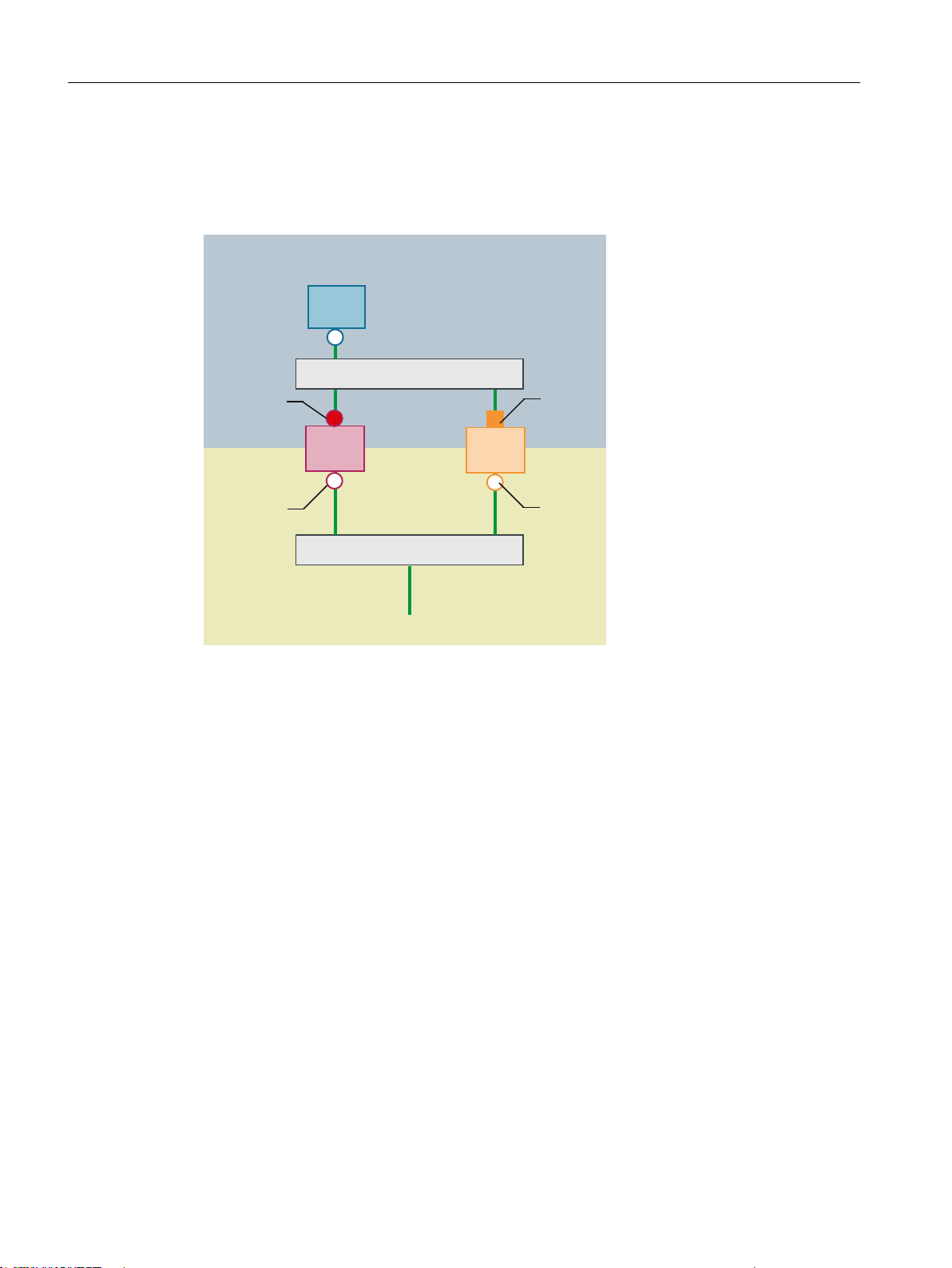
6ZLWFK
1&8
7&8
3&8
6\VWHPQHWZRUN
&RPSDQ\QHWZRUN
6ZLWFK
;
(WK
;
(WK
General information and networking
1.4 Networking
Configuration 5: PCU with TCU on NCU
Description
In this configuration, a switch is also required for the system network. All components are
connected using straight Ethernet cables.
In terms of address allocation and the settings that need to be made, this configuration is
identical to that of configuration 4. However, in this case, the DHCP server of the NCU actually
supplies the TCU with an IP address and serves as a boot server for the TCU.
The observations made for configuration 3 also apply here in relation to the connection to the
company network. The connection to a switch on the company network is made via a straight
Ethernet cable.
To connect one TCU to both HMI systems you must create an additional connection to the
NCU for the TCU, as described in the following chapter:
Operator panel front: OP 012
82 Manual, 09/2016, A5E36371591B
Page 83
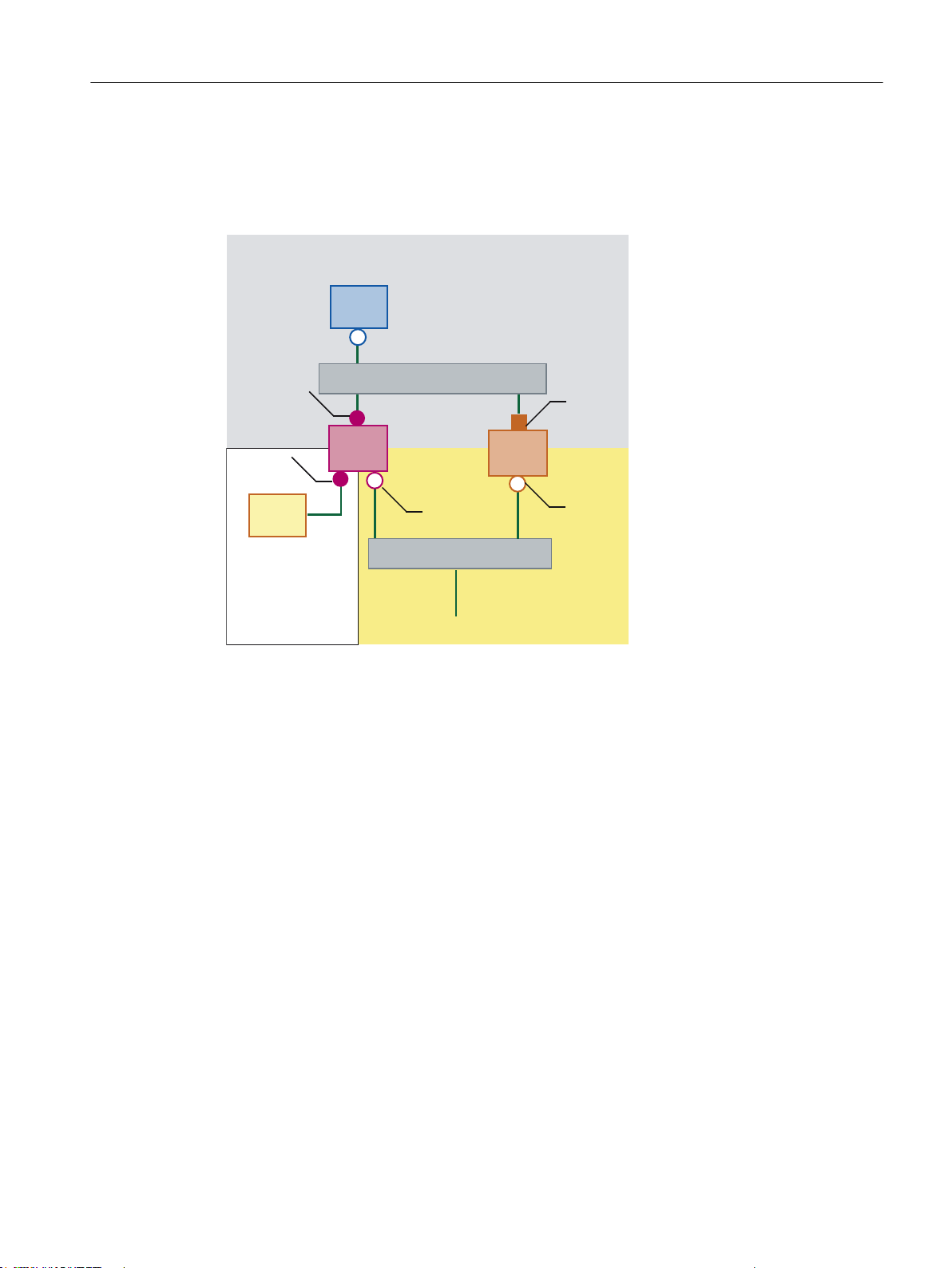
Connecting the programming device (PG) to the NCU
)LUPHQQHW]
$QODJHQQHW]
1&8
6ZLWFK
;
;
7&8
;
3*
6ZLWFK
3&8
(WK
(WK
Description
General information and networking
1.4 Networking
For service purposes a programming device is connected to the NCU at X127 as a standard
DHCP client (automatically obtain an IP address). An NCU is a standard DHCP server on
X127. On X127, the NCU occupies the fixed IP address 192.168.215.1 with the subnet mask
255.255.255.224.
At X127, IP addresses from 192.168.215.2 onwards are assigned via DHCP; e.g. to connect
a programming device. This is the reason that a fixed IP address must not be set at the
programming device.
1.4.3.4 Example: Configuring a VNC connection to a PC
Requirements
In order to use a TCU to get visual access to a computer from a SINUMERIK system via VNC,
the following requirements apply:
● The boot server (active DHCP server) in the system network must be an NCU.
● This NCU must be integrated via X130 or X120 into the network to which the computer to
be monitored is connected.
Operator panel front: OP 012
Manual, 09/2016, A5E36371591B 83
Page 84
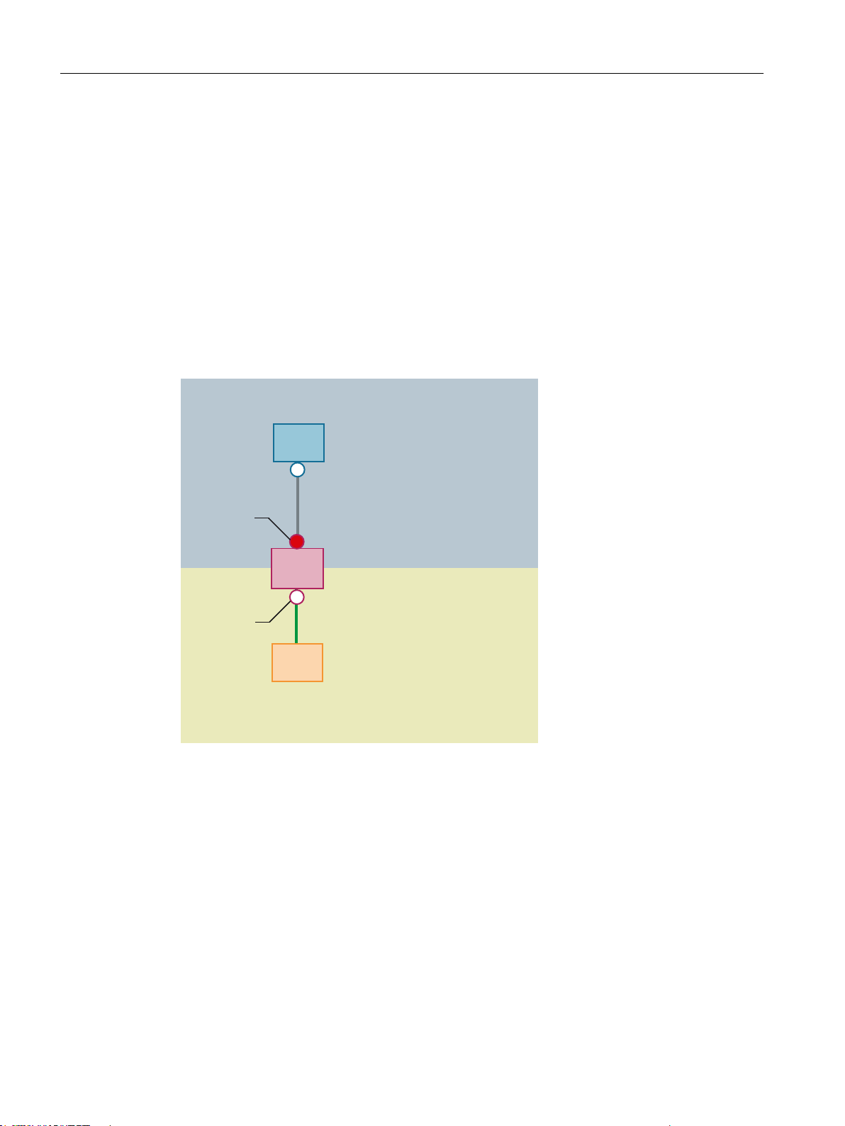
1&8
7&8
6\VWHPQHWZRUN
1HWZRUN
3*3&
;
;
General information and networking
1.4 Networking
● The computer to be monitored must be configured in the config.ini configuration file of the
TCU according to the general configuration for a TCU in a separate host section as a
switchover target for this TCU.
Where necessary, a password has to be specified in the configuration, if the VNC server
requires one on the target system (see below).
● To ensure that the TCU recognizes the new switchover target, the TCU requires a restart
and reboot.
● The screen resolution of the computer to be monitored must be adjusted to the conditions
of the TCU, since otherwise the TCU scales the image received to its possible range of
representation, which would adversely affect the representation on the TCU.
Configuration
Figure 1-25 Configuration example
Configuration
The config.ini file is located in the following directory:
NCU: /user/common/tcu/<TCU name>/common/tcu
PCU (Windows XP): F:\user_base\common\tcu\<TCU name>\common\tcu
PCU (Windows 7): C:\ProgramData\Siemens\MotionControl\user\common
\tcu\<TCU name>\common\tcu
The config.ini file must be stored on the boot server (active DHCP).
Example:
Operator panel front: OP 012
84 Manual, 09/2016, A5E36371591B
Page 85

[Station]
maxhostindex=2 /* Number of nodes that are defined under
[host_1] and [host_2].
mcpIndex=192
tcuIndex=1
eksIndex=0
[host_1]
Address=192.168.214.1 /* Address of the NCU to which the
connection is established during booting.
[host_2]
Address=157.163.230.202 /* Address of the PC
password=123456 /* Password of the VNC server on the PC
Switching over between the nodes
General information and networking
1.4 Networking
With the "Menu back" + MENU SELECT keys, the following actions are triggered:
● In the header of the displayed window you will see the TCU name, for example TCU1.
● A selection list for connecting to the other nodes will be displayed on the TCU.
See also
Settings in the "config.ini" file (Page 64)
1.4.3.5 Application example
Application
The configuration is suitable for the following application: Machine with concurrent operating
option to two operator panels , a full-featured operating panel with PCU and an operator panel
reduced to tool management.
Parallel operation of HMI-Advanced or SINUMERIK Operate on the PCU 50.3 and
SINUMERIK Operate as component of the CNC software on the SINUMERIK 840D sl NCU:
Any OP connected to PCU 50.3 and any OP connected to the NCU can be simultaneously
operated: in the example, OP 08T.
Operator panel front: OP 012
Manual, 09/2016, A5E36371591B 85
Page 86
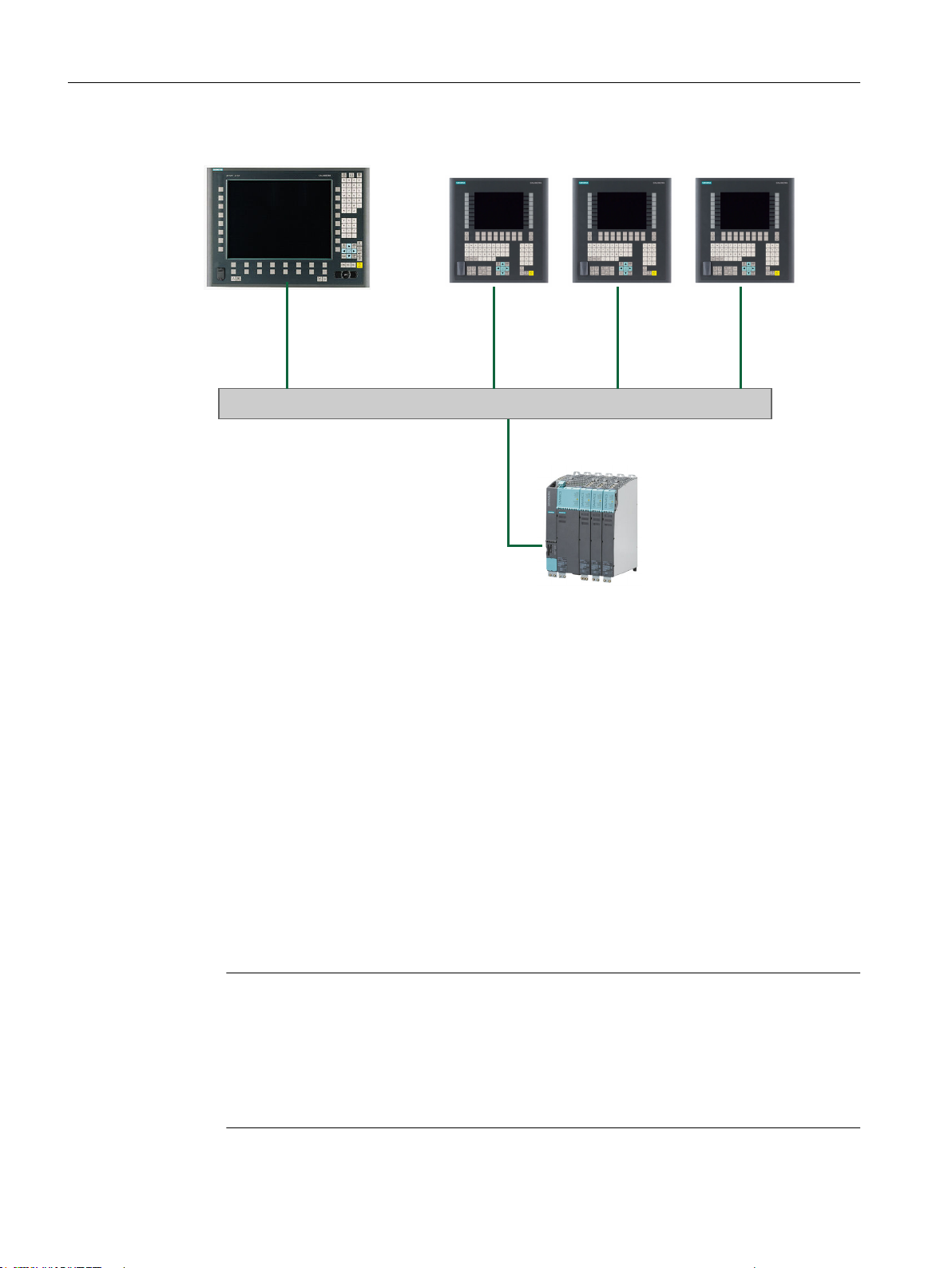
6\VWHPQHWZRUN
6ZLWFK
6,180(5,.'VO
3&8237237237
General information and networking
1.4 Networking
Figure 1-26 Configuration example
Proceed as follows
To configure the application example, proceed as follows:
1. PCU 50.3 with HMI Advanced
Deactivate the DHCP server on the PCU: For this select the option "Boot support runtime
and configuration only (TFTP/FTP)" on the "TCU support" tab of the "System Network
Center" program.
2. SINUMERIK 840D sl from CNC software, version 2.4 and higher
The systemconfiguration.ini configuration file is included on the SINUMERIK 840D
sl product DVD.
3. OP 08T operator panel
Once the installation of the OP 08T operator panel with SINUMERIK Operate has been
completed, copy the systemconfiguration.ini file from the /Siemens/
sinumerik/hmi/appl/systemconfig/tm/ directory to the /oem/sinumerik/hmi/
cfg/ directory. After this, a system restart is necessary.
Note
Subsequent changes
Once the file has been copied, no further settings (e.g. changing language) can be
implemented on the SINUMERIK Operate. If you want or need to implement changes later,
the systemconfiguration.ini file can be renamed (e.g., as systemconfiguration.save). After
this, a system restart is necessary. Following the restart, the full functional scope of
SINUMERIK Operate is available once again.
Operator panel front: OP 012
86 Manual, 09/2016, A5E36371591B
Page 87

1.4.4 Service and diagnostics
Thin Client Boot loader V04.50.11.00
IP address
<1/F1> diagnosis window
1.4.4.1 Booting of the TCU
Messages when booting
While the TCU is booting, progress is displayed after the BIOS has booted and before the
operating system is loaded. In addition to messages, the current booting status is also indicated
by a progress bar. While the IP address is being determined via DHCP and the TFTP is being
downloaded (boot image), a progress bar indicates that booting of the TCU is not yet complete,
or that a fault has occurred.
The structure of these messages is shown below:
General information and networking
1.4 Networking
You can see the current boot phase in the third line. Below that you are told whether you can
call up information via <F1> if a fault occurs.
Diagnostics options during booting
In the following cases, the diagnostics window is displayed and booting of the TCU is
interrupted:
● When the <1 / F1> function is selected during booting
● When a warning message is displayed
● When a fault occurs
Note
You can select the <1 / F1> to <F8> functions shown below using the horizontal softkeys
on the OP. For example, to select <F7>, press the horizontal softkey 7.
Press the appropriate key <1> for <F1> at an HT8.
Operator panel front: OP 012
Manual, 09/2016, A5E36371591B 87
Page 88
7hin Client Boot loader
Boot progress:
BIOS
MAC address
Hardware ID
Network link
IP add ress
Netmask
Boot server
Image metadata
Image version
Linux image (linux.bin)
Booting
<1/F1>details <7/F7>continue <8/F8>reboot
V04.05.11.00
V03.0 4.00.00
08:06:00:F1:F7:F8
7.7.0.0
1000MB, full duplex
192.168.214.1
255.255.255.0
192.168.214.1
98 bytes
V04.50.11.0 0
3295436 bytes
ready
General information and networking
1.4 Networking
Calling up the diagnostics window with <1 / F1>
Press <1 / F1> to continue
Key / text Meaning
F1 details Display detailed information
F7 continue Continue booting of the TCU
F8 reboot Restart the TCU
If you select function <F1> in the diagnostics window, the, detailed diagnostic information is
output.
Key / text Meaning
F1 ... F6 Navigate within the window
(alternatively, the relevant keys on the OP can be used).
F7 + Display more information
F8 - Display less information
F9 back Return to diagnostics window
88 Manual, 09/2016, A5E36371591B
Operator panel front: OP 012
Page 89

Description
Validity
Features
2
The SINUMERIK OP 012 operator panel front and 12.1" TFT color display with a resolution of
800 x 600 pixels (SVGA) features a 59-key membrane keyboard as well as 2 x (8 + 2) horizontal
and 2 x 8 vertical softkeys. The 2 x 8 vertical softkeys can be used as direct keys.
It is fixed from the rear using special clamps that are included in the delivery scope.
The description below applies to the OP 012 operator panel front.
Article number: 6FC5203-0AF02-0AA2
● 19" mounting format, 7 HU (height units)
● Panel cutout (W x H): 450 x 290 mm
● Limited mounting depth
● 12.1" TFT flat screen (color) with SVGA resolution 800 x 600 pixels
● Membrane keyboard with alphabetic, numeric, cursor, and control keypad
● Softkeys / direct keys:
– 2 x 8 horizontal rows of keys with softkey function
– 2 x 8 vertical rows of keys with softkey and direct key functions
– Direct keys connectable via direct key / handwheel connection module or MCP interface
PN (optional), machine control panel, TCU or directly to the I/Os
● Shift key for switchover to the second key level (not for switching over the letters, since
they are uppercase only)
● Integrated touchpad mouse
● Front USB interface
● Degree of protection IP65
● Attachment: Tension jacks at the rear
● Can be combined with PCU, TCU
Operator panel front: OP 012
Manual, 09/2016, A5E36371591B 89
Page 90

Description
Operator panel front: OP 012
90 Manual, 09/2016, A5E36371591B
Page 91
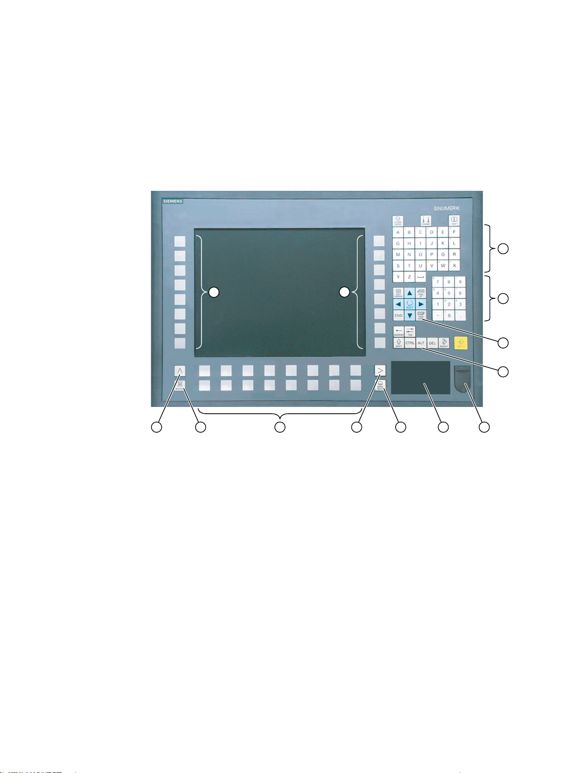
Operator control and display elements
3.1 View
3
① Alphabetic key group
② Numeric key group
③ Cursor key group
④ Control key group
⑤ Front USB interface
⑥ Touchpad mouse
⑦ Menu select key
⑧ Menu forward key
⑨ Horizontal softkeys
⑩ Machine area button
⑪ Menu back key
⑫ Vertical softkeys (direct keys)
Figure 3-1 Front view of operator panel front OP 012
Operator panel front: OP 012
Manual, 09/2016, A5E36371591B 91
Page 92
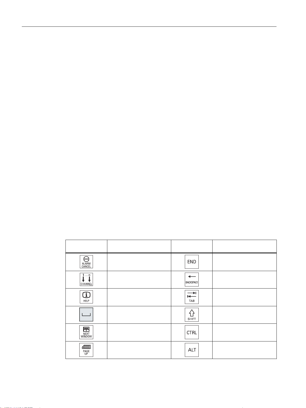
Operator control and display elements
3.2 Keyboard
3.2 Keyboard
Keyboard
Several keys and keypads are installed on the operator panel front:
● The alphabetic block contains the letters A - Z and the space character.
● The numeric block contains the digits 0 - 9, and the characters "-", "/", "=", "+" and ".".
● The cursor key group is used to navigate on the screen.
● The control key group includes special functions.
● The mouse comprises a touchpad, for finger operation, as well as for cursor navigation and
also for the left and right mouse buttons.
● The softkeys call up functions that are available on the screen via a menu bar.
● The "Menu back" key switches back to the higher-level horizontal menu.
● The "Menu forward" key advances in the extended horizontal softkey bar.
● The "Menu select" key calls the main menu to select the operating area.
● The "Machine area" key selects the "Machine" operating area.
Switching between upper and lower case
To toggle between upper and lower case letters, press the key combination Ctrl + Shift
Upper case is always activated as standard.
Overview of the key symbols
The key symbols used on the operator panel front are shown in the overview along with the
corresponding function keys on the PC keyboard.
Key Function corresponds to the
PC key function
Esc End
F11 Backspace
F12 Tab
Space (only intended for internal key‐
Key Function corresponds to the
PC key function
board changeover)
Home Ctrl key
Page up Alt key
Operator panel front: OP 012
92 Manual, 09/2016, A5E36371591B
Page 93
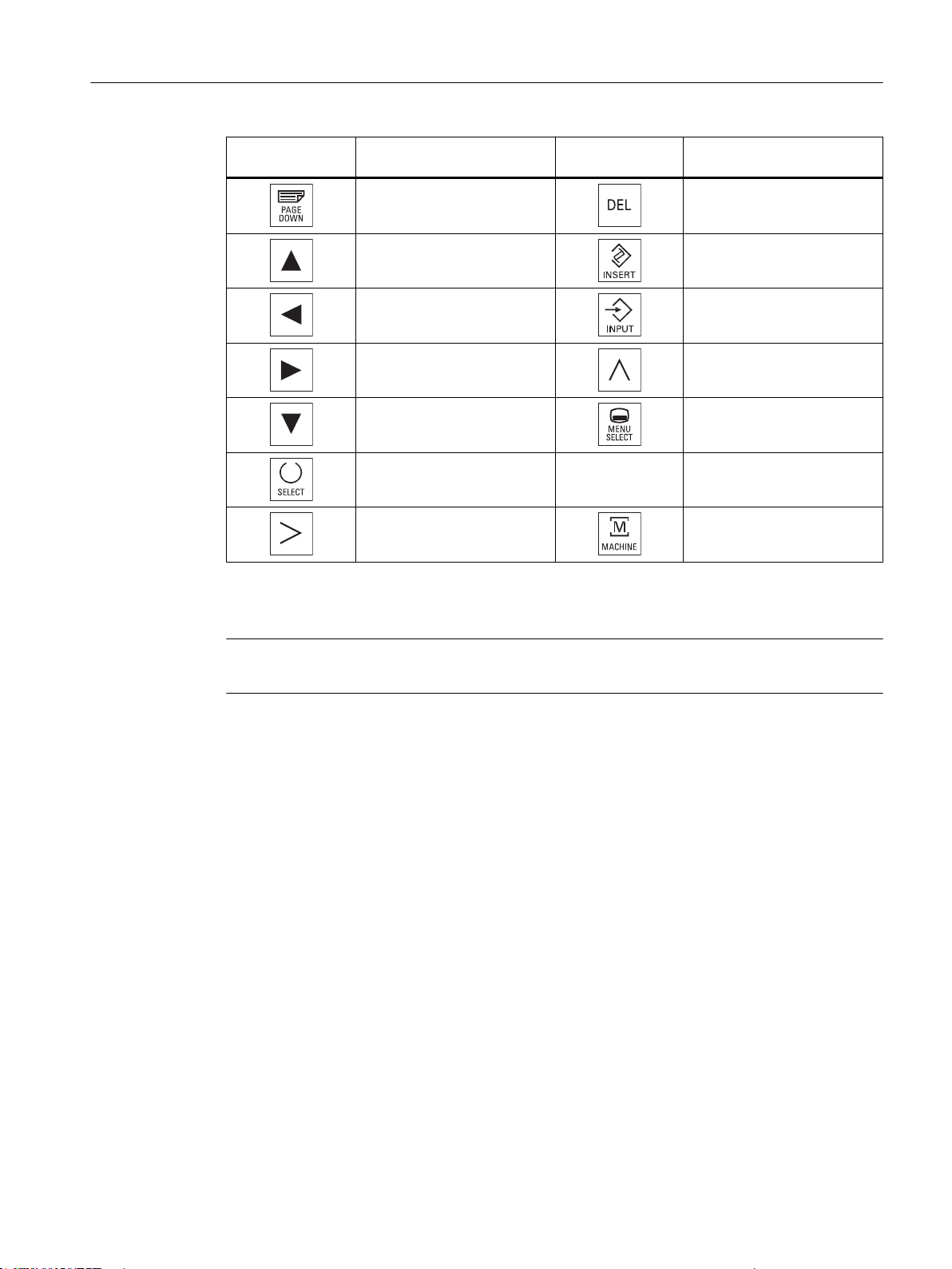
Operator control and display elements
3.3 Screen saver
Display
Key Function corresponds to the
PC key function
Page down Delete
Cursor up Insert
Cursor left Enter
Cursor right F9
Cursor down F10
5 (in numeric key group) A, ..., Z <Shift> A, ..., Z
<Shift> F9 <Shift> F10
Key Function corresponds to the
PC key function
Note
Pixel error according to DIN EN ISO 9241-307, Error class II.
3.3 Screen saver
If a screen with high contrast is displayed unchanged for longer than an hour, then the
screensaver must be activated in order to protect the TFT display against so-called "burning
in" of the last displayed screen.
The time can be adapted individually. Further information can be found at:
Commissioning of Basic Software and Operating Software, SINUMERIK Operate (IM9)
Operator panel front: OP 012
Manual, 09/2016, A5E36371591B 93
Page 94

Operator control and display elements
3.4 Touchpad mouse
3.4 Touchpad mouse
Operation
All of the mouse functions are based on 2-finger operation. The principle of operation of the
OP 012 touchpad mouse is explained in the following table with reference to a classic 2-key
mouse.
Action Touch event Corresponds to
Move the mouse pointer Place your finger on the touchpad, keep it
in position and then move it.
Select Touch the touchpad once with your finger. Click with the left mouse button
Execute Touch the touchpad twice with your finger. Double-click with left mouse button.
Drag, mark, move window Touch the touchpad twice in succession,
keep finger in position and then move.
Open the context menu Touch the touchpad with two fingers, keep
briefly in place then lift one finger.
Note
Move the mouse.
Click with the left mouse button and drag the
mouse.
Click with the right mouse button.
The touchpad cannot be used in environments with spray water or water jets. Operating the
touchpad in environments with dripping water is only possible with some restrictions.
Operator panel front: OP 012
94 Manual, 09/2016, A5E36371591B
Page 95

Interfaces
Front
Rear
4
USB 1.1 Full Speed (12 Mbit/s), high power (500 mA), Type A connector for connecting an
external keyboard, mouse and USB flash drive (see View (Page 91)).
Note
Note that the electromagnetic compatibility of commercially available peripheral devices
operated via the USB interface is usually rated for office use only.
For industrial use, components with a higher degree of certification are recommended.
● Two flat ribbon cables for connecting the PCU:
– I/O USB cable K1 (ribbon cable): all signals that are used for the display interface and
the connection of operator panel fronts
(e.g. supply voltages).
– Display cable K2
● Direct key interface X11 (under the cover plate); signals from the 16 "vertical softkey" direct
keys
● Interface X12 - reserved (under the cover plate)
Operator panel front: OP 012
Manual, 09/2016, A5E36371591B 95
Page 96
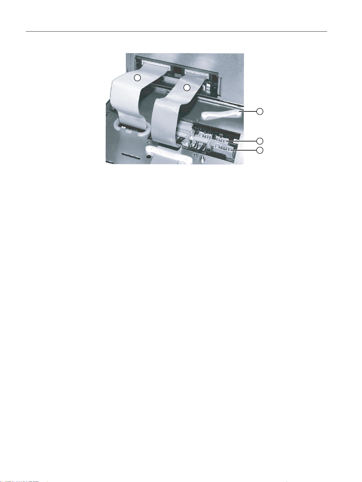
3&8
23
Interfaces
① I/O USB cable K1
② Display cable K2
③ Retainer for the connecting cable for the direct key module
④ Direct key interface X11
⑤ Interface X12 (reserved)
Pin assignment
Figure 4-1 Connections on rear of housing: Connections to the PCU
For more detailed information, see "General information and networking", Chapter:
"Connecting".
96 Manual, 09/2016, A5E36371591B
Operator panel front: OP 012
Page 97
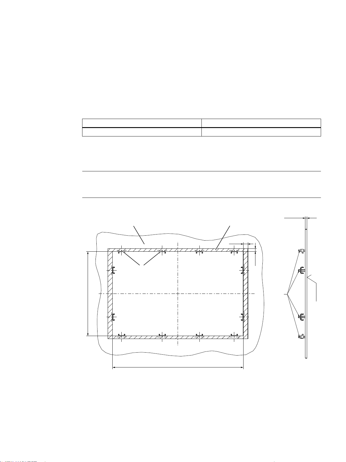
Installation
3UHVVXUHSRLQWV
IRUWHQVLRQMDFNV
6HDOLQJDUHD
7HQVLRQMDFNVZLWKVHWVFUHZV
0RXQWLQJSDQHO
,QWKHVHDOLQJDUHD
5]
s
s
5.1 Preparation for mounting
Table 5-1 Dimensions of the mounting opening
Width (mm) Height (mm)
450 290
Thanks to the tension jacks on the OP 012, drill-holes or screw holes are not needed.
This retaining method also enables the IP65 degree of protection (but only in conjunction with
a circumferential seal and when the protective USB cap is fitted).
Note
The OP 012 is supplied with what are known as "small" tension jacks. If you have the "large"
tension jacks (6FC5248-0AF06-0AA0) in stock, then you can also use these.
5
Figure 5-1 Dimension sheet for installing the OP 012 operator panel front
Operator panel front: OP 012
Manual, 09/2016, A5E36371591B 97
Page 98
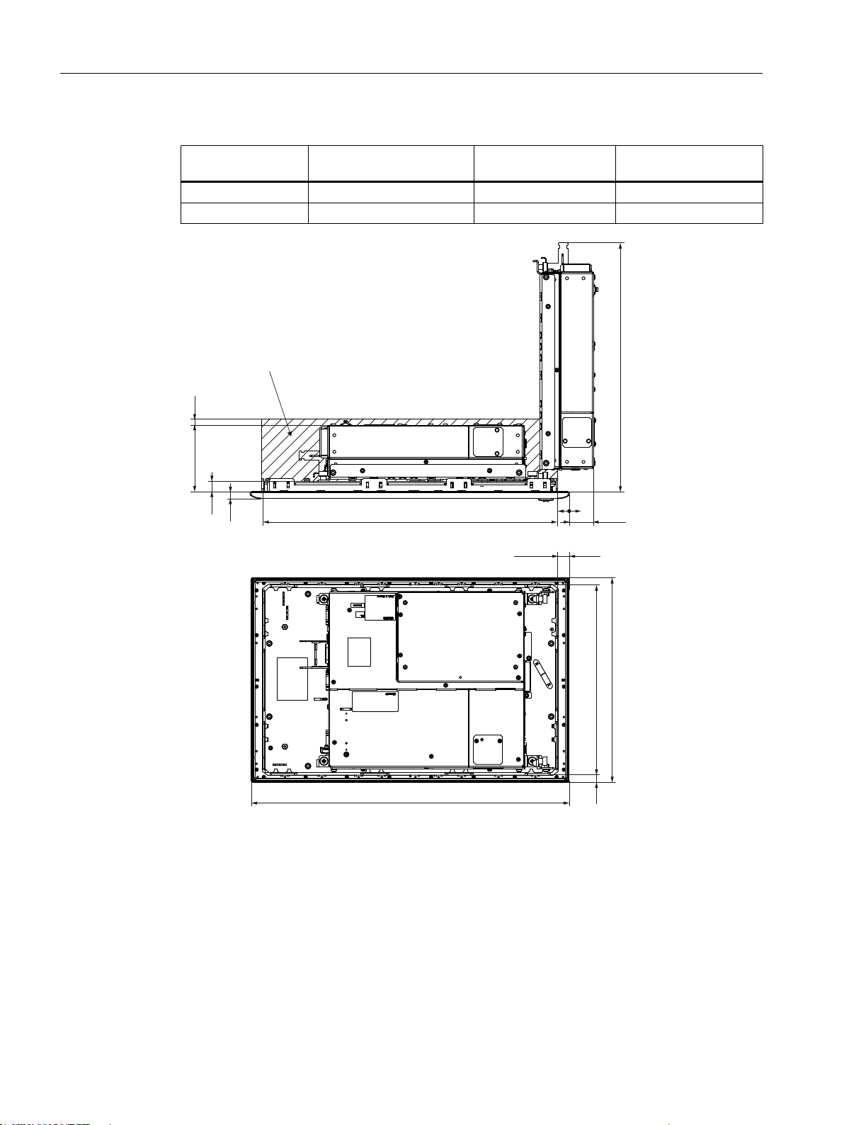
&OHDUDQFHIRUFDEOHVDQGYHQWLODWLRQ
3&8LQWKHHQGSRVLWLRQ
3&8VZLYHOHGRXWE\r
s
7s
s
s
7s
Installation
5.2 Assembling an OP 012 and a PCU
Table 5-2 Dimensions to be observed when installing
Mounting depth T3 + clear‐
ance (mm)
Opening depth T5
(mm)
Protrusion P
(mm)
PCU 50.5 101 + 10 377 39
TCU x0.2 50 + 10 350 -12
5.2 Assembling an OP 012 and a PCU
98 Manual, 09/2016, A5E36371591B
Figure 5-2 Dimension sheet for attaching the PCU to the OP 012 operator panel front
When combining an OP 012 and PCU and possibly a direct key module, it is advisable to
assemble them prior to installation in an assembly panel.
Operator panel front: OP 012
Page 99
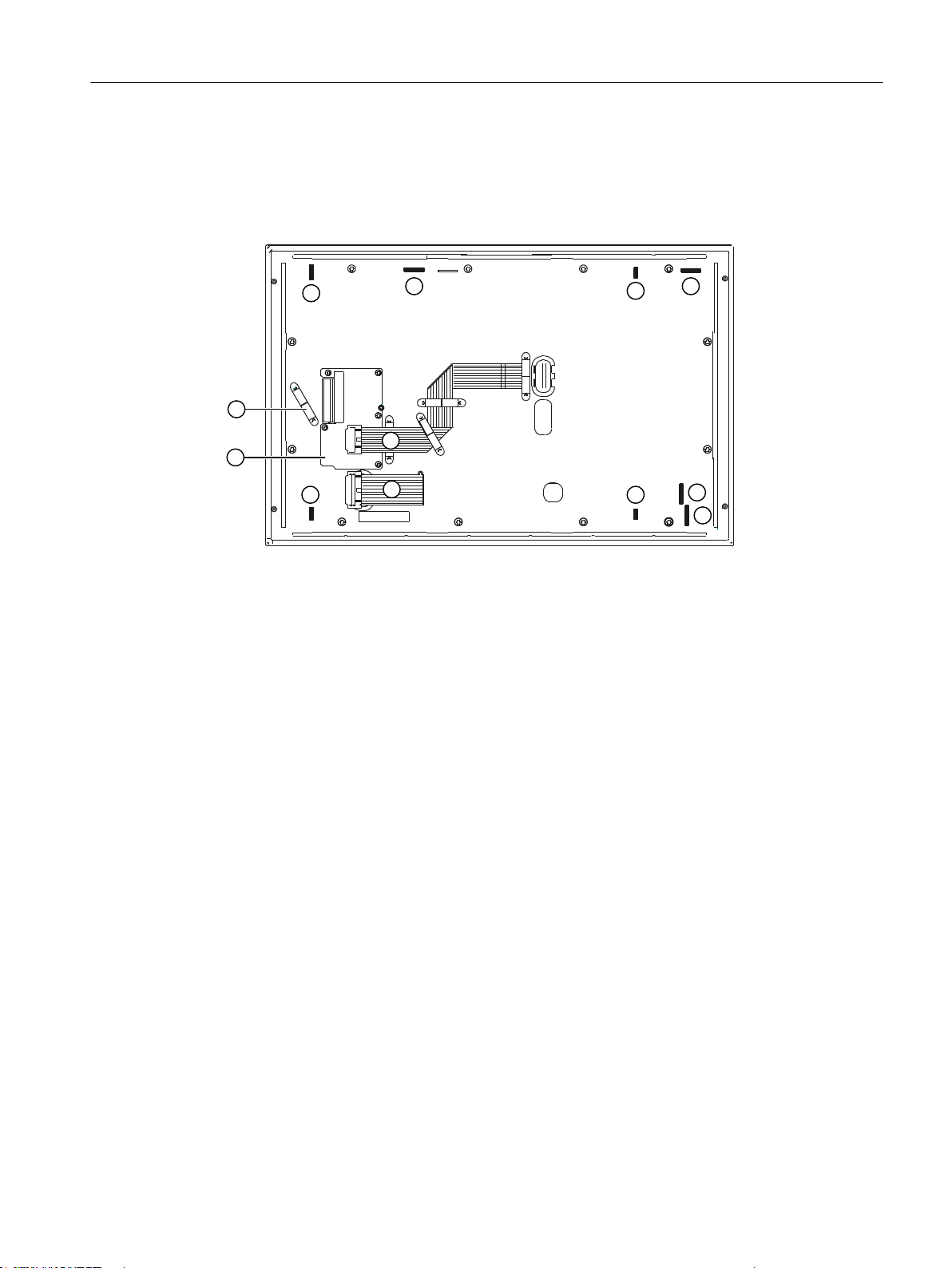
Requirement
Installation
5.2 Assembling an OP 012 and a PCU
The PCU must now be bolted to the mounting brackets prior to assembly (if this has not already
been done). See Section in the “PCU 50.5” manual under “Assembly" → "Assembly of PCU
and operator panel front (standard mounting)"
Procedure
① Mounting slots for PCU lugs
② Slots for inserting softkey labeling strips
③ I/O USB cable K1
④ Display cable K2
⑤ Cover plate for keyboard controller connections
⑤ Retainers
Figure 5-3 Rear of the OP 012
1. Place the OP 012 face down on a flat, soft (to avoid scratches) surface.
– Installation of the direct key module (see section in the “Direct key module" manual
under "installation" → “Combination with OP 012")
– Install or replace the softkey labeling strips (see Softkey labeling (Page 102))
2. Remove the PCU's interface cover.
3. Place the PCU with the lugs of the bolted-on mounting brackets into the mounting slots on
the OP 012 as shown by the white arrows in diagram (A).
To make it easier to insert the lugs, it can be helpful to reduce the 90° angle between the
PCU and OP 012 by tilting the PCU as shown by the black arrow in the picture.
4. Insert cables K1 ① and K2 ② of the OP 012 in the connector strips of the PCU [see the
gray arrows in the diagram (A)]. Make sure that the connectors lock in audibly and that the
locks [see arrows in diagram: (B)] are closed.
5. Swivel the PCU into its final position and secure it with knurled screws, tightening torque
of 1.8 Nm [see diagram: (C)].
Operator panel front: OP 012
Manual, 09/2016, A5E36371591B 99
Page 100
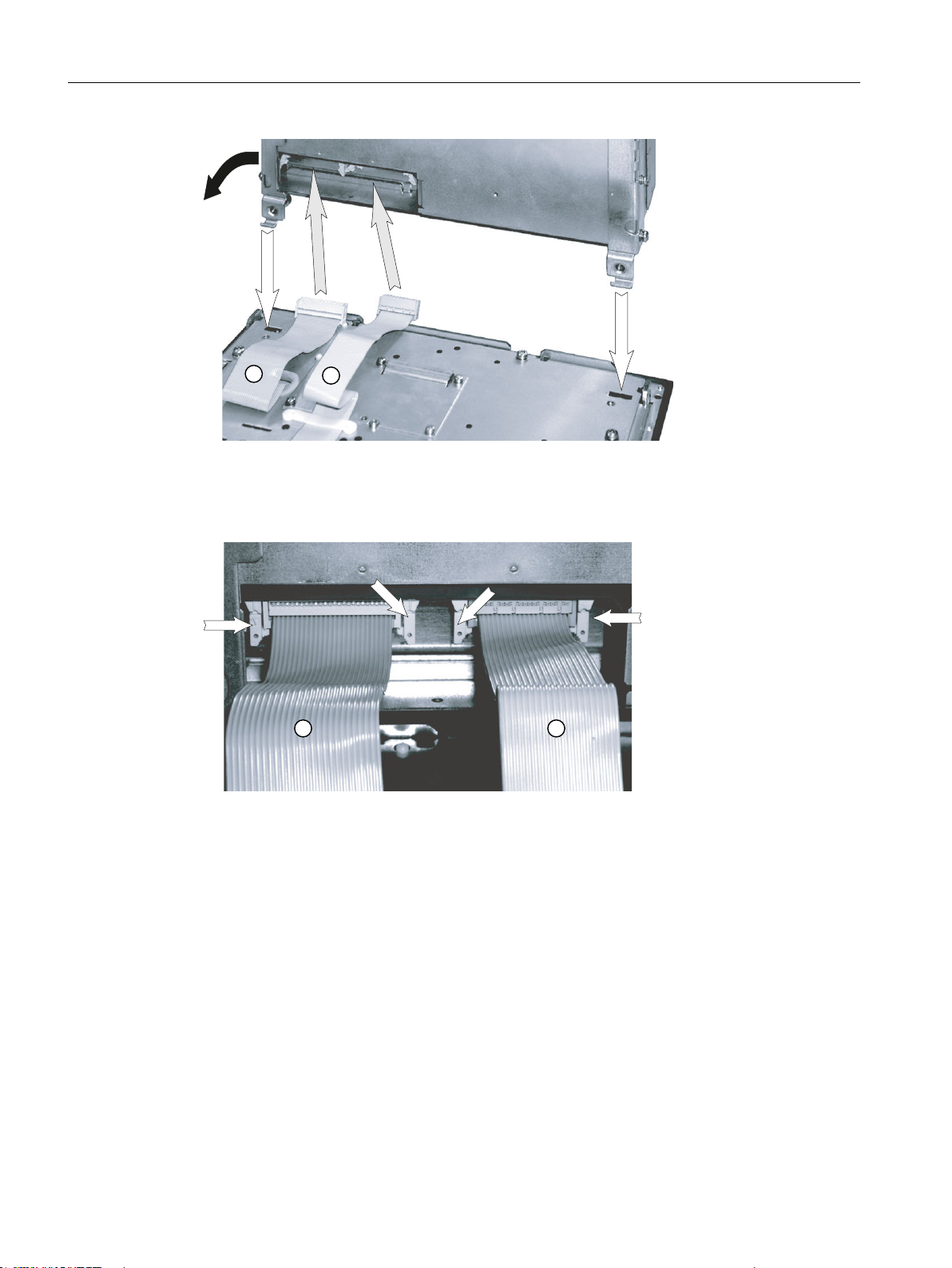
3&8
23
3&8
Installation
5.2 Assembling an OP 012 and a PCU
① I/O USB cable K1
② Display cable K2
Figure 5-4 (A) Assembling PCU and OP 012
① I/O / USB cable K1
② Display cable K2
Figure 5-5 (B) Correct connection of I/O-USB and display cables to the PCU
100 Manual, 09/2016, A5E36371591B
Operator panel front: OP 012
 Loading...