

Installation instructions
Instructions for use
EN
Notice de montage et d'installation
Notice d'utilisation
HSL6EI23
HSL6EW22
FR

...........

Installation instructions 2 - 15
Instructions for use 16 - 43
EN
Notice de montage et d'installation 44 - 58
Notice d'utilisation 59 - 88
FR
1

Installation instructions 2-15 | Instructions for use 16-43
Installation instructions
Safety information____________________________________________3
Before installation____________________________________________ 4
Appliance........................................................................................................ 4
Ventilation area guidelines ............................................................................. 6
Electric connection ___________________________________________ 7
Gas connection ______________________________________________ 9
Installing and dismantling the appliance ________________________ 13
Converting the gas type ______________________________________ 14
Oven burner ................................................................................................. 14
General nozzle table .................................................................................... 15
2

Safety information
The safe operation of this appliance can only be
guaranteed if it has been assembled and installed by
a professional in accordance with these instructions.
The fitter and/or installer is liable for any damage or
faults resulting from incorrect assembly or
installation.
All installation work and adjustments, and any
conversion to a different type of gas, must be carried
out by an authorised expert in accordance with the
applicable rules and regulations enforced by the local
gas suppliers.
Always disconnect the gas supply before carrying out
any work on the appliance.
Prior to installation of the appliance, verify that the
local prerequisites (gas type and gas pressure) and
the appliance settings are compatible with one
another. The rating plate indicates the appliance
adjustment conditions.
3
Before installation
Note the following appliance specifications and the
guidelines relating to the ventilation area.
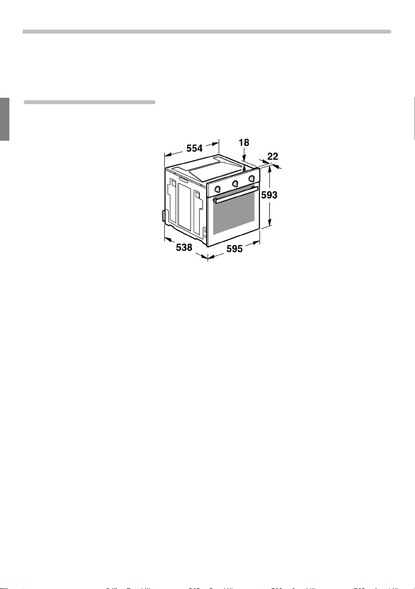
Appliance
Appliance dimensions Note the specified dimensions.
Installation positions This appliance can be fitted in the following positions:
• Underneath a worktop
• Above another appliance
4
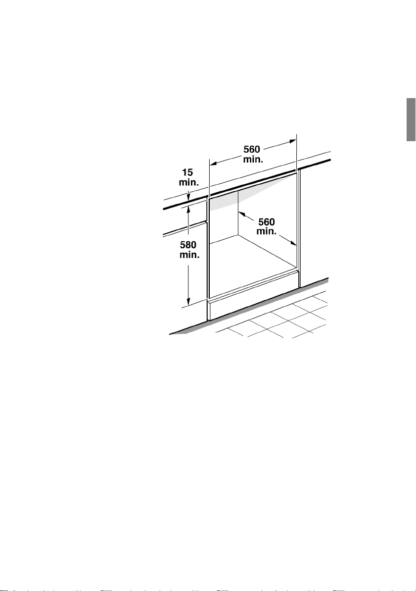
Adjacent units Adjacent units must be made from non-combustible
materials. The fronts of adjacent units must be heatresistant up to at least 120°C.
Coat cut surfaces with specialist water-resistant glue.
If the appliance is to be installed close to other units,
you must observe the specified minimum clearance
distances:
5
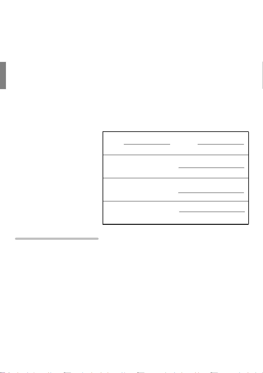
Rating plate The technical data for the appliance can be found on
the rating plate on the back of the appliance and on
the left-hand side of the cooking compartment when
the appliance door is open. Never remove the rating
plate from the appliance.
The setting values are specified on the rating plate on
the rear right of the appliance.
In the table below, enter the
product number (E no.),
production number (FD no.),
factory settings for gas type and gas pressure and,
if applicable, the converted gas type and gas
pressure.
E no. FD no.
After-sales service
Gas type
Gas pressure
(factory setting)
Gas type
Gas pressure
(conversion)
Ventilation area guidelines
This appliance may only be installed in a room with
adequate ventilation, and in accordance with the
applicable regulations and ventilation requirements.
This appliance is not connected to a smoke extraction
system. Install the appliance in a position where
natural or routed ventilation can be ensured by
means of openings to the outside or suitable air
pipes. The ventilation must ensure a continuous air
supply which is sufficient to provide the air required
for combustion and also expel expended air.
6

Electric connection
Only a licensed expert may connect the appliance.
The appliance must be installed in accordance with
the latest IEE guidelines (Institution of Electrical
Engineers). The appliance could be damaged if
incorrectly connected.
Make sure that the voltage value of the power supply
corresponds with the value specified on the rating
plate. The rating plate is located on the back of the
appliance. Ensure that the power supply is properly
earthed and that the wiring system in the building can
withstand the load from the appliance.
If the appliance is connected directly to the power
supply, an all-pin isolating switch must be present
with a contact gap of 3 mm.
The method of connection must allow complete
isolation in accordance with the conditions for
overvoltage category III. The earth cable is excluded
from this.
Install the mains cable in such a way that it is not
trapped or squashed. The cable must not come into
contact with cut or sharp edges.
7

Connecting the mains
cable
The mains cable is connected via the strip terminal.
The mains cable must be of the following type:
• H05RRF or H05RNF
• 3 x 1.5 mm²
• 220-240 V~
Proceed as follows:
• Open the terminal box on the back of the
appliance.
• On the strip terminal, loosen the screw which is
holding the cable in place.
• Loosen the screw contacts. The cable must
comply with the stipulated specifications and it
must be long enough.
• Connect the yellow/green wire to terminal $.
This wire must be at least 30 mm longer than the
other wires.
• Connect the blue neutral conductor to terminal N.
• Connect the brown cable to terminal L.
8
Gas connection
The appliance must be connected in accordance with
the currently applicable regulations.
Prior to installation of the appliance, verify that the
local prerequisites (gas type and gas pressure) and
the appliance settings are compatible with one
another. The rating plate indicates the appliance
adjustment conditions.
The appliance must be connected to the gas lines
and seals by a professional in accordance with
currently applicable standards.
Gas connection to the
appliance
The gas connection (ISO 228-1) is located at the rear
left of the appliance.
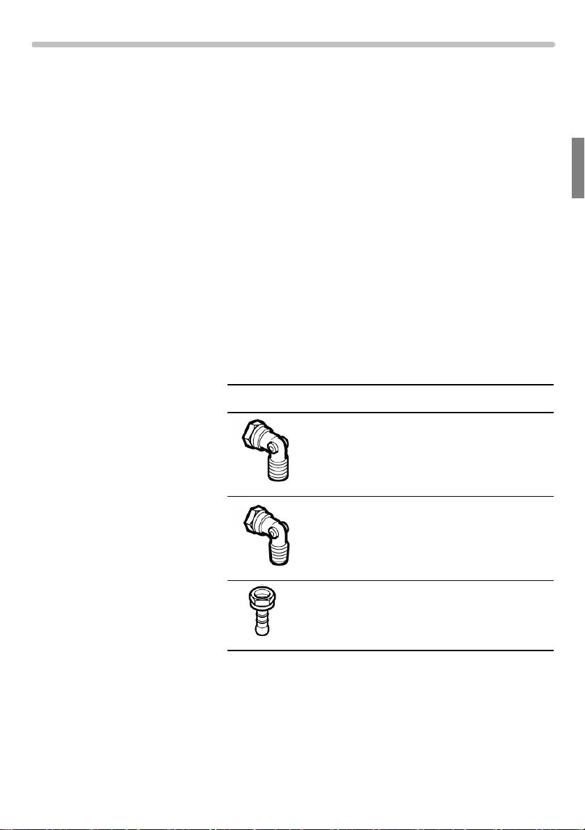
The following connections are provided with the
appliance:
Connection Description
ISO 228-1/ISO 228-1 angle
(and seal)
ISO 228-1/ISO 7-1 angle
(and seal)
ISO 228-1/LPG corrugated tube
nipple (and seal)
9
Country-specific
connection
ISO 228-1 +
corrugated tube
nipple
AE X X
AF X X
BD X X
BH X X
DZ X X
EG X X
GH X X
IR X X
JO X X
KW X X
LB X X
LY X X
MA X X
OM X X
PK X X
QA X X
SA X X
SD X X
SY X X
TN X X
YE X X
ISO 7-1
10
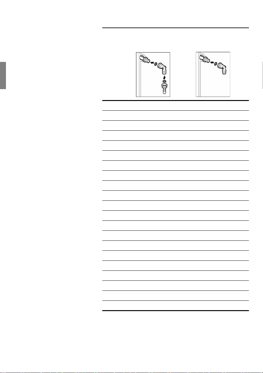
Connecting to natural gas Proceed as follows:
A
B
C
D
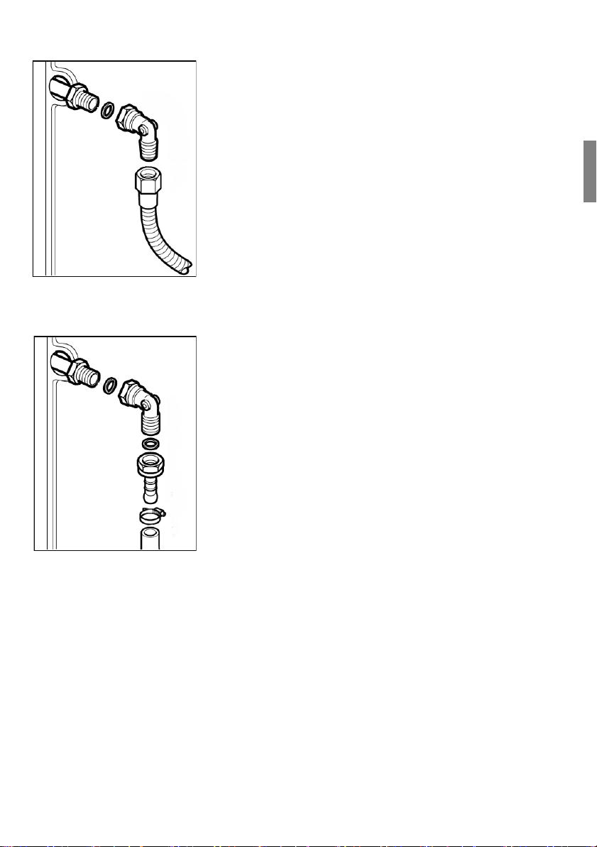
Connecting to liquefied gas Proceed as follows:
A
B
C
D
E
F
G
• Screw the connecting piece (C) and the seal (B)
to the gas connection (A).
• Hold the ISO 228-1/
in place with a spanner and screw the connecting
piece to a fixed supply pipe or a flexible gas
connecting hose (D).
Only use supply pipes or flexible hoses which
comply with the applicable regulations and which
are approved for this purpose.
Only use approved sealing compound to seal the
thread.
• Screw the ISO 228-1/
(C) and the seal (B) to the gas connection (A).
• Screw the corrugated tube nipple (E) and the seal
(D) to the connection angle (C+A).
• Hold the corrugated tube nipple (E) in place with
a spanner and screw the connecting piece to a
flexible gas connecting hose (G).
• Tighten the clamp (F).
Only use supply pipes or flexible hoses which
comply with the applicable regulations and which
are approved for this purpose.
Only use approved sealing compound to seal the
thread.
ISO 7-1
ISO 228-1
connection angle (C)
connection angle
11

Flexible hoses If you use flexible hoses, make sure that:
• the hoses are not trapped or squashed.
• no tractive or torsional forces are exerted on the
hoses.
• the hoses are not touching any cutting or sharp
edges, for example.
• the hoses are not touching any heated parts such
as the bottom, back or ceiling of the oven.
Make sure that the full length of the hoses is
accessible for inspection.
Safety valve It is mandatory to install a safety valve to allow the
gas supply to be opened and closed.
Install the safety valve between the gas supply line to
the relevant room and the appliance. Ensure that
there is unhindered access to this valve.
Testing for leaks Once the gas line is connected, check for leaks in the
connections using soapy water.
Initial use Switch the appliance on as described in the
instruction manual.
Light all the burners and check that the flames remain
stable at both the high and low settings.
12
Installing and dismantling the
appliance
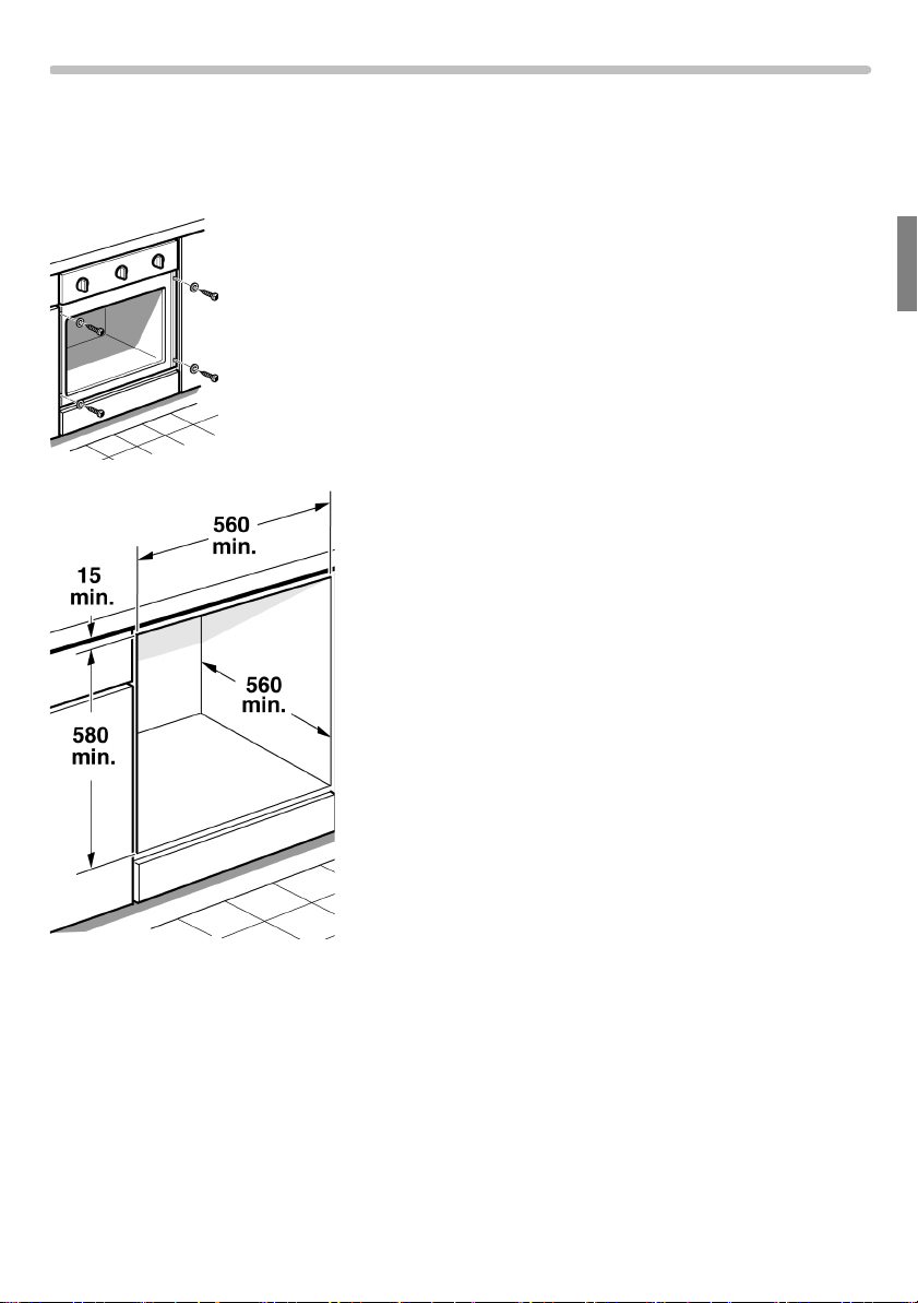
Installing the appliance Install the appliance as follows:
• Fully insert the appliance and centre it. Ensure
that no power cables or connecting cables are
kinked, trapped or running over sharp edges.
• Adjust the appliance so that it is horizontal,
bearing in mind that there must a gap of 15 mm
above the appliance.
• Screw the appliance to the cupboard with the
4 securing screws.
Dismantling the appliance Dismantle the appliance as follows:
• Disconnect the appliance from the power supply.
Switch off the gas supply.
• Undo the securing screws, lift the appliance
slightly and pull it out.
• If necessary, disconnect the electric and gas
connections in accordance with regulations.
13
Converting the gas type
If the appliance is not already set to use the type of
gas that is available, the appliance must be
converted.
Conversion to a different type of gas must be carried
out by an authorised expert and in accordance with
the applicable regulations.
The rating plate indicates the type of gas and the gas
pressure which have been pre-set in the factory.
In order to convert to a different type of gas, the
nozzles must be replaced and the low flame must be
adjusted.
Oven burner
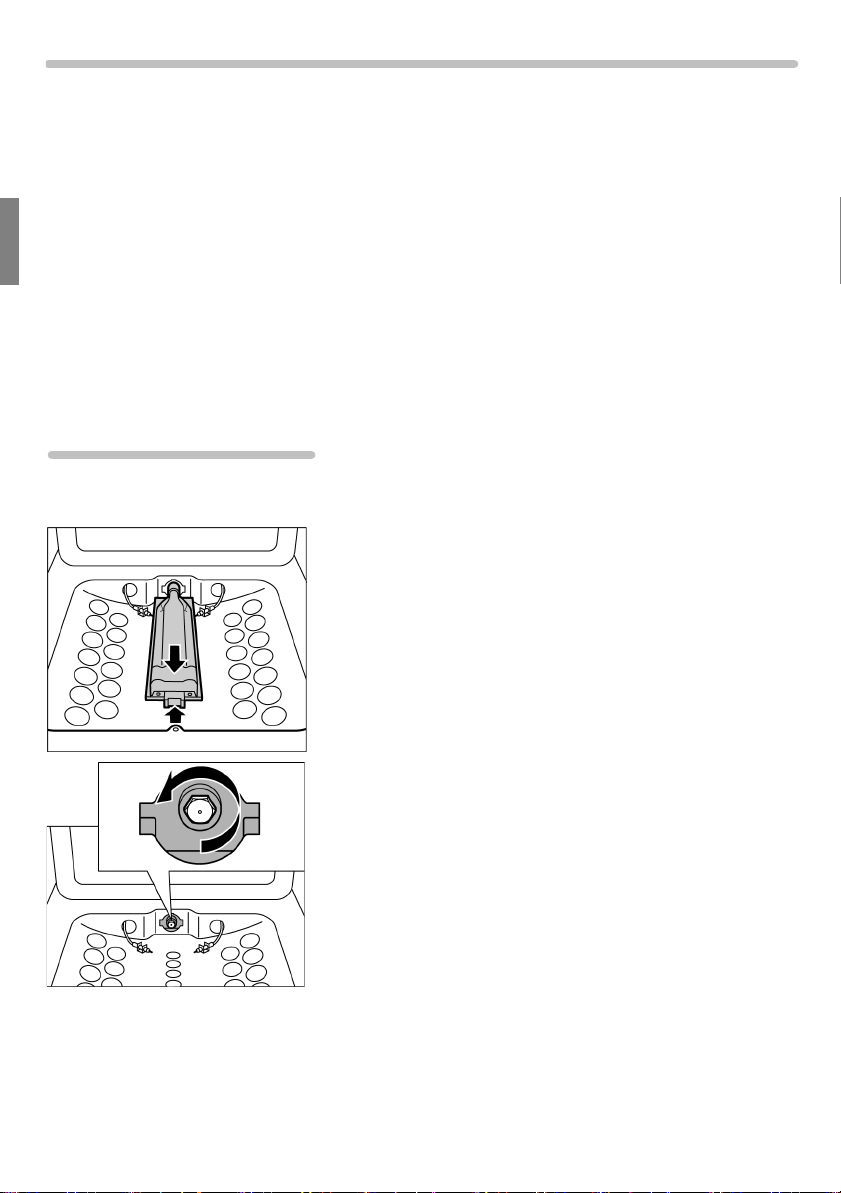
Replacing the nozzles Proceed as follows:
• Dismantle the shelf part of the oven.
• Loosen the screw on the front part of the oven
burner and pull it upwards slightly.
14
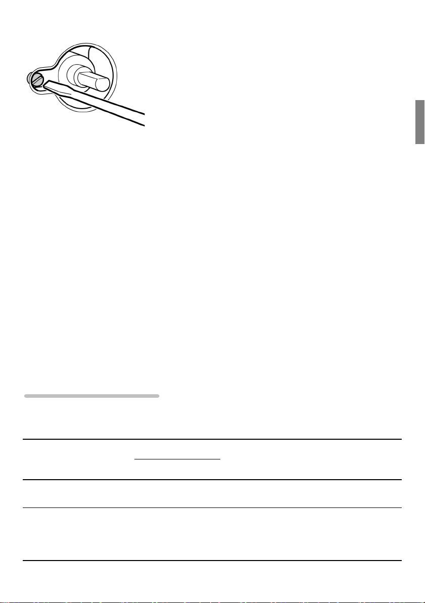
• Unscrew the nozzle and replace it with a nozzle
which is suitable for use with the new type of gas
(see "General nozzle table" section).
• To reassemble, follow the instructions in reverse
order.
Adjusting the low flame Proceed as follows:
• Open the appliance door. Press the control knob
for the oven in and turn it anti-clockwise to the
maximum setting
The gas burner will light. Hold the control knob
pressed in for around 15 seconds and then let go.
• Close the appliance door. Remove the control
knob.
• Through the gas tap opening in the control panel,
loosen the internal setting screw slightly.
• Replace the control knob and heat the oven for
15 minutes.
• Then turn the control knob to the minimum setting
160
.
• Remove the control knob again.
• Now, through the gas tap opening in the control
panel, adjust the internal setting screw until a
correct, stable flame is burning.
Loosen the setting screw to increase the gas flow
or tighten it to reduce the gas flow. The setting is
correct when the low flame is around 3 to 4 mm
high.
In the case of a connection to liquefied gas,
tighten the setting screw.
• Replace the control knob again.
• Make sure that the flame does not go out when
the gas flow is changed quickly from maximum to
minimum and vice versa, and when the appliance
door is opened and closed.
265
.
General nozzle table
Gas type mbar
Natural gas
G20 (E)
Liquefied gas
Butane
Propane
G30/G31
20 115 Partially
28-30/3775 0.48
Nozzle no.
open
Burner type Power
(W)
Oven burner
Oven burner
2,400 229 l/h
2,400 175 g/h
Max. consumptionNozzle Bypass
15

Instructions for use
Important information________________________________________17
Safety information........................................................................................18
Material damage...........................................................................................20
Your new appliance__________________________________________21
The control panel..........................................................................................21
The oven......................................................................................................22
The minute minder.......................................................................................24
Before using for the firs t time _______________ _____ ______ _____ __2 5
Baking out the oven......................................................................................25
Cleaning accessories...................................................................................25
Operating the oven__________________________________________26
Operating the oven gas burner.....................................................................26
Operating the grill.........................................................................................27
Using the rotary spit.....................................................................................28
Operating the minute minder__________________________________31
Cleaning and care___________________________________________31
Catalytic side panels....................................................................................31
Using the correct cleaning agent..................................................................32
Removing and fitting the appliance door......................................................33
Removing and inserting the hook-in racks...................................................35
Faults and after-sales service_________________________________37
After-sales service........................................................................................38
Replacing the oven light...............................................................................39
Tips and tricks______________________________________________40
Tips for saving energy..................................................................................40
Tips for using your appliance.......................................................................40
Baking................................................................................................41
Roasting.............................................................................................42
Grilling................................................................................................43
16

Important information
Please read this instruction manual carefully.
This will enable you to operate your appliance safely
and correctly.
Keep the instruction manual and the assembly
instructions, as well as the various accessories, in a
safe place. Please pass on these manuals and the
accessories to the new owner if you sell the
appliance.
Damage during transport Check the appliance for damage after unpacking it.
Do not connect the appliance if it has been damaged
in transport.
Environmentally-friendly
disposal
Gas connection All work involved in connecting the appliance to the
Dispose of packaging in an environmentally-friendly
manner.
This appliance is labelled in accordance with
European Directive 2002/96/EC on Waste Electrical
¦
and Electronic Equipment — WEEE.
gas supply and/or converting it to a different type of
gas must be carried out by a licensed expert.
Assembly instructions are provided with the
appliance.
Any damage arising from the appliance being
connected incorrectly will invalidate the guarantee.
Therefore, no liability will be accepted for damage
and faults caused by connection and setting errors.
17

m Safety information
This appliance is intended for domestic use only.
This appliance must only be used for food
preparation.
Neither adults nor children should operate the
appliance unsupervised
• if they are physically or mentally incapable of
doing so
• or if they lack the knowledge and experience
required to operate the appliance correctly and
safely.
Never let children play with the appliance.
Hot surfaces Risk of burns.
Never touch the hot surfaces of the cooking
compartment or the heating elements.
Children must always be kept at a safe distance from
the appliance.
Open the appliance door carefully. Hot steam may
escape.
Risk of fire.
Never place combustible items in the oven.
Risk of short-circuiting.
Never trap electrical appliance cables in the hot oven
door. The cable insulation could melt.
High-proof alcohol Be careful with food that is prepared using drinks with
a high alcohol content (e.g. cognac, rum).
Alcohol evaporates at high temperatures. In
unfavourable circumstances, the alcoholic vapours
could catch fire in the appliance.
Risk of burns.
Only use small quantities of drinks with a high alcohol
content and open the appliance door carefully.
18

Inadequate ventilation
when using gas burners
Repairs Risk of electric shock
Never use the gas burners in unventilated rooms.
Cooking with gas burners releases extra heat and
moisture.
Incorrect repairs are dangerous.
Repairs may only be carried out by one of our trained
after-sales engineers.
If the appliance is faulty, switch off the gas supply.
Call the after-sales service.
Faults in the gas
installation/smell of gas
Safety valve Close the safety valve on the gas supply line if the
If you notice a smell of gas or faults in the gas
installation, you must
• immediately switch off the gas supply and/or
close the gas cylinder valve
• immediately extinguish all naked flames and
cigarettes
• switch off electrical appliances and lights
• open windows and ventilate the room
• call the after-sales service or the gas supplier
appliance is going to be left unused for a long period
of time.
19

Material damage
Damage to the oven Never cook meals on the floor of the oven. Do not
place the baking tray on the oven floor. Do not cover
it with aluminium foil.
Do not place dishes on the oven floor. This will cause
heat accumulation. The baking and roasting times will
no longer be correct and the enamel will be damaged.
Never pour water directly into a hot oven. This will
damage the enamel.
When making very moist fruit flans, do not put too
much on the baking tray. Fruit juice dripping from the
baking tray leaves stains that cannot be removed.
Do not stand or sit on the open oven door.
Damage to the fronts of
adjacent units
Only leave the oven to cool down with the door
closed. The fronts of adjacent units may become
damaged over time even if you only leave the oven
door open slightly.
If the oven door seal is very dirty, the appliance door
will no longer close properly during operation. The
fronts of adjacent units will become damaged over
time. Keep the seal clean.
20
Your new appliance
This manual introduces you to the features of your
new appliance. It contains information about the
control panel as well as about the oven, the operating
modes and the included accessories.
Control panel
Oven
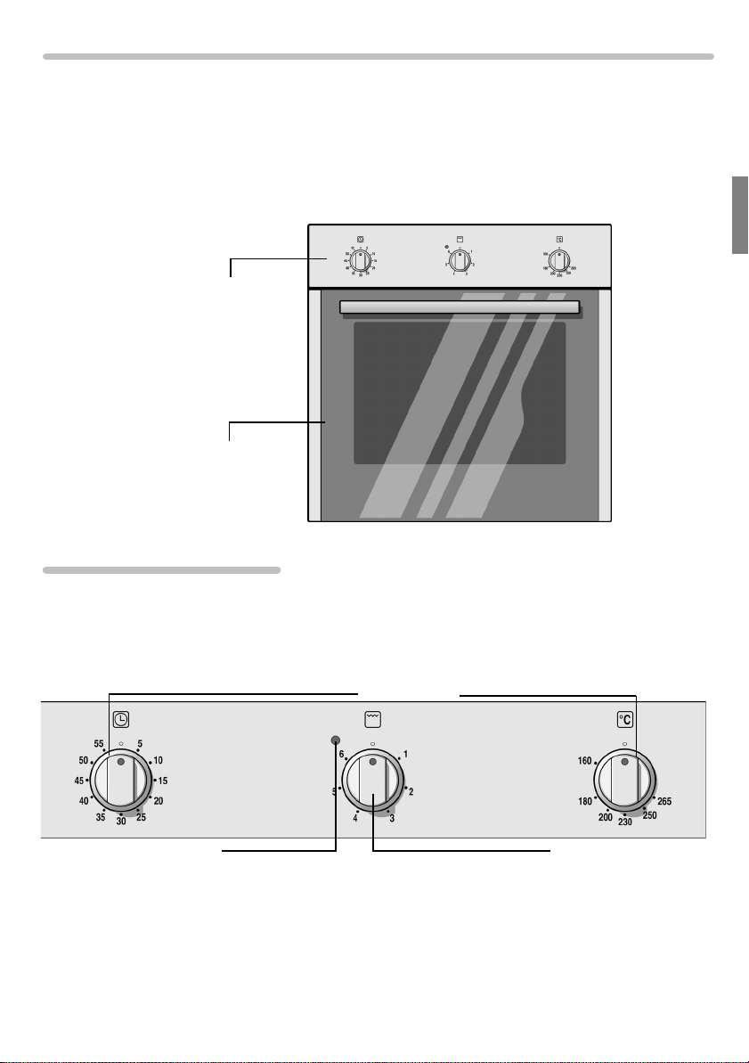
The control panel
Control knob for minute minder
Indicator lamp
Control knob for oven
Control knob for grill
21
The oven
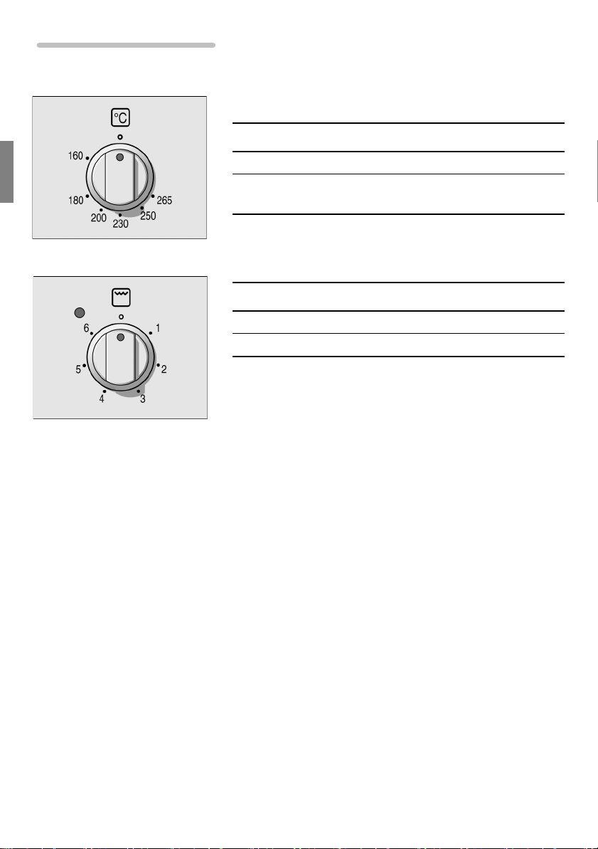
Control knob for oven Use this control knob to set the heat output of the
oven gas burner.
Setting Meaning
=
160-265 Oven gas burner on,
Control knob for grill Use this control knob to set the heat output of the grill.
Setting Meaning
=
Off
1-6
Off
temperature range in °C
Heat output settings of the electric grill
22
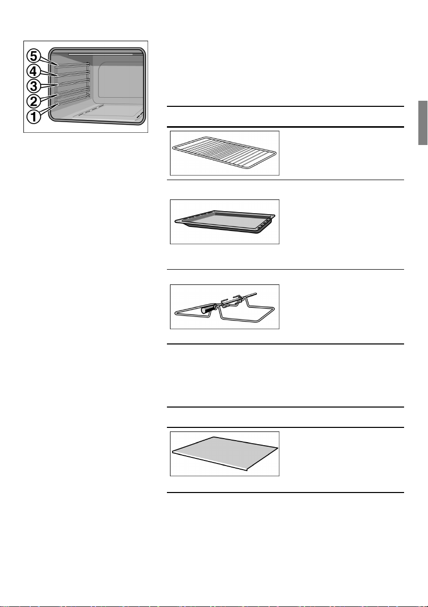
Accessories The accessories can be inserted into the cooking
compartment in five different shelf positions.
You can pull the accessories two-thirds of the way out
without them tipping. This allows meals to be
removed easily.
Accessory Description
Wire rack
For ovenware, cake tins,
roasts,
grilling and frozen
meals.
Enamelled baking tray
For moist cakes, pastries,
frozen meals and large
roasts. Can also be
inserted underneath the
wire rack as a drip tray to
collect run-off fat.
Rotary spit
For roasts and large pieces
of poultry. Use only in
combination with the
enamelled baking tray.
Other accessories
You can buy accessories from the after-sales service
or from specialist retailers.
Accessory Description
Heat shield
For use when operating
the oven gas burner, to
protect food from
excessive heat.
23
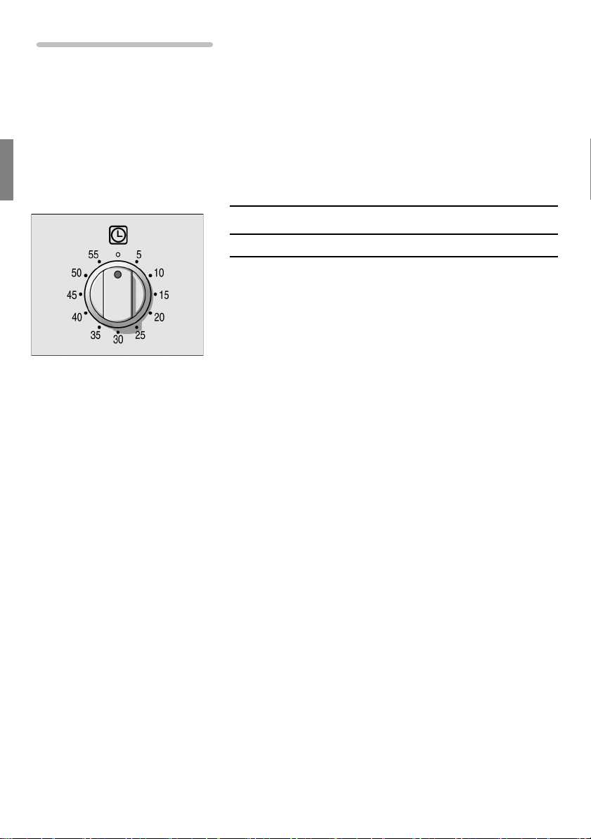
The minute minder
The minute minder is a countdown
timer which emits an audible signal when
the cooking time has elapsed.
The minute minder runs independently of the oven.
Control knob for minute
minder
Use this control knob to set the cooking time.
Setting Meaning
1-59
Cooking time in minutes
24

Before using for the first time
Please read the following instructions before using
your appliance for the first time.
Remove the appliance packaging and dispose of this
appropriately.
Baking out the oven
Cleaning the oven Remove the accessories from the oven.
Remove any leftover packaging, e.g. small pieces of
polystyrene, from inside the oven.
Some parts will be covered with protective film.
Remove this film.
1. Clean the outside of the appliance with a soft,
damp cloth.
2. Clean the interior surfaces of the cooking
compartment with warm soapy water.
Heating up the oven gas
burner
To remove the new cooker smell, heat up the oven
when it is empty and closed.
1. Open the appliance door.
2. Press the control knob for the oven in, turn it anti-
clockwise to
pressed in for a few seconds until the flame has
stabilised. Then close the appliance door.
265 °C
and hold the control knob
3. After 45 minutes, switch the oven off by turning the
control knob clockwise until it reaches =.
Cleaning the oven Once the oven has cooled down, clean the cooking
compartment with warm soapy water.
Cleaning accessories
Before using the accessories, clean them thoroughly
using a cloth and warm soapy water.
25

Operating the oven
Operating modes
Operating mode Use
ð
160-265 °C
Conventional heating
x
1-6
Grill
Operating the oven gas burner
Preparation If you wish to cook something on the baking tray,
For cakes and pastries, bakes, poultry, lean joints of
meat, e.g. beef, veal and game.
For steaks, sausages, fish and toast.
If you wish to heat your oven in the conventional way,
use the oven gas burner.
insert the wire rack on the next shelf position down
and lay the heat shield on it.
If you are cooking something on the wire rack, lay the
heat shield on the wire rack before placing the baking
tin, for example, on top.
Switching on the oven gas
burner
1. Open the appliance door.
2. Press the control knob for the oven in, turn it anti-
clockwise to
pressed in for a few seconds until the flame has
stabilised. Then close the appliance door.
265 °C
and hold the control knob
3. Set the required temperature using the control
knob. Do not turn the knob beyond 160.
Switching off the burner When the dish is ready, press in the control knob
slightly and turn it clockwise to the = position.
The cooling fan may run on, even though the
appliance has already been switched off.
26

If the flame goes out Turn the control knob to the off position. Wait one
minute and switch the burner on again.
If the flame goes out, gas will escape. Do not leave
m
the gas burners unattended while switched on.
Ensure that there are no draughts.
Operating the grill
Never use the oven gas burner and the grill at the
same time.
Switching on the grill Turn the control knob for the grill to the required
setting.
The grill switches on.
Indicator lamp The indicator lamp above the operating knob lights up
when the grill is switched on.
Grill setting Grill temperature Indicator lamp
=
1 - 4 low to medium
5 - 6 medium
When the indicator lamp flashes, the maximum grill
temperature has been reached.
Switching off the grill Turn the control knob for the grill to the = position.
The grill switches off.
The cooling fan may run on, even though the
appliance has already been switched off.
off off
lit
lit
high
flashes
27

Using the rotary spit
You can use the rotary spit to cook large joints such
as rolled joints and poultry to perfection. The meat is
roasted thoroughly and evenly.
Preparing joints Place the joint as centrally as possible on the rotary
spit and secure it at both ends with the retaining clips.
You can also truss the joint with string. With poultry,
bind the ends of the wings underneath the back and
the thighs against the body. This will prevent them
from becoming too dark.
Pierce the skin on the underside of the wings to allow
the fat to escape.
28

Inserting the rotary spit Insert the rotary spit as follows:
1. Place the rotary spit on the frame and slide into
shelf position 2 as far as the limit stop.
2. Slide the rotary spit into the opening in the back
wall of the cooking compartment.
3. Pour a little bit of water into the baking tray and
slide this into shelf position 1 to collect the run-off
fat.
4. Unscrew the handle and close the appliance door.
Switching on the grill Turn the control knob for the grill to the required
setting.
Switching off the grill Turn the control knob for the grill to the = position.
29

Removing the rotary spit
Risk of burns.
m
Never touch the hot surfaces of the cooking
compartment or the heating elements.
Children must always be kept at a safe distance from
the appliance.
Open the appliance door carefully. Hot steam may
escape.
Risk of burns.
m
Never touch the rotary spit or other accessories
directly when they are hot.
Always wear oven gloves or heat-resistant gloves
when handling hot accessories.
Remove the rotary spit as follows:
1. Carefully open the appliance door and screw the
handle back onto the rotary spit.
2. Carefully pull the rotary spit out of the opening in
the back wall of the cooking compartment and
remove the spit.
3. Remove the rotary spit frame and the baking tray.
30

Operating the minute minder
The minute minder runs independently of the oven.
Setting a cooking time Turn the control knob once round clockwise, as far as
the limit stop, and then turn it anti-clockwise to set it
to the required time.
The cooking time has
elapsed
A signal sounds once the time has elapsed.
Cleaning and care
Do not use high-pressure cleaners or steam jets.
m
Risk of short-circuiting.
Never use caustic or abrasive cleaning agents. The
surface could be damaged. If such a substance
comes into contact with the front, wash it off
immediately with water.
Do not clean any surfaces of the appliance while they
are hot.
Catalytic side panels
Self-cleaning surfaces Catalytic side panels are coated with self-cleaning
enamel. The surfaces clean themselves while the
oven is in operation. Larger splashes will only be
removed after the oven has been used several times.
Never clean these surfaces with oven cleaner.
Slight discolouration of the enamel does not affect
automatic self-cleaning.
31

Using the correct cleaning agent
Do not use cleaning agents which contain abrasive
substances or acid, or cleaning aids such as steel
wool or scouring pads. These may damage the
surfaces.
Appliance component Cleaning agent and aid
Appliance door seal
Appliance door panel
Control panel and control
knobs
Cooking compartment
interior
Enamelled surfaces
Gas burners
Appliance exterior
Stainless steel surfaces
Door handle
Accessories
• Use warm soapy water.
• Use glass cleaner.
• Do not use a glass scraper.
• Wipe with a soft, damp cloth.
• Use warm soapy water or a vinegar solution; dry with
a soft cloth.
• For stubborn dirt or very heavy build-up, use
commercially available oven cleaner; rinse
thoroughly with clean water.
• Never clean the gas burners in the oven yourself.
• Use warm soapy water; dry with a soft cloth.
• Always remove any flecks of limescale, grease,
starch and egg white immediately.
• Special stainless steel cleaning agents can be
obtained from the after-sales service or from
specialist retailers.
• Wipe with a soft, damp cloth.
• Soak in hot soapy water; clean with a brush or
sponge.
32

Removing and fitting the appliance door
You can remove the appliance door for easier
cleaning.
The hinges of the appliance door are each secured
by a locking lever.
When the locking lever is folded in (A), the appliance
door is secured. It cannot be unhinged.
If the locking lever is open (B), only the hinge is
secured, and you can remove the appliance door.
Risk of injury.
Do not reach inside the hinge.
Removing the appliance
door
Proceed as follows:
1. Open the appliance door.
2. Lift up the locking levers on both sides.
3. Close the appliance door until you feel resistance
at an angle of around 15° (in relation to the closed
appliance door).
4. Grip the door on either side with both hands.
5. Close the appliance door a little further.
6. Lift the door upwards and at an angle to remove it.
Do not disassemble the door.
33

Fitting the appliance door Proceed as follows:
1. Hold the appliance door at an angle.
2. Insert both hinges, left and right, into the supports.
3. Position the door so that the hinge grooves
engage on both sides.
4. Open the appliance door.
5. Fold in the locking levers on both sides.
6. Close the appliance door.
34

Removing and inserting the hook-in racks
You can remove the hook-in racks in order to clean
them separately.
The hook-in racks are fixed to the walls of the cooking
compartment at three points.
Removing the hook-in
racks
To remove the hook-in racks, proceed as follows:
1. Hold the middle of the hook-in rack and push it
upwards.
The front hook of the rack will release.
2. Hold the front of the hook-in rack and fold it back.
At the same time, keep hold of the catalytic side
panel, then pull the hook-in rack out of the holes.
35

Inserting the hook-in rack To reinsert the hook-in racks, proceed as follows:
1. Insert the rear hooks through the rear holes in the
catalytic side panel into the holes in the side wall
of the cooking compartment.
2. Press the catalytic side panel onto the cooking
compartment, hold it in place and fold the hook-in
rack forwards then hook it into the front hole.
36

Faults and after-sales service
Malfunctions often have simple explanations.
Please read the following notes before calling the
after-sales service.
Instructions for remedial
Problem Possible cause
action
The door panel steams up when
the oven is hot.
The flame (oven) does not burn
through all outlet openings.
The appliance does not work. Faulty fuse Look in the fuse box and
The oven light does not work. Oven light is faulty Replace the oven light.
Normal occurrence;
caused by the
difference in
temperature.
Normal build-up of dirt The burner must be
Power failure Check whether the kitchen
Repairs may only be carried out by fully trained aftersales service engineers.
Incorrect repairs may result in significant risk to the
user.
Not possible; this has no
effect on oven performance.
professionally cleaned.
check that the fuse for the
appliance is in working
order.
light, for example, is
working.
(see "Replacing oven light"
section)
37

After-sales service
Our after-sales service is here to help if your
appliance ever needs to be repaired. You can find the
address and telephone number of your nearest aftersales service point in the enclosed after-sales service
directory or in the telephone directory. The after-sales
service centres listed will also be happy to advise you
of a service point in your local area.
E number and FD number Please quote the E number (product number) and the
FD number (production number) of your appliance
when contacting the after-sales service. You will find
these numbers on the rating plate, which you can see
in the middle of the inside edge of the main oven
when the oven door is open. You can make a note of
these numbers in the space below to save time in the
event of your appliance malfunctioning.
E no.
After-sales service
FD no.
38

Replacing the oven light
If the oven light bulb fails, it must be replaced.
Replacement heat-resistant bulbs can be obtained
from the after-sales service or from specialist
retailers. Please specify the E number and
FD number of your appliance. Do not use any other
type of bulb.
Proceed as follows:
1. Switch off the relevant circuit breaker in the fuse
2. Open the oven door.
3. Place a tea towel in the cold oven to prevent
4. Remove the glass cover from the bulb inside the
5. Replace the bulb with one of the same type.
box.
damage.
cooking compartment by turning it anti-clockwise.
Voltage: 230 V / 50 Hz
Power: 15 W
Screw thread: E14
Heat resistance: 300°C
6. Screw on the glass cover again.
7. Remove the tea towel and switch the circuit
breaker back on.
39

Tips and tricks
The following are tips and tricks to help you when
cooking food in your appliance.
Tips for saving energy
Heat shield Always use the heat shield when you use dark-
coloured baking tins and trays; otherwise, they will
absorb too much heat from the burners.
Several cakes It is best to bake several cakes one after the other.
The oven is still warm. This reduces the baking time
for the second cake. You can also place two cake tins
next to each other.
Use the residual heat When cooking foods with longer cooking times, you
can switch the oven off 5 minutes before the end of
the cooking time and use the residual heat to finish
the cooking.
Close the oven door Always keep the appliance door closed when the gas
burners are switched on. If you need to open the
appliance door, close it again as soon as possible.
Otherwise, the temperature will drop and the oven will
need to heat itself up again.
Tips for using your appliance
The following tips relate to ovenware and cooking
and explain what to do if something goes wrong.
General tips since a lower temperature allows more even
browning.
Clean the oven and accessories after each use, once
they have cooled down.
Always place baking tins or ovenware in the centre of
the wire rack.
40

Baking
Baking tins Use light-coloured baking tins and trays wherever
possible.
Baking tips The table below contains additional information on
how to be successful at baking.
How to confirm whether your
sponge cake is cooked
through.
The cake collapses.
The cake has risen high in the
middle and less around the
edges.
The cake is too dark on the
top.
The cake is too dry.
The bread or cake looks good
but it is streaked with water
inside.
The pastries are not evenly
browned.
Around 10 minutes before the end of the baking time
stated in the recipe, pierce the highest point of the
cake with a wooden skewer. If no cake mixture sticks
to the wood, the cake is ready.
Next time, use less liquid or bake at a slightly lower
temperature. Note the stirring times indicated in the
recipe.
Do not grease the edges of the baking tin. After
baking, carefully loosen the cake using a knife.
Place the cake lower in the oven and bake at a lower
temperature for slightly longer.
Make tiny holes in the finished cake using a cocktail
stick. Then pour fruit juice or an alcoholic drink over
the cake. Next time, bake at a slightly higher
temperature for less time.
Next time, use less liquid and bake at a lower
temperature for slightly longer. For cakes with a moist
topping: Pre-bake the base first. Sprinkle the base
with almonds and breadcrumbs and then pour the
topping on. Take care to follow recipes and baking
times.
Set the temperature slightly lower. Excess
greaseproof paper can affect the air circulation.
Always cut the greaseproof paper down to the size of
the baking tray.
41

Roasting
Ovenware You can use ovenware made from enamel, fireproof
glass, clay or cast iron. The enamelled baking tray is
also suitable for large roasts.
Roasting tips Depending on the size of the joint, add 2 or
3 tablespoons of liquid to lean meat and 8 to
10 tablespoons of liquid to pot roasts.
When cooking duck or goose, pierce the skin on the
underside of the wings to allow the fat to escape.
Poultry will turn out particularly crispy and brown if
you baste it towards the end of the roasting time with
butter, salted water or orange juice.
Turn pieces of meat halfway through the roasting
time.
When roasting large pieces of meat, you may find
that the amount of steam and condensation on the
oven door is more than usual. This is a normal
occurrence which has no effect on the oven's
performance. Once roasting is complete, dry the
oven door and window with a cloth.
42
If you are roasting on the wire rack, insert the
enamelled baking tray into shelf position 1 to collect
the run-off fat.

The table below contains additional information on
how to be successful at roasting.
How can you tell when the
roast is ready?
The roast is too dark and the
crackling is burnt in places.
The roast looks good but the
juices are burnt.
The roast looks good, but the
juices are too clear and
watery.
Use a meat thermometer (available from specialist
retailers) or carry out a "spoon test".
press down on the roast with a spoon. If it feels firm, it
is ready. If the spoon can be pressed in, it needs to be
cooked for a little longer.
Check the shelf position and temperature.
Next time, use a smaller roasting dish and add more
liquid.
Next time, use a larger roasting dish and add less
liquid.
Grilling
Grilling tips Drizzle some oil over the food to be grilled before you
place it on the wire rack under the grill.
Please note that the grilling surface is smaller than
the wire rack.
Place the food to be grilled in the centre of the wire
rack. Pour a little bit of water into the enamelled
baking tray and insert this into the shelf position
underneath the grill to collect the run-off fat. Never
place it on the cooking compartment floor.
If possible, grill items should be of equal thickness.
They should be at least 2 to 3 cm thick. This ensures
that they brown evenly while also remaining
succulent.
If the food to be grilled is thin, turn it over halfway
through grilling; if it is thick, turn it over several times
during grilling. Use tongs when turning the food to
avoid piercing it and, in the case of meat, to keep the
meat juices inside the meat.
Dark meats such as lamb and beef brown better and
more quickly than light meats such as pork and veal.
43

Notice de montage et d'installation 44-58 | Notice d'utilisation 59-88
Notice de montage et d'installation
Consignes de sécurité _______________________________________ 45
Avant l'encastrement ________________________________________46
Appareil ........................................................................................................ 46
Directives en matière de ventilation et d'aération......................................... 48
Raccordement électrique _____________________________________ 49
Raccordement au gaz ________________________________________ 51
Encastrement et dépose de l'appareil___________________________ 55
Adaptation de l'appareil au type de gaz _________________________56
Brûleur du four.............................................................................................. 56
Tableau général des injecteurs .................................................................... 58
44

Consignes de sécurité
Seuls un montage et une installation appropriés
respectant la présente notice garantissent la sécurité
d'utilisation. L'installateur est seul responsable en
cas de dommages ou de dysfonctionnements dus à
un montage ou une installation non conforme.
Tous les travaux d'installation et de réglage ainsi que
le changement à un autre type de gaz doivent être
effectués par un spécialiste agréé et en respectant
les réglementations et prescriptions des fournisseurs
de gaz locaux.
Coupez l'arrivée de gaz avant tous travaux.
Vérifiez la compatibilité de votre installation (type de
gaz et pression de gaz) avec le réglage de l'appareil
avant de l'installer. Les conditions de réglage de
l'appareil figurent sur la plaque signalétique.
45

Avant l'encastrement
Respectez les indications suivantes pour l'appareil
ainsi que les directives en matière d'aération et de
ventilation.
Appareil
Dimensions de l'appareil Respectez les dimensions indiquées.
Situations d'encastrement Cet appareil peut être encastré de façon suivante :
• Sous un plan de travail
• Au-dessus d'un autre appareil
46

Meubles adjacents Les meubles adjacents ne doivent pas être en
matériaux inflammables. Les façades des meubles
adjacents doivent pouvoir résister à une température
d'au moins 120 °C.
Vernissez les faces coupées avec une colle spéciale
résistante à l'eau.
Si l'appareil est installé à une distance rapprochée
des autres unités, vous devez tenir compte des
distances minimales indiquées :
47

Plaque signalétique Les caractéristiques techniques de l'appareil figurent
sur la plaque signalétique. Elle est située à l'arrière
de l'appareil et, la porte ouverte, sur le côté gauche
du compartiment de cuisson. Ne retirez jamais la
plaque signalétique de l'appareil.
Les valeurs de réglage sont indiquées sur la plaque
signalétique à droite à l'arrière de l'appareil.
Indiquez dans le tableau ci-dessous
le numéro de produit (E),
le numéro de fabrication (FD),
le réglage usine pour le type de gaz et la pression de
gaz ainsi que la nouvelle valeur pour le type de gaz
et la pression de gaz si ces valeurs ont été modifiées.
N° E N° FD
Service après-vente
Type de gaz
Pression de gaz
(réglage usine)
Type de gaz
Pression de gaz
(adaptation)
Directives en matière de ventilation et d'aération
Cet appareil ne doit être installé que dans une pièce
suffisamment ventilée et conformément aux
réglementations et directives en vigueur en matière
de ventilation.
Cet appareil n'est pas raccordé à un système
d'extraction de fumée. Installez l'appareil en veillant à
assurer une ventilation naturelle ou contrôlée par
l'intermédiaire des ouvertures de ventilation ou des
conduits adéquats. La ventilation doit permettre la
combustion continue et suffisante de la quantité d'air
nécessaire ainsi que l'évacuation de l'air consommé.
48

Raccordement électrique
Seul un spécialiste agréé est habilité à raccorder
l'appareil.
L'appareil doit être installé conformément aux
dernières directives IEE (Institution of Electrical
Engineers). L'appareil risque d'être endommagé en
cas de raccordement incorrect.
Assurez-vous que la tension d'alimentation concorde
avec la valeur indiquée sur la plaque signalétique. La
plaque signalétique se trouve au dos de l'appareil.
Assurez-vous que le réseau électrique est
correctement mis à la terre et que le système de
câbles et de conduites dans le bâtiment supporte la
charge de l'appareil.
En cas de raccordement direct au réseau électrique,
il est nécessaire de prévoir un dispositif de coupure
omnipolaire avec un écartement des contacts de 3
mm.
La séparation totale dans des conditions prévues
dans la catégorie de surtension III doit être garantie.
Le câble de mise à la terre en est excepté.
Installez le câble secteur de telle façon qu'il ne sera
pas coincé ou écrasé. Le câble ne doit pas entrer en
contact avec des arêtes de coupe ou des arêtes
vives.
49

Raccordement du câble
secteur
Le raccordement du câble secteur a lieu au moyen de
la barrette à bornes. Le câble secteur doit être du
type suivant :
• H05RRF ou H05RNF
• 3 x 1,5 mm²
• 220-240 V~
Voici comment procéder :
• Ouvrez le boîtier de connexions à l'arrière de
l'appareil.
• Sur la barrette à bornes, desserrez la vis qui fixe
le câble.
• Desserrez les contacts de vis. Le câble doit
correspondre aux données prescrites et être
suffisamment long.
• Relier le fil jaune-vert à la borne $. Ce fil doit être
d'au moins 30 mm plus long que les autres fils.
• Reliez le conducteur neutre bleu à la borne N.
• Reliez le câble d'alimentation à la borne L.
50

Raccordement au gaz
Le raccordement au gaz de l'appareil doit être
conforme aux réglementations actuelles en vigueur.
Vérifiez la compatibilité de votre installation (type de
gaz et pression de gaz) avec le réglage de l'appareil
avant de l'installer. Les conditions de réglage de
l'appareil figurent sur la plaque signalétique.
Le raccordement des conduites de gaz ainsi que les
joints doivent être réalisés par un spécialiste agréé
conformément aux normes actuelles en vigueur.
Raccord de gaz de
l'appareil
Le raccord de gaz (ISO 228-1) se situe à gauche à
l'arrière de l'appareil.
L'appareil est livré avec les raccords suivants :
Raccord Description
Coude ISO 228-1/ISO 228-1
(et joint)
Coude ISO 228-1/ISO 7-1
(et joint)
Embout pour tubes ondulés
ISO 228-1/LPG (et joint)
51

Raccord selon le pays
ISO 228-1 + embout
pour tubes ondulés
AE X X
AF X X
BD X X
BH X X
DZ X X
EG X X
GH X X
IR X X
JO X X
KW X X
LB X X
LY X X
MA X X
OM X X
PK X X
QA X X
SA X X
SD X X
SY X X
TN X X
YE X X
ISO 7-1
52

Raccordement au gaz
naturel
A
B
C
D
Pour le raccordement, procédez de façon suivante :
• Vissez la pièce de raccordement (C) et le joint (B)
avec le raccord de gaz (A).
• Tenez avec une clé le coude de raccordement
ISO228-1/
raccordement à une conduite de raccordement
rigide ou à un flexible de gaz (D).
Utilisez exclusivement des conduites de raccordement ou des flexibles qui répondent aux prescriptions en vigueur et qui sont agréés pour cet
usage.
Pour étancher le filetage, utilisez exclusivement
des matériaux d'étanchéité agréés.
ISO 7-1
(C) et vissez la pièce de
Raccordement au gaz
liquide
A
B
C
D
E
F
G
Pour le raccordement, procédez de façon suivante :
• Vissez le coude de raccordement
ISO228-1/
raccord de gaz (A).
• Vissez l'embout pour tubes ondulés (E) et le joint
(D) avec le coude de raccordement (C+A).
• Tenez avec une clé l'embout pour tubes
ondulés (E) et vissez la pièce de raccordement
sur un flexible de gaz (G).
• Serrez le collier (F).
Utilisez exclusivement des conduites de raccordement ou des flexibles qui répondent aux prescriptions en vigueur et qui sont agréés pour cet
usage.
Pour étancher le filetage, utilisez exclusivement
des matériaux d'étanchéité agréés.
ISO228-1
(C) et le joint (B) avec le
53

Flexibles Si vous utilisez des flexibles, assurez-vous que ceux-
ci :
• ne sont ni coincés ni écrasés.
• ne sont pas soumis à des forces de traction ou de
torsion.
• ne sont pas en contact avec des bords coupants,
arêtes vives.
• ne sont pas en contact avec des éléments
chauds, comme le dessous, l'arrière et le dessus
du four.
Assurez-vous que toute la longueur des flexibles sera
accessible pour une vérification.
Vanne de sécurité L'installation d'une vanne de sécurité pour l'ouverture
et la fermeture de l'arrivée de gaz est obligatoire.
Installez la vanne de sécurité entre la conduite
d'arrivée de gaz vers le local correspondant et
l'appareil. Veillez à ce qu'il soit possible d'accéder à
tout instant à cette vanne.
Contrôle de l'étanchéité Contrôlez l'étanchéité des raccordements avec une
solution savonneuse après avoir raccordé la conduite
de gaz.
Mise en service Mettez l'appareil en service en procédant selon la
notice d'utilisation.
Allumez tous les brûleurs et vérifiez la stabilité des
flammes lors d'un réglage à une grande et à un faible
hauteur.
54

Encastrement et dépose de l'appareil
Encastrement de l'appareil Pour l'encastrement de l'appareil, procédez de façon
suivante :
• Pousser l'appareil jusqu'au fond et le centrer.
Veillez à ne pas plier ou coincer les conduites et
câbles de raccordement et à ne pas les passer
par-dessus d'arêtes vives.
• Aligner l'appareil à l'horizontale, en tenant
compte de la fente d'aération indiquée de 15 mm
au-dessus de l'appareil.
• Visser l'appareil avec l'armoire au moyen des
4 vis de fixation.
Dépose de l'appareil Pour la dépose de l'appareil, procédez de façon
suivante :
• Mettre l'appareil hors tension. Couper l'arrivée de
gaz.
• Dévisser les vis de fixation, lever légèrement
l'appareil et le retirer complètement.
• Si nécessaire, détacher le raccord électrique et
de gaz conformément aux prescriptions.
55

Adaptation de l'appareil au type de gaz
Si l'appareil n'est pas déjà réglé pour le type de gaz à
disposition, il est nécessaire de l'adapter.
Cette adaptation doit être effectuée par un spécialiste
agréé, conformément aux réglementations en
vigueur.
Le type et la pression de gaz qui ont été réglés en
usine sont indiqués sur la plaque signalétique.
Pour changer le type de gaz, il est nécessaire de
changer les injecteurs et de régler la petite flamme.
Brûleur du four
Changement de l'injecteur Voici comment procéder :
• Démontez le fond d'insertion du four.
• Dévissez la vis à l'avant du brûleur de four et
tirez-le légèrement vers le haut.
• Dévissez l'injecteur et remplacez-le par un
injecteur approprié au nouveau type de gaz (voir
le paragraphe “Tableau général des injecteurs”).
• Pour le montage, procédez dans l'ordre inverse.
56

Réglage de la petite flamme Voici comment procéder :
• Ouvrez la porte de l'appareil. Appuyez sur la
manette de commande et tournez-la à gauche
sur la position maximale
Le brûleur s'allume, maintenez la manette
appuyée pendant environ 15 secondes et
relâchez-la.
• Fermez la porte de l'appareil. Retirez la manette
de commande.
• Desserrez légèrement la vis de réglage intérieure
en passant par l'orifice du robinet de gaz du
bandeau de commande.
• Remettez la manette en place et chauffez le four
pendant 15 min.
• Tournez ensuite la manette de commande sur la
position minimale 160
• Retirez à nouveau la manette de commande.
• En passant par l'orifice du robinet de gaz du
bandeau de commande, réglez ensuite la vis de
réglage intérieure jusqu'à ce que la flamme soit
correctement stable.
Desserrez la vis de réglage pour augmenter le
débit de gaz ou serrez-la pour le réduire. Le
réglage est optimal lorsque la petite flamme
atteint une taille d'environ 3 à 4 mm.
Lors du raccordement de gaz liquide, serrer la vis
de réglage.
• Remettez la manette en place.
• Assurez-vous que la flamme ne s'éteint pas lors
d'une commutation rapide entre le débit de gaz
minimal et maximal et inversement et lors de
l'ouverture et de la fermeture de la porte de
l'appareil.
265
.
.
57

Tableau général des injecteurs
Type de gaz
Gaz naturel
G20 (E)
Gaz liquide
Butane
Propane
G30/G31
mbar
20 115 Ecarte-
28-30/
37
N° d'injecteur
Injec-
teur Bypass
ment
75 0,48
Type de brûleur Puissance
(W)
Brûleur du four
Brûleur du four
2400 229 l/h
2400 175 g/h
Consom-
mation
max.
58

Notice d'utilisation
Remarques importantes ______________________________________ 60
m Consignes de sécurité.............................................................................. 61
Dommages matériels ................................................................................... 63
Votre nouvel appareil ________________________________________64
Bandeau de commande ............................................................................... 64
Le four .......................................................................................................... 65
La minuterie.................................................................................................. 67
Avant la première utilisation __________________________________ 68
Chauffe à vide du four .................................................................................. 68
Nettoyage des accessoires .......................................................................... 68
Utilisation du four ___________________________________________ 69
Utilisation du brûleur de four ........................................................................ 69
Utilisation du gril ........................................................................................... 70
Utilisation du tournebroche........................................................................... 71
Utilisation de la minuterie_____________________________________ 74
Nettoyage et entretien________________________________________74
Parois latérales catalytiques......................................................................... 74
Utiliser les produits de nettoyage appropriés ............................................... 75
Décrocher et accrocher la porte de l'appareil............................................... 76
Retrait et montage des grilles....................................................................... 78
Pannes et service après-vente_________________________________ 80
Service après-vente ..................................................................................... 81
Remplacement de la lampe du four ............................................................. 82
Conseils et astuces__________________________________________ 83
Conseils pour économiser de l'énergie ........................................................ 83
Conseils pour l'utilisation.............................................................................. 83
Cuisson des pâtisseries ..................................................................... 84
Cuisson .............................................................................................. 85
Grillades ............................................................................................. 86
59

Remarques importantes
Prenez le temps de lire attentivement la présente
notice d'utilisation.
C'est la seule façon d'utiliser correctement et en toute
sécurité votre nouvel appareil.
Conservez avec soin les notices d'utilisation et de
montage ainsi que les différents accessoires. Si vous
vous débarrassez de l'appareil au profit d'une tierce
personne, n'oubliez pas de lui fournir les notices et
les accessoires.
Avaries de transport Contrôlez l'état de l'appareil après l'avoir déballé. Si
vous constatez des avaries de transport, vous ne
devez pas brancher l'appareil.
Mise au rebut respectueuse
de l'environnement
Raccordement au gaz Faites appel à un spécialiste agréé pour le
Eliminez l'emballage de manière écologique.
Cet appareil est commercialisé en accord avec la
directive européenne 2002/96/CE sur les déchets
¦
des équipements électriques et électroniques
(directive DEEE).
raccordement au gaz ainsi que pour le changement à
un autre type de gaz.
L'appareil est livré avec une notice de montage.
Tout droit à la garantie sera annulé en cas de
raccordement incorrect de l'appareil. Nous déclinons
toute responsabilité pour des dommages et pannes
résultant d'un raccordement ou d'un réglage
incorrect.
60

m Consignes de sécurité
Cet appareil est exclusivement destiné à un usage
domestique.
Il ne doit être utilisé que pour les préparations
culinaires.
Ne laissez jamais des adultes ou des enfants s'en
servir sans les surveiller
• si ceux-ci ne sont pas physiquement ou
mentalement en mesure de l'utiliser en toute
sécurité
• ou s'ils ne disposent pas d'une connaissance et
d'une expérience suffisante en la matière.
Ne jamais laisser des enfants jouer avec l'appareil.
Surfaces chaudes Risque de brûlures !
Ne jamais toucher les surfaces chaudes du
compartiment de cuisson ni les résistances
chauffantes.
Eloignez systématiquement les enfants.
Ouvrir prudemment la porte de l'appareil. De la
vapeur chaude peut s'échapper.
Risque d'incendie !
Ne jamais conserver des objets inflammables dans le
four.
Risque de court-circuit !
Ne jamais coincer le câble de raccordement d'un
appareil électrique dans la porte du four chaude.
L'isolation du câble peut fondre.
Alcool fort Attention en cas de mets qui sont préparés avec des
boissons fortement alcoolisées (p.ex. Cognac,
Rhum).
L'alcool s'évapore à des températures élevées. Dans
des conditions défavorables, les vapeurs d'alcool
risquent de s'enflammer dans l'appareil.
Risque de brûlures !
Utilisez uniquement des petites quantités de
boissons fortement alcoolisées et ouvrez
prudemment la porte de l'appareil.
61

Aération insuffisante lors
de l'utilisation des brûleurs
Réparations Risque de choc électrique !
N'utilisez jamais les brûleurs dans des pièces non
aérées. Les brûleurs dégagent en plus de la chaleur
et de l'humidité.
Les réparations inexpertes sont dangereuses.
Seul un technicien du service après-vente formé par
nos soins est habilité à effectuer les réparations.
Si l'appareil est défectueux, fermer l'arrivée du gaz.
Appelez le service après-vente.
Anomalies au niveau de
l'installation de gaz / odeur
de gaz
Vanne de sécurité Fermez la vanne de sécurité à la conduite d'arrivée
Voici ce que vous devez impérativement faire si vous
constatez une odeur de gaz ou des anomalies au
niveau de l'installation de gaz :
• fermez immédiatement l'arrivée du gaz ou le
robinet de la bouteille de gaz
• éteignez immédiatement tout feu nu et cigarettes
• éteignez les appareils électriques, même les
lampes
• ouvrez les fenêtres et aérez en grand la pièce
• appelez le service après-vente ou la société de
distribution de gaz.
du gaz si l'utilisation de l'appareil est longtemps
interrompue.
62

Dommages matériels
Dommages au niveau du
four
Dommages au niveau des
façades des meubles
voisins
Ne disposez jamais de plats directement sur la sole
du four. N'enfournez pas de plaque à pâtisserie sur la
sole du four. Ne recouvrez pas la sole du four de
papier d'aluminium.
Ne placez pas de vaisselle sur la sole du four. Cela
crée une accumulation de chaleur. Le temps de
cuisson n'est plus le même et l'émail sera
endommagé.
Ne versez jamais d'eau dans le four chaud. Cela
endommage l'émail.
Si vous voulez cuire des gâteaux aux fruits très
juteux, ne garnissez pas trop la plaque. Le jus de
fruits qui goutte de la plaque laisse des taches
définitives.
Ne montez pas sur la porte du four ouverte et ne vous
asseyez pas dessus.
Ne laissez refroidir le four qu'avec la porte fermée.
Même si vous n'entrouvrez que légèrement la porte
du four, les façades des meubles voisins peuvent
être endommagées au bout d'un moment.
Si le joint du four est fortement encrassé, la porte de
l'appareil ne ferme plus correctement lors du
fonctionnement. Les façades des meubles voisins
seront endommagées avec le temps. Le joint doit
toujours être propre.
63

Votre nouvel appareil
Les informations qui suivent vont vous permettre de
vous familiariser avec votre nouvel appareil. Vous
obtiendrez des informations sur le bandeau de
commande et le four ainsi que sur les modes de
fonctionnement et les accessoires joints.
Bandeau de
commande
Four
Bandeau de commande
Manette de commande
Fonctions supplémentaires du four
Voyant lumineux
64
Manette de commande
Manette de commande Minuteur
Four

Le four
Manette de commande
Four
Manette de commande Gril Cette manette de commande sert à régler la
Cette manette de commande sert à régler la
puissance de chauffe du brûleur du four.
Position Signification
=
160-265 Brûleur du four allumé, fourchette de
puissance de chauffe du gril.
Position Signification
=
Eteint
1-6 Puissances de chauffe du gril électrique
Eteint
température en °C
65

Accessoires Les accessoires peuvent être enfournés à cinq
niveaux différents.
Vous pouvez sortir l'accessoire aux deux tiers sans
qu'il ne bascule. Il est ainsi plus facile de retirer les
plats du four.
Accessoire Description
Grille
Pour plats, moules à
gâteau, rôtis,
grillades et
plats surgelés.
Plaque à pâtisserie
émaillée
Pour gâteaux fondants,
pâtisseries, plats surgelés
et gros rôtis. Enfournée
sous la grille elle peut
aussi être utilisée comme
collecteur de graisse.
Tournebroche
Pour des rôtis et des
grosses volailles. L'utiliser
uniquement en
combinaison avec la
plaque à pâtisserie
émaillée.
Autres accessoires
66
Vous pouvez racheter des accessoires auprès de
notre service après-vente ou d'un revendeur
spécialisé.
Accessoire Description
Plaque anti-chaleur
Pour le fonctionnement du
brûleur du four, afin de
protéger les mets contre
une trop forte chaleur.

La minuterie
La minuterie est un réveil comptant à rebours qui
émet un signal sonore après écoulement de la durée
réglée.
Elle fonctionne indépendamment du four.
Manette de commande de
la minuterie
Cette manette de commande permet de régler la
durée.
Position Signification
1-59
Durée en minutes
67

Avant la première utilisation
Lisez attentivement les consignes qui suivent avant
d'utiliser votre appareil pour la première fois.
Retirez l'emballage de l'appareil et éliminez-le
conformément aux réglementations en la matière.
Chauffe à vide du four
Pré-nettoyage du four Retirez les accessoires du four.
Enlevez tous les résidus de l'emballage, p.ex. des
pièces de polystyrène, du four.
Certaines parties sont recouvertes d'un film
protecteur. Retirez-le.
1. Nettoyez l'extérieur de l'appareil avec un chiffon
doux humide.
2. Nettoyez les surfaces intérieures du compartiment
de cuisson avec de l'eau tiède additionnée de
produit à vaisselle.
Chauffer le brûleur du four Pour éliminer l'odeur du neuf, laissez chauffer le four
à vide, porte fermée.
1. Ouvrez la porte de l'appareil.
2. Appuyez sur la manette de commande du four,
tournez-la à gauche sur
manette de commande appuyée pendant
quelques secondes jusqu'à ce que la flamme soit
stable. Fermez ensuite la porte de l'appareil.
3. Eteignez le four au bout de 45 minutes en tournant
la manette de commande à droite sur la position =.
265 °C
et maintenez la
Post-nettoyage du four Après son refroidissement, nettoyez le compartiment
de cuisson avec de l'eau tiède additionnée de produit
à vaisselle.
Nettoyage des accessoires
Avant d'utiliser les accessoires, nettoyez-les
soigneusement avec de l'eau additionnée de produit
à vaisselle et une lavette.
68

Utilisation du four
Modes de fonctionnement
Mode de fonctionnement Usage
ð
160-265 °C
Chauffage conventionnelle
x
1-6
Gril
Utilisation du brûleur de four
Préparation Si vous désirez préparer un mets sur la plaque à
Pour des gâteaux et pâtisseries, soufflés, volailles,
pièces de rôtis maigres de boeuf, veau et gibier.
Pour des steaks, saucisses, poissons et toasts
Si vous désirez chauffer votre four
conventionnellement, utilisez le brûleur du four.
pâtisserie, enfournez la grille à un niveau inférieur et
placez dessus la plaque anti-chaleur.
Si vous préparez un mets sur la grille, placez la
plaque anti-chaleur sur la grille avant de placer p.ex.
le moule dessus.
Allumer le brûleur du four
Eteindre le brûleur
1. Ouvrez la porte de l'appareil.
2. Appuyez sur la manette de commande du four,
tournez-la à gauche sur
manette de commande appuyée pendant
quelques secondes jusqu'à ce que la flamme soit
stable. Fermez ensuite la porte de l'appareil.
265 °C
et maintenez la
3. Avec la manette de commande, réglez la
température désirée. Ne tournez pas plus loin que
la position 160.
Lorsque le mets est prêt, tournez la manette de commande vers la droite sur la position =, tout en appuyant légèrement sur la manette.
Le ventilateur de refroidissement peut continuer à
fonctionner bien que l'appareil soit déjà éteint.
69

Si le flamme s'éteint à
nouveau
Placez la manette de commande sur la position Arrêt.
Attendez une minute et répétez l'allumage.
Du gaz s'échappe lorsque la flamme s'éteint. Ne
m
laissez pas les brûleurs à gaz sans surveillance
pendant qu'ils fonctionnent. Assurez-vous qu'il n'y a
pas de courant d'air.
Utilisation du gril
N'utilisez jamais le brûleur du four et le gril
simultanément.
Allumer le gril Tournez la manette de commande du gril sur la
position gril désirée.
Le gril s'allume.
Voyant lumineux Le voyant lumineux au-dessus de la manette de
commande est allumé lorsque le gril est en marche.
Voyant
Position gril Température du gril
lumineux
=
1 - 4 faible à moyen
5 - 6 moyen
Lorsque le voyant lumineux clignote, la température
maximum du gril est atteinte.
Eteindre le gril Tournez la manette de commande du gril sur la
position =.
Le gril s'éteint.
Le ventilateur de refroidissement peut continuer à
fonctionner bien que l'appareil soit déjà éteint.
Eteint Eteint
Allumé
Allumé
puissant
Clignote
70

Utilisation du tournebroche
Le tournebroche est idéal pour préparer de gros rôtis,
comme du rôti roulé et de la volaille. La viande sera
cuite uniformément.
Préparer le rôti Embrochez le rôti sur le tournebroche en le centrant
autant que possible et fixez-le aux deux extrémités
avec les crochets.
De plus, vous pouvez fixer le rôti avec du fil de
cuisine. En cas de volaille, fixez les extrémités des
ailes sous le dos et les cuisses au corps. De cette
sorte, elles ne brunissent pas trop.
Piquez la peau sous les ailes afin que la graisse
puisse s'écouler.
71

Mise en place du
tournebroche
Pour la mise en place du tournebroche, procédez de
façon suivante :
1. Poser le tournebroche sur le support et l'introduire
à la hauteur d'enfournement 2 jusqu'en butée.
2. Introduire le tournebroche dans l'orifice situé dans
la paroi arrière du compartiment de cuisson.
3. Verser un peu d'eau sur la plaque à pâtisserie et
l'enfourner au niveau 1 comme collecteur de
graisse.
4. Dévisser la poignée et fermer la porte de l'appareil.
Allumer le gril Tournez la manette de commande du gril sur la
position gril désirée.
Eteindre le gril Tournez la manette de commande du gril sur la
position =.
72

Retirer le tournebroche
Risque de brûlures !
m
Ne jamais toucher les surfaces chaudes du
compartiment de cuisson ni les résistances
chauffantes.
Eloignez systématiquement les enfants.
Ouvrir prudemment la porte de l'appareil. De la
vapeur chaude peut s'échapper.
Risque de brûlures !
m
Ne jamais toucher directement le tournebroche
chaud ou d'autres accessoires chauds.
Saisir un accessoire chaud uniquement avec des
maniques ou des gants thermoisolants.
Pour enlever le tournebroche, procédez de façon
suivante :
1. Ouvrir prudemment la porte de l'appareil et
revisser la poignée sur le tournebroche.
2. Retirer prudemment le tournebroche de l'orifice
situé dans la paroi arrière du compartiment de
cuisson et l'enlever.
3. Enlever le support du tournebroche et la plaque à
pâtisserie.
73

Utilisation de la minuterie
Elle fonctionne indépendamment du four.
Réglage de la durée Tournez la manette de commande à droite jusqu'en
butée et tournez-la ensuite à gauche sur la durée
désirée.
La durée est écoulée Une fois la durée écoulée, un signal retentit.
Nettoyage et entretien
N'utilisez jamais de nettoyeur haute pression ni de
m
nettoyeur à jet de vapeur. Risque de court-circuit !
N'utilisez jamais de produits ou d'accessoires de
nettoyage agressifs ou abrasifs. Cela risque
d'endommager la surface. Si la façade de l'appareil
entre en contact avec un produit de ce type, nettoyezla immédiatement à l'eau.
Ne nettoyez pas les surfaces de l'appareil qui sont
encore chaudes.
Parois latérales catalytiques
Surfaces autonettoyantes Les parois latérales catalytiques sont revêtues d'un
émail autonettoyant. Les parois se nettoient
automatiquement pendant le fonctionnement du four.
Les projections plus importantes disparaissent
parfois seulement au bout de plusieurs utilisations du
four.
Ne nettoyez jamais ces surfaces avec un produit de
nettoyage pour four.
Une légère décoloration du revêtement en émail n'a
aucune influence sur l'autonettoyage.
74

Utiliser les produits de nettoyage appropriés
N'utilisez pas de produit nettoyant à teneur en
substances abrasives ou acides ni d'accessoires de
nettoyage tels que la paille de fer ou une éponge
métallique. Cela risque d'endommager les surfaces.
Composant de l'appareil Produits et accessoires de nettoyage
Joint de porte de l'appareil
Vitre de la porte de l'appareil
Bandeau et manettes de
commande
Intérieur de l'enceinte de
cuisson
Surfaces émaillées
Brûleurs
Extérieur de l'appareil
Surfaces en acier inoxydable
Poignée de porte
Accessoire
• Utilisez une eau chaude additionnée de produit à
vaisselle.
• Utilisez un produit destiné au nettoyage des vitres
• N'utilisez pas de racloir à verre.
• Nettoyez-les avec un chiffon humide et doux.
• Utilisez de l'eau chaude additionnée de produit à
vaisselle ou de l'eau vinaigrée ; séchez-les ensuite
avec un chiffon doux.
• En cas d'encrassements tenaces ou très importants,
utiliser un produit de nettoyage usuel pour four ;
essuyer soigneusement avec de l'eau claire.
• Ne nettoyez jamais vous-même les brûleurs dans le
four.
• Utilisez une eau chaude additionnée de produit à
vaisselle. séchez-les ensuite avec un chiffon doux.
• Enlevez systématiquement sans tarder les taches de
calcaire, de graisse, d'amidon et de blanc d'oeuf.
• Des nettoyants spéciaux pour acier inoxydable sont
disponibles auprès du service après-vente ou dans
le commerce spécialisé.
• Nettoyez-les avec un chiffon humide et doux.
• Faites-les tremper dans de l'eau chaude additionnée
de produit à vaisselle. Nettoyez-les avec une brosse
ou une éponge pour la vaisselle.
75

Décrocher et accrocher la porte de l'appareil
Pour faciliter le nettoyage, vous pouvez décrocher la
porte de l'appareil.
Les charnières de la porte de l'appareil sont
respectivement verrouillées par un levier de
verrouillage.
Lorsque le levier de verrouillage est rabattu (A), la
porte de l'appareil est sécurisée. Elle ne peut pas être
décrochée.
Lorsque le levier de verrouillage est pivoté (B), la
charnière est sécurisée et vous pouvez décrocher la
porte de l'appareil.
Risque de blessures !
Veillez à ne pas mettre la main dans la charnière.
Décrocher la porte de
l'appareil
Voici comment procéder :
1. Ouvrez la porte de l'appareil.
2. Faites pivoter les deux leviers de verrouillage à
gauche et à droite.
3. Fermez la porte de l'appareil jusqu'à ce que vous
sentiez une résistance à env. 15 ° (par rapport à la
porte fermée).
4. Saisissez des deux mains la porte à gauche et à
droite.
5. Fermez la porte de l'appareil encore un peu plus.
6. Retirez-la en la tirant vers le haut en position
inclinée.
Ne démontez pas la porte autrement que par les
charnières.
76

Accrocher la porte de
l'appareil
Voici comment procéder :
1. Tenez la porte de l'appareil en position inclinée.
2. Insérez les deux charnières dans les logements à
gauche et à droite.
3. Laissez l'encoche à la charnière s'enclencher des
deux côtés.
4. Ouvrez la porte de l'appareil.
5. Rabattez complètement les leviers de verrouillage
à gauche et à droite.
6. Fermez la porte de l'appareil.
77

Retrait et montage des grilles
Pour nettoyer les grilles supports séparément, vous
pouvez les décrocher.
Les grilles supports sont fixées à trois points aux
parois du compartiment de cuisson.
Retrait des grilles Voici comment procéder pour retirer les grilles :
1. Saisissez la grille support au milieu et poussez-la
vers le haut.
Le crochet avant de la grille support se détache.
2. Saisissez la grille support à l'avant, pivotez-la vers
l'arrière. Ce faisant, maintenez la paroi latérale
catalytique et retirez ensuite la grille support des
trous.
78

Mise en place des grilles Voici comment procéder :
1. Passez les crochets arrière par les trous arrière de
la paroi latérale catalytique et engagez-les dans
les trous arrière de la paroi latérale du
compartiment de cuisson.
2. Appuyez la paroi latérale catalytique contre le
compartiment de cuisson, maintenez-la, pivotez la
grille support vers l'avant et accrochez-la dans le
trou avant.
79

Pannes et service après-vente
Il se peut qu'une petite panne gêne le bon
fonctionnement de votre appareil.
Avant d'appeler le service après-vente, consultez les
solutions suivantes proposées :
Panne Cause possible Solutions proposées
De la buée se forme sur la vitre
de la porte lorsque le four
chauffe.
La flamme (four) ne sort pas de
tous les orifices.
L'appareil ne fonctionne pas. Fusible défectueux Vérifiez sur le tableau à
L'éclairage du four ne
fonctionne pas.
C'est un phénomène
normal dû à la
différence de
température.
Salissure normale Le brûleur doit être nettoyé
Panne de courant Vérifiez si l'éclairage de la
Lampe du four
défectueuse
Seuls les techniciens spécialisés du service aprèsvente sont habilités à effectuer les réparations.
Des réparations incorrectes peuvent engendrer des
risques considérables pour l'utilisateur.
Pas possible ; aucune
influence sur le
fonctionnement.
par un spécialiste.
fusibles si le fusible de
l'appareil est en bon état.
cuisine fonctionne.
Remplacez la lampe du four.
(voir le paragraphe
“Remplacement de la lampe
du four”)
80

Service après-vente
Si votre appareil a besoin d'être réparé, notre service
après-vente se tient à votre disposition. Dans la liste
des services après-vente jointe à l'appareil ou dans
l'annuaire téléphonique vous trouverez l'adresse et le
numéro de téléphone du service après-vente le plus
proche. Les centres de service après-vente indiqués
vous renseigneront également volontiers sur le
service après-vente le plus proche de votre domicile.
Numéros de produit E et de
fabrication FD
Si vous contactez notre service après-vente, veuillez
indiquer le numéro de produit E et le numéro de
fabrication FD de votre appareil. La plaque
signalétique avec les numéros est située en milieu du
bord inférieur à l'intérieur du four, la porte du four
ouverte. Pour éviter d'avoir à les rechercher en cas
de panne, vous pouvez reporter ces données dans
l'encadré ci-dessous.
N° E
Service après-vente
N° FD
81

Remplacement de la lampe du four
Si la lampe du four ne fonctionne pas, vous devez
changer l'ampoule. Des ampoules de rechange
résistantes aux températures élevées sont en vente
au service après-vente ou dans le commerce
spécialisé. Veuillez indiquer les numéros E et FD de
votre appareil. N'utilisez pas d'autres ampoules.
Procédez comme suit :
1. Coupez l'alimentation au niveau du fusible du
tableau de fusibles.
2. Ouvrez la porte du four.
3. Etalez un torchon à vaisselle dans le four froid
pour éviter tout dommage.
4. Dévissez le cache en verre de la lampe à
l'intérieur du compartiment de cuisson en le
tournant à gauche.
5. Remplacez l'ampoule par un type d'ampoule
identique.
Tension : 230 V / 50 Hz
Puissance : 15 W
Filet : E14
Résistance à la température : 300 °C
82
6. Revissez le cache en verre.
7. Retirez le torchon à vaisselle et remettez le fusible
en place.

Conseils et astuces
Dans ce chapitre vous trouverez des conseils et
astuces pour préparer des aliments avec votre
appareil.
Conseils pour économiser de l'énergie
Plaque anti-chaleur Si vous utilisez des moules et plaques à pâtisserie de
couleur sombre, utilisez toujours la plaque antichaleur, car la chaleur des brûleurs sera sinon trop
absorbée.
Plusieurs gâteaux Si vous voulez faire cuire plusieurs gâteaux, faites-
les cuire les uns après les autres. Le four reste
chaud. Le temps de cuisson est alors réduit pour le
deuxième gâteau. Vous pouvez également enfourner
deux moules à cake l'un à côté de l'autre.
Exploitation de la chaleur
résiduelle
Fermeture de la porte du
four
Si les durées de cuisson sont assez longues, vous
pouvez éteindre le four 5 minutes avant la fin de la
durée de cuisson impartie puis terminez la cuisson
avec la chaleur résiduelle.
Maintenez toujours la porte de l'appareil fermée
pendant le fonctionnement des brûleurs. Si
nécessaire, n'ouvrez que brièvement la porte de
l'appareil. La température baisse quand la porte est
ouverte et le four doit réchauffer.
Conseils pour l'utilisation
Outre les conseils concernant les ustensiles de
cuisine et la préparation des plats, vous trouverez
également une petite aide en cas de panne, au cas
où vous auriez malgré tout encore de petits soucis.
Conseils généraux Une température plus basse permet d'obtenir des
mets plus uniformément dorés.
Nettoyez le four refroidi et les accessoires après
chaque utilisation.
Placez toujours les moules ou récipients au centre de
la grille.
83

Cuisson des pâtisseries
Moules Utilisez avant tout des moules ou plaques à
pâtisserie de couleur claire.
Conseils pour la pâtisserie Dans le tableau suivant vous trouverez des
informations supplémentaires pour obtenir un
meilleur résultat.
Vérifiez si votre cake est
complètement cuit.
Le gâteau s'affaisse.
Le gâteau a levé davantage au
centre que sur les bords.
Le dessus du gâteau est trop
foncé.
Le gâteau est trop sec.
Le pain ou le gâteau a un bel
aspect mais on y distingue de
légers filets d'eau en son
coeur.
Les pâtisseries ne sont pas
uniformément dorées.
Environ 10 minutes avant la fin du temps de cuisson
indiqué dans la recette, enfoncez un bâtonnet en bois
dans le gâteau au niveau de son sommet. Le gâteau
est cuit si la pâte n'adhère pas au bâtonnet.
La fois suivante, utilisez moins de liquide ou bien
réglez la température du four un peu plus basse.
Respectez les temps de malaxage indiqués dans la
recette.
Ne graissez pas le tour du moule. Après la cuisson,
détachez doucement le gâteau à l'aide d'un couteau.
Enfournez-le à un niveau inférieur, sélectionnez une
température moins élevée et faites-le cuire un petit
plus longtemps.
A l'aide d'un cure-dent, percez plusieurs petits trous
dans le gâteau cuit. Arrosez de jus de fruit ou de
liquide légèrement alcoolisé. Au gâteau suivant,
augmentez légèrement la température et réduisez les
temps de cuisson.
Pour le gâteau suivant, veillez à ce que la pâte soit
moins liquide. Augmentez le temps de cuisson et
réduisez la température. Pour les gâteaux avec une
garniture fondante : faites précuire le fond.
Saupoudrez-le de poudre d'amandes et de chapelure
puis ajoutez la garniture. Suivez la recette et
respectez les temps de cuisson.
Choisissez une température légèrement inférieure. Le
papier cuisson dépassant de la plaque peut gêner la
circulation de l'air. Découpez toujours le papier aux
dimensions de la plaque.
84

Cuisson
Récipients Vous pouvez utiliser des récipients en émail, en verre
résistant au feu, en terre cuite ou en fonte d'acier. La
plaque à pâtisserie émaillée est également
appropriée pour les gros rôtis.
Conseils pour les rôtis Versez 2 à 3 cuillerées à soupe de liquide sur la
viande maigre et 8 à 10 cuillerées à soupe sur les
rôtis à braiser, selon leur taille.
Pour les canards ou les oies, piquez la peau sous les
ailes afin que la graisse puisse s'écouler.
Pour obtenir une peau de volaille dorée et
croustillante, enduisez la peau de beurre ou versez
de l'eau salée ou du jus d'orange sur la peau vers la
fin de la cuisson.
Retournez les pièces de viande à mi-cuisson.
Lors de la cuisson de gros morceaux de viande,
une plus forte formation de vapeur peut se produire
et se condenser sur la porte du four.C'est un
phénomène normal qui n'a aucune influence sur le
bon fonctionnement. Après la cuisson, essuyez la
porte du four et la vitre avec un chiffon.
Si vous faites des grillades sur la grille, enfournez en
plus la plaque à pâtisserie émaillée au niveau 1 pour
récupérer la graisse.
85

Dans le tableau suivant vous trouverez des
informations supplémentaires pour obtenir un
meilleur résultat.
Comment savoir si le rôti est
cuit ?
Le rôti est trop cuit et
l'extérieur est brûlé par
endroits.
Le rôti a un bel aspect mais la
sauce est brûlée.
Le rôti a un bel aspect, mais la
sauce est trop claire et
insipide.
Utilisez un thermomètre pour viande (en vente dans le
commerce) ou faites le "test de la cuillère".
Appuyez sur le rôti avec la cuillère. Si vous sentez
une résistance, le rôti est cuit. Si la cuillère s'enfonce,
allongez le temps de cuisson.
Vérifiez le niveau d'enfournement ainsi que la
température.
La fois suivante, choisissez un plat à rôti plus petit et
ajoutez plus de liquide.
La fois suivante, choisissez un plat à rôti plus grand et
ajoutez moins de liquide.
Grillades
Conseils pour les grillades Badigeonnez les pièces à griller d'un peu d'huile,
avant de les placer sur la grille sous le gril.
Tenez compte du fait que la surface de gril est plus
petite que la grille.
Placez les pièces à griller au centre de la grille.
Versez un peu d'eau sur la plaque à pâtisserie
émaillée et enfournez-la en plus sous la grille, afin de
récupérer la graisse. Ne la placez jamais sur la sole
du compartiment de cuisson.
86
Prenez si possible des pièces à griller de la même
épaisseur. Elles doivent faire au moins 2 à 3 cm
d'épaisseur. Elles seront alors uniformément dorées
et bien juteuses.

Retournez à mi-cuisson les pièces peu épaisses,
retournez les pièces épaisses plusieurs fois pendant
le temps de cuisson. Utilisez pour cela une pince à
grillade, les pièces à griller ne seront ainsi pas
transpercées et le jus de viande restera p.ex. dans le
rôti.
Des types de viande rouge telle que de l'agneau et du
boeuf brunissent davantage et plus rapidement que
de la viande blanche telle que du porc et du veau.
87

88


Siemens-Electrogeräte GmbH
Carl-Wery-Str. 34
D-81739 München
EN FR > 05.2009
 Loading...