

Page 1
Building Technologies
Fire Safety & Security Products
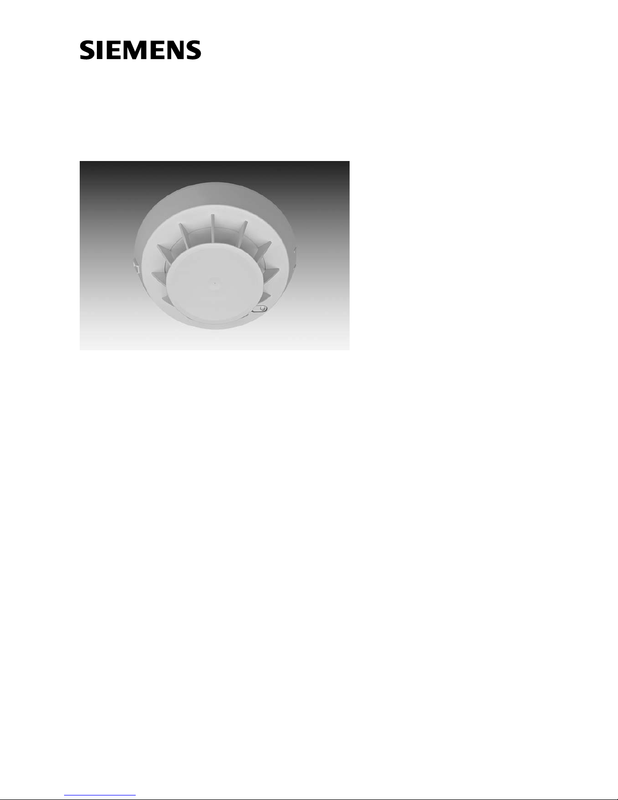
Synovat Fire detection system
HI320C / HI322C
Heat detectors
Description
Page 2

Data and design subject to change
without notice. / Supply subject to
availability
.
E Copyright by
Siemens Schweiz AG
Wir behalten uns alle Rechte an
diesem Dokument und an dem in ihm
dargestellten Gegenstand vor. Der
Empfänger anerkennt diese Rechte
und wird dieses Dokument nicht ohne
unsere vorgängige schriftliche
Ermächtigung ganz oder teilweise
Dritten zugänglich machen oder
ausserhalb des Zweckes verwenden,
zu dem es ihm übergeben worden ist.
We reserve all rights in this document
and in the subject thereof. By
acceptance of the document the
recipient acknowledges these rights
and undertakes not to publish the
document nor the subject thereof in
full or in part, nor to make them
available to any third party without our
prior express written authorization,
nor to use it for any purpose other
than for which it was delivered to him.
Nous nous réservons tous les droits
sur ce document, ainsi que sur l’objet
y figurant. La partie recevant ce
document reconnaît ces droits et elle
s’engage à ne pas le rendre
accessible à des tiers, même
partiellement, sans notre autorisation
écrite préalable et à ne pas
l’employer à des fins autres que
celles pour lesquelles il lui a été
remis.
Ci riserviamo ogni diritto relativo al
presente documento e sull’oggetto
illustrato in esso. La parte che riceve
il documento si impegna a non
renderlo accessibile a terzi, né per
intero né in parte, senza la nostra
previa autorizzazione scritta ed a non
usarlo per altri scopi di quello per il
quale è stato rilasciato.
Page 3

Fire Safety & Security Products
Building Technologies 10.2005
I
1 General 1 . . . . . . . . . . . . . . . . . . . . . . . . . . . . . . . . . . . . . . . . . . . . . . . . . . . . . . . . . .
1.1 Characteristics 1 . . . . . . . . . . . . . . . . . . . . . . . . . . . . . . . . . . . . . . . . . . . . . . . . . . . .
1.2 Construction 2 . . . . . . . . . . . . . . . . . . . . . . . . . . . . . . . . . . . . . . . . . . . . . . . . . . . . . .
2 Technical data 3 . . . . . . . . . . . . . . . . . . . . . . . . . . . . . . . . . . . . . . . . . . . . . . . . . . . .
3 Design 4 . . . . . . . . . . . . . . . . . . . . . . . . . . . . . . . . . . . . . . . . . . . . . . . . . . . . . . . . . . .
4 Response characteristics 5 . . . . . . . . . . . . . . . . . . . . . . . . . . . . . . . . . . . . . . . . . .
5 Application 5 . . . . . . . . . . . . . . . . . . . . . . . . . . . . . . . . . . . . . . . . . . . . . . . . . . . . . . .
5.1 Compatibility 5 . . . . . . . . . . . . . . . . . . . . . . . . . . . . . . . . . . . . . . . . . . . . . . . . . . . . . .
5.2 Adjustment functions 5 . . . . . . . . . . . . . . . . . . . . . . . . . . . . . . . . . . . . . . . . . . . . . . .
5.3 Application 5 . . . . . . . . . . . . . . . . . . . . . . . . . . . . . . . . . . . . . . . . . . . . . . . . . . . . . . . .
5.4 Installation 6 . . . . . . . . . . . . . . . . . . . . . . . . . . . . . . . . . . . . . . . . . . . . . . . . . . . . . . . .
6 Commissioning 6 . . . . . . . . . . . . . . . . . . . . . . . . . . . . . . . . . . . . . . . . . . . . . . . . . . .
7 Maintenance 6 . . . . . . . . . . . . . . . . . . . . . . . . . . . . . . . . . . . . . . . . . . . . . . . . . . . . . .
7.1 Functional check / overhaul 6 . . . . . . . . . . . . . . . . . . . . . . . . . . . . . . . . . . . . . . . . .
Page 4

Fire Safety & Security Products
Building Technologies
II
10.2005
Page 5
Fire Safety & Security Products
Building Technologies
1703_d_en_−−
1
10.2005
1 General
36
Ø 100
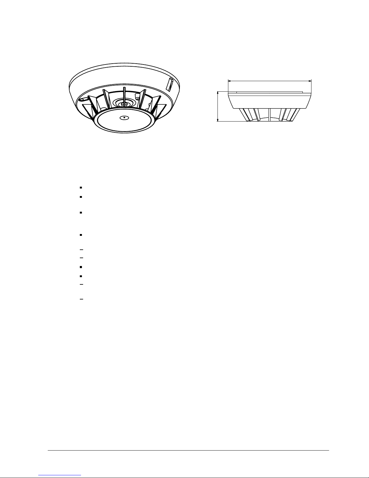
HI320C/HI322C with base SO320
Dimension
1.1 Characteristics
Heat detectors to meet the highest requirements
HI320C Heat detector class A1R,
with wide application range, rate of rise and maximum behaviour
HI322C Heat detector class A2
with rate of rise and maximum temperature activation ,
for areas with higher temperature fluctuation
Response behaviour immune to deceptive phenomena with rapid and slow
increase in temperature through:
Intelligently designed differential characteristics
Precise maximum temperature alarm activation with quality thermosensor
High degree of reliability and long-term stability
High resistance to:
Electromagnetic interference (EMI)
through protected signal lines and shielded circuit
Humidity and corrosion
Page 6

Fire Safety & Security Products
Building Technologies
1703_d_en_−−
2
10.2005
1.2 Construction
The HI320C/HI322C are built into a modern, impact-proof plastic housing which
blends unobtrusively in any room. They are inserted into the connector of the base
SO320.
The built-in response indicator (red LED), provides an on-site alarm signal. Two
additional external response indicators can be connected to the base.
The detectors are fully electronic and are not subject to wear and tear. The protective
cover can be easily removed for cleaning, should the case arise.
The SO320 detector base is mounted on the ceiling or onto the base attachment
SOA322 in case of surface-mounted wiring and connected to the control unit via twin
wire. The base is fitted with screwless spring terminals for connection.
Page 7

Fire Safety & Security Products
Building Technologies
1703_d_en_−−
3
10.2005
2 Technical data
Normal ambient conditions, if nothing else is specified:
Temperature T
a
= 20°C (293K)
Air pressure: p
= 1’000hPa (1’000mbar)
Value
Parameters Symbol Unit min. typ. max. Conditions
Operating voltage
(quiescent condition)
U
b
V 16 28 normal operation or
alarm condition
Max. permissible voltage U
max.
V 28 normal operation or
alarm condition
Operating current
(quiescent condition)
I
b
µA 100 normal operation
Alarm Resistance
in series to 1.5V incl. internal
alarm indicator
R
A
Ω 410 450
in alarm condition,
no remote indicator
connected
Alarm reset voltage U
R
V 1 6
Alarm reset current I
R
mA 10
Alarm reset time t
R
s 1 UR = 1V
Response sensitivity
HI320C
EN 54-5 class A1R
temperature increase
Release temperature,static
dT
T
a
°C
°C
20
54
40
62
dT/dt=10K/min.
dT/dt=0.2K/min.
HI322C
EN 54-5 class A2
Release temperature,static
Release temperature,dynamic
dT
T
a
°C
°C
54
70
70 dT/dt=0.2K/min.
dT/dt=10K/min.
Remote response indicator
output current (DC)
mA 10 in alarm condition;
total current, one or two
indicators connected
Remote indicator output
impedance
1.5V in
series to
1kΩ
in alarm condition
Electromagnetic compatibility V/m 50 1MHz...1GHz
Operating temperature T
a
°C −10 +50
Humidity %rH <100
Storage temperature T
l
°C −20 +65
Connection factor 1 SynoLINE300
Colour: white ~RAL9010
Classification
Standards HI320C: EN 54-5 class A1R
HI322C: EN 54-5 class A2
Application category IEC 60721-3: 3K5
Test category IEC 60068-1: 10/050/21 (EN 54-5)
Protection category IEC 60529: IP44
CE mark of conformity yes
Page 8
Fire Safety & Security Products
Building Technologies
1703_d_en_−−
4
10.2005
3 Design
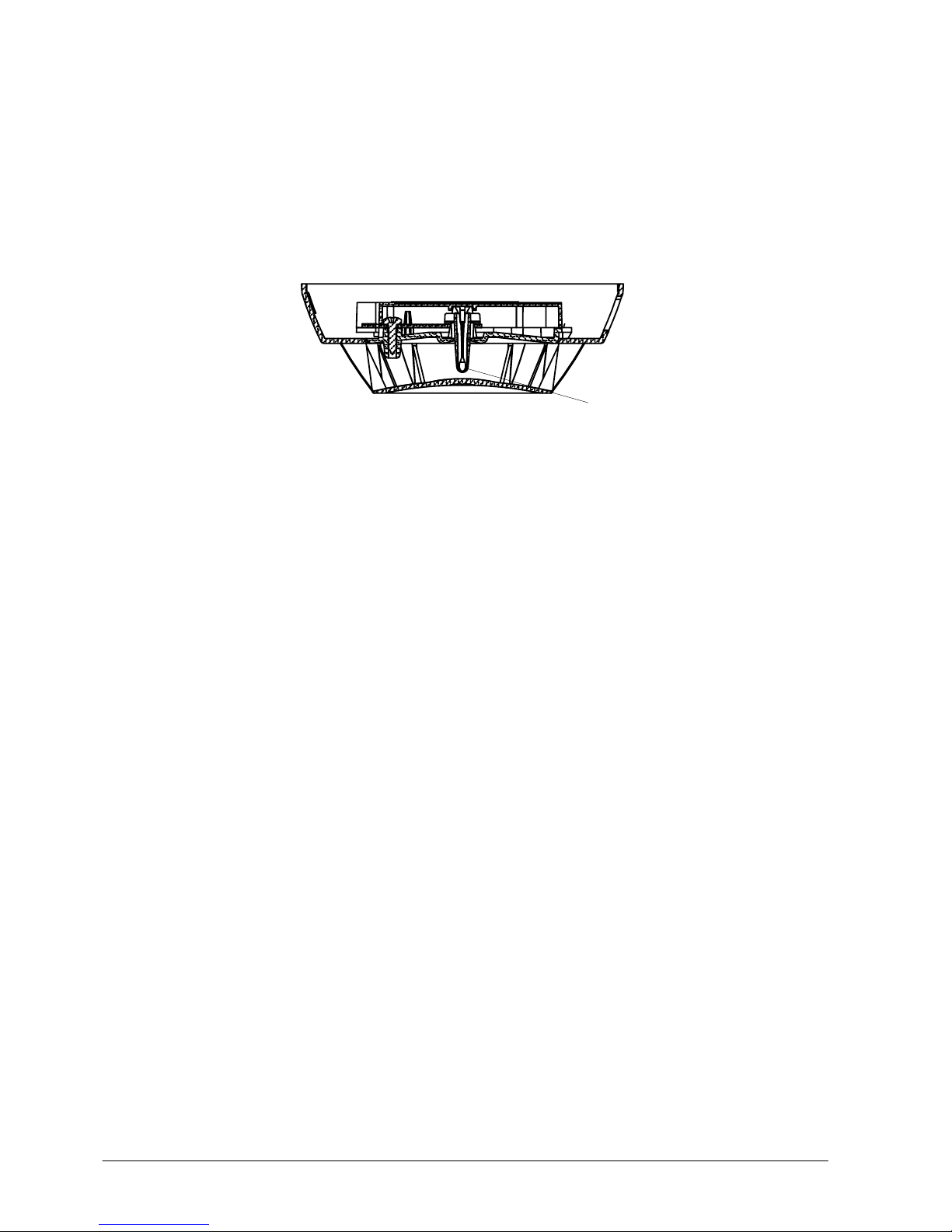
The temperature sensor of the HI320C/HI322C consists of two precision NTC
thermistors, which are attached to a holder. The measuring resistor R
m
is located in
the tip of the protection cover and measures the ambient temperature. The housing
temperature is measured with resistor R
g
.
The open protection housing means that the ambient temperature has an almost unhindered effect on the sensor and protects it against mechanical damage.
NTC Temperature sensors
Fig. 1 Detector design
Page 9

Fire Safety & Security Products
Building Technologies
1703_d_en_−−
5
10.2005
4 Response characteristics
The HI320C complies with European standard EN 5 4-5 class A1R (60°C rate−of−rise
and maximum).
The HI322C complies with European standard EN 54-5 class A2 (70°C rate−of−rise
and maximum).
5 Application
5.1 Compatibility
Detection lines: SynoLINE300
Base: SO320
5.2 Adjustment functions
None.
5.3 Application
The HI320C/HI322C can be used up to a temperature of 50°C and are especially
suitable for monitoring rooms and installations in which in the event of fire, a rapid
increase in temperature is to be expected, or where other types of detector cannot be
used because work processes cause smoke, dust, exhaust gases etc.
Page 10
Fire Safety & Security Products
Building Technologies
1703_d_en_−−
6
10.2005
5.4 Installation
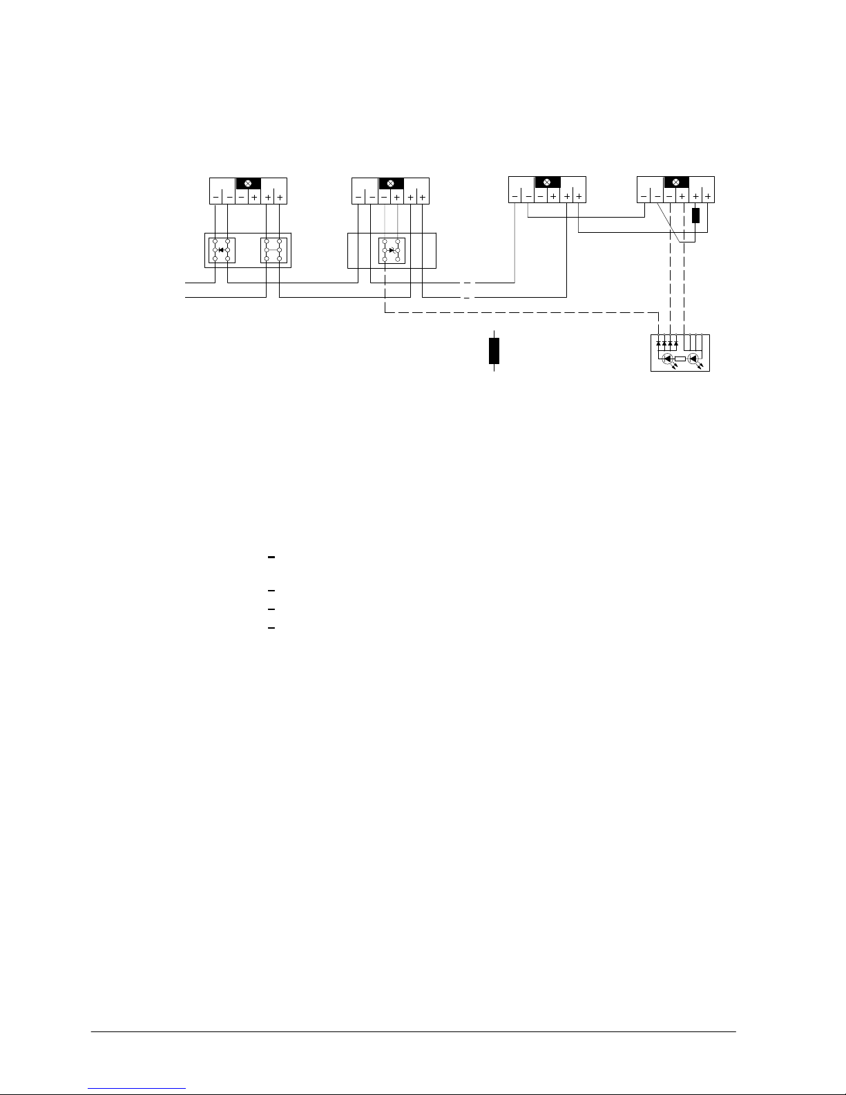
Bases are connected together by twin wire. Shielded cable is only required for special applications, e.g. in the case of powerful high frequency fields.
Up to 32 HI320C/HI322C may be connected per line depending on specifications of
the line card in the control panel.
Control unit
Line termination
according to control unit
SO320
SO320
Response
+−
SO320
−
+
indicator
AI320
AI322
Accessories:
Base attachment, auxiliary terminals,
detector locking device and
commissioning module
see installation instructions x1684
SO320
SOA322
1)
Option
Lightning
protection
2)
Option
Bypass
Fig. 2 Connection diagram
2)
If manual call points are used on the same line.
6 Commissioning
In order to avoid soiling the detectors unnecessarily, only insert them in the bases
immediately prior to commissioning.
Activate detectors with detector tester RE6T.
If the response indicator at the detector lights up, the detector is operating correctly.
The line test set DZ1 195 can be used for the final testing of installed detection lines.
7 Maintenance
7.1 Functional check / overhaul
A functional check of the detectors must be performed periodically by forcing each
detector to respond by means of a suitable testing device (e.g. RE6T). Recommen-
dation: Once a year, unless otherwise specified by local regulations. Detectors that
do not respond or which are mechanically damaged must be replaced.
All detectors should be replaced and factory overhauled in intervals of 6 to 12 years,
depending on the environmental conditions and the severity of contamination. Consider possible national regulations.
If mechanically damaged detectors must be scrapped, the plastic materials can be
sorted out based on the embossed code.
Page 11

Fire Safety & Security Products
Building Technologies
Back
7
10.2005
Page 12

Fire Safety & Security Products
Building Technologies
Back
8
10.2005
Document no.
Edition
1703_d_en_−−
10.2005
International Headquarters
Gubelstrasse 22
Fire Safety & Security Products
CH-6301 Zug
Manual
Section
DS11.1
2
Siemens Schweiz AG
Building Technologies Group
Tel.
Fax
www.sbt.siemens.com
+41 41 724 24 24
+41 41 724 35 22
 Loading...