

Siemens GENESIS II Installation Manual
009159_a_en_--.doc 1
Building Technologies
Fire & Security Products
GENESIS II
Installation Manual
and
Technical Data
Control panel with
one fire detection zone,
associated
an intrusion
and/or
hold-up-system
Installation manual 009159_a_en_-Edition 10.11.2005
Supersedes -
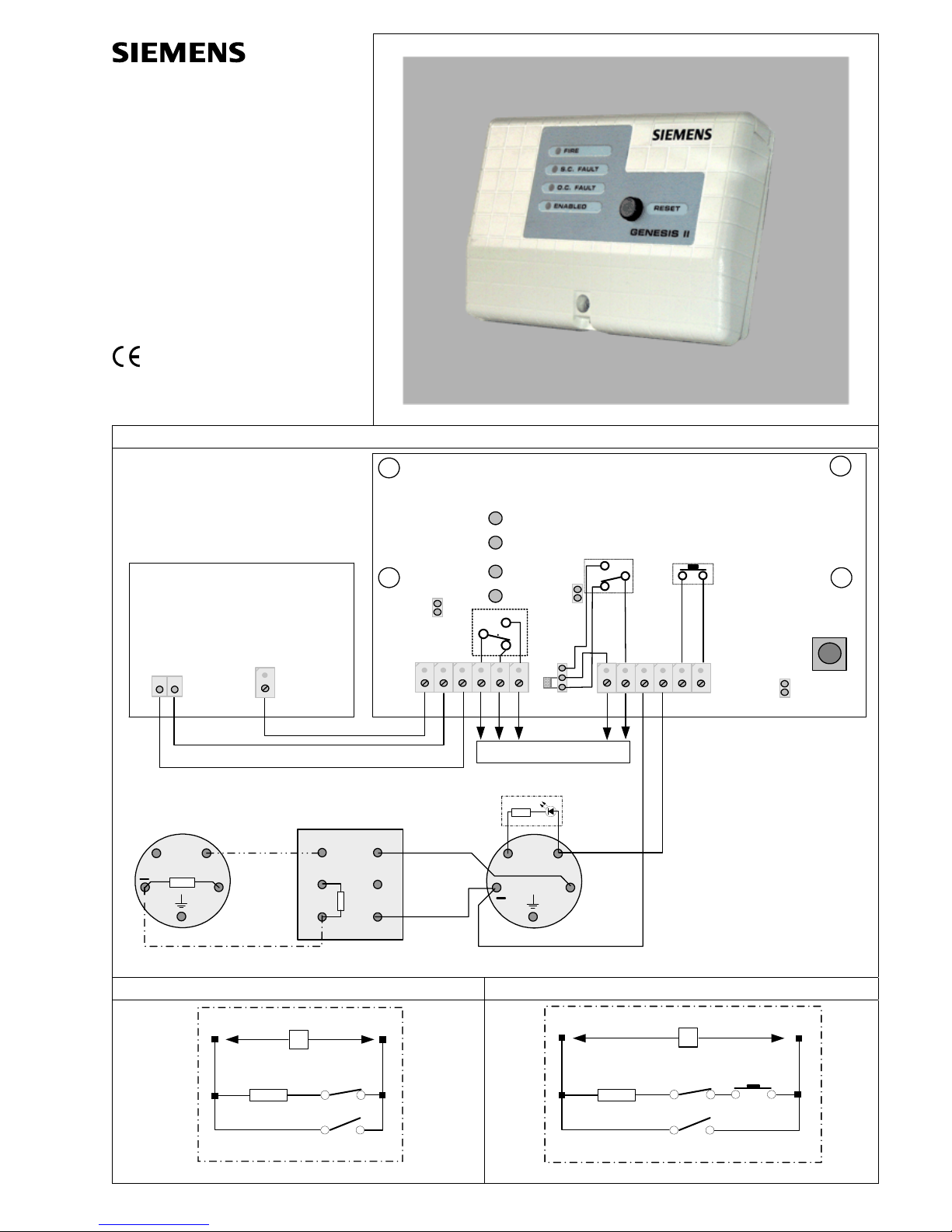
1
PU4
PU1
PU2
PU3
GENESIS II MODULE
DL2
DL3
DL4
DL1
GENERAL MODULE
INTRUSION CONTROL
PANEL
Out
In-R
2K7
REOL
Detector
Socket
Out
In-R
Detector
Socket
-
+
R470/1W
Call Point
- LINE
+LINE
-
+
CONT
Activity LED
max. 20mA
-
+
OUT >5mA
POWER SUPPLY
12V
FAULT
ALARM
TAMPER
for details see Fig. 2, 3
12V
CONTROL
NC
NO
See description for Indicators and Jumpers
2 3
R
NC
NO
1
Fault
Alarm
Alarm and fault outputs to one zone of the Intrusion Control Panel (1)
R
NC
NO
1
T
Fault
Alarm
Tamper
Alarm and fault outputs (tamper incl.) to one zone of the Intrusion Control Panel(1)
2 009159_a_en_--.doc
Instructions for use the GENESIS II Control Panel
Overview
The GENESIS II, makes it possible to install singlezone fire detection based on a conventional intrusion
detection control panel, controlling and supervising a
2-wire line, equipped with up to 32 conventional detectors at 24Vdc.
The GENESIS II is supplied with 13.8Vdc from the
intrusion control panel and, by means of an internal
converter, is able to provide the 24Vdc supply required by the detectors and/or call points. This eliminates the need for an external 24Vdc power supply
and battery backup, as in the case of mains failure /disconnection, the intrusion control panel backup
powers the system.
Jumper settings
Description ON OFF
Non current limited detectors PU1
PU2
Current limited detectors PU1
PU2
Fault Output C-NC PU3
(2,3)
Fault Output C-NO PU3
(1,2)
Local Control
(Push button GENESIS II)
PU4
Remote control
(from Intrusion control panel)
PU4
LED displays
LED Colour Description
DL1 Green Enable LED
DL2 Red Fire LED
DL3 Amber Short Circuit fault LED
DL4 Amber Open Circuit fault LED
Wiring
Power supply and control.
GENESIS II has two control possibilities, depending
on the fact that the Intrusion Control Panel has an
output for sensors rearming or not.
Follow the steps detailed here below:
– Carry the supply (11 to 14Vdc) from the Intrusion
Control Panel to the terminals designated (-12V+)
of GENESIS II.
– If the Intrusion Control Panel does not include the
aforementioned output for detectors rearming, the
control on GENESIS II will be carried out from the
reset push-button itself (make sure that the PU4
jumper has been inserted).
– In case the Intrusion Control Panel has the output
available, wire it at the input of the terminals input
labelled (CONT) of GENESIS II. It will be reset
when it detects a level of 0V in that control input;
this implies a rearming in the detectors line if that
level is present during the period required by the
detectors (3 to 4 seconds is usually enough for
most of them). To have this feature available, you
must remove the PU4.
Detectors and/or call points line.
Connect the detectors (ionizing, optical, etc) and/or
call points line to (+LINE-) as shown in fig.1.
The GENESIS II allows both current-limited
and non-current-limited detectors and/or call
points provided that the two types are not
mixed on the same line.
Setup
Set up the GENESIS II according to the type used as
follows:
Non-current-limited detectors and/or call points:
Remove GENESIS II jumpers PU1 and PU2.
See Fig.1
Compatibility with the non-current detectors below:
– DL0 beam detector
– DF1191/92 infrared flame detector
Current-limited detectors and/or call points
Insert GENESIS II jumpers PU1 and PU2.
See Fig.1
Compatibility with the current detectors below:
– OP320C optical detector
– OH320C multi detector
– HI320C heat detector
– HI322C heat detector
– MT320C manual call point
Alarm and fault output
It incorporates alarm and fault outputs by means of
voltage-free relay contacts, what facilitates its adaptation to the different Intrusion Control Panels, regards to connection.
Figures 2 and 3 show, as an example, 2 types of
connection, among the most common ones, used for
this kind of installations:
– Figure 2 presents a typical connection for the iden-
tification of alarm and fault on the detectors line of
GENESIS II, in two independent zones associated
to the Intrusion Control Panel.
– In those Intrusion Panels with EOL resistor in each
zone, being possible to program some of them as
“fire zone” so that a short-circuit or open-circuit in
that zone will be identified as fire alarm or fault, respectively, the wiring can be done as shown in
fig.3, which includes an electrical diagram for a
better comprehension.
– In addition to the connection shown in figure 2,
fig.3 presents the possibility of tamper detection on
the part of the GENESIS II box.
Functional test
Before testing the installation ensure that the power
supply polarity is correct. Also, check that jumpers
PU1 and PU2 are in the correct positions according
to the type of detectors used in the installation.
Next, connect the GENESIS II to power and check
that the green “ENABLED” led is lit and that the Intrusion Control Panel is in standby mode.
Open-circuit fault.
– Disconnect the 2K7 end of line resistor. The amber
“OC FAULT” led on the GENESIS II will be lit and
the Intrusion Control Panel indicate fault on the
corresponding zone.
– Reconnect the resistor. The indicator will go out.
– Remove each of the detectors from their sockets
one at a time (the line will open as each is re-
moved provided the standard mounting instruc-
tions for the detectors have been followed). Check
that unit in exactly the same was as described in
the previous paragraph.
Short-circuit fault
– Short-circuit the 2K7 end of line resistor. The am-
ber “SC FAULT” led on the GENESIS II will be lit
and the Intrusion Control Panel will indicate fault
on de corresponding zone. Remove the short-
circuit. The indicator will go out.
Alarm
– Now activate each detector by means of the effect
it is designed to detect (smoke, rapid temperature
rise, manual call point activation etc). The indicator
on the detector will be lit, as will the “ALARM” led
on the GENESIS II. The Intrusion Control Panel
will indicate alarm on the corresponding zone.
Resetting the detector lines
– From the reset push-button of GENESIS II, or from
a sensors rearming output, in case the Intrusion
Control Panel allows it, cause a 3 seconds rearm-
ing approximately in the detectors line, checking
that during this period of time, the “ENABLED”
LED of GENESIS II will go out, so that if the cause
that originated the activation of the detectors has
disappeared, the detectors will go back to standby
condition.
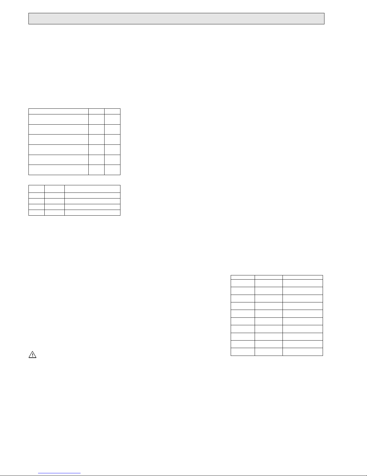
Technical data
General features
Dimensions in mm
(wide x height x depth)
134 x 85 x 27cm
Aprox. Weight (gr.) 125gr
Temperature and relative humidity
without condensation.
00 - 500C
10% - 90%
Standards CE
EN50130-4 9
EN61000-6-3 9
89/336/EEC 9
93/68/EWG 9
Electrical features
Supply voltage 11 - 14V.
Stand-by consumption
(with no detectors)
35 - 45mA
Max. consumption <200mA
Establishment timing since rearming <500ms.
Delay timing of alarm signal <300ms
Output features
Alarm output by voltage-free contacts
C NO NC
30Vd.c. 1A
Fault output by voltage-free contacts
C-NO or C-NC
30Vd.c. 1A
Line characteristics for PU1 and PU2
for non-current-limited detectors OFF
Power supply voltage 11 - 14V
Line voltage with detectors in stand-by, 17.5 - 22.5V
Line voltage in alarm condition 6 - 10V.
Line consumption to indicate alarm 18 - 56mA.
Line consumption to indicate shortcircuit.
59 - 65mA
Line consumption to indicate opencircuit
<4mA
Maximum consumption of stand-by
detectors
<4mA
End-of-line resistor 2K7 Ohm 1/2W
+/-10%
Line characteristics for PU1 and PU2
for current-limited detectors ON
Line voltage with detectors in stand-by 11 -14V
Line voltage in alarm condition 18.5 - 24V
Line consumption to indicate alarm 17 - 22.5V
Line consumption to indicate shortcircuit.
25 - 58mA
Line consumption to indicate opencircuit
60 - 75mA
Maximum consumption of stand-by
detectors
<4mA
End-of-line resistor 2K7 Ohm 1/2W
+/-10%
Details for ordering
Type Part no Designation
MGEN2 9300170001 Fire detection panel
PCB
GEN2-DE 9300150001 Fire detection panel
German
GEN2-EN 9300110001 Fire detection panel
English
GEN2-ES 9300100001 Fire detection panel
Spanish
GEN2-PL 9300090001 Fire detection panel
Polish
GEN2-IT 930012.0-001 Fire detection panel
Italian
GEN2SV(SE)
9300130001 Fire detection panel
Swedish
GEN2-FR) 9300180001 Fire detection panel
French
GEN2-NL 9300190001 Fire detection panel
Netherlands
GEN2-NO 9300140001 Fire detection panel
Norwegian
 Loading...