

Page 1

FLUOROSPOT H/HK
RX
Installation and Setting Instructions
Options
Memory Expansion (Mass Memory Upgrade)
Display Plus (High-Speed Refresh Video)
Image Winchester upgrade for at least 300 Images
Image Winchester upgrade for at least 1000 Images
(1 GB Disk)
Digital Optic a l D is k
Peripheral Angiography
© Siemens AG 1995
The reproduction, transmission or
use of this document or its contents
is not permitted without express
written authority. Offenders will be
liable for damages. All rights,
including rights created by patent
grant or registration of a utility
model _or_ design,_are_ reserved.
Register 3 English
Print No.: RX41-020.033.04.05.02 Doc. Gen. Date: 09.96
Replaces: RX41-020.033.04.03.02
Page 2

0 - 2Revision
Chapter Page Revision
01 to 404
11 to 603
21 to 403
31 to 602
41 to 204
51 to 402
61 to 404
71 to 201
01 to 405
11 to 604
21 to 404
31 to 603
41 to 205
51 to 403
61 to 405
71 to 202
FLUOROSPOT H/HK Register 3 RX41-020.033.04 Page 2 of 4 Siemens AG
Rev. 05 09.96 TD AX 5 Medical Engineering
Page 3

Contents 0 - 3
Page
1 _______Memory Expansion (Mass Memory Upgrade)________________________ 1 -1
Documents required. . . . . . . . . . . . . . . . . . . . . . . . . . . . . . . . . . . 1 -1
Measuring instruments and device s required . . . . . . . . . . . . . . . . . . . . . . 1 -1
Installing memory expansion in the IPS. . . . . . . . . . . . . . . . . . . . . . . . . 1 -1
If mass memory board is already present in the IPS and combined with 16 MB boards 1 -1
If no mass memory board is present in the IPS but there is an open IPS slot available 1 -3
If no mass memory board is present in the IPSand there is no open IPS slot available 1 -3
Addressing of the memory boards (16 MB boards/mass memory board). . . . . . . . 1 -4
Mass memory board. . . . . . . . . . . . . . . . . . . . . . . . . . . . . . . . . . . 1 -6
2 _______Display Plus (High Refresh Video)_________________________________ 2 -1
High-speed refresh parts list . . . . . . . . . . . . . . . . . . . . . . . . . . . . . . :2 -1
Installing the high refresh key . . . . . . . . . . . . . . . . . . . . . . . . . . . . . . 2 -2
System configuration . . . . . . . . . . . . . . . . . . . . . . . . . . . . . . . . 2 -2
Calibrating the video output board III . . . . . . . . . . . . . . . . . . . . . . . . . . 2 -2
Checking the configuration of the SIMOMED-H monitors. . . . . . . . . . . . . . . . 2 -3
Settings and Configuration with SIMOMED HM Monitors. . . . . . . . . . . . . . . . 2 -3
Switching off the external light sensor. . . . . . . . . . . . . . . . . . . . . . . . 2 -3
Blocking Norms (4:3 screen fo rm at). . . . . . . . . . . . . . . . . . . . . . . . . 2 -4
Adjusting Luminous Intensity in 50/60Hz Syst ems with Display Plus . . . . . . . . . . 2 -4
Concluding work. . . . . . . . . . . . . . . . . . . . . . . . . . . . . . . . . . . . . 2 -6
3 _______Image Winchester Upgrade for at least 300 Images___________________ 3 -1
SCSI Image Winchester Upgrade Parts List . . . . . . . . . . . . . . . . . . . . . . 3 -1
FLUOROSPOT . . . . . . . . . . . . . . . . . . . . . . . . . . . . . . . . . . . . . 3 -1
Installing the SCSI Control Board
(50070 - 0003 or 50109 - 0003) . . . . . . . . . . . . . . . . . . . . . . . . . . . . . 3 -2
Installing the Image Winchester drive . . . . . . . . . . . . . . . . . . . . . . . . . . 3 -4
System Configuration . . . . . . . . . . . . . . . . . . . . . . . . . . . . . . . . . . 3 -4
Directory Reset Operation. . . . . . . . . . . . . . . . . . . . . . . . . . . . . . . . 3 -5
4 _______Image Winchester Upgrade for at least 1000 Images__________________ 4 -1
This procedure describes the replacement of a 300/400 images
Winchester Drive with a 1GB Winchester Drive. . . . . . . . . . . . . . . . . . . . . 4 -1
Replacing the Winchester hard disk drive. . . . . . . . . . . . . . . . . . . . . . . . 4 -1
Switch and Jumper settings SCSI EDMA Board (50109-0003) . . . . . . . . . . . . . 4 -2
Resetting Winchester directory . . . . . . . . . . . . . . . . . . . . . . . . . . . . . 4 -2
Concluding work. . . . . . . . . . . . . . . . . . . . . . . . . . . . . . . . . . . . . 4 -2
5 _______Digital Optical Disk (DOD) _______________________________________ 5 -1
DOD option parts list . . . . . . . . . . . . . . . . . . . . . . . . . . . . . . . . . . 5 -1
General Remarks . . . . . . . . . . . . . . . . . . . . . . . . . . . . . . . . . . . . 5 -1
Siemens AG Register 3 RX41-020.033.04 Page 3 of 4 FLUOROSPOT H/HK
Medical Engineering Rev. 04 09.96 TD AX 5
Page 4

0 - 4 Contents
Page
Installing the DOD interface boar d . . . . . . . . . . . . . . . . . . . . . . . . . . . .5 -1
Switch and jumper settings for DOD interface board. . . . . . . . . . . . . . . . . . .5 -2
Installing the DOD assembly . . . . . . . . . . . . . . . . . . . . . . . . . . . . . . .5 -3
Miscellaneous . . . . . . . . . . . . . . . . . . . . . . . . . . . . . . . . . . . . . .5 -3
6 ______ Peripheral Angiography _________________________________________ 6 -1
Peripheral Angiography parts list. . . . . . . . . . . . . . . . . . . . . . . . . . . . .6 -1
Installing the Peripheral Angiography key . . . . . . . . . . . . . . . . . . . . . . . .6 -1
System Configuration FLUOROSPOT H . . . . . . . . . . . . . . . . . . . . . . . . .6 -1
Table-specific changes . . . . . . . . . . . . . . . . . . . . . . . . . . . . . . . .6 -2
Generator-specific changes . . . . . . . . . . . . . . . . . . . . . . . . . . . . .6 -2
Test . . . . . . . . . . . . . . . . . . . . . . . . . . . . . . . . . . . . . . . . . . . .6 -3
Conclusion . . . . . . . . . . . . . . . . . . . . . . . . . . . . . . . . . . . . . . . .6 -3
7 ______ Changes to Previous Version_____________________________________ 7 -1
FLUOROSPOT H/HK Register 3 RX41-020.033.04 Page 4 of 4 Siemens AG
Rev. 04 09.96 TD AX 5 Medical Engineering
Page 5

NOTICE
CAUTION
NOTICE
Memory Expansion (Mass Memory Upgrade) 1
Documents required 1
• FLUOROSPOT H Service Manual 8999-0031
• POLYDOROS 50/80S Speed Info 106/ 91 RX67-010.1 17.01.05.01*
• Polydoros SX System Configuration starting
from VC00B (XX= depending on current software
version)
* Documents only for Peripheral Angiography Option nece ssary
Measuring instruments and devices required 1
• Service PC according specifications in the ARTD 001.719.06.02.05
• ST 320 terminal emulation 97 04 586 Y 4364
• Oscilloscope>50MHz with delayed time base and
retriggering of the 2nd ti me base (only necessary for
Display Plus option)
• Tool kit 97 02 457 Y 1971
RX63-050.034.XX...*
1 - 1
The maximum memory capacity with software version VD11 is
192 MB (two mass memory boards fully equipped). The maximum
capacity of one mass memory board is 96 MB.
Combinations of 16 MB boards and a mass memory board are
possible as well. The maximum memory capacity is then 160 MB
(4x16 MB boards + 1 mass memory board with 96 MB) depending
on free slots in the IPS.
Installing memory expansion in the IPS 1
• Remove the front panel of the FLUOROSPOT H/HK cabinet.
• Make sure the power is either completely disconnected or i s turned off at the AC power
distribution system in th e cabinet.
- Remove the inside cover
Electrostatically-sensitive parts inside. Do not remove or install
boards with power ON. Always use proper electrostatic protection methods when removing or installing boards.
If mass memory board is already present in the IPS and
combined with 16 MB boards
• Remove the mass memory board from the IPS.
The memory must be expanded in 16 MB increments. One 16 MB
increment = 4 memory modules.
Siemens AG Register 3 RX41-020.033.04 Page 1 of 6 FLUOROSPOT H/HK
Medical Engineering Rev. 04 09.96 TD AX 5
1
Page 6

1 - 2Memory Expansion (Mass Memory Upgrade)
NOTICE
NOTICE
• Insert the number of 16 MB memory increments desired into the mass memory board,
starting with the lowest sec tion number available (see also page 1-6).
• Return the mass memory board into the same IPS slot from which it was remov ed. No
switch changes are necessary.
• Connect the service PC and enter service mode.
• Go into the system configuration menu and change the number of 16 MB modules to t he
correct number (16 MB boards + 16 MB increments = number of 16 MB modules).
• If only one mass memory board is present in the IPS1.
1. Remove the mass memory board from the IPS
The memory must be expanded in 16 MB increments. One 16 MB
increment = 4 memory modules.
2. Insert the number of 16 MB memory increments desir ed into the mass memory
board, starting with the lowest section number available(see also page 1-6) .
3. Return the mass memory board into the same s lot from which it was removed. No
switch changes are necessary.
4. For the memory expansion > 96 MB, a second mass memory board i s necessary.
In the IPS, move all the boards on the r ight side of the mass memory board one
slot to the right.Expand the second mass memor y board with 16 MB memory
increments as described under step 2. Addr ess the second mass memory board
as described on page 1-5.Insert t he mass memory board into the open IPS slot to
the right of the already existi ng mass memory board
If you have Mass Memory Boards with different Revision Levels
(50107-0002B and C) the board with level B must be switched to
address 1 and has to be installed at left side of the Mass Memory
Rev.C. The left board (Rev.B) has to be fully equipped.
5. Connect the service PC and enter service mode.
6. Go into the system configuration menu and change the number of 16 MB modules
to the correct number.
7. Exit menu, save and reboot the system.
FLUOROSPOT H/HK Register 3 RX41-020.033.04 Page 2 of 6 Siemens AG
Rev. 04 09.96 TD AX 5 Medical Engineering
Page 7

Memory Expansion (Mass Memory Upgrade) 1 - 3
NOTICE
NOTICE
NOTICE
If no mass memory board is present in the IPS but there is an
open IPS slot available
The memory must be expanded in 16 MB increments. One 16 MB
increment = 4 memory modules.
• Insert the number of 16 MB memory increments desired into the mas s memory board,
starting with the lowest secti on number available (see also page 1-6).
• In the IPS, move all the boards on the right side of the 16 MB memory boards one slot to
the right.
• Set switch settings on the mass memory board as shown on page 1-5. Inse rt the board
into the open IPS slot to the right of the 16 MB boards.
• Connect the service PC and enter service mode.
• Go into the system configuration menu and change number of 16 MB modules to the
correct number (16 MB boards + 16 MB increments = number of 16 MB modules).
• Exit menu, save, reboot the system.
If no mass memory board is present in the IPSand there is no
open IPS slot available
• If the reason for a memory expansion is only to get more RAM capaci ty, then it is only
necessary to remove the 16 MB memory board furthest to the right.The 16 MB board is
replaced by the mass memory board. Continue wi th step 2.
1
1
• If the reason for a memory expansion is to get one more slot for an option (Sienet,
DOD..) or to get one more slot for an option and additional RAM capacity, continue wit h
step 1.
1. The number of open IPS slots needed determines how many 16 MB boards have
to be removed. Refer to the chart bel ow.
4X
3X
Number of IPS
slots needed
2. Starting with section 1 on the mass memory boar d, insert the number of 16 MB
increments that equals the number of 16 MB boards that were removed from the
IPS (see also page 1-6.
2X
1X
12345
Tab. 1
Number of 16 MB boards to be removed
When removing 16 MB boards from the IPS PC board rack, start
with the 16 MB b o a rd fu rthest to the right .
One 16 MB increment = 4 memory modules
Siemens AG Register 3 RX41-020.033.04 Page 3 of 6 FLUOROSPOT H/HK
Medical Engineering Rev. 04 09.96 TD AX 5
Page 8

1 - 4Memory Expansion (Mass Memory Upgrade)
NOTICE
3. Starting with the lowest secti on number available on the mass memory board,
insert the number of 16 MB memory increments des ired to expand the memory
capacity of the IPS (see also page 1- 6).
If any 16 MB boards are still in the system, the mass memory
board must be inserted in the IPS slot to their right.
4. Set switch settings on the mass memory boar d as shown on page 1-5, and insert
the board into the IPS.
5. If there are any open slots in the IPS bet ween boards, move all boards to the left
so that no open slots exist.
6. Connect the service PC and enter service mode.
7. Go into the system configuration menu and change number of 16 MB modules to
the correct number (16 MB boards + 16 MB increments = number of 16 MB
modules).
8. Exit menu, save, and reboot the syst em.
Addressing of the memory boards (16 MB boards/mass memory
board)
If the mass memory board and 16 MB boards are used in the same system, then the
mass memory board must be in the memory slot furthest to the right. The 16 MB boards
must be addressed below the mass memory board.
Each 16 MB board is addressed as a memory module (DIP switch configuration on the
memory board).
The 16 MB memory modules are numbered consecutively starting from 1. The address of
a mass memory board corresponds to the number of the 16 MB memory modules with
which the mass memory board starts.
Example 1:
3x16 MB boards and one mass memory board are present in the IPS
The first 16 MB board is addressed as memory module #1.
The second 16 MB board is addressed as memory module #2.
The third 16 MB board is addressed as memory module #3.
The mass memory board is addressed as memory module #4.
Example 2:
2 mass memory boards are present in the IPS.
The first mass memory board is equipped with 6x16 MB modules, the second
mass memory board with 3x16 MB modules.
1
The first mass memory board is addressed as memory module #1.
The second mass memory board is addressed as memory module #7.
FLUOROSPOT H/HK Register 3 RX41-020.033.04 Page 4 of 6 Siemens AG
Rev. 04 09.96 TD AX 5 Medical Engineering
Page 9

Memory Expansion (Mass Memory Upgrade) 1 - 5
NOTICE
Memory module # 1 Memory module # 2
Number Position Number Position
SW 1 1 OFF SW 1 1 ON
2ON 2 OFF
3ON 3 ON
4ON 4 ON
Memory module # 3 Memory module # 4
Number Position Number Position
SW 1 1 OFF SW 1 1 ON
2OFF 2 ON
3ON 3 OFF
4ON 4 ON
Memory module # 5 Memory module # 6
Number Position Number Position
SW 1 1 OFF SW 1 1 ON
2ON 2 OFF
3 OFF 3 OFF
4ON 4 ON
Memory module # 7
Number Position
SW 1 1 OFF
2OFF
3OFF
4ON
There is a misprint in the CAMTRONICS MANUAL (2/17/94) for
memory modules #6 and #7 (page 5-10).
The setting on this page is correct.
Siemens AG Register 3 RX41-020.033.04 Page 5 of 6 FLUOROSPOT H/HK
Medical Engineering Rev. 04 09.96 TD AX 5
Page 10
1 - 6Memory Expansion (Mass Memory Upgrade)
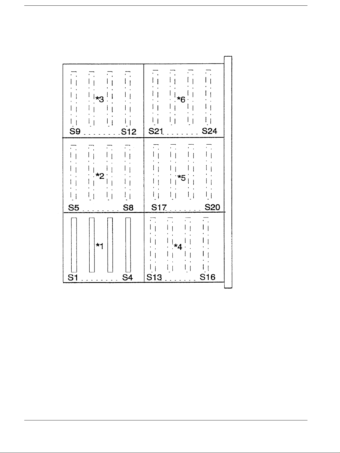
Mass memory board 1
Fig. 1
*1 Section for the first 16 MB (4x4 MB module)
*2 - *6 Sections for further 16 MB increments in order
FLUOROSPOT H/HK Register 3 RX41-020.033.04 Page 6 of 6 Siemens AG
Rev. 04 09.96 TD AX 5 Medical Engineering
Page 11

NOTICE
NOTICE
Display Plus (High Refresh Video) 2
High-speed refresh parts list: 2
ITEM QYT Name
1 1 High refresh key
2 1 Mounting hardware
3 1 Conversion floppy disk
4 1 Option label
5 1 Installation instructions
The FLUOROSPOT H/HK must be Version VD 11 or higher.
• Remove the front panel of the FLUOROSPOT H/HK cabinet.
• Make sure the power to the cabinet is either completel y disconnected or is turned off at
the power distribution system; t hen remove the inside cover.
• Check the version of the video output board.I f the existing video output board is already
a video output board III (board Part No. 50122-0001 or later) continue with the
installation of high refresh key ( page 2-2).
2 - 1
If the existing video output board is a video output board II:
The video output board II and the HCC digital board have to be removed from the IPS
system.
If an analog HCC board is present, this board remains in the IPS system.
If the video output board III is used with a digital hardcopy camera, then the PAL U505
(video output board III) must read 1U505.
If the video output board III is used with an analog hardcopy camera, then the PAL U505
(video output board III) must read 2U505.
Insert the video output board III in the IPS.
Make the following connections (see also page 2-4):
Video Ref. Out to J6 on video output board III
Video Live Out to J5 on video output board III
For digital camera connection, connect the HCC data cable to J8 on video output board
III.
For analog camera connection, connect the HCC video cable to J4 on the analog HCC
board.
Please return the HCC digital board and the video output board II.
Attach the following note:
"Part numb. 12 86 173 XE013 (HCC DIGITAL BOARD)"
"Part numb. 12 86 132 XE013 (VIDEO OUTPUT BOARD live+ ref.)"
"High REFRESH OPTION" return parts
or
"Part numb. 12 86 173 XE013(HCC DIGITAL BOARD)"
"Part numb. 12 86 223 XE013(VIDEO OUTPUT BOARD live only)"
"High REFRESH OPTION" return parts
Siemens AG Register 3 RX41-020.033.04 Page 1 of 6 FLUOROSPOT H/HK
Medical Engineering Rev. 04 09.96 TD AX 5
Page 12

2 - 2Display Plus (High Refresh Video)
Installing the high refresh key 2
1. The Host CPU is located on the right side of t he cabinet. At the bottom edge of the
Host CPU is a row of ”DB” style connectors, including one 25-pin female
connector (J10). If there is no ke y plugged into J10, then do step 2.
2. If the ”Peripheral Angiography Option” key is plugged into J10,then do step 3.2.I f
the small threaded spacers that are used t o secure ”DB” connectors are missing
from J10, install the spacers tha t are supplied with the kit.
If necessary, the connector on the cor ner of the Host CPU (J12) may have to be
removed to get at J10.
Plug the high refresh key into J10 and secur e it to the threaded spacers with the
screws provided.Continue with syst em configuration.
3. Insert the floppy disk (Part No. 30295-0001) supplied with the kit into the
FLUOROSPOT floppy disk drive and power up the system.
When prompted, power down the system, and remove the old key. Change the
label on the new key to read ”30242-0003”, di scard old key. Insert the new key
and power up the system again.
The program then adds the data from the old key to t he new key and the
conversion procedure is complete d. Remove the floppy disk and power down the
system.
System configuration 2
• Remove the CPU board from the IPS and set SW 2 number 5 and 6 to the off (down)
position, and the number 8 to the on (up) position.If an analog HCC board is used in the
IPS system, on the IPS CPU the SW 2 number 5, 6 and 8 has to be set to the of f (down)
position.
• Connect the service PC and enter service mode.
• Go into the system configuration menu and change the High Refresh opt ion to ”YES”.
• Exit configuration menu, save and power down the system.
Calibrating the video output board III 2
• The calibration of the video output board III is only neces sary if this board replaces a
video output board II.
• Place the video output board III on an extender and power up the system.
• Connect the oscilloscope to TP 1500 on the video output board II I.
• Adjust L 1500 on the video output board III (pixel clock phase lock osc.) for a maximum
voltage of about 1.0 V ± 100 mV above ground.
• This completes the pixel clock phase-locked loop adjustment . At this point the LED
D1500 should be solid on (green).
• Power down the system and place video output board III back into t he unit.
• Verify that a display monitor with 75-Ohm termination is conn ected to J10 on the
transition panel and that th e live monitor is connected to J5 on the vi deo output board III.
FLUOROSPOT H/HK Register 3 RX41-020.033.04 Page 2 of 6 Siemens AG
Rev. 04 09.96 TD AX 5 Medical Engineering
Page 13

Display Plus (High Refresh Video) 2 - 3
• Connect the service PC and enter the service mode.Fro m the service PC, select ”Test
Images”, then ”Smooth Gray Scale”, th en select ”Test Image Parameters”. Set the
window upper limit to 381 and the window lower l imit to 380. Press <Enter> to save the
values.
• Connect oscilloscope channel 1 to transition panel TP 5 (video live output) and adjust R
1056 until the signal is 0.7 V ± 50mV black to white (see al so page 2-4).
• Adjust R 1049 pedestal to zero pedestal (+5mV - 0mV).
• Adjust R 1048 sync to 0.3 V ± 50mV.
• Reference output (not present on 50122 - 002 version of video out put board III).
Verify that a display monitor wit h 75-Ohm termination is connected to J8 on tran sition
panel and that the reference monitor i s connected to J6 on the video output board III .
• Connect oscilloscope channel 1 to transition panel TP 2 (video ref. output) and adjust R
1156 until the signal is 0.7 V ± 50mV black to white.
• Adjust R 1149 pedestal to zero pedestal (+5mV - 0mV).
• Adjust R 1148 sync to 0.3 V ± 50mV.
• The difference between Live and Ref black to white signal has to be smaller than 20mV.
Checking the configuration of the SIMOMED-H monitors 2
• Enter the SIMOMED 90H service menu. Check whether the video standard
(62.45 KHz / 100 Hz (61.38 KHz / 120 Hz) is set to the 1: 1 aspect ratio and the standard
changing time is set to 0.
Settings and Configuration with SIMOMED HM Monitors 2
Switching off the exter nal light se ns or 2
Before making the adjustments, switch off the external light sensor as follows:
Switch off the sensor in <<Configuration>><<Powerdown & External light sensor>>.
Siemens AG Register 3 RX41-020.033.04 Page 3 of 6 FLUOROSPOT H/HK
Medical Engineering Rev. 04 09.96 TD AX 5
Page 14

2 - 4Display Plus (High Refresh Video)
Blocking Norms (4:3 screen format) 2
Block norms with the 4:3 screen format in <<Configurati on>><<Block Norms>> as
shown below:
Adjusting Luminous Intensity in 50/60Hz Systems with Display
Plus
The luminous intensity in SIMOMED HM monitors can be adjusted according t o the
norm. Carry out the adjustment as follows for the 100/120Hz Norm:
• Remove jumper JP4 on the FLH Transition Panel and place it on JP5. By doing this, t he
FLH will not switch off in the bypass mode. (Reestablish the jumper position after
making the adjustment!)
• Connect the service cable to the monitor.
• Insert the dynamics test in the beam path and select the Zoom steps so that t he 2L and
5R fields are still completely vi sible (with 40 cm I.I., Zoom 2).
• Use the Mavo monitor to measure the luminous intensity of the 2L and 5 R fi elds in the
LIH image and make a note of the result.
• Switch the Fluorospot to Bypass.
• Select the <<Video Amplifier Adjustment>> <<Bypass>> menu.
2
FLUOROSPOT H/HK Register 3 RX41-020.033.04 Page 4 of 6 Siemens AG
Rev. 04 09.96 TD AX 5 Medical Engineering
Page 15

Display Plus (High Refresh Video) 2 - 5
• Under fluoroscopy (digital and analog), set the fol lowing values by using an alternating
adjustment:
1. Set the same
brightness in the 5R
field as was previously noted in the LIH.
±0.1 cd/m²
2. Set the same
brightness in the 2L
field as was previously noted in the LIH.
±20 cd/m²
• The adjustments of contrast and brightness are not dependent on the video norm and do
not need to be readjusted.
• After completing the adjustment, remove jumper JP5 on t he FLH Transition Panel and
place it back on JP4. By doing this, the FLH will switch off in the bypass mode
(emergency mode).
3. Conclude the
adjustment with
O.K.
Siemens AG Register 3 RX41-020.033.04 Page 5 of 6 FLUOROSPOT H/HK
Medical Engineering Rev. 04 09.96 TD AX 5
Page 16

2 - 6Display Plus (High Refresh Video)
Concluding work 2
• Reattach the inside cover.
• Attach the option label to the inside cover above exi sting option labels.
• Update the product status list for this syste m.
• Reattach the exterior panel.
FLUOROSPOT H/HK Register 3 RX41-020.033.04 Page 6 of 6 Siemens AG
Rev. 04 09.96 TD AX 5 Medical Engineering
Page 17

NOTICE
CAUTION
Image Winchester Upgrade for at least 300 Images 3
This procedure describes installation of the SCSI Image Winchester Option in a
FLUOROSPOT H/HK without a Winchester drive
SCSI Image Winchester Upgrade Parts List 3
ITEM QYT Name
1 1 SCSI Board
2 1 Winchester Drive
3 1 Data Cable
44Screws
5 1 Cable Clamp
6 1 Option Label
7 1 Instructions
FLUOROSPOT 3
3 - 1
Subject: SCSI Image Winchester Upgrade Kit
Part Number: 44 65 928 RV049
Time Required: 4 hours
Run all service diagnostics to verify proper operation of the system before starting the upgrade.
Electrostatically-sensitive parts inside. Do not remove di sk drives
with the power on. Always use proper electrostatic protection
measures when removing disk drives.
Siemens AG Register 3 RX41-020.033.04 Page 1 of 6 FLUOROSPOT H/HK
Medical Engineering Rev. 03 09.96 TD AX 5
Page 18

3 - 2Image Winchester Upgrade for at least 300 Images
Installing the SCSI Control Board
(50070 - 0003 or 50109 - 0003)
• Remove the front panel of the FLUOROSPOT H cabinet then remove the inside cover.
• Make sure the power to the cabinet is either completely disconnect ed or is turned off at
the AC power distribution system in t he cabinet.
• Insert the SCSI control board into the IPS card cage immediately fo llowing the last 16
MB/Mass Memory board. All appropriate boards must be moved one slot to the right so
the SCSI board is installed in the pr oper slot.
Figure shows the configuration for either a 4 or 5 16MB memory board configuration.
3
FLUOROSPOT H/HK Register 3 RX41-020.033.04 Page 2 of 6 Siemens AG
Rev. 03 09.96 TD AX 5 Medical Engineering
Page 19

Image Winchester Upgrade for at least 300 Images 3 - 3
NOTICE
If the Mass Memory board and 16MB boards are both used in the
system then the Mass Memory board must be in the memory slot
furthest to the right. The 16MB boards must be addressed below
the Mass Memory Board.
SCSI Board Switch and Jumper settings
SCSI Board (50070-0003) SCSI EDMA Board (50109-0003)
Number Position Number Position
SW 1 Reset Switch SW 1 1OFF
2OFF
3OFF
4OFF
SW 2 1OFFSW 2 1OFF
2 OFF 2 OFF
3 OFF 3 OFF
4 OFF 4 OFF
5 OFF 5 OFF
6 OFF 6 OFF
7 OFF 7 OFF
8OFF 8ON
SW 3 1OFF
2OFF
3OFF
4OFF
SW 4 1OFFSW 4 1OFF
2 OFF 2 OFF
3 OFF 3 OFF
4 OFF 4 OFF
Jumpers Position Jumpers Position
JP1 IN-2 to 3 JP1 IN-2 to 3
JP2 IN-1 to 2 JP2 IN-2 to 3
JP3 IN-2 to 3 JP3 IN-1 to 2
JP4 IN-1 to 2
JP5 IN-2 to 3
JP6 IN-2 to 3
Siemens AG Register 3 RX41-020.033.04 Page 3 of 6 FLUOROSPOT H/HK
Medical Engineering Rev. 03 09.96 TD AX 5
Page 20

3 - 4Image Winchester Upgrade for at least 300 Images
Installing the Image Winchester drive 3
• Loosen the two screws securing the disk drive mount upright. Rot ate the mount forward
90 degrees to access the rear of t he disk drives.
• Remove the plastic guard covering the mounting hole for th e Winchester drive.
• Slide the Winchester drive through the back of the dis k drive mount and secure it with
four screws.
• Connect the existing power cable that is located behind the dri ve mount to the
Winchester drive.
• Connect the one end of the data cable (65128-0001) to the Winchester drive and t he
other end to J6 on the SCSI board. Secure the cab le by routing it through the white
plastic retainer locat ed on the back wall inside the unit.
• Rotate the drive mount 90 degrees so that is is vertical, and secure the mount with the
two screws.
• Attach the plastic cable clamp to the bottom of the drive mount and i nsert the data cable
throught it.
System Configuration 3
• Connect the Service PC and enter the Service Mode.
• Enter the System Configuration menu and change ”Image Winchester” to YES.
• Exit menu, Save, power down and reboot the system.
• Reenter Service Mode and run IMAGING SYSTEMS TEST.
• ”H. SCSI Board” and ”O. Image Path Tests” to verify proper oper ation of the SCSI Board.
• Test normal FLUOROSPOT H postprocessing operation to verify proper operation of
the Winchester image disk.
• Attach Option label to the inside cover above any exist ing option labels.
• Replace the inside cover and the front panel of the FLUOROSPOT H cabinet.
• Update the Product Status List.
FLUOROSPOT H/HK Register 3 RX41-020.033.04 Page 4 of 6 Siemens AG
Rev. 03 09.96 TD AX 5 Medical Engineering
Page 21

Image Winchester Upgrade for at least 300 Images 3 - 5
Directory Reset Operation 3
• Turn off the system power.
• Place the IPS CPU SW2 position 2 to the off (down) position.
• This will allow the erasure of the current image di sk directory.
• Turn on the system power and allow the system to reboot.
• From the Pat Dir screen enter into the ENTER PATIENT DATA MODE.
• Enter the data for a new patient folder and save the folder by selecting OK.
• This will create a new patient directory on the imag e disk.
• Return to the PAT DIR screen and power down the system.
• Place the IPS CPU SW2 position 2 to the on position.
• Verify that all of the FLUOROSPOT functions are working properly , and the new patient
folder still exists.
• The Winch. capacity is 300 images matrix 1024 or
400 images matrix 884
Siemens AG Register 3 RX41-020.033.04 Page 5 of 6 FLUOROSPOT H/HK
Medical Engineering Rev. 03 09.96 TD AX 5
Page 22

3 - 6Image Winchester Upgrade for at least 300 Images
This page intentionally left blank.
FLUOROSPOT H/HK Register 3 RX41-020.033.04 Page 6 of 6 Siemens AG
Rev. 03 09.96 TD AX 5 Medical Engineering
Page 23

NOTICE
CAUTION
CAUTION
Image Winchester Upgrade for at least 1000 Images 4
This procedure describes the replacement of a 300/400 images
4 - 1
Winchester Drive with a 1GB Winchester Drive.
The FLUOROSPOT H/HK must be Version VD 11 or higher
Because of "Data Privacy Protection" the Winchester Image Disk
has to be deleted completely before removing it from FLUOROSPOT. The removed Winchester Image Disk is property of the
customer
• Remove the front panel of the FLUOROSPOT H/HK cabinet.
• Make sure the power to the cabinet is either completel y disconnected or is turned off at
the power distribution system, t hen remove the inside cover.
• Check the SCSI Winchester board in the IPS system. If the existing SCSI board is
already a ”SCSI EDMA Winchester board” (Part No. 50109-0003 *), proceed as
described under ”Replacement of the Winchest er hard disk drive”.
If the present SCSI board is a SCSI contro l board 1 (Part No.50070-0003 *), re place the
board with a ”SCSI EDMA Winchester board” (Part No.5 0109-0003 *).
*These numbers are board part numbers
4
Replacing the Winchester hard disk drive 4
• Remove two screws holding the disk drive mount uprig ht.
• Tilt the mount forward 90 degrees so that the rear of the disk drive is accessible.
• Disconnect the drive power and SCSI cable from the rear of the hard di sk drive.
Support the disk drive while removing the screws.
• Remove four screws securing the hard disk drive in th e mount, and slide the hard disk
drive out of the front of the mount .
• To install the 1 GB hard disk drive, slide the h ard disk through the front of the disk dr ive
mount and secure it with four screws.
• Connect the drive power and SCSI cable to the ports on the rear of the hard disk drive.
• Tilt the drive mount back in place and secure the mount with t wo screws.
Siemens AG Register 3 RX41-020.033.04 Page 1 of 2 FLUOROSPOT H/HK
Medical Engineering Rev. 05 09.96 TD AX 5
Page 24

4 - 2Image Winchester Upgrade for at least 1000 Images
Switch and Jumper settings SCSI EDMA Board (50109-0003) 4
Number Position Number Position
SW 1 1OFFSW 4 1OFF
2 OFF 2 OFF
3 OFF 3 OFF
4 OFF 4 OFF
SW 2 1OFF Jumper Position
2OFF
3 OFF JP1 IN-2 to 3
4 OFF JP2 IN-2 to 3
5 OFF JP3 IN-1 to 2
6 OFF JP4 IN-1 to 2
7 OFF JP5 IN-2 to 3
8 ON JP5 IN-2 to 3
Resetting Winchester directory 4
- Power down the system.
- Place the IPS CPU SW2 position 2 to the off (down) pos ition. This will allow the
erasure of the current image dis k directory.
- Power up the system and allow the system to r eboot.
- From the PAT DIR screen enter into the ENTER PATIENT DATA MODE.
Enter the data for a new patient folder and save the folder by selecting OK.
This will create a new patient dir ectory on the image disk.
- Return to the PAT DIR screen and power down the system.
- Place the IPS CPU SW2 Position 2 to the ON position.
- Power up the system and allow the system to r eboot.
- Verify that all of the FLUOROSPOT H functions ar e working properly, and the new
patient folder still exist s.
- The Winchester capacity is 1000 images matrix 1024 or 1350 i mages matrix 884.
Concluding work 4
• Reattach the inside cover
• Attach the option label to the inside cover above exi sting option labels.
• Update the product status list for this syste m.
• Reattach the exterior panel.
FLUOROSPOT H/HK Register 3 RX41-020.033.04 Page 2 of 2 Siemens AG
Rev. 05 09.96 TD AX 5 Medical Engineering
Page 25

NOTICE
CAUTION
CAUTION
NOTICE
Digital Optical Disk (DOD) 5
DOD option parts list 5
Item Qty. Name
1 1 DOD interface board
2 1 DOD drive assy.
3 3 Cables
42Screws
5 1 Keycap insert
6 1 Option label
7 1 Instructions
General Remarks 5
The FLUOROSPOT H/HK must be Version VC20/VD10 or higher
before installing this option
5 - 1
• Remove the front panel of the FLUOROSPOT H/HK cabinet.
• Make sure that the power to the cabinet is either compl etely disconnected or is turned off
at the AC power distribution system in the cabinet.
• Remove the inside cover.
Installing the DOD interface board 5
Electrostatically-sensitive parts inside. Do not remove boards
with power ON. Always use proper electrostatic protection measures when removing boards
Do not flex boards while removing them. Pull the boards straight
out of their sockets. Flexing the boards can damage the boards
and the sockets.
• The DOD interface board (board part number 50109-0002) must alway s be installed in
the slot to the right of the Winchest er SCSI board.
Therefore, it is necessary t o move some of the IPS boards.
If no board slot is available in the IPS PC board rack to install the DOD
interface board, then the mass memory upgrade kit (Part No. 44 00
292) must be installed first. This allows the replacement of two 16 MB
memory boards by a single board. See also ”MEMORY EXPANSION”
option.
Siemens AG Register 3 RX41-020.033.04 Page 1 of 4 FLUOROSPOT H/HK
Medical Engineering Rev. 03 09.96 TD AX 5
Page 26

5 - 2 Digital Optical Disk (DOD)
Switch and jumper settings for DOD interface board 5
Switch 1 Pos. 1 OFF
Pos. 2 OFF
Pos. 3 OFF
Pos. 4 OFF
Switch 1 Pos. 1 OFF
Pos. 2 OFF
Pos. 3 OFF
Pos. 4 OFF
Pos. 5 OFF
Pos. 6 ON
Pos. 7 OFF
Pos. 8 OFF
Switch 4 Pos. 1 OFF
Pos. 2 OFF
Pos. 3 ON
Pos. 4 ON
Jumpers JP1 2 to 3
JP2 2 to 3
JP3 2 to 3
JP4 1 to 2
JP5 2 to 3
JP6 1 to 2
• Install DOD interface board in the slot to the right of t he Winchester SCSI board.
Therefore move all the boards on the right side of the Winchester SCSI board one slot to
the right.
• Connect cable (Part No. 65126-0002) to the DOD interface board J5. Rout e the cable
through the box. Using 2 screws, secur e the other end to the top of the metal plate in
front of the transition panel (see Fig.1).
FLUOROSPOT HK:It is not possible to secure the other end. Leave it hanging
inside the box.
FLUOROSPOT H/HK Register 3 RX41-020.033.04 Page 2 of 4 Siemens AG
Rev. 03 09.96 TD AX 5 Medical Engineering
Page 27

Digital Optical Disk (DOD) 5 - 3
Installing the DOD assembly 5
• Connect cable (Part No. 65250-0001) from the back of the DOD assembly to t he bottom
of the metal plate on the transiti on panel assembly (see Fig.1).
• Connect the power cable from the back of the DOD assembly to TB4 of the AC power
distribution system of the FLUOROSPOT H/HK.
TB4-1 Ground (green/yellow)
2 Line (brown)
3 Neut ral (blue)
Miscellaneous 5
• Connect the service PC and enter the service mode.
• Go into the system configuration menu and change the DOD option to YES.
• Exit menu, save and reboot the system.
• Confirm that ”DOD DIR” appears on the patient directory.
• Add DOD keycap to keyboard above the ”hardcopy single image” key.
• Enter the service mode and run DOD-related imaging system tes ts and interface tests.
• Attach the option label to the inside cover abov e existing option labels.
• Reattach the inside cover and front panel of the FLUOROSPOT H cabinet.
Siemens AG Register 3 RX41-020.033.04 Page 3 of 4 FLUOROSPOT H/HK
Medical Engineering Rev. 03 09.96 TD AX 5
Page 28

5 - 4 Digital Optical Disk (DOD)
FLUOROSPOT H/HK Register 3 RX41-020.033.04 Page 4 of 4 Siemens AG
Rev. 03 09.96 TD AX 5 Medical Engineering
Page 29

Peripheral Angiography 6
Peripheral Angiography parts list 6
ITEM QYT Name
1 1 Pery key
2 1 Mounting hardware
3 1 Conversion floppy disk
4 1 Option lable
5 1 Installation Instructions
• Remove the front panel of the FLUOROSPOT H cabinet then remove the inside cov er.
• Make sure the power to the cabinet is either completel y disconnected or is turned off at
the AC Power Distribution System in the cabinet .
Installing the Peripheral Angiography key 6
1. The Host CPU is located on the right side of t he cabinet. At the bottom edge of the
Host CPU is a row of ”DB” style connectors, incl uding one 25-pin female
connector (J10). If there i s no key plugged into J10, then do ste p 2. If the ”High
Refresh Option” key is plugged int o J10, then do step 3.
6 - 1
2. If the small threaded spacers that ar e used to secure ”DB” connectors are missing
from J10, install the spacers that are supplied with the kit.
If necessary, the connector on t he corner of the Host CPU (J12) may have to be
removed to get at J10.
Plug the Peripheral Angiography Opt ion key into J10 and secure it to the threade d
spacers with the screws provided.
Continue with system configuration FLUOROSPOT H.
3. Insert the floppy disk (Part No. 30295-0001) supplied with the kit int o the
FLUOROSPOT floppy disk drive and power up the system.
When prompted, power down the system, and remove the old key. Change the
label on the new key to read ”30242-0003” , discard old key. Insert the new key
and power up the system again.
The program then adds the data from the old key to t he new key and the
conversion procedure is completed .Remove the floppy disk and power down the
system.
System Configuration FLUOROSPOT H 6
• Connect the Service PC and enter the service mode
• Go into rhe system configuration menu and change the Peripheral Angiography Option
to ”YES”.
• Set the number of Peri Positions to 6 (set for SIREGRAPH D340 ).
• Exit menu, save and power down the system.
Siemens AG Register 3 RX41-020.033.04 Page 1 of 4 FLUOROSPOT H/HK
Medical Engineering Rev. 05 09.96 TD AX 5
Page 30

6 - 2Peripheral Angiography
Table-specific changes 6
• The necessary hard and software changes for the SIREGRAPH D340 are discribed in:
- MORX Modification Instructions No. 11/ 92 Firmware Info 11
- MORX Modification Instructions No. 23/ 93 Firmware Info 15
• Configure "Peripheral Stepping" in the POLYSTAR "Adjustment" menu ( System
Configuration)
Generator-specific changes 6
• POLYDOROS S
- The POLYDOROS S must have the software version VG2 (see also Speed Info 106/
91 ”POLYDOROS 50/80S” R67-010.117.01.05.01)
- In the generator configuration (see al so System configuration, staring f rom VG1 R67-
010.034.07...) Module J40 set t he parameter ”PERI” to YES and the Exposure Point
(EP) reduction as follow:
Step 1 1 EP
Step 2 1 EP
Step 3 3 EP
Step 4 4 EP
Step 5 1 EP
• POLYDOROS SX 50/80
- POLYDOROS SX software version <VC00B, in the generator configurat ion Module
J40 set the parameter ”PERI” to YES and the Exposure Poi nt (EP) reduction as above
mentioned.
- POLYDOROS SX software version ?VC00B, in the mask DR-settings selec t
”Peripheral Angiography” and set the Exposure Point (EP) reduction as above
mentioned.
- See also Startup Instruction, Syst em configuration starting wi th VC00B
RX63-050.034 (depending on listed softwar e version)
• POLYDOROS SX 65/80 (XCS)
- No settings are necessary for th e generator. Exposure point reducti on is not variable
with this generator.
Configure Peri Stepping in the XCS Site Struct ure menue for the R/F table.
FLUOROSPOT H/HK Register 3 RX41-020.033.04 Page 2 of 4 Siemens AG
Rev. 05 09.96 TD AX 5 Medical Engineering
Page 31

Peripheral Angiography 6 - 3
Test 6
• Select PERI on the SIREGRAPH D340 remote contol console
• At the FLUOROSPOT operator console enter the Organ Program menu and note that
PERI organ programs are now available
• Select a PERI organ program and try the system to validate operat ion.
Conclusion 6
• Turn system power of the FLUOROSPOT off and replace the IPS cover.
• Install the option lable on the IPS cover belo w other option lables which are there.
• Update the poduct status list for this system.
• Replace the exterior cover
Siemens AG Register 3 RX41-020.033.04 Page 3 of 4 FLUOROSPOT H/HK
Medical Engineering Rev. 05 09.96 TD AX 5
Page 32

6 - 4Peripheral Angiography
This page intentionally left blank.
FLUOROSPOT H/HK Register 3 RX41-020.033.04 Page 4 of 4 Siemens AG
Rev. 05 09.96 TD AX 5 Medical Engineering
Page 33

Changes to Previous Version 7
All Pages New layout
Chapter 0
Page 1
Page 2
Page 3
Page 4
Chapter 1
Page 1
Page 2
Chapter 2
Page 4 Paragraph. "Adjustment and configuration for SIMOMED HM monitors"
Chapter 3
Page 5 Last point added.
Print Number, date and Revision level updated.
Revision level table new.
Table of Contents updated.
Paragraphs "Documents required" and "Measuring ins tr uments and
devices required" in Chap.1 moved and contents change d.
1st paragraph of "Note" eliminated.
Under 4. "VD11 only" eliminated and "Note" added.
new.
7 - 1
Chapter 4
Page 4 The first 3 points in paragraph "Resetting...." eliminated and last line
added.
Chapter 6
Page 1
Page
Chapter 7 Updated.
"Note" eliminated.
Under "Table specific....." new point "Configure..." added.
Paragraph "POLYDOROS SX65/80 (XCS)" added.
TD AX 5/Blum
TD AX 1/Biedermann,Tropia
Siemens AG Register 3 RX41-020.033.04 Page 1 of 2 FLUOROSPOT H/HK
Medical Engineering Rev. 02 09.96 TD AX 5
Page 34

7 - 2 Changes to Previous Version
This page intentionally left blank.
FLUOROSPOT H/HK Register 3 RX41-020.033.04 Page 2 of 2 Siemens AG
Rev. 02 09.96 TD AX 5 Medical Engineering
 Loading...