

Page 1

FLUOROSPOT H/HK
Installation Instructions
AX
Non-SIEMENS Laser Camera
Digitally Connected
Valid for FL-H/HK
© Siemens AG 1995
The reproduction, transmission or
use of this document or its contents
is not permitted without express
written authority. Offenders will be
liable for damages. All rights,
including rights created by patent
grant or registration of a utility
model _or_ design,_are_ reserved.
Register 3 English
Print No.: RX41-020.031.01.10.02 Doc. Gen. Date: 12.96
Replaces: RX41-020.031.01.09.02
Page 2

0 - 2Revision
Chapter Page Revision
0all09
1all09
2all09
3all06
4all01
0all10
1all10
2all10
3all07
4all02
5all01
FLUOROSPOT H/HK Register 3 RX41-020.031.01 Page 2 of 4 Siemens AG
Rev. 10 12.96 TD AX 5 Medical Engineering
Page 3

Contents 0 - 3
Page
1 _______Prerequisites __________________________________________________ 1 -1
Required Documents . . . . . . . . . . . . . . . . . . . . . . . . . . . . . . . . . . 1 -1
Required Test Equipment and Devices . . . . . . . . . . . . . . . . . . . . . . . . . 1 -1
General . . . . . . . . . . . . . . . . . . . . . . . . . . . . . . . . . . . . . . . . . 1 -1
Parts of optical Camera Link (OCL) for La ser Cam e ras. . . . . . . . . . . . . . . . . 1 -2
Survey of OCL Connection (Block Diagram) . . . . . . . . . . . . . . . . . . . . . . 1 -2
Units without OCL . . . . . . . . . . . . . . . . . . . . . . . . . . . . . . . . . . . . 1 -3
Check of the Opto Modules OZDV 241/246* (Hirschmann). . . . . . . . . . . . . . . 1 -4
FLUOROSPOT H/HK System Configuration . . . . . . . . . . . . . . . . . . . . . . 1 -4
2 _______Connection of the Camera _______________________________________ 2 -1
3M PLUS (M952 with HCI) . . . . . . . . . . . . . . . . . . . . . . . . . . . . . . . 2 -1
Hardware Requirements. . . . . . . . . . . . . . . . . . . . . . . . . . . . . . . 2 -1
Configuration . . . . . . . . . . . . . . . . . . . . . . . . . . . . . . . . . . . . 2 -1
Jumper Setting HCI-BOX . . . . . . . . . . . . . . . . . . . . . . . . . . . . . . 2 -2
Hardware Requirements. . . . . . . . . . . . . . . . . . . . . . . . . . . . . . . 2 -3
3M (M959 XL with HCI) . . . . . . . . . . . . . . . . . . . . . . . . . . . . . . . . . 2 -4
Jumper Setting HCI-BOX . . . . . . . . . . . . . . . . . . . . . . . . . . . . . . 2 -5
3M HQ (M969 with SHPT). . . . . . . . . . . . . . . . . . . . . . . . . . . . . . . . 2 -6
AGFA MCL with AGFA-MIN . . . . . . . . . . . . . . . . . . . . . . . . . . . . . . . 2 -8
Hardware Requirements. . . . . . . . . . . . . . . . . . . . . . . . . . . . . . . 2 -8
Configuration . . . . . . . . . . . . . . . . . . . . . . . . . . . . . . . . . . . . 2 -8
AGF A MG 3000 + LR 3300.. . . . . . . . . . . . . . . . . . . . . . . . . . . . . . 2 -10
KODAK XLP / 1120 / 2180 . . . . . . . . . . . . . . . . . . . . . . . . . . . . . . 2 -12
DU PONT LINX-NET . . . . . . . . . . . . . . . . . . . . . . . . . . . . . . . . . 2 -14
Hardware Requirements. . . . . . . . . . . . . . . . . . . . . . . . . . . . . . 2 -14
Configuration . . . . . . . . . . . . . . . . . . . . . . . . . . . . . . . . . . . 2 -14
KONICA LI10A . . . . . . . . . . . . . . . . . . . . . . . . . . . . . . . . . . . . 2 -16
Configuration . . . . . . . . . . . . . . . . . . . . . . . . . . . . . . . . . . . 2 -17
FUJI FL-IM 3543 . . . . . . . . . . . . . . . . . . . . . . . . . . . . . . . . . . . 2 -18
Hardware Requirements. . . . . . . . . . . . . . . . . . . . . . . . . . . . . . 2 -18
Configuration . . . . . . . . . . . . . . . . . . . . . . . . . . . . . . . . . . . 2 -18
3 _______Service _______________________________________________________ 3 -1
Hardcopy Driver Modification . . . . . . . . . . . . . . . . . . . . . . . . . . . . . . 3 -1
Service Tools for Tracing the SPCI/SPDI Interface . . . . . . . . . . . . . . . . . . . 3 -2
1. Tester for the Control Interface . . . . . . . . . . . . . . . . . . . . . . . . . . 3 -2
2. Linktest Board. . . . . . . . . . . . . . . . . . . . . . . . . . . . . . . . . . . 3 -3
Check of the OCL . . . . . . . . . . . . . . . . . . . . . . . . . . . . . . . . . . 3 -6
Camera Interface Test System . . . . . . . . . . . . . . . . . . . . . . . . . . . 3 -6
Hardcopy Error Messages. . . . . . . . . . . . . . . . . . . . . . . . . . . . . . . . 3 -8
4 _______Abbreviations__________________________________________________ 4 -1
5 _______Changes to Previous Version_____________________________________ 5 -1
Siemens AG Register 3 RX41-020.031.01 Page 3 of 4 FLUOROSPOT H/HK
Medical Engineering Rev. 10 12.96 TD AX 5
Page 4

0 - 4 Contents
Page
This page intentionally left blank.
FLUOROSPOT H/HK Register 3 RX41-020.031.01 Page 4 of 4 Siemens AG
Rev. 10 12.96 TD AX 5 Medical Engineering
Page 5

Prerequisites 1
Required Documents 1
• Service Manual FLUOROSPOT H 89999-0031
Required Test Equipment and Devices 1
• Service PC according specificat ions in the ARTD part 1 3.1.0
• SST 320 terminal emulation, 97 04 586 Y4364
General Remarks 1
The startup of the camera is performed by the technical service of the respective camera
manufacturer.
Survey when an OCL is necessary
1 - 1
Camera Distance between
FL-H and HCC
3M XL(959)
3M HQ(969)
AGFA MCL /
MIN / MG 3000
with MFRI Board
Rev. A-D
AGFA MCL /
MIN / MG 3000
with MFRI Board
Rev. E and >
All other cameras,
Multiple Modality
All other cameras,
Single Modality
___________ ___________
< = 30m
< = 30 m
> 30 m
> 30 m
< = 60m
< = 60 m
> 60 m
> 60 m
< = 60m
< = 60 m
> 60 m
> 60 m
< = 60m
< = 60 m
> 60 m
> 60 m
FL-H / HK and
HCC at the same
power distribution
YES
NO
YES
NO
YES
NO
YES
NO
n.a.
n.a
n.a
n.a
YES
NO
YES
NO
OCL
necessary
NO
NO
YES
YES
YES
NO
NO
YES
YES
YES
YES
YES
YES
NO
YES
YES
YES
Siemens AG Register 3 RX41-020.031.01 Page 1 of 6 FLUOROSPOT H/HK
Medical Engineering Rev. 10 12.96 TD AX 5
Page 6
1 - 2Prerequisites
Parts of optical camera link (OCL) for laser cameras 1
Kit for the optical camera link, Part No:11 76 671 X2176
Includes:
Transmitter (Host Module) No: 46 83 629 B4001
Date cable to FL-H No: 46 84 270 B5620
Control cable to FL-H No: 46 83 561 B1940
Mains cable No: 11 69 197 X2115
Receiver (Camera Module) No: 46 83 637 B4002
Data cable to laser camera No: 46 83 579 B1940
Control cable to laser camera No: 46 83 561 B1940
Power cable (3 m) No: 46 83 595 B1948
Order separately: :
Duplex optical fiber (30 m) No: 46 89 469 B4003 or
Duplex optical fiber (100 m No: 46 90 756 B4003
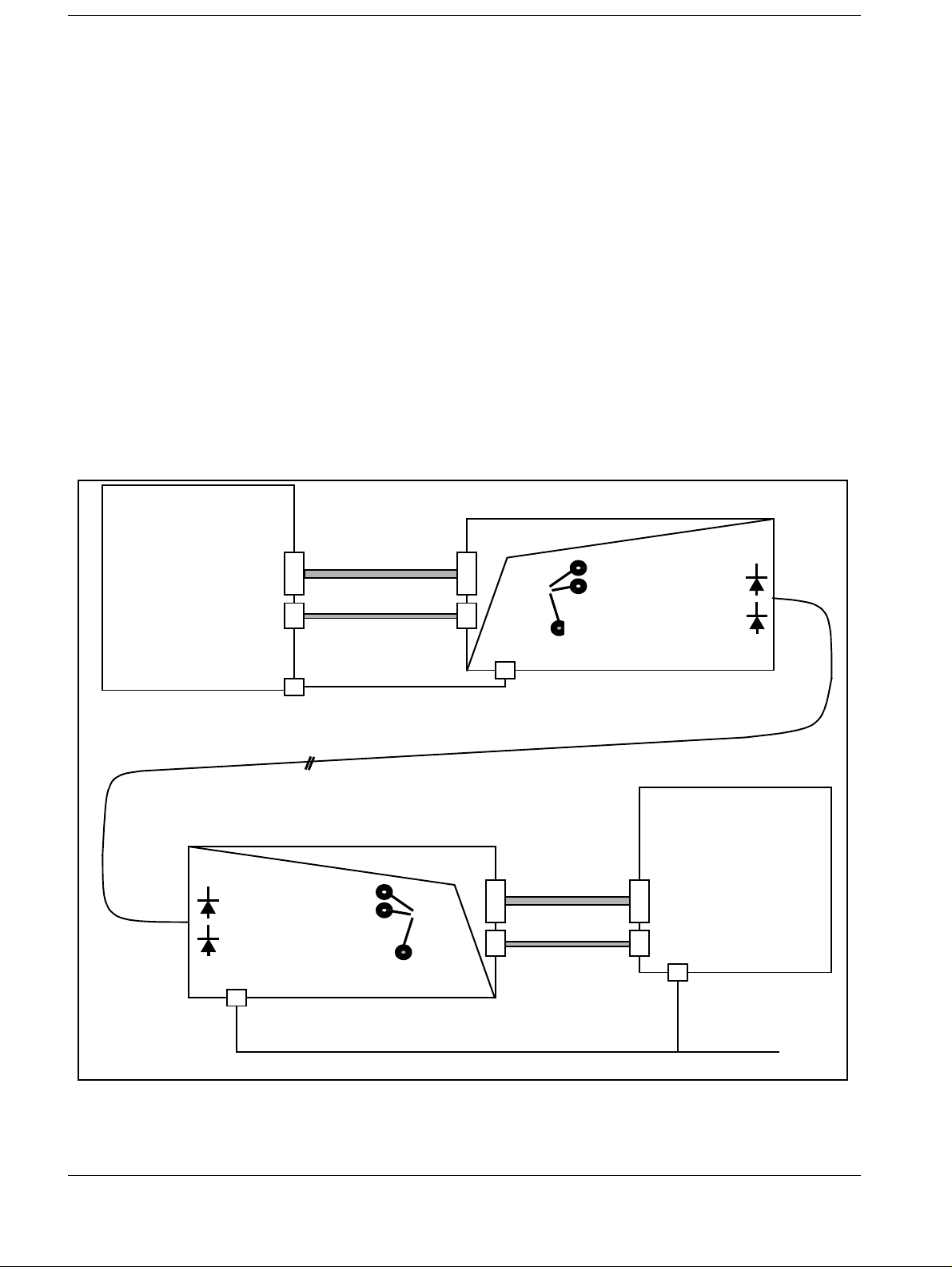
Survey of OCL connection (Block Diagram) 1
Transmitter
FL-H
J26
J29
46 84 270
B5620
46 83 561
11 69 197 X2115
46 83 629B4001
Host module
Camera Request
Host Clock
Leds
green:Power supply ok
red blinking:
Power supply failure
Fig. 1
Duplex optical fiber
46 90 756 B4003 (100 m)
OPT FIBER
230 VAC power
46 89 469 B4003 (30 m)
Receiver
46 83 637 B4002
Camera module
Camera Request
Host Clock
green:Power supply ok
red blinking: Power supply failure
230 VAC power
46 83 595 B1948 (3 m)
Leds
Digital laser camera
46 83 579 B1940
Data cable
Control cable
46 83 561 B1940
FLUOROSPOT H/HK Register 3 RX41-020.031.01 Page 2 of 6 Siemens AG
Rev. 10 12.96 TD AX 5 Medical Engineering
Page 7
Prerequisites 1 - 3
NOTICE
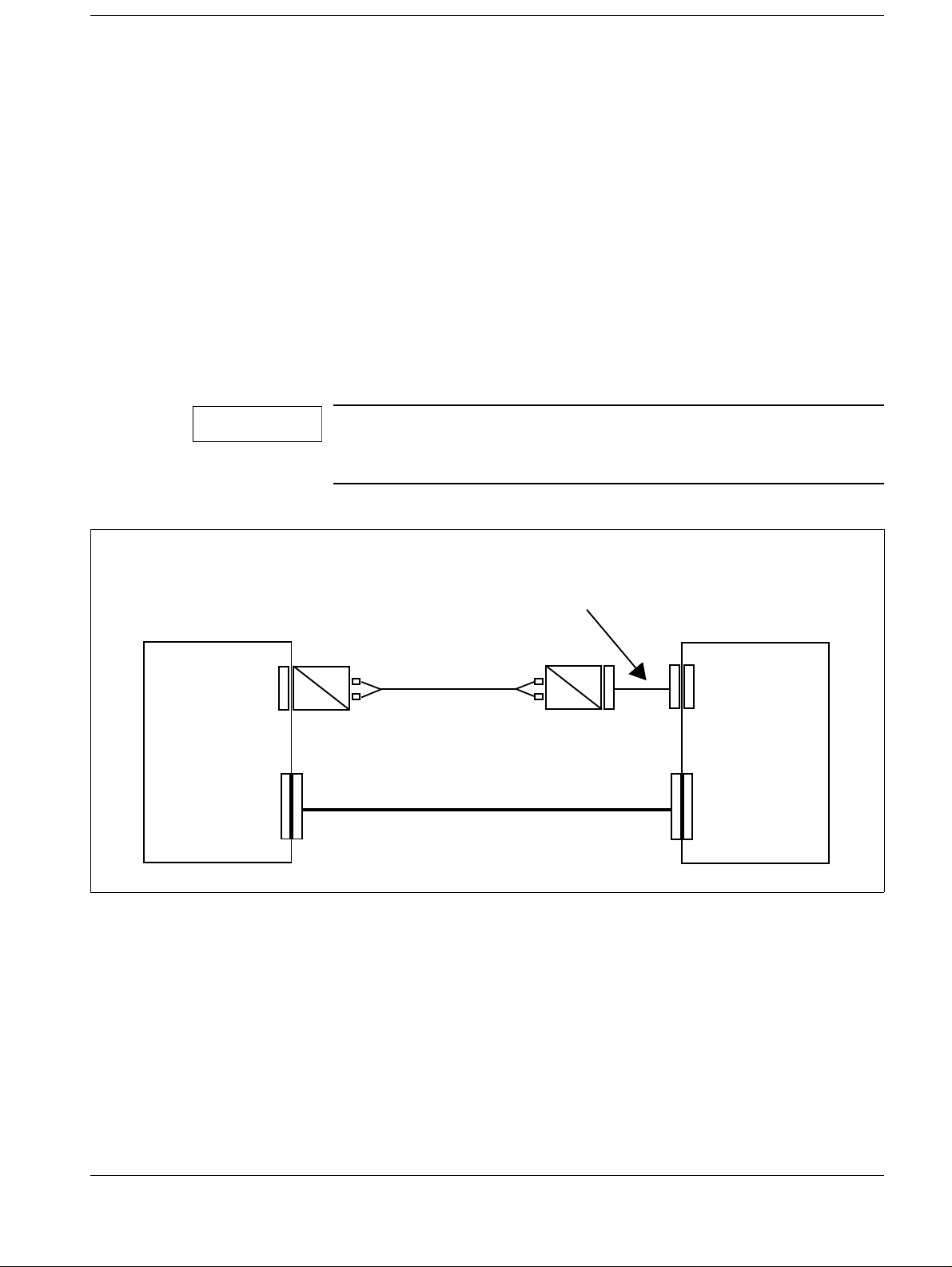
Units without OCL 1
Cable set, 26 m 26 m No: 44 90 421 RH041
Includes:
Data cable 26 m No: 11 63 307 X1755
Fiber optic cable (FOC) 30 m No: 77 60 598 B4003
2 Opto modules for 30 m FOC) 2 x No: 77 60 606 B4002
Cable set, 60m 60 m No: 44 90 439 RH041
Includes:
Data cable 60 m No: 16 00 100 X1755
Fiber optic cable (FOC) 60 m No: 46 95 821 B 4003
2 Opto modules for 60 m FOC 2 x No: 46 71 228 B4002
Adapter cable for 60 m FOC No: 11 76 978 X2115
Note: When opto module for 60 m FOC is used, there is a danger
of kinking the FOC. To avoid kinking, use an adapter cable
between J 29 (FLUOROSPOT) and the opto module.
Fig. 2
Connection HCC
Adapter cable only used
by opto decoupler for 60m foc
*
O
E
Fiber Optical Cable 30/60 m
Image Data Cable 26/60 m
O
FLUOROSPOT H /HK
Transition Panel
*
E
HCC Control
J29
HCC IMAGE
J26
Siemens AG Register 3 RX41-020.031.01 Page 3 of 6 FLUOROSPOT H/HK
Medical Engineering Rev. 10 12.96 TD AX 5
Page 8
1 - 4Prerequisites
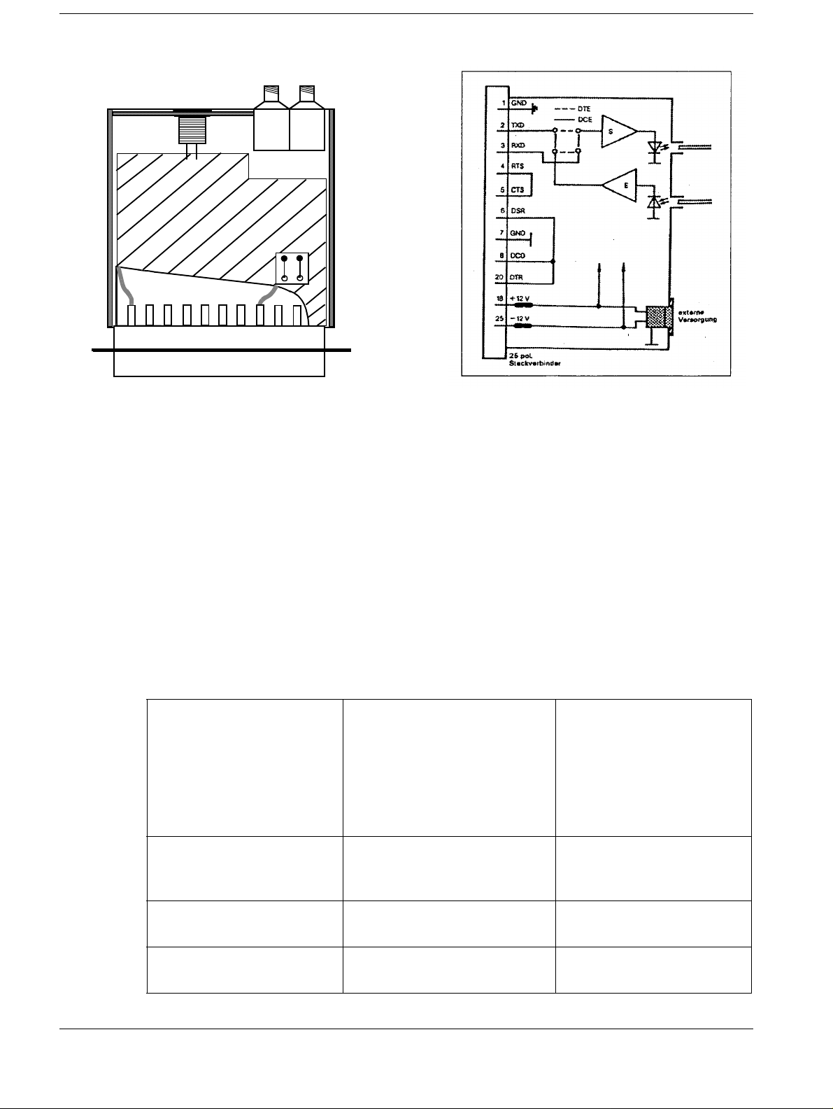
Pin 25 Pin 18
Fig. 3 Fig. 4
Check of the OZDV 241/246* Opto Modules (Hirschmann) 1
• Open both Opto Modules and check whether the jumpers for TxD and RxD are in th e
correct position (see Fig. 1).
• Check whether the solder connections for the internal voltage supply (ñ12 V) have been
made (see Fig. 2) and close the Opto Modules.
Safety note
Observe the safety notes in Reg. 2 of the FLUOROSPOT H service manual.
FLUOROSPOT H/HK System Configuration 1
(see also Service Manual FLUOROSPOT H VC21 / VD10 or VC22 / VD11 Chapter 3
”Software Configuration”).
HCC type DIGICAM/LINXNET2; 3M
959/969-SHPT-2;AGFA-MCL3; AGFA-MCL-4 ;KODAK-XLP4; KODAK-2180/1120-2;KONICA-LI10A-2; FUJI-3543P2Further camera driver see
2-26
e. g. DIGICAM /LINXNET 2
Default HCC multiple format 1:1; 2:1; 4:1; 6:1; 8:1; 9:1;
12:1; 15:1; 16:1; 20:1; and
mixed formats *
Default HCC multiple film
size
Default HCC single format same selection as multiple for-
FLUOROSPOT H/HK Register 3 RX41-020.031.01 Page 4 of 6 Siemens AG
Rev. 10 12.96 TD AX 5 Medical Engineering
14 x 17; 1 1 x 14; 8 x 10; 14 x
14 *
mat possible
e.g. 4:1
e.g. 14 x 17
e.g. 2 + 8:1
Page 9

Prerequisites 1 - 5
Default HCC single film size same selection as multiple
size possible
HCC interpolation mode
(multiple)
HCC interpolation mode
(single)
HCC film density (optical
density x100)
HCC LUTs 1
HCC black level used for analog cameras only 0
HCC white to black level
(mV)
*depending on camera used
Configuration of format default settings
It is possible to configure one of the camera supported formats as default in both menu
points HCC multiple format and HCC single format.
used for analog cameras only 700
e.g. 11 x 14
SMOOTH
SMOOTH
300
Hardcopy Camera HCC Firmware
(minimum version)
3M PLUS (M952)
via HCI
3M XL (M959)
via HCI,
3M HQ (M969)
via SHPTV1.2
AGFA MCL
MIN
Mixed formats
AGFA MG 3000 + LR 3300 MeGa1P10
Version 2.3
Version 3.2 (HCI
Special LUT firmware: 321A
Version 2.0
Version 3.2 (HCI)
Special LUT firmware:322AO
SMCL 01416
SUM 02017
AGFA Camera patch required
OEMMG 010
FL-H Camera Driver
3M 952-HCI-2
3M 959/969-HCI-2
3M 959/969-SHPT-2
AGFA-MCL-3
AGFA-MCL-4
AGFA-MCL-3 /
AGFA-MCL-4
Siemens AG Register 3 RX41-020.031.01 Page 5 of 6 FLUOROSPOT H/HK
Medical Engineering Rev. 10 12.96 TD AX 5
Page 10

1 - 6Prerequisites
Hardcopy Camera HCC Firmware
(minimum version)
KODAK XLP CPDI 2.2 KODAK-XLP-3
KODAK 1120 CPDI 2.2 KODAK-XLP-3
KODAK XLP CPDI 2.3 KODAK-XLP-4
KODAK 1120 CPDI 2.3
CPDI > 2.3 (planned for future)
KODAK 2180 CPDI 2.3
CPDI > 2.3 (planned for future)
DIGICAM
Du Pont LINXNET,
LP400 with LINXNET only
KONICA LI10A Version 2.0 FLH Protocol KONICA-LI10-A-2
FUJI FL-IM 3543 (portrait)
884 x 884 Matrix
1024 x 1024 Matrix
Version 22
Rev. 2.0
14Y5749001D05, AE01PR 003
14Y5749001D05, AE01PR 002
FL-H Camera Driver
KODAK 2180/1120-2
KODAK 2180/1120-3
KODAK 2180/1120-2
KODAK 2180/1120-3
DIGICAM/LINXNET2
FUJI-3543-P2
FUJI FL-IM 3543 (landscape)
884 x 884 Matrix
1024 x 1024 Matrix
Other cameras Generic Digital 2
14Y5749001D05, AE01PR 003
14Y5749001D05, AE01PR 002
FUJI-3543-L2
FLUOROSPOT H/HK Register 3 RX41-020.031.01 Page 6 of 6 Siemens AG
Rev. 10 12.96 TD AX 5 Medical Engineering
Page 11
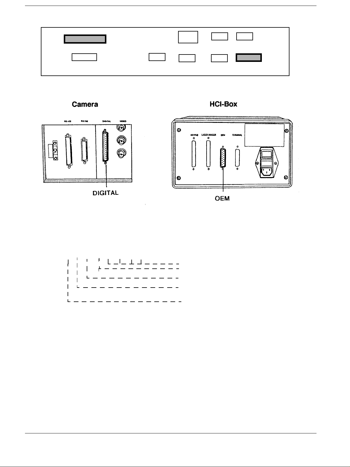
Connection of the camera 2
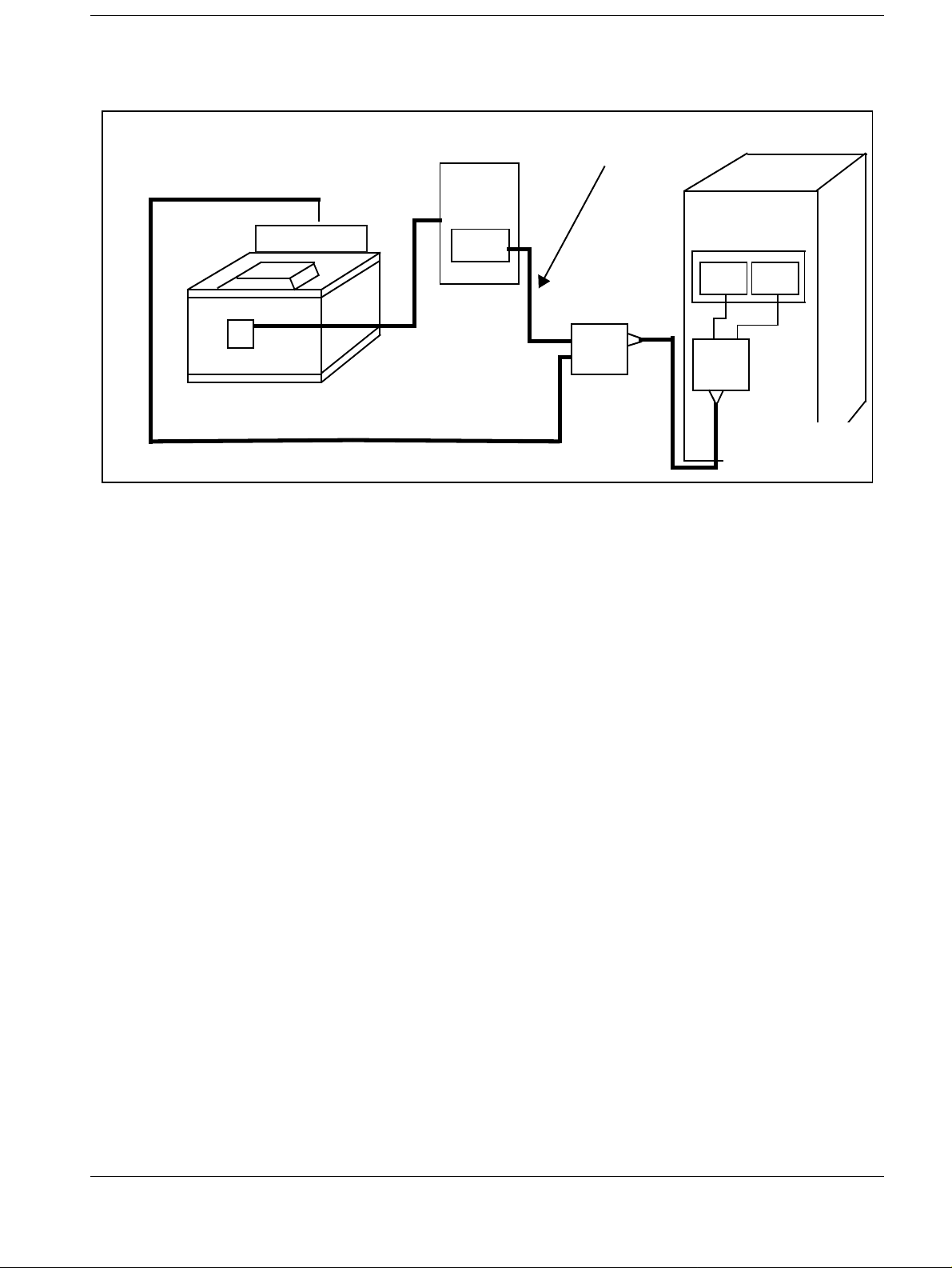
3M PLUS (M952 with HCI) 2
Example with OCL
FLUOROSPOT H/HK
HOST- CONTR.
3-M laser camera
DIGITAL
HCI
Box
OEM
HC
TRANSITION
PANEL
2 - 1
J26
*
Duplex Optical
Fiber Cable *
*
*
IMAGE- DATA *
Fig. 1
*Parts of the Optical Camera Link
*
CAM.
MOD.
J29
*
Host
MOD.
Hardware requirements 2
• HCC digital board or VIDEO OUT III board in the FLUOROSPOT is neces sary
• Whether an OCL is necessary see page 1-1
Configuration 2
In the FLUOROSPOT SYSTEM CONFIGURATION (see page 1-4), set the menu point
”HCC type” to ”3M 952-HCI-2”.
Supported formats see page 2-20
The selectable formats are also depending from the memory-expansion of the 3M-PLUS
camera
Siemens AG Register 3 RX41-020.031.01 Page 1 of 22 FLUOROSPOT H/HK
Medical Engineering Rev. 10 12.96 TD AX 5
Page 12
2 - 2 Connection of the camera
FLUOROSPOT H/HK TRANSITION PANEL..
HCC IMAGE
Fig. 2
.
J26
J26
J25
SK 111
J32
AUX 2
J22 J23 J24
AC DIST KEYBOARD REMOTE
J27 J28
SERVICE
AUX 1
J29
HCC CTL
Fig. 3
Jumper Setting HCI-BOX 2
The DIP switch on the CPU-Board (HCI-Box) has to be set to the proper position
DIP switch on HCI-CPU Board
1 2 3 4 5 6 7 8
not used
OFF
ON: FLUOROSPOT selected
OFF: others
ON: LASER IMAGER (M959)
OFF: LASER IMAGER (M952)
ON: MMU Operation
OFF:stand-alone
Fig. 4
If the CPU is correctly set, the HCI must display ”SET UP FOR FLUOROSPOT H” for
some seconds after power up.
Other notes
If contrast curve 12 is selected in the 3M-PLUS camera, the monitor image impression
largely coincides with the film.
FLUOROSPOT H/HK Register 3 RX41-020.031.01 Page 2 of 22 Siemens AG
Rev. 10 12.96 TD AX 5 Medical Engineering
Page 13
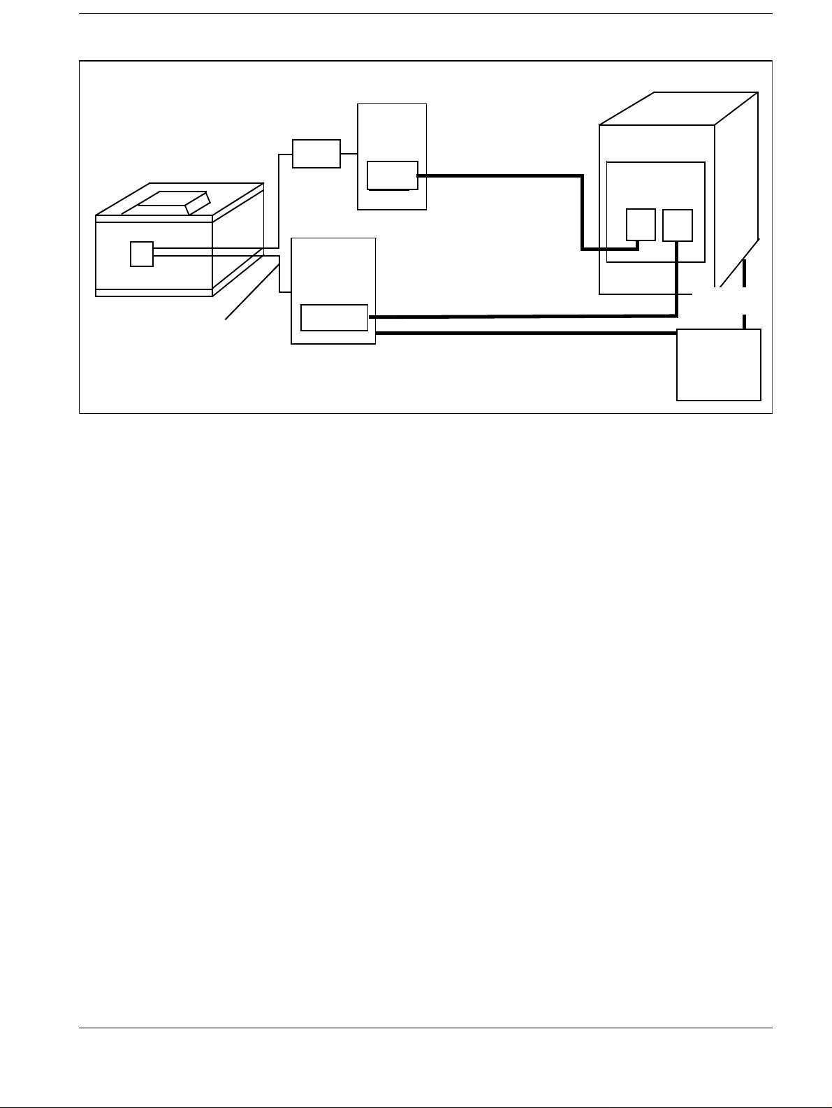
Connection of the camera 2 - 3
FLUOROSPOT H/HK
3-M laser camera
3M fiber optic cable
Fig. 5
*) connect to the same power distribution panel
KEIB = KEYPAD-EXTERNAL-INTERFACE-BOX
HCI = HOST-CONTROL-INTERFACE
DEIB = DATA-EXTERNAL-INTERFACE-BOX
KEIB
DEIB
PORT 0
HCI
Box
OEM
HC
HOST-CONTR.
fiber-optic cable
IMAGE-DATA CABLE
power (DEIB)
TRANSITIONPANEL
*)
J29
J26
power*)
power
distrib.
Hardware requirements 2
• HCC digital board or VIDEO OUT III Board in the FLUOROSPOT is necessary
• OCL (Optical Camera Link) is not necessa ry.
• Cable sets 30/60m: see page 1-2
Siemens AG Register 3 RX41-020.031.01 Page 3 of 22 FLUOROSPOT H/HK
Medical Engineering Rev. 10 12.96 TD AX 5
Page 14
2 - 4 Connection of the camera
3M (M959 XL with HCI) 2
Configuration
In the FLUOROSPOT H SYSTEM CONFIGURATION (see page 1- 4), set the menu point
”HCC type” to ”3M-959/969-HCI-2”.
Supported formats see page 2-20
The selectable formats are also depending from the memory-expansi on of the 3M
camera.
FLUOROSPOT H/HK TRANSITION PANEL.
HCC IMAGE
Fig. 6
J26
J26
J25
SK 111
J32
AUX 2
J22 J23 J24
AC DIST KEYBOARD REMOTE
J27 J28
SERVICE
AUX 1
J29
HCC CTL
FLUOROSPOT H/HK Register 3 RX41-020.031.01 Page 4 of 22 Siemens AG
Rev. 10 12.96 TD AX 5 Medical Engineering
Page 15
Connection of the camera 2 - 5
.
Fig. 7
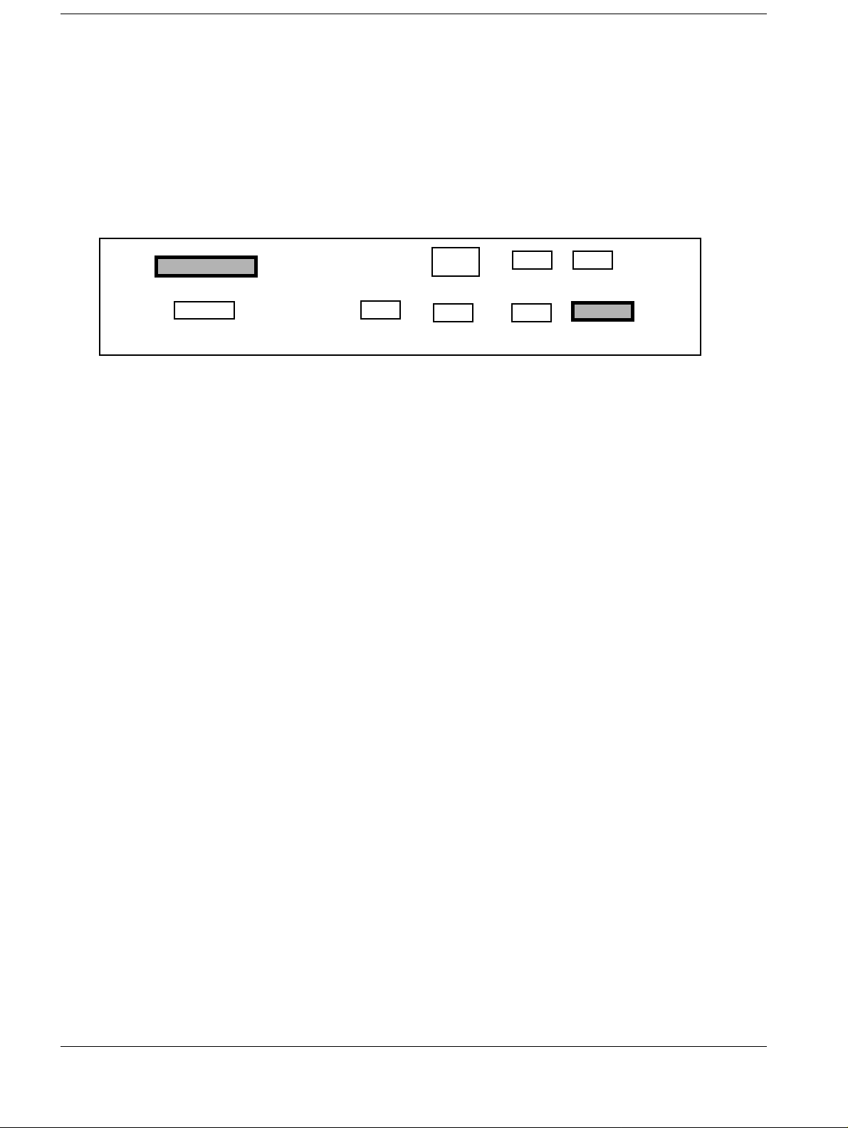
Jumper Setting HCI-BOX 2
The DIP switch on the CPU-Board (HCI-Box) has to be set to the proper position
DIP switch on HCI-CPU Board
1 2 3 4 5 6 7 8
not used
OFF
ON: FLUOROSPOT selected
OFF: others
ON: LASER IMAGER (M959)
OFF: LASER IMAGER (M952)
ON: MMU Operation
OFF:standalone
Fig. 8
If the CPU is correctly set , the HCI must display ”SET UP FOR FLUOROSPOT H” for
some seconds after power up
..
Fig. 9
Other notes
If contrast curve 9 is selected i n the 3M-XL camera, t he monitor image impressi on largel y
coincides w ith th e film
Siemens AG Register 3 RX41-020.031.01 Page 5 of 22 FLUOROSPOT H/HK
Medical Engineering Rev. 10 12.96 TD AX 5
Page 16

2 - 6 Connection of the camera
NOTICE
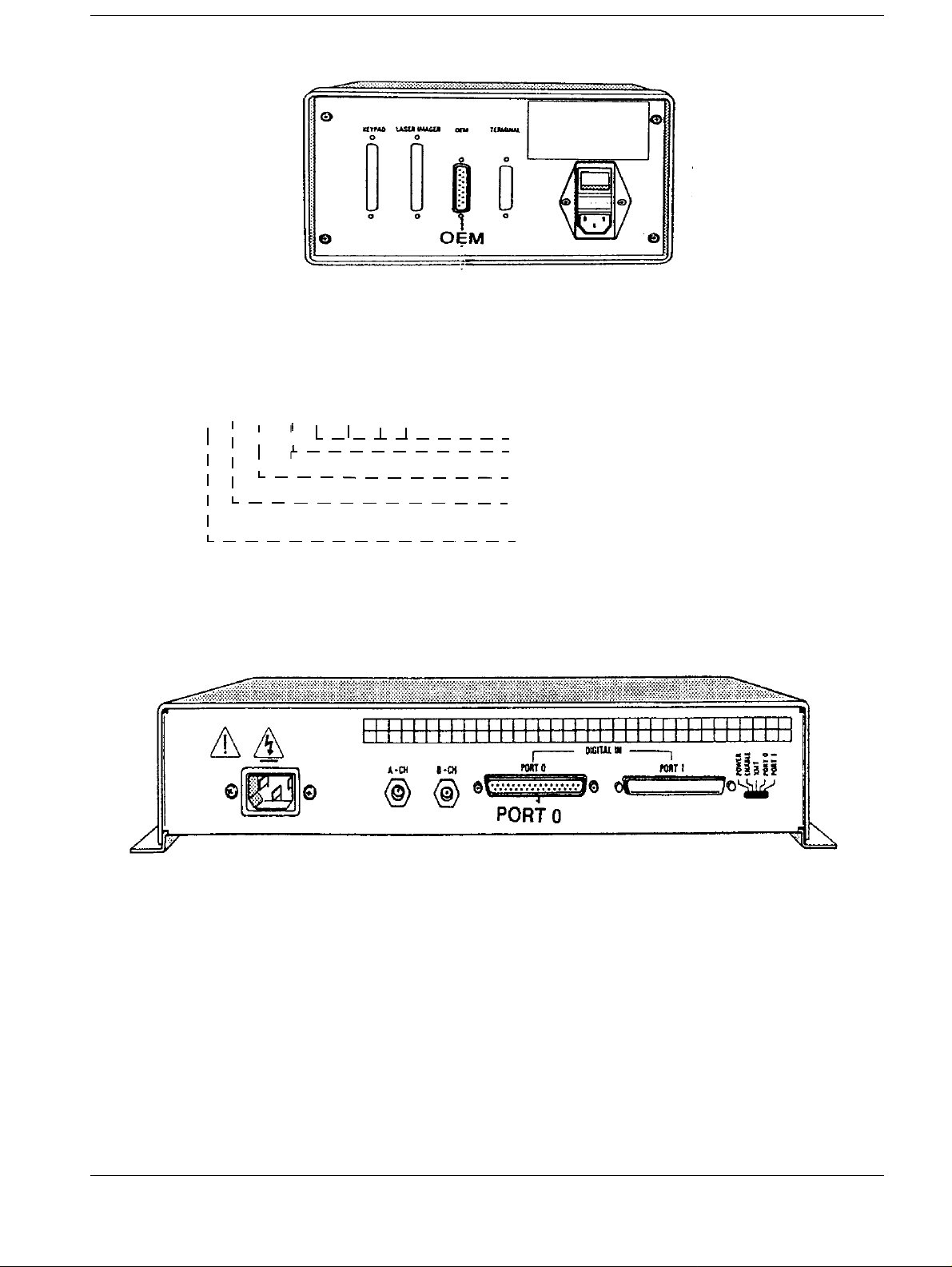
3M HQ (M969 with SHPT). 2
FLUOROSPOT H/HK
Translator
Keypad
TRANSITION
3-M 969/ 959 laser camera
Fiber Optical Cables
KEY
PAD
UKEIB
HOS
DEIB
PORTO
HOST-CONTROL
Fiber Optical cable
IMAGE-DATA-CABLE
PANEL
J 26J 29
Power connection (DEIB*)
POWER
DISTRIB.
*Connected to the same power distribution
UKEIB = Universal Keypad External Interface Box
DEIB = Data External Interface Box
Hardware requirements
Power
connect.
FL-H/HK*
• HCC digital board or VIDEO OUT III board in the FLUOROSPOT is necessary
• OCL (Optical Camera Link) is not necessary
• Cable sets 30/60m: see page 1-2
For the connection of the fiber optical control cable use the opto
decouplers (OZDV) on the TRANSITION Panel and on the UKEIB.
Configuration
In the FLUOROSPOT SYSTEM CONFIGURATION (see page 1-4), set the menu point
”HCC Type” for the 3M 969”3M 959/969-SHPT-2”.
FLUOROSPOT H/HK Register 3 RX41-020.031.01 Page 6 of 22 Siemens AG
Rev. 10 12.96 TD AX 5 Medical Engineering
Page 17

Connection of the camera 2 - 7
Supported formats see page 2-26
The selectable formats are also depending from the memory-expansion of3M HQ
(3M969)
If contrast curve 9 is selected in the 3M XL (3M 959) camera, th e monitor image impression rather coincides with the film.
FLUOROSPOT H/HK TRANSITION PANEL
HCC IMAGE
Fig. 10
J26
J26
J25
SK 111
J32
AUX 2
J22 J23 J24
AC DIST KEYBOARD REMOTE
J27 J28
SERVICE
AUX 1
J29
HCC CTL
Opto Decoupler
RS232 Host Adapter cable
UKEIB
FIBEROPTIC
XMT
FTSW
A-CH B-CH
RCV
Keypad Cable
HOST
KEYPAD
IMAGER
Translator
Keypad
Fig. 11 Fig. 12
Siemens AG Register 3 RX41-020.031.01 Page 7 of 22 FLUOROSPOT H/HK
Medical Engineering Rev. 10 12.96 TD AX 5
Page 18

2 - 8 Connection of the camera
AGFA MCL with AGFA-MIN 2
.Example with OCL
FLUOROSPOT H/HK
AGFA MCL
AGFA MIN
MFRI
*Parts of the Optical Camera Link
Camera
CTR
*
*
CAM.
MOD.
*
TRANSITION
PANEL
J 29
*
Host
*
MOD
Duplex Optical
Fiber Cable*
J 26
*
Hardware requirements 2
• HCC digital board or VIDEO OUT III board in the FLUOROSPOT is necessary
• Whether an OCL is necessary see page 1-1
Configuration 2
For FLUOROSPOT SYSTEM CONFIGURATION (see page 1-4).
For mixed formats ask AGFA Service for camera patch. With patch, load hardcopy driver
”AGFA-MCL- 4”. Respectively without patch load driver
”AGFA-MCL- 3”.
To test the function of the patch start a mixed format hardcopy
Supported formats see page 2-20
FLUOROSPOT H/HK Register 3 RX41-020.031.01 Page 8 of 22 Siemens AG
Rev. 10 12.96 TD AX 5 Medical Engineering
Page 19

Connection of the camera 2 - 9
FLUOROSPOT H/HK TRANSITION PANEL
HCC IMAGE
Fig. 13
.
J26
J26
J25
SK 111
J32
AUX 2
J22 J23 J24
AC DIST KEYBOARD REMOTE
J27 J28
SERVICE
AUX 1
J29
HCC CTL
Other notes
If the ”KANAMORI” curve is selected in the AGFA MCL camera, the monitor image
impression largely coincides with the film.
The AGFA MCL with AGFA MIN is expandable to support up to four image systems.
It is necessary to set the”Autoeject” flag to? Active Auto print function” at the AGFA Cam-
era (performed by the AGFA technical service).
Siemens AG Register 3 RX41-020.031.01 Page 9 of 22 FLUOROSPOT H/HK
Medical Engineering Rev. 10 12.96 TD AX 5
Page 20

2 - 10 Connection of the camera
AGFA MG 3000 + LR 3300. 2
LR 3300
FLUOROSPOT H/HK
AGFA MCL
(alternative
to LR 3300)
AGFA MG 3000
MFRI
Host - Control
Fiber Optical Cable
Image Data Cable
MFRI= Multi Format Receiving Interface
Hardware requirements
TRANSITION
PANEL
J 29
J 26
• HCC DIGITAL BOARD or VIDEO OUT III board in the FLUOROSPOT is necessary
• Whether an OCL is necessary see page 1-1
Configuration
In the FLUOROSPOT SYSTEM CONFIGURATION (see page 1-4) set the menu point
”HCC type” to ”AGFA-MCL-4 or AGFA-MCL-3”.
Supported formats see page 2-20
If the FLUOROSPOT H/HK dedicated LUT (OEM 101 L UT) in t he MG 3 000 is c onfigur ed
the monitor image impression rather coincides with the film.
FLUOROSPOT H/HK Register 3 RX41-020.031.01 Page 10 of 22 Siemens AG
Rev. 10 12.96 TD AX 5 Medical Engineering
Page 21

Connection of the camera 2 - 11
FLUOROSPOT H/HK TRANSITION PANEL
HCC IMAGE
Fig. 14
.
J26
J26
J25
SK 111
J32
AUX 2
J22 J23 J24
AC DIST KEYBOARD REMOTE
J27 J28
SERVICE
AUX 1
J29
HCC CTL
Siemens AG Register 3 RX41-020.031.01 Page 11 of 22 FLUOROSPOT H/HK
Medical Engineering Rev. 10 12.96 TD AX 5
Page 22

2 - 12 Connection of the camera
KODAK XLP / 1120 / 2180 2
Example with OCL.
FLUOROSPOT H/HK
KODAK XLP / 1120 2180
TRANSITION
PANEL
DATA PORT 1
COMMAND PORT 2
*Parts of the Optical Camera Link
Hardware requirements
*
*
Duplex Optical
Fiber Cable *
CAM.
MOD.
*
J
*
Host
MOD.
J
*
*
• HCC digital board or VIDEO OUT III board in the FLUOROSPOT is necessary
• Whether an OCL is necessary see page 1-1
Configuration
In the FLUOROSPOT SYSTEM CONFIGURATION (see page 1-4) select a KODAK hardcopy driver depending on the firmware of the KODAK hardcopy camera. (see page 1-5)
Supported formats see page 2-21
The selectable formats are also depending from the memory-expansion of KODAK camera.
FLUOROSPOT H/HK Register 3 RX41-020.031.01 Page 12 of 22 Siemens AG
Rev. 10 12.96 TD AX 5 Medical Engineering
Page 23

Connection of the camera 2 - 13
NOTICE
FLUOROSPOT H/HK TRANSITION PANEL
HCC IMAGE
Fig. 15
J26
J26
J25
SK 111
J32
AUX 2
J22 J23 J24
AC DIST KEYBOARD REMOTE
J27 J28
SERVICE
AUX 1
J29
HCC CTL
Fig. 16 Fig. 17
If ”CURVE SHAPE 4” is selected in the KODAK XLP or 1120 or
2180 camera, the monitor image impression largely coincides
with the film.
Siemens AG Register 3 RX41-020.031.01 Page 13 of 22 FLUOROSPOT H/HK
Medical Engineering Rev. 10 12.96 TD AX 5
Page 24

2 - 14 Connection of the camera
DU PONT LINX-NET 2
Example with OCL.
LINX-NET
SID-BOX
HCC
connection
adapter
*Parts of the Optical Camera Link
**Parts of the LINX-Net
Hardware requirements 2
not used
**
HOST- CONTR.
*
*
CAM.
MOD.
Duplex Optical
Fiber Cable *
*
FLUOROSPOT H/
TRANSITIO
N
J
*
Host.
MOD.
J
*
*
• HCC digital board or VIDEO OUT III board in the FLUOROSPOT is necessary
• Whether an OCL is necessary see page 1-1
Configuration 2
In the FLUOROSPOT SYSTEM CONFIGURATION (see page 1-4), set the menu point
”HCC type” to ”DIGICAM / LINX NET 2”.
Supported formats see page 2-21
The selectable formats are also depen ding from the memory-expansi on of DIGICAM / DU
PONT cameras.
FLUOROSPOT H/HK Register 3 RX41-020.031.01 Page 14 of 22 Siemens AG
Rev. 10 12.96 TD AX 5 Medical Engineering
Page 25

Connection of the camera 2 - 15
FLUOROSPOT H/HK TRANSITION PANEL
HCC IMAGE
Fig. 18
.
J26
J26
J25
SK 111
J32
AUX 2
J22 J23 J24
AC DIST KEYBOARD REMOTE
J27 J28
SERVICE
AUX 1
J29
HCC CTL
Other notes
The DU PONT laser camera and DIGICAM are identical in design.
KONICA LI10A
Siemens AG Register 3 RX41-020.031.01 Page 15 of 22 FLUOROSPOT H/HK
Medical Engineering Rev. 10 12.96 TD AX 5
Page 26

2 - 16 Connection of the camera
KONICA LI10A 2
Example with OCL
FLUOROSPOT H/HK
TRANSITION
KONICA LASER
IMAGER LI 10A
KEY
PAD
*
CAM
MOD
*
*
J 29
*
HOST
MOD.
PANEL
J 26
*
*
* Parts of the Optical Camera Link (OCL)
Example without OCL
**
KONICA LASER
IMAGER LI 10A
KEY
PAD
MSP 12**
J1HSTCNT
Fiber Optical Cable
J3Host
Duplex Optical
Fiber Cable*
FLUOROSPOT H/HK
TRANSITION
PANEL
J 29
J 26
DataCable
** Parts of Konica installation kit
FLUOROSPOT H/HK Register 3 RX41-020.031.01 Page 16 of 22 Siemens AG
Rev. 10 12.96 TD AX 5 Medical Engineering
Page 27

Connection of the camera 2 - 17
FLUOROSPOT H/HK TRANSITION PANELL
J26
J26
HCC IMAGE
J25
SK 111
Fig. 19
KEYPAD FLUOROSPOT
J1 HSTCNT
J3 HOST
MSP 12
J32
AUX 2
LINE
J22 J23 J24
AC DIST KEYBOARD REMOTE
J27 J28
SERVICE
AUX 1
J29
HCC CTL
Connection Panel Konica Laser
VIDEO2
VIDEO1
CONT2
CONT1
VIDEO4
VIDEO3
CONT4
CONT3
Q7
J1 J2
J3
J4
Command port Data port
Hardware requirements
• HCC digital board or VIDEO OUT III board in the FLUOROSPOT is neces sary
• Whether an OCL is necessary see page 1-1
Configuration 2
In the FLUOROSPOT SYSTEM CONFIGURATION (see page 1-4), set the menu point
”HCC type” to ”KONICA-LI10A-2””.
Supported formats see page 2-22
The configuration of the LI 10A includes a special FL-H LUT.
With this LUT the monitor image impression rat her coincides with the film.
Siemens AG Register 3 RX41-020.031.01 Page 17 of 22 FLUOROSPOT H/HK
Medical Engineering Rev. 10 12.96 TD AX 5
Page 28

2 - 18 Connection of the camera
FUJI FL-IM 3543 2
Example with OCL.
FLUOROSPOT H/HK
FUJI FL-IM 3543
**
*
*Parts of the Optical Camera Link (OCL)
**Part of the Fuji Multi Formatter
FUJI MULTI
FORMATTER
**
*
CAMERA
MODULE
J29
*
HOST
MOD.
*
Duplex Optica
Fiber Cable*
J26
*
*
Hardware requirements 2
• HCC DIGITAL BOARD or VIDEO OUT III board in the FLUOROSPOT is necessary
• Whether an OCL is necessary see page 1-1
Configuration 2
In the FLUOROSPOT SYSTEM CONFIGURATION (see page 1-4), set the menu point
”HCC type” to ”FUJI-3543-P2” for portrait or ”FUJI -3543-L2” for landscape.
Supported formats see page 2-21
The configuration of the Fuji FL-IM 3543 includes a special FL-H LUT.
With this LUT the monitor image impression rather coincides with the film.
FLUOROSPOT H/HK Register 3 RX41-020.031.01 Page 18 of 22 Siemens AG
Rev. 10 12.96 TD AX 5 Medical Engineering
Page 29

Connection of the camera 2 - 19
FLUOROSPOT H/HK TRANSITION PANELL
HCC IMAGE
Fig. 20
J26
J26
J25
SK 111
J32
AUX 2
FUJI Multiformatter
J22 J23 J24
AC DIST KEYBOARD REMOTE
J27 J28
SERVICE
AUX 1
J29
HCC CTL
Data cable
from OCL
Siemens AG Register 3 RX41-020.031.01 Page 19 of 22 FLUOROSPOT H/HK
Medical Engineering Rev. 10 12.96 TD AX 5
Page 30

FLUOROSPOT H/HK Register 3 RX41-020.031.01 Page 20 of 22 Siemens AG
Rev. 10 12.96 TD AX 5 Medical Engineering
2 - 20 Connection of the camera
Sizes and Formats for FLUOROSPOT H formats (images/filmsh e et )
driver name camera size
"3M952-HCI-2" 3M952 (Plus) 14x17
14x17c
3M959/969-HCI-2 3M959 (XL) 14x17
3M969 (HQ) 14x17c
3M959/969-SHPT-2 3M959 (XL) 14x17
3M969 (HQ) 14x17c
AGFA-MCL-3 MCL(solo, MIN, 14x17
+ Spoler) 14x17c
1 2 4 6 8 9 12 15 16 20
1246
24812
1246
24812
1246-9 12 15 16 20 2 + 6 6 + 2 2 + 12 12 + 2 20s
24812-18 24
1246-912-16 20
24812-18 24
--12---
--24--12 15
--
--24---
20
-
---
---
4 + 12 12 + 4
mixed formats
--
Camera driver and supported formats
40s
MG3000+LR3300
AGFA-MCL-4 MCL(solo, MIN, 14x17
+ Spoler) 14x17c
MG3000+LR3300 14x11
14x11c
8x10
8x10c
KODAC-XLP-3 Kodak XLP, 14x17
Kodak 1120 14x17c
1246-912-16 20 2 + 8 8 + 2 3 + 4 4 + 2
24812-18 24
1246-91215-20 3 + 2 2 + 4
24812-18 24
1246-9
24812-18
1246-912151620
24812-18 24
---
--16 20 4 + 4
--
----
---
4 + 16 16 + 4 6 + 8 8 + 4
6 + 4 4 + 8
8 + 8
-
(CPDI 2.2)
KODAK-XLP-4 KODAK-XLP 14x17
(CPDI 2.3) 14x17c
11x14
11x14
14x14
14x14c
1 2 4 6 8 9 12 15 16 20
2 4 8 12161824- - 12468 9 12- - 2 4 8 12161824- - 12468 9 12- 162 4 4 12161824- - -
Page 31

Siemens AG Register 3 RX41-020.031.01 Page 21 of 22 FLUOROSPOT H/HK
Medical Engineering Rev. 10 12.96 TD AX 5
Connection of the camera 2 - 21
formats (images/filmsheet)
KODAK-2180/1120-2 KODAK 2180. 14x17
1 2 8 6 8 9 12 15 16 20
KODAK 1120 14x17c 24812161824 - - -
(CPDI 2.3) 11x14 124 6 8 912 - - -
11x14c 24812161624 - - -
8x10 124 6 - - - - - -
8x10c 24812 - - - - - -
14x14 124 6 8 912 -16 -
14x14c 24812161824 - - -
DIGICAM/LINXNET 2 DIGICAM 14x17 1 2 4 6 8 9 12 15 16 20 1 + 8 2 + 12 6 + 1 9 + 2 12 + 2
LINXNET 14x17c 2 4 8 12 16 18 24 - - - 2 + 16 - 12 + 2 18 + 4
LP400
FUJI-3543-P2 Fuji FL-IM3543 14x17
14x17c
FUJI-3543-L2 Fuji FL-IM3543 14x17
14x17c
1246
24812
1249
24818
12 15
--
--24---
----16-
------
20 1 + 2 1 + 6 6 + 12 9 + 8
2 + 4 2 + 12
2 + 3 3 + 2 2 + 8 8 + 2
4 + 6 6 + 4
-
4 + 16
16 + 4
KonikaLI10A-2 Konika LI10A 14x17 1 2 4 6 8 9 12 15 16 20 2 + 3 3 + 2 2 + 6 6 + 2 2 + 9 9 + 2 12s
14x17c 2 4 8 12 16 18 - - - - 4 + 6 6 + 4 4 + 12 12 + 4 - - 24s
11x14 1 2 4 6 8 9 12 15 16 20 2 + 3 3 + 2 2 + 6 6 + 2 2 + 4 4 + 2 -
11x14c 2 4 8 12 16 18 - - - - 4 + 6 6 + 4 4 + 12 4 + 12 4 + 8 8 + 4 -
14x14 1 2 4 6 - 9 12 15 16 20 - - - - - - 12s
14x14c 2 4 8 12 - 18 - - - - - - - - - - 24s
Page 32

2 - 22 Connection of the camera
This page intentionally left blank.
FLUOROSPOT H/HK Register 3 RX41-020.031.01 Page 22 of 22 Siemens AG
Rev. 10 12.96 TD AX 5 Medical Engineering
Page 33

Service 3
Hardcopy Driver Modification 3
The following problem can be avoided by applying the 3rd disk of the VD12 Software:
Some types of Laser Cameras will l ock, wh en the modality selects a film si ze, which is not
available in the camera. The customer can make a mistake when selecting a film size at
the Fluorospot, which is not supported by the camera.
The following procedure is also described in the file readme.bat on the 3rd disk:
1. Put DISK 3 of the FLH Installation floppy set into your Service PC.
2. Select drive a:.
3. Run the executable file CUSTOM.EXE...
4. Select the original HCC driver. Look at the ta ble below!
5. Answer the questions about the supported fil m size(s) with yes and the
unsupported film size(s) wi th no [n].
6. If you gave a wrong answer, run CUSTOM.EXE once more.
7. Then boot the FLUOROSPOT with your Service PC (ST320) connected.
3 - 1
8. At the Service PC, enter the password to get to th e MAIN Menu. Proceed to the S/
W Installation Menu, then to the RESTORE Menu.
9. Remove the floppy from the Service PC and place it in the FLH floppy drive.
10. Use the RESTORE HCC CONFIGURATION FILES function to copy the new
HCC driver to the FLH. Go back to the S/W Installati on Menu, and select
SYSTEM CONFIGURATION.
11. From the SYSTEM CONFIGURATION Menu, select CHANGE
CONFIGURATION.
12. Choose the HCC driver "CUSTOM" in the FLUOROSPOT configuration menu.
13. Save the new configuration.
14. Switch the FLUOROSPOT off and on again for the new driver to take eff ect.
Tab. 1 Correlation between HCC driver in FLH configuration<>name.def on disk 3
HCC Config Name Disk 3 Driver Name
3M952-HCI-2 3M952B.DEF
3M959/969-HCI-2 3M959B.DEF
3M952-SHPT2 952SHPTB.DEF
3M959/969-SHPT2 959SHPTB.DEF
AGFA-MCL-3 AGFMCL1B.DEF
AGFA-MCL-4 AGFMCL2B.DEF
DIGICAM/LINXNET DIGILNXB.DEF
FUJI-3543-L2 FU3543LB.DEF
Siemens AG Register 3 RX41-020.031.01 Page 1 of 12 FLUOROSPOT H/HK
Medical Engineering Rev. 07 12.96 TD AX 5
Page 34

3 - 2 Service
FUJI-3543-P2 FU3543PB.DEF
KODAK-XLP-3 KODXLP1B.DEF
KODAK-XLP-4 KODXLP2B.DEF
KODAK2180/1120-2 KOD2180B.DEF
KODAK2180/1120-3 K OD2180C. D EF
KONICA-LI10A-2 KOLI10AA.DEF
GENERIC-DIGITAL-2 GENERICB.DEF
ANALOG CAMERAS
AGFA- CR2050-1 AGF2050.DEF
Analog-2 ANALOGB.DEF
MI-11-2 MI11B.DEF
Service Tools for Tracing the SPCI/SPDI Interface 3
There are two tools for troubleshoot ing the Command and DAT A tra nsmission t o and from
the camera.
The first tool is a cheap tool to check the drivers of the Optical Camera Link (OCL) modules, the fiber optic cables, and the hardware signals on the DATA and CONTROL path.
The tool is called Linktest and can be ordered as a spare part with the part number
46 92 177. It consists of two ma in p ar ts :
1. Tester for the Control Interface 3
RS 232 Check Tester
Note: ( only pin 2 and pin 3 are used )
female male
TXD and RXD are monitored via Leds
pin2
pin3
RS232 Check Tester
TD
RD
8-pin modular socket:
1 NC
2 NC
3 NC
4 GND
5 NC
6 RXD
7 TXD
8 +5V
The Control Interface of the Fluorospot can be tested with the help of the Loop Back
Connector, which is part of the CTX accessories. The Loop Back makes a connection
FLUOROSPOT H/HK Register 3 RX41-020.031.01 Page 2 of 12 Siemens AG
Rev. 07 12.96 TD AX 5 Medical Engineering
Page 35

Service 3 - 3
between pin 2 and 3, so that one can test the control interface of the FLH by starting the
Loop Back Test in the service menu Interface Tests.
The Check Tester can be used to display the RXD and TXD signals.
The Loop Back Connector can be plugged into transition panel of the FLH or into the
SPCI output of the OCL on camera side. The loop back can not be used to check the
Hirschmann modules, because they need the power supply from the camera.
2. Linktest Board 3
The link test board consists of three independent functional units:
a) 13 LED pairs to display the s tatus of the 13 RS485 lines of the par allel camera in terface
SPDI:
DATA0 to DATA7, PAR, CLOCK, MODSEL and DAREQ, REP.
This display functions even without power supply via the OCL fibre optic link.
b) 2 LED pairs to monitor the RS232 lines of the SPCI interface:
RXD and TXD.
Functions only if used with the OCL fibre optic link.
c) Test signal generator: In connection with a short-circuit cable, it actively tests the function of the OCL fibre optic link FOC path in both directions (fla shing red and green SPCI
TEST LED); for this purpose, press the TEST-ON key. No host and camera connection is
necessary for the test.
For functional testing of the SPDI drivers, press the DAREQ-ON key (functions only if
used with the OCL fibre optic link). The link test board is fully transparent for the dat a of
the SPCI and SPDI interface if neither the TEST-ON key nor the DAREQ-ON key has
been pressed! Therefore, it may remain inserted in the cable during normal operation of
the camera interface.
LED circuits:
SPCI: SPDI:
+/- 8 to 13 VDC
470 Ohm
RXD
DATA0
470 Ohm
red
Siemens AG Register 3 RX41-020.031.01 Page 3 of 12 FLUOROSPOT H/HK
Medical Engineering Rev. 07 12.96 TD AX 5
green
GND
red
green
DATA0
Page 36

3 - 4 Service
LED schematics and pin allocation table:
WP Linktest
Data 0
Data 1
Data 2
Data 3
Data 4
Data 5
Data 6
Data 7
PAR
CLOCK
MODSEL
DAREQ
REP
male
female
SPCI
TEST
ON
SPCI
TEST
RXD
TXD
DAREQ
ON
used for :
SPCI SPDI
Pin allocation table of the link test board:
Female connector Sub-D Male connector Sub-D
1 Shield / GND Shield / GND
2NC NC
3REP REP
4 DAREQ DAREQ
5 MODSEL MODSEL
6 CLOCK CLOCK
7PAR PAR
8DATA7 DATA7
9DATA6 DATA6
10 DATA5 DATA5
11 DATA4 DATA4
12 DATA3 DATA3
13 DATA2 DATA2
14 DATA1 DATA1
15 DATA0 DATA0
16 NC NC
17 NC NC
18 TXD NC/TXD as from update level (Äst) 03 of OPSP
19 RXD NC/RXD as from update level (Äst) 03 of OPSP
20 +5V GND
21 NC NC
22 REP* REP*
23 DAREQ* DAREQ*
24 MODSEL* MODSEL*
25 CLOCK* CLOCK*
26 PAR* PAR*
27 DATA7* DATA7*
28 DATA6* DATA6*
FLUOROSPOT H/HK Register 3 RX41-020.031.01 Page 4 of 12 Siemens AG
Rev. 07 12.96 TD AX 5 Medical Engineering
Page 37

Service 3 - 5
29 DATA5* DATA5*
30 DATA4* DATA4*
31 DATA3* DATA3*
32 DATA2* DATA2*
33 DATA1* DATA1*
34 DATA0* DATA0*
35 NC NC
36 NC NC
37 GND +5V
• Start of image transfer
The image transfer is initiate d by marking images in postprocessing mode and sendi ng
them from the FLH memory via the hardcopy interfa ce (HCC or Vid Out3 board) with the
button HARDCOPY SINGLE or HARDCOPY MULTI to the laser camera.
• SPCI error
After the job has been started, the FLH communic ates with the laser camera. Film size,
format and other parameters are sent t o the camera, if the camera is re ady. If not, the
FLH displays the message ’camera does not seem to be connected’.
• SPDI error
When there is no problem in communication via SPCI i nterface and the camera is ready
for data transmission - the camera rece ived the necessary parameters from the FLH- ,
the FLH waits for the signal DATA REQUEST on the SPDI from the camera. I f the
camera does not request any data within a ce rtain time (less than 1 minute) or i f there is
a timing error, the FLH display s the message ’error in data transmission’. The FL H
tries to resend the HCC background job after a certain timeout.
• Image transmission
The data transfer begins, when the communicati on via SPCI works and when the
parameters for the camera has been transmi tted from the FLH. After this handshake, the
image is sent via SPDI to the Laser Camera, when the following timing is ok:
SPDI Diagram
Siemens AG Register 3 RX41-020.031.01 Page 5 of 12 FLUOROSPOT H/HK
Medical Engineering Rev. 07 12.96 TD AX 5
Page 38

3 - 6 Service
The signals can be measured with 5V level on the Vid Out 3 board as follows:
Camera signal DATA REQUEST U1200.3
FLH CLOCK U1211.9
FLH MOD SELECT U1211.7
FLH PARITY EVEN U1211.1
Check of the OCL 3
Status LED green: Hardware is ok
Status LED red blinking:
Cause:
- fibre optic cable may be defective
- the OCL box on the other side may be
defective or without mains
Camera Interface Test System 3
• Purpose
The CITS (Camera Interface Test System) enab les the user to record communications
between Laser Cameras and Imaging Systems and to look into the SPCI and SPDI
communication.
It records the transmissio n of image information and contro ls information. It monitors the
conformity in respect to the i nterface protocols and detects errors within the syntax of
the control commands.
Digital Laser Cameras are simulated by ut ilizing their own control commands (Camera
Mode).
Previously recorded information can again be analyzed by means of the “Postanalys is
Mode“.
Status LED
Function
Opto
• Elements
The tool consists of a box with several connectors and some LEDs. Cables are included
to connect this box to:
- Line Voltage, Service PC, SPCI In terface, SPDI Interface
• Application
The CITS box is controlled by the CAMWIN software, which runs on a Service PC,
connected to the control input of the box. The software is a Windows applicati on.
• Result
The result of listening the SPCI and SPDI int erface is stored in a *.ctl fi le. This file looks
like the following.
FLUOROSPOT H/HK Register 3 RX41-020.031.01 Page 6 of 12 Siemens AG
Rev. 07 12.96 TD AX 5 Medical Engineering
Page 39

Service 3 - 7
******* CITS USP/SPCI/SPDI-PROTOCOL-A NALYSER VERSION 0.4 *******
PARAMETERS OF RECORDING:
CAMERA-TYPE: 3M M9 59 XL
MODALITY-TYPE:Fluorospot H
DATE OF RECORDING:05/20/1994
TIME OF RECORDING:15:47:58
PARAMETERS OF ANALYSIS :
MODE: POST-ANALYSIS OF LISTENER
RECORDING:ALL
DATE OF ANALYSIS:05/24/1994
TIME OF ANALYSIS:10:32:00
************************ START OF ANALYSIS ************************
15:48:11,426 Mod: 2h; STXStart of TeXt
15:48:11,430 Mod: xa1; Select serial control port 1
15:48:11,444 Mod: 3h; ETXEnd of TeXt
15:48:11,451 Cam: 13h; RNR0Receiver Not Ready 0
15:48:11,456 Cam: 11h; RR0Receiver Ready 0
15:48:11,491 Cam: 2h; STXStart of TeXt
15:48:11,495 Cam: xa1; Serial control port 1 selected
15:48:11,509 Cam: 3h; ETXEnd of TeXt
15:48:11,515 Mod: 13h; RNR0Receiver Not Ready 0
15:48:11,519 Mod: 11h; RR0Receiver Ready 0
15:48:11,555 Mod: 2h; STXStart of TeXt
15:48:11,559 Mod: ?\; Query camera status
15:48:11,569 Mod: 3h; ETXEnd of TeXt
15:48:11,575 Cam: 14h; RNR1Receiver Not Ready 1
15:48:11,580 Cam: 12h; RR1Receiver Ready 1
15:48:11,612 Cam: 2h; STXStart of TeXt
15:48:11,617 Cam: \>51-0010210; Camera status
15:48:11,671 Cam: 3h; ETXEnd of TeXt
15:48:11,676 Mod: 14h; RNR1Receiver Not Ready 1
15:48:11,681 Mod: 12h; RR1Receiver Ready 1
15:48:11,695 Mod: 2h; STXStart of TeXt
15:48:11,700 Mod: ?/; Query exposure status
15:48:11,708 Mod: 3h; ETXEnd of TeXt
15:48:11,716 Cam: 13h; RNR0Receiver Not Ready 0
15:48:11,719 Cam: 11h; RR0Receiver Ready 0
.
*********************** ANALYSIS-STATISTICS ***********************
CLOSEDATE OF RECORDING:05/24/1994
CLOSETIME OF RECORDING:10:40:25
COUNT OF DETECTED
RTC-INTERRUPTS:1290
COUNT OF SUPERNUMERARY
RTC-INTERRUPTS:265
************************* END OF ANALYSIS *************************
• Order information
The CITS (without PC) can be ordered with Siemens part number 99 00 531. CAMWIN
software is included.
Siemens AG Register 3 RX41-020.031.01 Page 7 of 12 FLUOROSPOT H/HK
Medical Engineering Rev. 07 12.96 TD AX 5
Page 40

3 - 8 Service
Hardcopy Error Messages 3
The hardcopy errors, displayed on the Fl uorospot H monitor, are initiated by the hardcopy
cameras. The error codes are only converted in the Fluorospot to the error codes, which
originally were specified for the DIGICAM Laser camera.
For error interpretation, detailed information can be obtained by means of the camera
error code contained in the camera documentation of the manufactur er.
FL-H/HK display 3M laser
713
811
10 12
11 10
13 20, 21
14 22-28
17 29-31, 37
17 40-42, 79-85
19 14-16
24 54
31 39, 56-59
35 6
41 96
42 38, 47-53
42 72, 76-78
43 92-95, 98
50 18
52 17
53 33
57 1, 2, 5, 7, 9, 19, 43-46
57 60-71
57 87- 91, 97
69 55, 73-75
69 86
70 99
80 3
82 4
86 0,8
FLUOROSPOT H/HK Register 3 RX41-020.031.01 Page 8 of 12 Siemens AG
Rev. 07 12.96 TD AX 5 Medical Engineering
Page 41

Service 3 - 9
KODAK XLP AGFA MCL-LASER
FL-H/HK KODAK XLP FL-H/HK MCL
00 05, 29, 35, 39, 54 10 30
00 59, 65, 73, 74 11 33
07 02 18 20, 41, 47, 49
08 04 35 05, 06, 17, 18
10 01 50 32
11 03 52 31,44
11 09 57 45
34 25 70 07
35 81 83 1, 08, 42, 43
50 06 84 02, 03, 04, 40, 46
57 62, 64 86 19
80 55
83 31-34, 40, 53
Siemens AG Register 3 RX41-020.031.01 Page 9 of 12 FLUOROSPOT H/HK
Medical Engineering Rev. 07 12.96 TD AX 5
Page 42

3 - 10 Service
KONICA LI-10A
FL-H / HK KONICA Laser
7 301B
301C
8 3065
10 3019
301A
11 301E
18 300A
300B
21 4180
34
35 510E
5125
35
44 4181
4190
50 3032
69
73 301F
3020
3021
3023
3024
3028
300C
300D
3014
3015
3016
3018
FLUOROSPOT H/HK Register 3 RX41-020.031.01 Page 10 of 12 Siemens AG
Rev. 07 12.96 TD AX 5 Medical Engineering
Page 43

Service 3 - 11
FL-H / HK KONICA Laser
75
78 3035
3036
3037
3038
80
83
85 2903
88
92 303C
93 303D
96
99
FUJI FL-IM 3543
FLUOROSPOT H/HK FUJI-Laser
06 01, 02, 23, 24, 52, 53
10 13
11 12
18 06, 15-21, 51, 54-61
31 11
52 51, 61
57 22,25
80 05
83 07
97 10, 14
Siemens AG Register 3 RX41-020.031.01 Page 11 of 12 FLUOROSPOT H/HK
Medical Engineering Rev. 07 12.96 TD AX 5
Page 44

3 - 12 Service
This page intentionally left blank.
FLUOROSPOT H/HK Register 3 RX41-020.031.01 Page 12 of 12 Siemens AG
Rev. 07 12.96 TD AX 5 Medical Engineering
Page 45

Abbreviations 4
CPU Central Processing Unit
CTR Control
DEIB Data External Interface Box
FOC Fiber Opti cal Cable
HCC Hardcopy Camera
HCI Host Control Interface
KEIB Keypad External Interface Box
LUT Lookup Table
MCL Matrix Laser Camera
MFRI Multi Format Receiving Interface
MG Medical Gateway
MIN Matrix Image Network
OCL Optical Camera Link
OEM Original Equipment Manufacturer
PC Personal Computer
SHPT Siemens Host Protocol Translator
SID-BOX Scanner interface Device Box
UKEIB Universal External Interface Box
4 - 1
Siemens AG Register 3 RX41-020.031.01 Page 1 of 2 FLUOROSPOT H/HK
Medical Engineering Rev. 02 12.96 TD AX 5
Page 46

4 - 2 Abbreviations
This page intentionally left blank.
FLUOROSPOT H/HK Register 3 RX41-020.031.01 Page 2 of 2 Siemens AG
Rev. 02 12.96 TD AX 5 Medical Engineering
Page 47

Changes to Previous Version 5
All pages: New layout.
5 - 1
Chap.0 Page 1:
Page 2,3,4:
Chap.1 Page 2: Chap "Units without OCL" expanded.
Chap.2 Page 20/21:
Page22,23,24
Chap.3 New.
Chap.5 Page 1: Updated.
Date, Revision level changed.
Revision level table, table of contents updated.
Tables expanded.
New.
TD AX 5 / Blum
TD AX 1 / Biedermann
Siemens AG Register 3 RX41-020.031.01 Page 1 of 2 FLUOROSPOT H/HK
Medical Engineering Rev. 01 12.96 TD AX 5
Page 48

5 - 2 Changes to Previous Version
This page intentionally left blank.
FLUOROSPOT H/HK Register 3 RX41-020.031.01 Page 2 of 2 Siemens AG
Rev. 01 12.96 TD AX 5 Medical Engineering
 Loading...