

Page 1

FUJI-Reader
Service Manual
SP
Checks, Replacement and Adjustment of Parts
© Siemens AG 2003
The reproduction, transmission or
use of this document or its contents
is not permitted without express
written authority. Offenders will be
liable for damages. All rights,
including rights created by patent
grant or registration of a utility
model _or_ design,_are_ reserved.
English
Print No.: SPB7-420.840.53.01.02 Doc. Gen. Date: 01.03
Replaces: n.a.
Page 2

CR-IR347/CR-IR347P
Service Manual
Checks, Replacement and Adjustment
of Parts (MC)
Page 3

Contents Maintenance Checks, Replacement and Adjustment of Parts
0.1
CR-IR347 Service Manual – Contents
Checks, Replacement and Adjustment of Parts (MC)
1. Check/Adjustment Procedures for Each Unit............................................................ MC-2
2. Table of Contents ......................................................................................................... MC-4
3. Removing and Installing the Covers .......................................................................... MC-8
4. Removing and Installing the Cassette Set Unit......................................................... MC-10
4.1 Cassette Set Unit ............................................................................................... MC-10
4.2 Shutter ................................................................................................................ MC-12
4.3 Cassette Ejection Sensor (SK1) ....................................................................... MC-14
4.4 Barcode Reader (BCRK1).................................................................................. MC-16
4.5 Pulling Out the Tray ........................................................................................... MC-20
4.6 Cassette Hold Solenoid (SOLK1) ..................................................................... MC-26
4.7 Cassette Hold Sensor (SK3) ............................................................................. MC-32
4.8 Claw Guide Assembly ....................................................................................... MC-34
4.9 Cassette IN Sensor (SK2) .................................................................................. MC-40
4.10 Rubber Roller ..................................................................................................... MC-50
4.11 Guide Plate ......................................................................................................... MC-52
4.12 Guide Stoppers .................................................................................................. MC-64
4.13 Movable Guides ................................................................................................. MC-66
5. Removing and Installing the IP Removal Unit ........................................................... MC-74
5.1 IP Removal Unit.................................................................................................. MC-74
5.2 IP Leak Valve (SVL1).......................................................................................... MC-78
5.3 Suction Cup HP Sensor (SL1)........................................................................... MC-80
5.4 Timing Belt (for IP Conveyance)....................................................................... MC-86
5.5 Guide Plate A...................................................................................................... MC-90
5.6 Rubber Rollers C and D..................................................................................... MC-92
5.7 Rubber Roller (Large) ........................................................................................ MC-94
5.8 Guide Plate D...................................................................................................... MC-96
5.9 Guide Plates B and C......................................................................................... MC-98
5.10 Supports (for IP Removal Arm) ........................................................................ MC-100
5.11 Suction Cups ......................................................................................................MC-104
5.12 IP Suction Pump (PL1) ...................................................................................... MC-108
5.13 Inch/Metric Sensor (SL4) ...................................................................................MC-110
5.14 Suction Sensor (SL5)......................................................................................... MC-112
5.15 Receiver Rollers .................................................................................................MC-114
5.16 Guide Plates E, F, and G ................................................................................... MC-118
5.17 Suction Cup Driving Motor (ML1) ..................................................................... MC-120
009-058-03
08.30.2002 FM3476
CR-IR347
Service Manual
0.1
Page 4

Contents Maintenance Checks, Replacement and Adjustment of Parts
5.18 Timing Belt (for Suction Cup Drive) .................................................................MC-122
5.19 Shaft (for Suction Cup Drive)............................................................................ MC-124
5.20 IP Removal Unit Upper Assembly ....................................................................MC-128
5.21 Rubber Roller A.................................................................................................. MC-130
5.22 IP Transport Motor (ML2) ..................................................................................MC-132
5.23 Shaft (for IP Conveyance) .................................................................................MC-134
5.24 Rubber Roller B.................................................................................................. MC-136
6. Removing and Installing the Erasure Conveyor ....................................................... MC-138
6.1 Erasure Lamp Assembly ...................................................................................MC-138
6.2 Erasure Conveyor ..............................................................................................MC-140
0.2
6.3 Cleaning Roller Assembly................................................................................. MC-144
6.4 Cleaning Rollers................................................................................................. MC-146
6.5 Erasure Lamps (LAMP1-LAMP5) ......................................................................MC-148
6.6 Erasure Thermostatic Switch (TSW2) ..............................................................MC-150
6.7 Erasure Thermostatic Switch (TSW1) ..............................................................MC-152
6.8 Erasure Cooling Fan (FANM1) ..........................................................................MC-154
6.9 Sockets ...............................................................................................................MC-156
6.10 Timing Belts ....................................................................................................... MC-160
6.11 Lamp House Assembly ..................................................................................... MC-164
6.12 Filter ....................................................................................................................MC-166
6.13 Reflection Plate ..................................................................................................MC-168
6.14 IP Transport Motor (MM1) ................................................................................. MC-170
6.15 Rubber Rollers (Upper) ..................................................................................... MC-172
6.16 Light Protect Plates ...........................................................................................MC-174
6.17 Rubber Rollers (Lower) .....................................................................................MC-176
6.18 Guide Plates .......................................................................................................MC-178
7. Pulling Out and Pushing In the Scanner Unit............................................................ MC-182
009-058-03
08.30.2002 FM3476
CR-IR347
Service Manual
0.2
Page 5

Contents Maintenance Checks, Replacement and Adjustment of Parts
8. Removing and Installing the Side-Positioning Conveyor......................................... MC-188
8.1 Side-Positioning Conveyor ...............................................................................MC-188
8.2 Grip Release Motor (MN2) .................................................................................MC-192
8.3 Barcode Reader (BCRN1).................................................................................. MC-194
8.4 Side-Positioning Mechanism HP Sensor (SN1) .............................................. MC-196
8.5 Grip Release HP Sensor (SN2) ......................................................................... MC-198
8.6 Cleaning Guide Drive Motor (MN4)................................................................... MC-200
8.7 BCR08A Board ...................................................................................................MC-202
8.8 Side-Positioning IP Sensor (SN3)..................................................................... MC-204
8.9 Cleaning Guide HP Sensor (SN4) .....................................................................MC-206
0.3
8.10 Cleaning Guide Assembly................................................................................. MC-208
8.11 Shaft (for Cleaning Guide Assembly) .............................................................. MC-214
8.12 Guide Plate C...................................................................................................... MC-218
8.13 Timing Belt (for IP Conveyance)....................................................................... MC-220
8.14 Guide Plate G ..................................................................................................... MC-222
8.15 Rubber Rollers (Rear) ........................................................................................MC-226
8.16 Wires (Left Side)................................................................................................. MC-230
8.17 Wires (Right Side) ..............................................................................................MC-234
8.18 Timing Belt (for Side-Positioning Mechanism) ...............................................MC-240
8.19 Shaft (for Grip Release) .....................................................................................MC-246
9. Removing and Installing the Scanning Optics Unit ..................................................MC-250
9.1 Adjusting the Format ......................................................................................... MC-250
9.2 Shading and Sensitivity Corrections ...............................................................MC-254
9.3 Checking for Image Problems ..........................................................................MC-258
9.4 Removing and Installing the Scanning Optics Unit........................................ MC-262
9.5 LD Assembly ......................................................................................................MC-266
9.6 Polygon Assembly ............................................................................................. MC-270
9.7 SYN08A Board.................................................................................................... MC-274
009-058-03
08.30.2002 FM3476
CR-IR347
Service Manual
0.3
Page 6

Contents Maintenance Checks, Replacement and Adjustment of Parts
10. Removing and Installing the Subscanning Unit........................................................ MC-278
10.1 Driving-Side Grip Release HP Sensor (SZ2).................................................... MC-278
10.2 Mirror HP Sensor (SZ4) ..................................................................................... MC-280
10.3 Rubber Belt and SUS Belt .................................................................................MC-282
10.4 Kapton® Belt ......................................................................................................MC-284
10.5 Flywheel ..............................................................................................................MC-286
10.6 Subscanning Motor MZ1 (FFM) ........................................................................ MC-288
10.7 PMT08D Board ................................................................................................... MC-292
10.8 PMR08C Board ...................................................................................................MC-296
10.9 Light-Collecting Guide Assembly (for Front Surface) .................................... MC-300
0.4
10.10 Light-Collecting Guide Assembly (for Back Surface) .................................... MC-308
10.11 Light-Collecting Mirror and IP Leading-Edge Sensor (SZ1/SED08D) ........... MC-320
10.12 Glass Guide ........................................................................................................MC-326
10.13 Lower Rubber Rollers........................................................................................ MC-332
10.14 Mirror Driving Motor (MZ4)................................................................................ MC-336
10.15 Driving-Shaft Grip Motor (MZ2) ........................................................................ MC-338
10.16 Driven-Shaft Grip Motor (MZ3).......................................................................... MC-342
10.17 Driven-Side Grip Release HP Sensor (SZ3) .....................................................MC-346
10.18 Subscanning Unit Controller Assembly ..........................................................MC-348
10.19 SCN08D/SCR08D Board ....................................................................................MC-354
10.20 PHV08D Board.................................................................................................... MC-358
11. Removing and Installing the Hard Disk Drive (HDD) ................................................MC-360
11.1 Setting HDD ........................................................................................................MC-361
11.2 Hard Disk Drive (HDD) .......................................................................................MC-362
12. Removing and Installing the Floppy Disk Drive (FDD) ............................................. MC-372
12.1 Setting FDD ........................................................................................................ MC-372
12.2 Floppy Disk Drive (FDD) .................................................................................... MC-372
009-058-03
08.30.2002 FM3476
CR-IR347
Service Manual
0.4
Page 7

Contents Maintenance Checks, Replacement and Adjustment of Parts
13. Removing and Installing the Power Supply Unit (JPS-6) .........................................MC-374
13.1 Power Supply Unit (JPS-6) ................................................................................MC-374
13.2 Power Supply Unit Fuses ..................................................................................MC-378
14. Removing and Installing the Monitor ......................................................................... MC-382
14.1 CRT (Monitor) .....................................................................................................MC-382
14.2 Fuse Between Power Supply Unit and CRT ....................................................MC-388
15. Removing and Installing the PC Boards ....................................................................MC-390
15.1 MTH08C Board ...................................................................................................MC-402
15.2 MTH08D Board ...................................................................................................MC-404
15.3 CPU90E Board.................................................................................................... MC-406
0.5
15.4 IMG07B Board ....................................................................................................MC-410
15.5 BSP08A Board.................................................................................................... MC-411
15.6 IMG08M Board ....................................................................................................MC-413
15.7 CPU90F Board (Optional) ..................................................................................MC-414
15.8 LAN90B Board (Optional).................................................................................. MC-416
15.9 HCP08A Board (Optional) ................................................................................. MC-417
15.10 IMG08H Board (Optional) ..................................................................................MC-418
15.11 SNS08C and DRV08A Boards ...........................................................................MC-420
15.12 VOL08A Board.................................................................................................... MC-427
15.13 LED08A Board ....................................................................................................MC-428
15.14 LED08B Board ....................................................................................................MC-428
15.15 BCR08A Board ...................................................................................................MC-429
15.16 SYN08A, PMT08D, PMR08C, SCN08D/SCR08D, and PHV08D boards .......... MC-429
009-058-03
08.30.2002 FM3476
CR-IR347
Service Manual
0.5
Page 8

Checks, Replacement and Adjustment of Parts (MC) Control Sheet
Control Sheet
Issue date
10/20/2000 00 New release (FM2732) All pages
05/15/2001 01 Corrections (FM3052) MC - 9, 93, 146, 265, 331
08/30/2001 02 Design changes; measures against noise MC - 25, 91, 93, 95, 130, 131,
08/30/2002 03 Scanning optics unit, HDD, and other MC - 6, 7, 33, 37, 148, 254–261,
Revision number Reason Pages affected
(FM3142) 137, 142-145, 161-162, 173, 177,
information added (FM3476) 261.1–261.4, 262–265,
MC - 1
178, 180, 183, 184, 208-210, 214,
215, 223-225, 227-229, 241, 244,
245, 263, 267, 271, 275, 327,
328, 331, 333, 334, 349-353,
353.1-353.8, 361, 361.1-361.4,
362, 401
265.1–265.8, 275, 293, 297,
356, 357, 359–429
009-058-03
08.30.2002 FM3476
CR-IR347
Service Manual
MC - 1
Page 9
MC - 2
1. Check/Adjustment Procedures for Each Unit
Precautions for Check, Replacement, and Adjustment
In this volume, descriptions are omitted regarding components that do not require special
attention or adjustment during their removal/reinstallation. For removal procedures for such
components, refer to the Parts List Volume.
When performing check/replacement/adjustment procedures on the machine, the following
precautions should be observed.
WARNING
To avoid electric shock hazards, power OFF the machine before performing the
procedures.
WARNING/CAUTION
Observe the warnings and cautions described in the “Safety Precautions.”
CAUTION
Never remove screws to which red paint is applied.
◆
INSTRUCTION
Screws to which yellow paint is applied need to be adjusted at the time of component
installation. When installing a component, follow the specified check/adjustment
procedure.
Some of the illustrations in this volume contain check/adjustment and half-punch indicators
as needed.
For removal and reinstallation, perform the procedures as instructed by such indicators.
• Check/Adjustment indicator: Indicates that it is necessary to check or adjust the
CHECK
◆
installation location when the part or component removed is
to be reinstalled.
This indicator is placed in the illustration that depicts the
procedures for removing the parts and components.
When you see this indicator, refer to its relevant “■ Check/
Adjustment Procedures.”
• Half-punch indicator: Indicates that it is necessary to align the half-punches when
009-058-00
10.20.2000 FM2732 (2)
installing the parts or components.
However, it is not indicated for the half-punches for
improving ease of assembly or preventing erroneous
assembly procedures.
CR-IR347
Service Manual
MC - 2
Page 10

BLANK PAGE
MC - 3
009-058-00
10.20.2000 FM2732 (2)
CR-IR347
Service Manual
MC - 3
Page 11

2. Table of Contents
MC - 4
3. Covers
4. Cassette set unit
3. Removing and Installing the Covers MC-8
4. Removing and Installing the Cassette Set Unit MC-10
4.1 Cassette Set Unit MC-10
4.2 Shutter MC-12
4.3 Cassette Ejection Sensor (SK1) MC-14
4.4 Barcode Reader (BCRK1) MC-16
4.5 Pulling Out the Tray MC-20
4.6 Cassette Hold Solenoid (SOLK1) MC-26
4.7 Cassette Hold Sensor (SK3) MC-32
4.8 Claw Guide Assembly MC-34
4.9 Cassette IN Sensor (SK2) MC-40
4.10 Rubber Roller MC-50
4.11 Guide Plate MC-52
4.12 Guide Stoppers MC-64
4.13 Movable Guides MC-66
5. IP Removal Unit
5. Removing and Installing the IP Removal Unit MC-74
5.1 IP Removal Unit MC-74
5.2 IP leak valve (SVL1) MC-78
5.3 Suction Cup HP Sensor (SL1) MC-80
5.4 Timing Belt (for IP Conveyance) MC-86
5.5 Guide Plate A MC-90
5.6 Rubber Rollers C and D MC-92
5.7 Rubber Roller (Large) MC-94
5.8 Guide Plate D MC-96
5.9 Guides Plates B and C MC-98
5.10 Supports (for IP Removal Arm) MC-100
5.11 Suction Cups MC-104
5.12 IP Suction Pump (PL1) MC-108
5.13 Inch/Metric Sensor (SL4) MC-110
5.14 Suction Sensor (SL5) MC-112
5.15 Receiver rollers MC-114
5.16 Guide Plates E, F, and G MC-118
5.17 Suction Cup Driving Motor (ML1) MC-120
5.18 Timing Belt (for Suction Cup Drive) MC-122
5.19 Shaft (for Suction Cup Drive) MC-124
5.20 IP Removal Unit Upper Assembly MC-128
5.21 Rubber Roller A MC-130
5.22 IP Transport Motor (ML2) MC-132
5.23 Shaft (for IP Conveyance) MC-134
5.24 Rubber Roller B MC-136
FR7H30AC.EPS
009-058-00
10.20.2000 FM2732 (2)
CR-IR347
Service Manual
MC - 4
Page 12
MC - 5
6. Erasure conveyor
7. Scanner unit
6. Removing and Installing the Erasure Conveyor MC-138
6.1 Erasure Lamp Assembly MC-138
6.2 Erasure Conveyor MC-140
6.3 Cleaning Roller Assembly MC-144
6.4 Cleaning Rollers MC-146
6.5 Erasure Lamps (LAMP1-LAMP5) MC-148
6.6 Erasure Thermostatic Switch (TSW2) MC-150
6.7 Erasure Thermostatic Switch (TSW1) MC-152
6.8 Erasure Cooling Fan (FANM1) MC-154
6.9 Sockets MC-156
6.10 Timing Belts MC-160
6.11 Lamp House Assembly MC-164
6.12 Filter MC-166
6.13 Reflection Plate MC-168
6.14 IP Transport Motor (MM1) MC-170
6.15 Rubber Rollers (Upper) MC-172
6.16 Shielding Plates MC-174
6.17 Rubber Rollers (Lower) MC-176
6.18 Guide Plates MC-178
7. Pulling Out and Pushing In the Scanner Unit MC-182
8. Side-positioning conveyor
8. Removing and Installing the Side-Positioning Conveyor MC-188
8.1 Side-Positioning Conveyor MC-188
8.2 Grip Release Motor (MN2) MC-192
8.3 Barcode Reader (BCRN1) MC-194
8.4 Side-Positioning Mechanism HP Sensor (SN1) MC-196
8.5 Grip Release HP Sensor (SN2) MC-198
8.6 Cleaning Guide Drive Motor (MN4) MC-200
8.7 BCR08A Board MC-202
8.8 Side-Positioning IP Sensor (SN3) MC-204
8.9 Cleaning Guide HP Sensor (SN4) MC-206
8.10 Cleaning Guide Assembly MC-208
8.11 Shaft (for Cleaning Guide Assembly) MC-214
8.12 Guide Plate C MC-218
8.13 Timing Belt (for IP Conveyance) MC-220
8.14 Guide Plate G MC-222
8.15 Rubber Rollers (Rear) MC-226
8.16 Wire (Left Side) MC-230
8.17 Wires (Right Side) MC-234
8.18 Timing Belt (for Side-Positioning Mechanism) MC-240
8.19 Shaft (for Grip Release) MC-246
FR7H30AD.EPS
009-058-00
10.20.2000 FM2732 (2)
CR-IR347
Service Manual
MC - 5
Page 13
MC - 6
9. Scanning optics unit
10. Subscanning unit
9. Removing and Installing the Scanning Optics Unit MC-250
9.1 Adjusting the Format MC-250
9.2 Shading and Sensitivity Corrections MC-254
9.3 Checking for Image Problems MC-258
9.4 Removing and Installing the Scanning
Optics Unit MC-262
9.5 LD Assembly MC-266
9.6 Polygon Assembly MC-270
9.7 SYN08A Board MC-274
10. Removing and Installing the Subscanning Unit MC-278
10.1 Driving-Side Grip Release HP Sensor (SZ2) MC-278
10.2 Mirror HP Sensor (SZ4) MC-280
10.3 Rubber Belt and SUS Belt MC-282
10.4 Kapton
10.5 Flywheel MC-286
10.6 Subscanning Motor MZ1 (FFM) MC-288
10.7 PMT08D Board MC-292
10.8 PMR08C Board MC-296
10.9 Light-Collecting Guide Assembly
10.10 Light-Collecting Guide Assembly
10.11 Light-Collecting Mirror and IP Leading-Edge
10.12 Glass Guide MC-326
10.13 Lower Rubber Rollers MC-332
10.14 Mirror Driving Motor (MZ4) MC-336
10.15 Driving-Shaft Grip Motor (MZ2) MC-338
10.16 Driven-Shaft Grip Motor (MZ3) MC-342
10.17 Driven-Side Grip Release HP Sensor (SZ3) MC-346
10.18 Subscanning Unit Controller Assembly MC-348
10.19 SCN08D/SCR08D Board MC-354
10.20 PHV08D Board MC-358
®
Belt MC-284
(for Front Surface) MC-300
(for Back Surface) MC-308
Sensor (SZ1/SED08D) MC-320
11. HDD 11. Removing and Installing the Hard Disk Drive
(HDD) MC-360
11.1 Setting HDD MC-361
11.2 Hard Disk Drive (HDD) MC-362
009-058-03
08.30.2002 FM3476
CR-IR347
Service Manual
FR7H30AE.EPS
MC - 6
Page 14
12. FDD 12. Removing and Installing the Floppy Disk
Drive (FDD) MC-372
12.1 Setting FDD MC-372
12.2 Floppy Disk Drive (FDD) MC-372
13. Power Supply Unit 13. Removing and Installing the Power
Supply Unit (JPS-6) MC-374
13.1 Power Supply Unit (JPS-6) MC-374
13.2 Power Supply Unit Fuses MC-378
MC - 7
14. Monitor 14. Removing and Installing the Monitor MC-382
14.1 CRT (Monitor) MC-382
14.2 Fuse Between Power Supply Unit and CRT MC-388
15. PC Boards 15.
Removing and Installing the PC Boards
15.1 MTH08C MC-402
15.2 MTH08D MC-404
15.3 CPU90E Board MC-406
15.4 IMG07B Board MC-410
15.5 BSP08A Board MC-411
15.6 IMG08M Board MC-413
15.7 CPU90F Board (Optional) MC-414
15.8 LAN90B Board (Optional) MC-416
15.9 HCP08A Board (Optional) MC-417
15.10 IMG08H Board (Optional) MC-418
15.11 SNS08C and DRV08A Boards MC-420
15.12 VOL08A Board MC-427
15.13 LED08A Board MC-428
15.14 LED08B Board MC-428
15.15 BCR08A Board MC-429
15.16 SYN08A, PMT08D, PMR08C, SCN08D/SCR08C,
and PHV08D Boards MC-429
MC-390
009-058-03
08.30.2002 FM3476
CR-IR347
Service Manual
FR7H30AF.EPS
MC - 7
Page 15

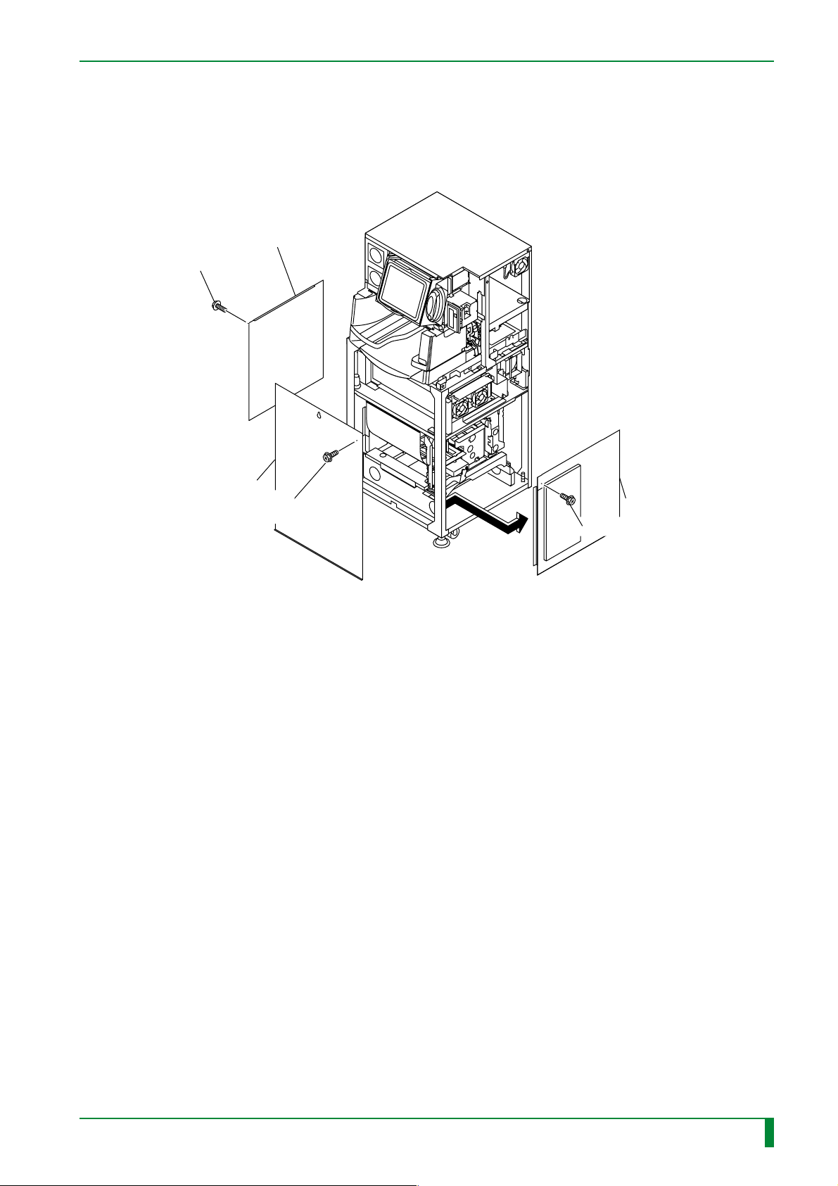
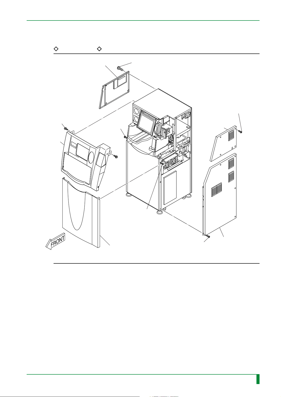
3. Removing and Installing the Covers
FR7H3000.EPS
■ Removal procedure
Upper left-hand side cover
[Remove]
T4x12 (x4)
Upper rear cover
MC - 8
[Remove]
T4x12 (x4)
[Remove]
T4x12 (x6)
T4x6 (x3)
Lower left-hand side cover
Upper front cover
Lower front cover
[Remove]
BR4x8 (x2)
[Loosen] T4x12 (x2)
[Loosen] T4x12 (x2)
[Remove]
T4x12 (x8)
Lower rear cover
[Remove]
T4x6 (x4)
Upper right-hand
side cover
[Remove]
T4x6 (x7)
Lower right-hand side cover
009-058-00
10.20.2000 FM2732 (2)
CR-IR347
Service Manual
FR7H3098.EPS
MC - 8
Page 16
Left-hand inner cover
[Remove]
BR4x8 (x6)
MC - 9
Light protect plate
[Remove]
BR4x8 (x9)
■ Installation procedure
Accomplish installation by reversing the removal procedure.
Right-hand inner cover
[Remove] BR4x8 (x5)
FR7H3099.EPS
009-058-01
009-058-00
05.15.2001 FM3052
10.20.2000 FM2732 (2)
CR-IR347
Service Manual
MC - 9
Page 17

MC - 10
4. Removing and Installing the Cassette Set Unit
4.1 Cassette Set Unit
FR7H3001*.EPS
■ Removal procedure
(1) Pull out the tray.
“4.5 Pulling Out the Tray”
009-058-00
10.20.2000 FM2732 (2)
CR-IR347
Service Manual
MC - 10
Page 18

MC - 11
E
(2) Remove the cassette set unit.
◆
NOTE
Before removing the cassette set unit, place the removal arm in the following position:
◆
#1
[Rotate] Timing belt
IP removal unit
IP removal arm
#2
[Remove] BR4x8 (x3)
Cassette set unit
Cassette
FR7H3315.
set unit
■ Installation procedure
Accomplish installation by reversing the removal procedure.
009-058-00
10.20.2000 FM2732 (2)
CR-IR347
Service Manual
Positioning screw
FR7H3315.EPS
MC - 11
Page 19

FR7H3301.EPS
Shutter assembly
[Remove] BR4x8 (x2)
Cassette set unit
Shutter
4.2 Shutter
■ Removal procedure
(1) Remove the following covers:
• Upper right-hand side cover
• Upper left-hand side cover
MC - 12
FR7H3002.EPS
• Upper front cover
“3. Removing and Installing the Covers”
(2) Remove the front shelf cover.
“4.5 Pulling Out the Tray”
(3) Remove the shutter assembly.
009-058-00
10.20.2000 FM2732 (2)
CR-IR347
Service Manual
MC - 12
Page 20
(4) Remove the shutter.
MC - 13
Bracket
[Remove]
B3x6
Bracket
Torsion
coil spring
Bearing
Shutter
Bracket
Bearing
■ Installation procedure
◆
NOTE
When installing the shutter, ensure that gap A shown above permits the entry of a single
thickness of a 150 mm scale but does not permit the entry of a single thickness of a 300
mm scale.
To accomplish installation, reverse the removal procedure.
◆
Shutter
A
[Remove]
Hook
FR7H3302.EPS
009-058-00
10.20.2000 FM2732 (2)
CR-IR347
Service Manual
MC - 13
Page 21

4.3 Cassette Ejection Sensor (SK1)
FR7H3003.EPS
■ Removal procedure
(1) Remove the following covers:
• Upper right-hand side cover
• Upper left-hand side cover
MC - 14
• Upper front cover
“3. Removing and Installing the Covers”
(2) Remove the front shelf cover.
“4.5 Pulling Out the Tray”
009-058-00
10.20.2000 FM2732 (2)
CR-IR347
Service Manual
MC - 14
Page 22
FR7H3304.EPS
Shutter assembly
(4) #2
[Remove]
Q4x12 (x2)
(Loktite)
(3)
[Remove] BR4x8 (x2)
Cassette set unit
(4) #1
[Disconnect] Connector (SK1)
Bracket
(4) #3
[Remove] SK1
(3) Remove the shutter assembly.
(4) Remove the cassette ejection sensor (SK1).
MC - 15
■ Installation procedure
To accomplish installation, reverse the removal procedure.
009-058-00
10.20.2000 FM2732 (2)
CR-IR347
Service Manual
MC - 15
Page 23

4.4 Barcode Reader (BCRK1)
FR7H3004.EPS
■ Removal procedure
(1) Remove the following covers:
• Lower front cover
• Lower right-hand side cover
“3. Removing and Installing the Covers”
MC - 16
009-058-00
10.20.2000 FM2732 (2)
CR-IR347
Service Manual
MC - 16
Page 24

(2) Remove the barcode reader (BCRK1).
MC - 17
Cassette set unit
#1
[Disconnect] Connector
BCRK1
Bracket
#2
[Remove]
BR4x8 (x2)
#4
[Remove]
N2x6 (x2)
#3
[Cut] Tie (x2)
FR7H3306.EPS
009-058-00
10.20.2000 FM2732 (2)
CR-IR347
Service Manual
MC - 17
Page 25

■ Installation procedure
◆
NOTE
When clamping the cable with a tie, ensure that the cable does not come out of the
bracket.
Bracket
◆
MC - 18
Cable
Tie
Cable
OK
To accomplish installation, reverse the removal procedure.
NG
FR7H3307.EPS
009-058-00
10.20.2000 FM2732 (2)
CR-IR347
Service Manual
MC - 18
Page 26

BLANK PAGE
MC - 19
009-058-00
10.20.2000 FM2732 (2)
CR-IR347
Service Manual
MC - 19
Page 27

4.5 Pulling Out the Tray
FR7H3005.EPS
■ Pull-out procedure
(1) Remove the following covers:
• Upper left-hand side cover
• Upper right-hand side cover
MC - 20
• Upper front cover
• Lower front cover
• Lower right-hand side cover
“3. Removing and Installing the Covers”
009-058-00
10.20.2000 FM2732 (2)
CR-IR347
Service Manual
MC - 20
Page 28
REFERENCE
MC - 21
Upper left-hand side cover
[Remove]
BR4x8 (x2)
Upper front cover
#4
#3
[Loosen]
T4x12 (x2)
#1
[Remove] T4x12 (x4)
#2
[Remove]
T4x6 (x4)
Upper right-
hand side cover
[Loosen]
T4x12 (x2)
Lower front cover
#5
#6
[Remove] T4x6 (x7)
Lower right-hand
side cover
FR7H3308.EPS
009-058-00
10.20.2000 FM2732 (2)
CR-IR347
Service Manual
MC - 21
Page 29

(2) Disconnect the connectors.
MC - 22
[Disconnect] Connectors
IP removal unit
CNL2
CNL3
CNL1
FRONT
[Disconnect] Connectors
Cassette set unit
CNU1
CNK1
CNK2
CNSOLK1
BCR08A CN1
FR7H3309.EPS
009-058-00
10.20.2000 FM2732 (2)
CR-IR347
Service Manual
MC - 22
Page 30

(3) Pull out the tray.
#1 [Loosen] BR4x8 (x2)
#2 [Remove] BR4x8 (x2), W6
[Remove] BR4x8 (x2)
MC - 23
Bracket
#3
FRONT
#4
[Pull out] Tray
FR7H3389.EPS
009-058-00
10.20.2000 FM2732 (2)
CR-IR347
Service Manual
MC - 23
Page 31

(4) Remove the front shelf cover.
#1
[Remove] Screw cover
#2
[Remove] T4x6 (x2)
Stack table
MC - 24
#3
[Remove]
BR4x8 (x2)
Front shelf cover
#4
[Remove] BR4x8 (x4)
FR7H3373.EPS
009-058-00
10.20.2000 FM2732 (2)
CR-IR347
Service Manual
MC - 24
Page 32

■ Push-in procedure
◆
NOTE
During reinstallation of the front shelf cover, align the cassette insertion face of the front shelf
cover to the guide protrusion of the cassette set unit.
If they are not aligned, a cassette hold failure may result.
◆
MC - 25
Front shelf cover
■ Check
A
CHECK
#1 [Temporarily Tighten]
BR4x8 (x4)
#3 [Temporarily Tighten]
For push-in, reverse the pull-out procedures.
DETAIL A
#2 [Align]
Cassette set unit
Front shelf
cover
Cassette insertion face
Protrusion
Guide
FR7H3391.EPS
Power ON the machine and make sure that a cassette hold failure does not occur when a
cassette is inserted.
009-058-00
009-058-02
10.20.2000 FM2732 (2)
08.30.2001 FM3142
CR-IR347
Service Manual
MC - 25
Page 33

4.6 Cassette Hold Solenoid (SOLK1)
FR7H3006.EPS
■ Removal procedure
(1) Pull out the tray.
“4.5 Pulling Out the Tray”
(2) Remove the shutter assembly.
MC - 26
Shutter
Shutter assembly
Cassette set unit
[Remove] BR4x8 (x2)
FR7H3374.EPS
009-058-00
10.20.2000 FM2732 (2)
CR-IR347
Service Manual
MC - 26
Page 34

(3) Remove the cassette hold solenoid (SOLK1).
A
#1
[Cut] Tie (x2)
MC - 27
#2
[Disconnect]
Connector
(CN-SOLK1)
DETAIL A
CHECK
Cassette hold
solenoid
Arm
#3
[Remove] B3x6 (x3)
009-058-00
10.20.2000 FM2732 (2)
CR-IR347
Service Manual
FR7H3310.EPS
MC - 27
Page 35

■ Installation procedure
(1) Temporarily retain the cassette hold solenoid.
◆
NOTE
◆
Before temporarily retain the cassette hold solenoid, attach the hold pin to the arm. After
the cassette hold solenoid is temporarily retained, you cannot attach the hold pin to the
arm.
FRONT
#2
[Loosely attach]
B3x6 (x3)
Hold pin
MC - 28
Arm
#1
[Hook]
Cassette hold
solenoid
Cassette hold solenoid
FR7H3312.EPS
009-058-00
10.20.2000 FM2732 (2)
CR-IR347
Service Manual
MC - 28
Page 36

(2) Set the jig so that its protrusion goes into the hole in the guide plate.
#1
[Lift] Rubber roller
#2
[Set] Jig
Jig
MC - 29
Hold pin
Protrusion
FR7H3375.EPS
009-058-00
10.20.2000 FM2732 (2)
CR-IR347
Service Manual
MC - 29
Page 37

(3) Adjust the cassette hold solenoid mounting position.
Jig
MC - 30
(4) Remove the jig.
#3
[Loosen] BR3x6 (x3)
#1
[Remove]
Extension spring
#4
[Engage]
#2
[Push up]
Cassette hold solenoid
FR7H3313.EPS
009-058-00
10.20.2000 FM2732 (2)
CR-IR347
Service Manual
MC - 30
Page 38

■ Check procedure
(1) Check that the cassette hold solenoid is in the following state:
● Normal condition
The hold pin end must be raised above the guide plate by the action of the extension
spring.
● When the lever is lowered
The hold pin end must not be positioned above the guide plate.
MC - 31
Guide plate
[Lower] Lever
Hold pin
Extension spring
Guide plate
Hold pin
Lever loweredNormal
FR7H3314.EPS
◆
If the hold pin is positioned above the guide plate when the lever is lowered, the cassette
is damaged when it is inserted into position.
(2) Complete installation by reversing the removal procedure.
009-058-00
10.20.2000 FM2732 (2)
NOTE
◆
CR-IR347
Service Manual
MC - 31
Page 39

4.7 Cassette Hold Sensor (SK3)
FR7H3007.EPS
■ Removal procedure
(1) Remove the cassette set unit.
“4.1 Cassette Set Unit”
(2) Remove the shutter assembly.
MC - 32
Shutter assembly
Cassette set unit
[Remove] BR4x8 (x2)
FR7H3316.EPS
009-058-00
10.20.2000 FM2732 (2)
CR-IR347
Service Manual
MC - 32
Page 40

(3) Remove the cassette hold sensor (SK3).
Cassette set unit
T
O
P
#3
SK3
MC - 33
#2
Connector
[Remove] B3x6
■ Installation procedure
◆
NOTE
When mounting the bracket, secure it by aligning it with the dowel and pressing it upward.
◆
Bracket
Bracket
#1
FR7H3317.EPS
009-058-03
08.30.2002 FM3476
Protrusion
FR7H3382.EPS
Accomplish installation by reversing the removal procedure.
CR-IR347
Service Manual
MC - 33
Page 41

4.8 Claw Guide Assembly
FR7H3008.EPS
■ Removal procedure
(1) Remove the cassette set unit.
“4.1 Cassette Set Unit”
(2) Remove the shutter assembly.
MC - 34
Shutter assembly
Cassette set unit
[Remove] BR4x8 (x2)
FR7H3359.EPS
009-058-00
10.20.2000 FM2732 (2)
CR-IR347
Service Manual
MC - 34
Page 42

MC - 35
◆
NOTE
◆
When you remove the claw guide assembly, hold it down to prevent the compression coil
spring from popping out.
(3) Remove the claw guide assembly.
CHECK
Dowel
Cable
Edge saddle
[Disconnect] Connector (SK3)
Bracket
#1
[Remove]
BR4x8 (x2)
#2
Claw guide assembly
Compression
spring
(L = 31 mm)
Dowel
#4
[Remove] Q4x12 (x2)
(Loktite)
#3
[Remove] BR4x8 (x2)
Cassette set unit
009-058-00
10.20.2000 FM2732 (2)
CR-IR347
FRONT
T
O
P
Service Manual
FR7H3318.EPS
MC - 35
Page 43

■ Installation procedure
◆
NOTE
• When installing the claw guide assembly, adjust the degree of guide plate parallelism
with the mounting screws (BR4x8, x2) loosened.
For parallelism adjustment purposes, apply a 300 mm scale to the guide plate trailing
end (toward the IP removal unit) and measure the gap between the scale and guide
plate.
◆
0.5 mm or greater gap = NG
Gap smaller than 0.5 mm = OK
MC - 36
300 mm scale
Less than 0.5 mm
Guide plate
FRONT
300 mm scale
FR7H3320.EPS
009-058-00
10.20.2000 FM2732 (2)
CR-IR347
Service Manual
MC - 36
Page 44

MC - 37
◆
NOTES
• When applying Loktite to a guide screw, apply it to the portion of the guide screw on the
bracket side. Do not bring Loktite into contact with the guide.
◆
Shaft
B3x10 (x2)
(Loktite)
SK3
Bearing
A
Guide
Spacer
Bearing
Bracket
B3x6 (x2)
Bracket
DETAIL A
Loktite
Guide
B3x10
Bracket
FR7H3319.EPS
• When installing the SK3 bracket, align it with the dowels and secure it while pressing
the protrusion upward.
Bracket
Protrusion
FR7H3382.EPS
To accomplish installation, reverse the removal procedure.
009-058-03
08.30.2002 FM3476
CR-IR347
Service Manual
MC - 37
Page 45

■ Check procedure
• Insert a cassette into the cassette set unit to check that the stopper pin opens the
cassette cover. If the cassette cover does not open, adjust the parallelism of the
installed guide plate.
[Insert] Cassette
MC - 38
A
DETAIL A
Stopper
Pin
Cassette
Cover
• Make sure that the coil spring inside the claw guide assembly is engaged with the
009-058-00
10.20.2000 FM2732 (2)
dowels.
CR-IR347
Service Manual
FR7H3390.EPS
MC - 38
Page 46

BLANK PAGE
MC - 39
009-058-00
10.20.2000 FM2732 (2)
CR-IR347
Service Manual
MC - 39
Page 47

4.9 Cassette IN Sensor (SK2)
FR7H3009.EPS
■ Removal procedure
(1) Remove the cassette set unit.
“4.1 Cassette Set Unit”
(2) Remove the shutter assembly.
MC - 40
Shutter
Shutter assembly
Cassette set unit
[Remove] BR4x8 (x2)
FR7H3377.EPS
009-058-00
10.20.2000 FM2732 (2)
CR-IR347
Service Manual
MC - 40
Page 48

(3) Disconnect the connector (SK2).
MC - 41
DETAIL A
O
A
Bracket
#1
[Remove]
BR4x8 (x2)
[Disconnect]
#2
Cable
Edge saddle
T
P
SK2
#3
[Disconnect]
Connector (SK2)
FR7H3323.EPS
009-058-00
10.20.2000 FM2732 (2)
CR-IR347
Service Manual
MC - 41
Page 49

(4) Remove the cassette IN sensor (SK2).
MC - 42
Cassette set unit
#1
[Remove] BR4x8
#2
[Cut] Tie
CHECK
#3
[Remove]
B2x10 (x2)
SK2
Bracket
FR7H3322.EPS
009-058-00
10.20.2000 FM2732 (2)
CR-IR347
Service Manual
MC - 42
Page 50

■ Installation/adjustment procedure
◆
INSTRUCTION
The SK2 must be positioned so that the actuator does not interfere with the cut in the
stopper.
◆
MC - 43
DETAIL A
Stopper
Cut
in stopper
Actuator
A
SK2
OK NG
FR7H3324.EPS
009-058-00
10.20.2000 FM2732 (2)
CR-IR347
Service Manual
MC - 43
Page 51

(1) Mount the SK2 on the bracket.
MC - 44
Actuator
◆
NOTE
#2
[Attach] Tie
SK2
Bracket
◆
#1
[Attach]
B2x10 (x2)
FR7H3325.EPS
When mounting the SK2 assembly, do not allow the actuator to come into contact with
neighboring parts and bend. If the actuator is bent, it does not normally function.
REFERENCE
Ensure that the SK2 connector cable does not come into contact with the IP removal unit.
SK2
009-058-00
10.20.2000 FM2732 (2)
Approx.
10 mm
FR7H3386.EPS
CR-IR347
Service Manual
MC - 44
Page 52

(2) Loosely attach the SK2 assembly.
MC - 45
Stopper
DETAIL A
A
Dowel
SK2
SK2 assembly
[Loosely attach] BR4x8
Actuator
Cassette set unit
SK2
FR7H3326.EPS
009-058-00
10.20.2000 FM2732 (2)
CR-IR347
Service Manual
MC - 45
Page 53

(3) Connect the SK2 connector.
◆
NOTE
◆
Make sure that the connector cable is not positioned outside the bracket.
DETAIL A
MC - 46
T
O
P
A
Bracket
#3
[Attach] BR4x8 (x2)
#2
[Attach] Cable
Edge saddle
SK2
#1
[Connect]
Connector (for SK2)
(4) To complete installation, reverse the removal procedure.
FR7H3378.EPS
009-058-00
10.20.2000 FM2732 (2)
CR-IR347
Service Manual
MC - 46
Page 54

■ Check procedure
(1) Turn ON the power.
(2) Start the M-Utility.
(3) Perform SK2 operational checkout.
#1 [Input/ENT]
#2 [Input/ENT]
0. QUIT
1. ERROR LOG UTILITY
2. CONFIGURATION SETTING
3. TEST MODE
4. ELECTRICAL UTILITY
5. SCANNER UTILITY
6. MECHANICAL UTILITY
7. FILE UTILITY
8. BACKUP MEMORY
9. HV OFF
10. MENU SETTING
11.SYSTEM UTILIT
> 6
0. QUIT
1. MOTOR
2. ACTUATOR
3. SENSOR
4. UNIT
MU > 3
Y
MC - 47
0. QUIT
1. NUMBER
2. MONITOR
3. MONITOR ALL
#3 [Input/ENT]
MU : SEN > 3
REFERENCE
For SK2 operational checkout, perform the following steps:
1. Insert a cassette all the way into the cassette set unit.
→
Check that the SK2 closes.
2. Try to pull the cassette while it is locked with the hold pin.
→
Check that the SK2 remains closed.
3. Remove the cassette.
→
Check that the SK2 opens.
FR7H3330.EPS
009-058-00
10.20.2000 FM2732 (2)
CR-IR347
Service Manual
MC - 47
Page 55

(4) Verify the SK2 assembly mounting position.
MC - 48
150 mm scale
DETAIL B
SK2
A
Actuator
SK2
DETAIL A
[Check]
SK2
SK2
The SK2 should be OFF
when this gap is about 1.0 mm.
B
Guide plate
Scale
Scale
Guide plate
009-058-00
10.20.2000 FM2732 (2)
CR-IR347
Service Manual
SK2
The SK2 should be ON
when this gap is about 1.5 mm.
FR7H3379.EPS
MC - 48
Page 56

MC - 49
(5) Press the actuator with a scale or the like to check that the actuator does not interfere
with the cut in the stopper.
DETAIL A
Stopper
Cut
in stopper
Actuator
A
(6) Exit the M-Utility.
(7) Turn OFF the power.
SK2
GOOD NG
FR7H3328.EPS
009-058-00
10.20.2000 FM2732 (2)
CR-IR347
Service Manual
MC - 49
Page 57

4.10 Rubber Roller
FR7H3011.EPS
■ Removal procedure
(1) Remove the cassette set unit.
“4.1 Cassette Set Unit”
MC - 50
009-058-00
10.20.2000 FM2732 (2)
CR-IR347
Service Manual
MC - 50
Page 58

FR7H3333.EPS
#2
[Remove]
Extension spring
L = 117 mm
Housing
Roller bearing
#1
[Remove]
Extension spring
L = 104 mm
Housing
Roller
bearing
Cassette set unit
Rubber roller
CHECK
(2) Remove the rubber roller.
MC - 51
■ Installation procedure
■ Check procedure
009-058-00
10.20.2000 FM2732 (2)
◆
INSTRUCTION
◆
The extension spring size varies with the mounting location. Pay due attention to the
extension spring mounting location.
To accomplish installation, reverse the removal procedure.
Check that the rubber roller is not installed with right and left reversed.
CR-IR347
Service Manual
MC - 51
Page 59

4.11 Guide Plate
■ Removal procedure
(1) Remove the rubber roller.
“4.10 Rubber Roller”
MC - 52
FR7H3012.EPS
009-058-00
10.20.2000 FM2732 (2)
CR-IR347
Service Manual
MC - 52
Page 60

(2) Remove the shutter assembly.
(3) Remove the sensor assembly (SK2).
MC - 53
Shutter assembly
Cassette set unit
(2)
[Remove]
BR4x8 (x2)
(3)
[Remove]
BR4x8
SK2
assembly
FR7H3334.EPS
009-058-00
10.20.2000 FM2732 (2)
CR-IR347
Service Manual
MC - 53
Page 61

(4) Disconnect the SK2 connector.
MC - 54
Bracket
A
T
O
P
#3
[Disconnect] Connector
#1
[Remove]
BR4x8 (x2)
DETAIL A
#2
[Disconnect]
Cable
Edge saddle
SK2
Connector (for SK2)
FR7H3380.EPS
009-058-00
10.20.2000 FM2732 (2)
CR-IR347
Service Manual
MC - 54
Page 62

MC - 55
FR7H3335.EPS
Guide A
Guide A
#1
[Remove] BR4x8
#2
[Remove] BR4x8
#8
[Remove] BR4x8
#9
[Remove] BQ4x10
Stopper B
#3
[Remove]
BR4x8 (x2)
Guide B
Bracket
Guide B
Stopper B
#7
[Remove]
BQ4x10
Stopper A
Stopper A
Cassette set unit
FRONT
#4
[Remove] BR4x12
#6
[Remove] BR4x8
#5
[Remove] BR4x8
(Guide plate
retaining screw)
(5) Remove the guides and stoppers.
REFERENCE
Stopper A is secured by a dowel on a side plate. To remove stopper A, it is necessary to
remove the guide plate retaining screw.
009-058-00
10.20.2000 FM2732 (2)
CR-IR347
Service Manual
MC - 55
Page 63

(6) Remove the guide plate.
Guide plate
FRONT
Hold pin
MC - 56
[Remove]
BR4x8 (x5)
Compression
spring
Guide
plate
FR7H3336.EPS
REFERENCE
Removing the guide plate separates the compression spring from the hold pin.
009-058-00
10.20.2000 FM2732 (2)
CR-IR347
Service Manual
MC - 56
Page 64

FR7H3337.EPS
Cassette set unit
Hold pin
■ Installation procedure
◆
INSTRUCTION
When installing the guide plate, mount the hold pin on the arm.
MC - 57
◆
REFERENCE
When installing stoppers A and B, verify their mounting positions. Note that stoppers A
and B differ in shape.
Stopper A Stopper B
FR7H3338.EPS
009-058-00
10.20.2000 FM2732 (2)
CR-IR347
Service Manual
MC - 57
Page 65

(1) Loosely attach the guide plate.
Guide plate
FRONT
Hold pin
MC - 58
[Loosely attach] BR4x8 (x5)
Guide
plate
FR7H3339.EPS
009-058-00
10.20.2000 FM2732 (2)
CR-IR347
Service Manual
MC - 58
Page 66

(2) Install the guides and stoppers.
MC - 59
Guide A
Guide A
[Attach]
BR4x8 (x2)
[Remove] BQ4x10
#1
FRONT
#2
Guide B
Guide B
#4
[Attach] BR4x12
Bracket
#3
[Attach]
BR4x8 (x2)
Cassette set unit
Stopper A
#5
[Attach] BR4x8
[Attach] BR4x8
#6
Stopper A
#7
[Attach] BQ4x10
Stopper B
Stopper B
#8
[Attach] BR4x8
#9
[Attach] BQ4x10
FR7H3340.EPS
009-058-00
10.20.2000 FM2732 (2)
CR-IR347
Service Manual
MC - 59
Page 67

MC - 60
(3) While measuring the levelness of the guide plate with a 300 mm scale or the like,
tighten the remaining four guide plate retaining screws.
300 mm scale
[Tighten] BR4x8 (x4)
FR7H3341.EPS
009-058-00
10.20.2000 FM2732 (2)
CR-IR347
Service Manual
MC - 60
Page 68

MC - 61
◆
NOTE
For parallelism adjustment purposes, apply a 300 mm scale to the guide plate trailing end
(toward the IP removal unit) and measure the gap between the scale and guide plate.
◆
0.5 mm or greater gap = NG
Gap smaller than 0.5 mm = OK
Guide plate
300 mm scale
300 mm scale
Less than 0.5 mm
FRONT
FR7H3342.EPS
(4) Complete installation by reversing the removal procedure.
◆
NOTE
◆
When installing the SK2 assembly, perform its specified adjustment procedure.
“4.9 Cassette IN Sensor (SK2)”
009-058-00
10.20.2000 FM2732 (2)
CR-IR347
Service Manual
MC - 61
Page 69

■ Check procedure
Insert a cassette into the cassette set unit to check that the stopper pin opens the cassette
cover. If the cassette cover does not open, adjust the parallelism of the guide plate.
[Insert] Cassette
DETAIL A
MC - 62
A
Stopper
Pin
Cassette
Cover
009-058-00
10.20.2000 FM2732 (2)
CR-IR347
Service Manual
FR7H3381.EPS
MC - 62
Page 70

BLANK PAGE
MC - 63
009-058-00
10.20.2000 FM2732 (2)
CR-IR347
Service Manual
MC - 63
Page 71

4.12 Guide Stoppers
FR7H3013.EPS
■ Removal procedure
(1) Remove the cassette set unit.
“4.1 Cassette Set Unit”
(2) Remove the rubber roller.
“4.10 Rubber Roller”
MC - 64
(3) Remove the guide stoppers.
A
SW3
Guide stopper
#1
[Remove] Q3x12
Guide
#2
[Remove] S3x10
(Loktite)
#3
[Remove] Q3x12
SW3
009-058-00
10.20.2000 FM2732 (2)
CR-IR347
Service Manual
A
FR7H3343.EPS
MC - 64
Page 72

MC - 65
Guide
#8
[Remove] S3x10
(Loktite)
#9
[Remove] Q3x12
Guide stopper
B
Guide
Guide
#4
[Remove] Q3x12
SW3
#5
[Remove] S3x10
(Loktite)
#6
[Remove] Q3x12
SW3
Guide stopper
C
#7
[Remove] Q3x12
SW3
SW3
■ Installation procedure
To accomplish installation, reverse the removal procedure.
009-058-00
10.20.2000 FM2732 (2)
CR-IR347
B
Service Manual
C
FR7H3388.EPS
MC - 65
Page 73

4.13 Movable Guides
FR7H3014.EPS
■ Removal procedure
(1) Remove the guide plate.
“4.11 Guide Plate”
(2) Remove the guide stoppers.
MC - 66
“4.12 Guide Stoppers”
(3) Remove the movable guides.
FRONT
T
O
P
Movable guide (right)
Movable guide (left)
#1
[Remove] Q4x8 (x2)
#2
[Remove] Q4x8 (x2)
009-058-00
10.20.2000 FM2732 (2)
CR-IR347
Service Manual
FR7H3344.EPS
MC - 66
Page 74

Movable guide
MC - 67
Compression spring
(L = 43 mm)
Movable guide
Compression spring
(L = 43 mm)
Bracket
#3
[Remove] BR4x8
FR7H3345.EPS
■ Installation procedure
However, complete the following adjustment procedure immediately before shutter assembly
reinstallation.
009-058-00
10.20.2000 FM2732 (2)
CR-IR347
Service Manual
MC - 67
Page 75

■ Adjustment procedure
● Widthwise adjustment
(1) Loosen the movable guide retaining screws.
(2) Tighten the retaining screws so that the bracket pin lodges in the movable guide hole.
MC - 68
Pin
(1)
[Loosen] Q4x8 (x2)
(2)
[Tighten]
Hole
Pin
(1)
[Loosen] Q4x8 (x2)
(2)
[Tighten]
Hole
FR7H3387.EPS
009-058-00
10.20.2000 FM2732 (2)
CR-IR347
Service Manual
MC - 68
Page 76

● Movable guide rearward adjustment
❍ Metric guide
(1) Loosen the bracket.
(2) Adjust the bracket position to meet the following requirements:
• The up-down movement of the movable guide front end must be smooth.
• The amount of movable guide rear end descent must not exceed 1 mm.
A
B
DETAIL A
MC - 69
DETAIL B
FRONT
Metric guide
Bracket
(1)
[Loosen] BQ4x10
(1)
[Loosen] BQ4x10
Front end check
The movement must be smooth.
(2)
[Adjust] Bracket
F
R
O
N
T
009-058-00
10.20.2000 FM2732 (2)
Rear end check
CR-IR347
Service Manual
1 mm max.
FR7H3347.EPS
MC - 69
Page 77

❍ Inch guide
(1) Loosen the bracket.
(2) Adjust the bracket position to meet the following requirements:
• The up-down movement of the movable guide front end must be smooth.
• The amount of movable guide rear end descent must not exceed 1 mm.
A
B
DETAIL A
Inch guide
MC - 70
DETAIL B
FRONT
(2)
[Adjust] Bracket
(1)
[Loosen] BQ4x10
Front end check
The movement must be smooth.
Rear end check
F
R
O
N
T
009-058-00
10.20.2000 FM2732 (2)
CR-IR347
Service Manual
1 mm max.
FR7H3348.EPS
MC - 70
Page 78

❍ 20 x 30 mammography guide
(1) Loosen the bracket.
(2) Adjust the bracket position to meet the following requirements:
• The up-down movement of the movable guide front end must be smooth.
• The amount of movable guide rear end descent must not exceed 1 mm.
A
B
DETAIL A
24 x 30 mammography guide
MC - 71
(1)
[Loosen] BR4x8
DETAIL B
FRONT
Front end check
The movement must be smooth.
Rear end check
(2)
[Adjust] Bracket
F
R
O
N
T
009-058-00
10.20.2000 FM2732 (2)
CR-IR347
Service Manual
1 mm max.
FR7H3349.EPS
MC - 71
Page 79

■ Check procedure
Insert cassettes of various sizes into the cassette set unit to check that the cassettes open.
If the cassettes do not open, perform the adjustment procedures again.
MC - 72
009-058-00
10.20.2000 FM2732 (2)
CR-IR347
Service Manual
MC - 72
Page 80

BLANK PAGE
MC - 73
009-058-00
10.20.2000 FM2732 (2)
CR-IR347
Service Manual
MC - 73
Page 81

MC - 74
5. Removing and Installing the IP Removal Unit
5.1 IP Removal Unit
FR7H3015.EPS
■ Removal procedure
(1) Remove the cassette set unit.
“4.1 Cassette Set Unit”
(2) Remove the following cover:
• Lower left-hand side cover
“3. Removing and Installing the Covers”
009-058-00
10.20.2000 FM2732 (2)
CR-IR347
Service Manual
MC - 74
Page 82

(3) Remove the IP removal unit.
MC - 75
CHECK
IP removal unit
[Remove] BR4x8 (x4)
FR7H3236.EPS
009-058-00
10.20.2000 FM2732 (2)
CR-IR347
Service Manual
MC - 75
Page 83

■ Installation procedure
To accomplish installation, reverse the removal procedure.
◆
NOTE
When installing the IP removal unit, loosely attach it with the screws, and shift it rearward
and then rightward (toward the reference surface).
◆
MC - 76
IP removal unit
FR7H3237.EPS
009-058-00
10.20.2000 FM2732 (2)
CR-IR347
Service Manual
MC - 76
Page 84

BLANK PAGE
MC - 77
009-058-00
10.20.2000 FM2732 (2)
CR-IR347
Service Manual
MC - 77
Page 85

5.2 IP Leak Valve (SVL1)
FR7H3016.EPS
■ Removal procedure
(1) Remove the following cover:
• Lower rear cover
“3. Removing and Installing the Covers”
MC - 78
009-058-00
10.20.2000 FM2732 (2)
CR-IR347
Service Manual
MC - 78
Page 86

(2) Remove the IP leak valve (SVL1)
[Disconnect]
Connector
#5
[Disconnect] Hose
#4
[Cut] Tie
SVL1
MC - 79
#3
#2
[Cut] Tie
Bracket
#1
[Remove] BR4x8 (x4)
#6
[Remove] BR4x8 (x2)
IP removal unit
■ Installation procedure
To accomplish installation, reverse the removal procedure.
009-058-00
10.20.2000 FM2732 (2)
CR-IR347
Service Manual
FR7H3201.EPS
MC - 79
Page 87

5.3 Suction Cup HP Sensor (SL1)
FR7H3017.EPS
■ Removal procedure
(1) Remove the following covers:
• Lower front cover
• Lower right-hand side cover
MC - 80
“3. Removing and Installing the Covers”
(2) Rotate the timing belt to move the actuator away from the SL1.
FRONT
IP removal unit
IP removal arm
Actuator
Timing belt
009-058-00
10.20.2000 FM2732 (2)
CR-IR347
Service Manual
SL1
FR7H3202.EPS
MC - 80
Page 88

(3) Remove the suction cup HP sensor (SL1).
#1
[Disconnect]
Connector
MC - 81
#3
[Remove] SL1
#2
[Remove] B3x6 (x2)
Bracket
009-058-00
10.20.2000 FM2732 (2)
CR-IR347
Service Manual
FR7H3203.EPS
MC - 81
Page 89

■ Installation procedure
(1) Mount the suction cup HP sensor (SL1) on the bracket.
(2) Loosely attach the bracket.
(3) Secure the bracket so that the SL1 end face is flush with the actuator end face when
the distance between the side plate end face and roller bearing end face is 95.0 mm.
MC - 82
Side plate
FRONT
95.0 mm
Roller bearing
End face
Actuator
IP removal unit
Actuator
end face
SL1 end face
SL1 end face
Actuator
end face
Roller bearing
IP removal arm
SL1
Bracket
OK NG
FR7H3204.EPS
(4) Install the IP removal unit and cassette set unit by reversing their removal procedures.
009-058-00
10.20.2000 FM2732 (2)
CR-IR347
Service Manual
MC - 82
Page 90

■ Check/adjustment procedure
CAUTION
When turning ON the machine with the laser protective housing (cover installed over the
scanner unit) removed, be sure to turn OFF the high-voltage switch (S1) on the SCN board
(1) Turn ON the power.
(2) Start the M-Utility.
(3) Place the IP removal arm in the HP.
0. QUIT
1. ERROR LOG UTILITY
2. CONFIGURATION SETTING
3. TEST MODE
4. ELECTRICAL UTILITY
5. SCANNER UTILITY
6. MECHANICAL UTILITY
7. FILE UTILITY
8. BACKUP MEMORY
9. HV OFF
10. MENU SETTING
#1 [Input/ENT]
11.SYSTEM UTILIT
> 6
Y
MC - 83
#2 [Input/ENT]
#3 [Input/ENT]
#4 [Input/ENT]
0. QUIT
1. INITIALIZE
2. MOTOR
3. ACTUATOR
4. SENSOR
5. UNIT
MU > 5
0. QUIT
1. IP FEED/LOAD UNIT
2. UP-DOWN UNIT
3. SIDE-POSITIONING GRIP
4. SIDE-POSITIONING UNIT
5. AFTER-READING GRIP
6. DRIVING GRIP
7. DRIVEN GRIP
8. MIRROR UP/DOWN
9. CLEANING GUIDE
MU : UNI > 1
0. QUIT
1. ARM HOME POSITION
2. FEED/LOAD
MU : UNI : IFL > 1
009-058-00
10.20.2000 FM2732 (2)
CR-IR347
Service Manual
FR7H3205.EPS
MC - 83
Page 91

MC - 84
(4) Verify that the distance between the end faces of the IP removal unit side plate and
roller bearing is about 95.0 mm.
Side plate
95.0 mm
FRONT
IP removal unit
Roller bearing
Roller bearing
IP removal arm
FR7H3206.EPS
009-058-00
10.20.2000 FM2732 (2)
CR-IR347
Service Manual
MC - 84
Page 92

BLANK PAGE
MC - 85
009-058-00
10.20.2000 FM2732 (2)
CR-IR347
Service Manual
MC - 85
Page 93

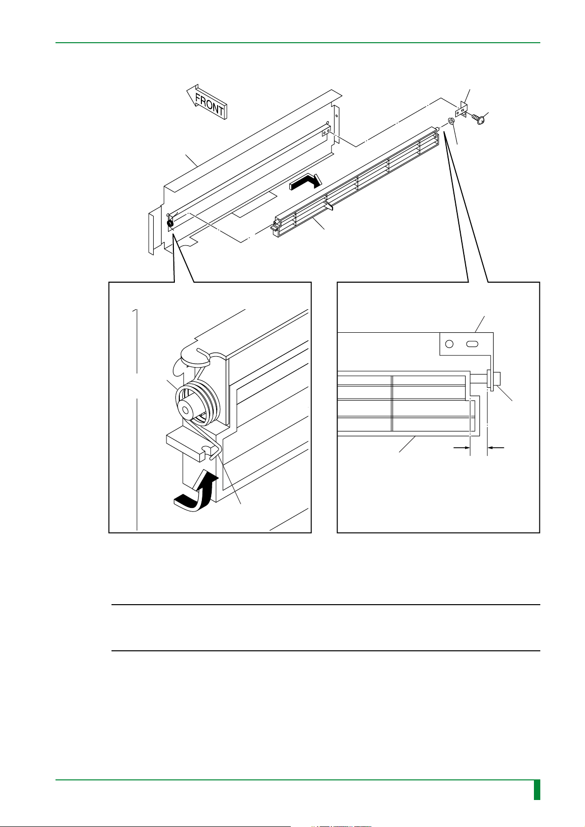
5.4 Timing Belt (for IP Conveyance)
FR7H3019.EPS
■ Removal procedure
(1) Remove the following covers:
• Lower front cover
• Lower right-hand side cover
MC - 86
“3. Removing and Installing the Covers”
009-058-00
10.20.2000 FM2732 (2)
CR-IR347
Service Manual
MC - 86
Page 94

(2) Remove the timing belt (for IP conveyance).
[Disconnect] Connector
#2
#1
[Remove] BR4x8 (x2)
MC - 87
Fan
FRONT
FRONT
CHECK
Timing belt
Shaft
Timing belt pulley
Roller bearing
#3
[Remove] BR4x30
Roller bearing
FR7H3207.EPS
009-058-00
10.20.2000 FM2732 (2)
CR-IR347
Service Manual
MC - 87
Page 95

■ Installation procedure
To accomplish installation, reverse the removal procedure.
■ Check/adjustment procedure
• Verify that the timing belt is properly threaded through its path.
• After the timing belt is replaced with a new one or the tensioner is removed and reinstalled,
remove the IP removal unit and adjust the belt tension with the tensioner screw.
“5.1 IP Removal Unit”
Scales
361 mm
MC - 88
Push-pull gauge
560.5 N
Timing belt
FRONT
FR7H3208.EPS
009-058-00
10.20.2000 FM2732 (2)
CR-IR347
Service Manual
MC - 88
Page 96

BLANK PAGE
MC - 89
009-058-00
10.20.2000 FM2732 (2)
CR-IR347
Service Manual
MC - 89
Page 97

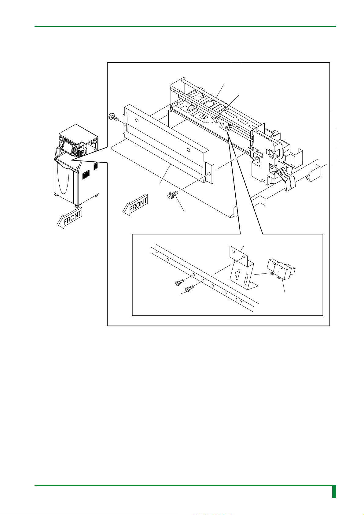
5.5 Guide Plate A
MC - 90
Guide plate A
■ Removal procedure
(1) Remove the following covers:
• Lower front cover
• Lower right-hand side cover
• Lower left-hand side cover
• Lower rear cover
“3. Removing and Installing the Covers”
FR7H3020.EPS
FR7H3209.EPS
009-058-00
10.20.2000 FM2732 (2)
CR-IR347
Service Manual
MC - 90
Page 98

(2) Remove the fan assembly.
(3) Remove guide plate A.
MC - 91
Fan
#2
[Disconnect] Connector
#1
[Remove] BR4x8 (x2)
Bracket
Anti-static
member
#4
[Remove] B3x6 (x6)
#3
[Remove] BR4x8
#5
[Disconnect]
Connector
A
#6
[Remove]
A3x6 (x2)
CHECK
■ Installation procedure
To accomplish installation, reverse the removal procedure.
■ Check procedure
Make sure that the anti-static member is brought into contact with the roller.
009-058-02
009-058-00
08.30.2001 FM3142
10.20.2000 FM2732 (2)
Guide plate A
CR-IR347
Service Manual
FR7H3210.EPS
MC - 91
Page 99

5.6 Rubber Rollers C and D
IP removal unit
FR7H3021.EPS
■ Removal procedure
(1) Remove the timing belt (for IP conveyance).
“5.4 Timing Belt (for IP Conveyance)”
FRONT
Rubber roller C
MC - 92
Rubber roller D
FR7H3211.EPS
(2) Remove guide plate A.
“5.5 Guide Plate A”
009-058-00
10.20.2000 FM2732 (2)
CR-IR347
Service Manual
MC - 92
Page 100

FR7H3212.EPS
FRONT
FRONT
#3
[Remove] E6
Timing belt pulley
Rubber roller D
#4
[Remove]
Extension spring
(L = 92 mm)
Roller bearing
Roller bearing
Housing
Housing
Rubber roller C
#2
[Remove] Extension spring (L = 80 mm)
#1
[Remove] Gear (x2)
Anti-static member
CHECK
(3) Remove rubber rollers C and D.
MC - 93
■ Installation procedure
◆
INSTRUCTION
◆
The extension spring size varies with the mounting location. When installing the
extension springs, pay due attention to their mounting locations.
To accomplish installation, reverse the removal procedure.
■ Check procedure
Make sure that the anti-static member is brought into contact with the roller.
009-058-02
009-058-00
08.30.2001 FM3142
10.20.2000 FM2732 (2)
CR-IR347
Service Manual
MC - 93
 Loading...