

Page 1

Operating Instructions Edition 08/2004
FIDAMAT 6
Gas analyzer for the measurement
of total hydrocarbons
7MB2421
gas analysis
Page 2

1
Page 3

s
FIDAMAT 6
Gas analyzer for the measurement of
total hydrocarbons
Operating instructions
A5E00222135-01
Release 08/2004
Page 4

The reproduction, transmission or use of this document or its
contents is not permitted without express written authority.
Offenders will be liable for damages. All rights created by the
granting of patents or registration of a design are reserved.
Technical data subject to change without notice.
Weitergabe sowie Vervielfältigung dieser Unterlage,
Verwertung und Mitteilung ihres Inhaltes nicht gestattet, soweit
nicht ausdrücklich zugestanden.
Zuwiderhandlungen verpflichten zu Schadenersatz. Alle
Rechte vorbehalten, insbesondere für den Fall der
Patenterteilung oder GM-Eintragung.
Technische Änderungen vorbehalten.
Toute communication ou reproduction de ce document, toute
exploitation ou communication de son contenu sont interdites,
sauf autorisation expresse.
Tout manquement à cette règle est illicite et expose son auteur
au versement de dommages et intérêts. Tours nos droits sont
réservés pour le cas de la délivrance d'un brevet ou celui de
l'enregistrement d'un modèle d'utilité.
Modifications techniques sont réservées.
La divulgación y reproducción de este documento asi como el
aprovechamiento de su contenido, no están autorizados, a no
ser que se obtenga el consentimiento expreso, para ello.
Los infractores quedan obligados a la indemnización por
daños y perjucios. Se reservan todos los derechos, en
particular para el caso de concesion de Patente o de Modelo
de Utilidad.
Salvo modificaciones ténicas.
ULTRAMAT, OXYMAT, CALOMAT, SIPAN
sono marchi registrati di S
IEMENS AG.
Le denominazioni di altri prodotti menzionati in questa
documentazione possono essere marchi il cui uso da parte di
terzi può violare i diritti di proprietà.
Conformemente alla "Legge sulle unità di misura" i dati in
pollici valgono soltanto per l'esportazione.
La trasmissione a terzi e la riproduzione di questa
documentazione, cosiccome lo sfruttamento del suo contenuto
non è permesso, se non autorizzato per iscritto.
Le infrazioni comporteranno una richiesta di danni. Tutti i diritti
sono riservati, in particolare nel caso di brevetti. Modifiche
tecniche possibili.
ULTRAMAT, OXYMAT, CALOMAT, SIPAN
son marcas registradas de S
IEMENS AG.
Las otras designaciones que figuran en este documento
puenden ser marcas cuya utilización por terceros para sus
propios fines puede violar los derechos de los proprietarios de
dichas marcas.
Conforma a la "Ley sobre las unidades de medida", las
dimensiones en pulgadas sólo son válidas para la exportación.
ULTRAMAT, OXYMAT, CALOMAT, SIPAN
sont des marques déposées de S
IEMENS AG.
D'autres dénominations utilisées dans ce document peuvent
également être des marques déposées dont l'utilisation par
des tiers à leurs propres fins peut enfreindre les droits des
propriétaires desdites marques.
ULTRAMAT, OXYMAT, CALOMAT, SIPAN
sind Marken der S
IEMENS AG.
Die übrigen Bezeichnungen in diesem Handbuch können
Marken sein, deren Benutzung durch Dritte für deren Zwecke
die Rechte der Inhaber verletzen können.
Die Angaben in Zoll (inch) gelten gemäß dem Gesetz über
Einheiten im Meßwesen" nur für den Export.
ULTRAMAT, OXYMAT, CALOMAT, SIPAN
are S
IEMENS registered trademarks.
A
ll other product or system names are (registered) trademarks
of their respective owners and must be treated accordingly.
A
ccording to the German law on units in measuring
technology, data in inches only apply to devices for export.
SIEMENS AG
A
utomation and Drives
Process Instrumentation
D-76181 Karlsruhe
Siemens Aktiengesellschaft
© Siemens AG 2004
Subject to modifications without prior notice
Order no. A5E00222135
Printed in Germany
A
G 0804 En 0.05 118 PU
Page 5

Table of contents
1. INFORMATION FOR THE OWNER ..................................................................................................... 1-1
1.1
INFORMATION FOR OUR CUSTOMERS ............................................................................................. 1-2
1.2 GENERAL COMMENTS................................................................................................................... 1-2
1.3 USING THIS MANUAL ..................................................................................................................... 1-3
1.4 HAZARD INFORMATION ................................................................................................................. 1-3
1.5 USE FOR THE PURPOSE INTENDED ................................................................................................ 1-4
1.6 QUALIFIED PERSONNEL ................................................................................................................ 1-5
1.7 WARRANTY INFORMATION............................................................................................................. 1-5
1.8 DELIVERY INFORMATION ............................................................................................................... 1-6
1.9 STANDARDS AND REGULATIONS .................................................................................................... 1-6
1.10 DECLARATION OF CONFORMITY..................................................................................................... 1-7
2. TECHNICAL DESCRIPTION ............................................................................................................. 2-1
2.1
SCOPE OF APPLICATION ............................................................................................................... 2-2
2.2 DESIGN ....................................................................................................................................... 2-4
2.3 MODE OF OPERATION ................................................................................................................... 2-7
2.4 COMMUNICATIONS ..................................................................................................................... 2-10
2.5 TECHNICAL DATA........................................................................................................................ 2-14
3. INSTALLATION INSTRUCTIONS ....................................................................................................... 3-1
3.1
SAFETY INSTRUCTIONS................................................................................................................. 3-2
3.2 GENERAL INSTALLATION REQUIREMENTS ....................................................................................... 3-3
3.3 GAS CONDITIONING ...................................................................................................................... 3-5
3.4 ELECTRICAL CONNECTIONS .......................................................................................................... 3-6
3.4.1 POWER SUPPLY....................................................................................................................... 3-6
3.4.2 CONNECTING THE SIGNAL LINES ............................................................................................... 3-6
3.4.3 CIRCUIT DIAGRAMS (ELECTRICAL CONNECTIONS)....................................................................... 3-8
3.5 DIMENSION DRAWINGS ............................................................................................................... 3-11
4. START-UP.................................................................................................................................... 4-1
4.1
SAFETY INSTRUCTIONS................................................................................................................. 4-2
4.2 START-UP PREPARATIONS ............................................................................................................ 4-3
4.3 START-UP AND OPERATION........................................................................................................... 4-5
4.3.1 MEASURING RANGES ............................................................................................................... 4-5
4.3.2 CALIBRATION........................................................................................................................... 4-7
5. OPERATION ................................................................................................................................. 5-1
5.1
GENERAL COMMENTS................................................................................................................... 5-2
5.2 STATUS DIAGRAM......................................................................................................................... 5-7
5.3 OVERVIEW OF OPERATOR FUNCTIONS ........................................................................................... 5-9
5.3.1 DIAGNOSIS............................................................................................................................ 5-10
5.3.2 CALIBRATION......................................................................................................................... 5-11
5.3.3 MEASURING RANGES ............................................................................................................. 5-17
5.3.4 PARAMETERS ........................................................................................................................ 5-20
5.3.5 CONFIGURATION.................................................................................................................... 5-27
Page 6

6. MAINTENANCE ............................................................................................................................. 6-1
6.1
MAINTENANCE CONCEPT .............................................................................................................. 6-2
6.1.1 PUMP MAINTENANCE................................................................................................................ 6-2
6.1.2 REPLACING THE FILTER PLATE.................................................................................................. 6-2
6.2 REPLACING THE MOTHERBOARD AND OPTION BOARD ..................................................................... 6-3
6.3 CHANGING FUSES ........................................................................................................................ 6-3
6.4 CLEANING THE UNIT ..................................................................................................................... 6-4
6.5 MAINTENANCE REQUEST AND FAULT MESSAGE .............................................................................. 6-4
6.5.1 LIST OF MAINTENANCE REQUESTS ............................................................................................ 6-5
6.5.2 FAULTS................................................................................................................................... 6-7
6.5.3 OTHER FAULTS........................................................................................................................ 6-8
7. LIST OF SPARE PARTS AND RETURNS............................................................................................ 7-1
7.1
INFORMATION ON ORDERING ......................................................................................................... 7-2
7.2 LIST OF SPARE PARTS .................................................................................................................. 7-3
7.3 RETURNS .................................................................................................................................. 7-12
7.4 ABBREVIATIONS ......................................................................................................................... 7-15
7.5 OVERVIEW OF OPERATOR FUNCTIONS ......................................................................................... 7-16
Page 7

1-1
1. Information for the owner
1.1. Information for our customers
1.2. General comments
1.3. Using this manual
1.4. Hazard information
1.5. Use for the purpose intended
1.6. Qualified personnel
1.7. Warranty information
1.8. Delivery information
1.9. Standards and regulations
1.10. Declaration of conformity
Page 8

Information for the owner
FIDAMAT 6 gas analyzer
1-2 Operating manual – A5E00222135-01
1.1 Information for our customers
Please read this manual carefully before beginning operation of the
sensor! It will provide you with important information and data you need to
ensure proper functioning of the sensor and reduce maintenance costs.
Following these instructions will help you to operate the device more
easily and efficiently, allowing you to achieve reliable measuring results.
1.2 General comments
Before product described in this manual left the factory, it was inspected
and found to be in perfect condition as regards safety. To keep it in this
state and to ensure its safe and problem-free operation the product
should only be used in the manner described by the manufacturer. In
addition, proper transportation, storage and installation as well as careful
operation and maintenance of the product are vital for ensuring correct
and safe operation.
This manual provides the information you will need for using the
described product for the purpose for which it is intended.
The manual is intended to be used for technically qualified personnel with
special training or who have relevant knowledge in the field of automation
technology (instrumentation and control technology).
Familiarity with and a technically faultless implementation of the safety
information (including warnings) contained in this manual is essential for
hazard-free installation and commissioning as also for safe operation and
maintenance of the product described. Only qualified personnel possess
the special knowledge required not only for a correct interpretation in the
individual concrete case of the safety information and warnings provided
in this manual for general application but also for putting them into
practice.
This manual is a permanent part of the scope of supply even when
ordering it separately has been permitted for logistical reasons.
Due to the sheer number of technical details it is not possible to cover all
versions of the product described nor every conceivable aspect of
installation, operation, maintenance and use of the product as part of a
system. If you require further information, or should problems be
encountered which are not treated in sufficient depth in this document,
contact your local Siemens representative for the information you require.
Note
Particularly before the device is used for new applications in the area of
research and development, we recommend you contact us to discuss the
application in question.
Page 9

Information for the owner
FIDAMAT 6 gas analyzer
Operating manual – A5E00222135-01 1-3
1.3 Using this manual
This manual provides you with information on using, installing,
operating, and maintaining this device.
Pay particular attention to all warnings and notes. Information of this
type is set apart from the rest of the text and specially identified by
appropriate symbols (see examples on the left). This information
provides you with useful tips on how to avoid operating the analyzer
incorrectly.
1.4 Hazard information
Please observe the following notes not only for your own personal safety
but also to safeguard against damage to the product described as well as
any devices connected to it.
Safety information and warnings are given particular emphasis in this
manual by means of the various "signal” terms defined below. They apply
to both users and maintenance personnel and are intended to help
prevent dangers to life and limb, or to health, and also to prevent damage
to property. These notes are also marked by warning symbols which
reflect the meaning of the accompanying text and may therefore vary
from the examples given below. Within the context of this manual and
information on the product itself, the terms used are defined as follows:
Danger
means that death or severe injury and / or considerable damage
to property will result if the corresponding precautions are not taken.
Warning
means that death or severe injury and / or considerable damage to
property could occur if the corresponding precautions are not taken.
Caution
with a warning triangle means that minor injury may result if the
corresponding precautions are not taken.
Caution
without a warning triangle means that damage to property may result if
the corresponding precautions are not taken.
Page 10

Information for the owner
FIDAMAT 6 gas analyzer
1-4 Operating manual – A5E00222135-01
Attention
means that an undesirable event or condition may result if the note in
question is not observed.
Note
gives important information about the product, about using the
product, or about the corresponding part of the manual to which
special attention is to be drawn.
1.5 Use for the purpose intended
In this manual 'use for the purpose intended' means that this product may
only be used for the application cases described in the catalog and in the
technical description (in this regard see also "Technical description” from
page 2-1 onwards) and only in conjunction with third-party devices and
components recommended or approved by Siemens.
The product described in this manual has been designed, manufactured,
inspected and documented in compliance with the relevant safety
standards. For this reason, provided both the handling requirements
described for planning, installation, operation and maintenance and also
safety instructions are observed, under normal circumstances the unit will
not be a source of danger with respect to personal health and safety nor
with respect to damage to property. The analyzer has been designed in
such a way that a safe separation between primary and secondary
circuits is ensured. Extra-low voltages which are connected must also be
generated by safe separation.
Warning
Once the housing or shock-hazard protection has been removed or the
system cabinet opened, certain parts or components of this unit or
system which could be carrying a hazardous voltage become accessible.
For this reason only appropriately qualified personnel should be
permitted such access to this unit. These persons must have a thorough
knowledge of all sources of danger and of maintenance activities as
described in this operating manual.
Page 11

Information for the owner
FIDAMAT 6 gas analyzer
Operating manual – A5E00222135-01 1-5
1.6 Qualified personnel
Unqualified tampering with the unit or system, or failure to observe the
warnings in the manual or affixed to the unit or system cabinet could
result in severe bodily injury and / or damage to property. Only
appropriately qualified personnel should therefore be permitted such
access to this unit or system.
Within the context of the safety information in this manual or on the
product itself, qualified personnel is defined as persons who:
• as planning and design personnel are familiar with the safety
concepts applicable in automation technology, or
• as operating personnel have been given instruction on working
with automation technology equipment and who are familiar with
the operation-related content of this manual, or
• as commissioning or maintenance personnel possess the
training which enables them to repair automation technology
equipment of this kind or who have been authorized to operate,
ground or label devices, systems and electrical circuits in
accordance with accepted technical safety standards.
1.7 Warranty information
Your attention is expressly directed to the fact that the nature and quality
of the product is described exclusively and conclusively in the contract of
purchase. The contents of this product documentation do not constitute
part of a past or existing agreement, promise, or legal relationship nor are
they intended to modify these. All obligations on the part of Siemens
originate from the purchase contract in question, which also includes the
full and exclusively valid warranty provisions. The contractual provisions
relating to liability for defects are neither extended nor in any way
restricted by the information contained in the present document.
Page 12

Information for the owner
FIDAMAT 6 gas analyzer
1-6 Operating manual – A5E00222135-01
1.8 Delivery information
The scope of supply corresponding to the applicable purchase contract is
shown in the shipping documents enclosed with the consignment.
When opening the packaging, read and comply with the instructions
provided on the packaging material. Make sure the consignment is
complete and undamaged. In particular, you should also, if applicable,
check the order number on the nameplates against the ordering
information.
If possible, you should not discard the packaging material as this could be
needed later should anything need to be returned. A returns form is
provided on page 7-14 of the section entitled "Spare parts and returns.”
1.9 Standards and regulations
As far as possible the specifications and manufacture of this device were
based on the harmonized European standards. Where harmonized
European standards were not applied, the standards and regulations of
the Federal Republic of Germany will apply (see also "Technical data” on
page 2-14).
If this product is used outside the area of validity of these standards and
regulations, the standards and regulations valid in the owner's country
should be observed.
Page 13

Information for the owner
FIDAMAT 6 gas analyzer
Operating manual – A5E00222135-01 1-7
1.10 Declaration of conformity
Product name, model
FIDAMAT 6E
7MB2421-xxxxx-xxxx
7MB2427-xxxxx-xxxx
is in compliance with the following standard(s) or documents:
- Low-Voltage Equipment Directives (73/23/EEC and 93/68/EEC)
- EMC Directives (89/336/EEC, 91/263/EEC, 92/31/EEC, 93/68/EEC and 93/97/EEC)
- Harmonized standards applied to
all devices EN 61326
EN 61010
In accordance with the aforementioned EC directives, the EC
Declarations of Conformity are kept available for the relevant
authorities by
Siemens Aktiengesellschaft
Automation and Drives
A&D PI 2
D-76181 Karlsruhe
If this product is used outside the European Union, the standards and regulations valid in the
owner's country must be observed.
Page 14

Information for the owner
FIDAMAT 6 gas analyzer
1-8 Operating manual – A5E00222135-01
Page 15

2. Technical description
2.1. Scope of application
2.2. Design
2.3. Mode of operation
2.4. Communications
2.5. Technical data
Page 16

Technical description
FIDAMAT 6 gas analyzer
2-2 Operating manual – A5E00222135-01
2.1 Scope of application
The FIDAMAT 6 gas analyzer is used for the
quantitative determination of hydrocarbons. The
analyzer is also suitable for measurements in
corrosive and condensing gas mixtures.
The measuring principle is based on flame
ionization detection (FID) with a minimum
detection level of about 0.1 ppm. During
combustion of hydrocarbons in a hydrogen flame,
ions are produced which are in turn converted into
a current flow by application of an electrical field.
The current intensity arising from this is a
measure of the number of carbon atoms.
Benefits
The FIDAMAT 6 gas analyzer stands out due to
its very wide scope of application.
Accordingly, measurement is possible:
• With H
2
O vapor concentrations up to
100%
• With ultrapure gas applications
• With high-boiling components (up to
200°C)
• When corrosive gases are present
Unlike other comparable devices, the FIDAMAT 6
has:
• A very low transverse gas sensitivity
compared to unwanted gasses
• Low consumption of combustion air
• Low susceptibility to being affected by
oxygen
The device is also equipped with warning and fault
messages, for example:
• Failure of combustion gas supply
• Detector flame extinguished
• Malfunctions of pump and filter
• and so on
Examples of applications
• Environmental protection
• Wastewater (in combination with a
stripping unit, determination of
hydrocarbon content of liquids)
• Measurement in flue gases in accordance
with Emissions Prevention Directives and
Clean Air Guidelines (13. BlmSchV /
17. BlmSchV and TA-Luft) for these types
of fuel: oil, coals, gases and refuse (with
TÜV [Technical Inspectorate] approval)
• Monitoring at workplaces with respect to
maximum allowable concentration of
pollutants
• Quality surveillance
• Process 14
• Ultrapure-gas measurement in media
such as O2, CO2, inert gases and cold
measurement gases
• Measurement of corrosive and
condensing gases
• Process optimization
• Automotive industry (engine
development, vehicle assembly
development and certification)
• Measurement of emissions
(environmental protection)
Locations
• Chemical plants
• Gas manufacturers (quality surveillance
for ultrapure gases)
• Research and development
• Cement industry
• Paint shops and chemical cleaning
facilities
• Refineries (tank farms, wastewater)
• Drying plants
• Solvent recovery facilities
• Pharmaceutical industry
Page 17

Technical description
FIDAMAT 6 gas analyzer
Operating manual –A5E00222135-01 2-3
Main features
• Four measuring ranges freely
parametrizable, also with suppressed
zero point, all ranges linear
• Hydrogen required: H2
• Extremely short measuring spans
• Electrically isolated measured-value
output 0/ 2/ 4 to 20 mA (negated also)
• Automatic or manual range changeover
selectable; remote changeover is also
possible
• Measured values can be retained during
calibration
• Time constants selectable within wide
limits (static / dynamic noise
suppression); in other words, the Unit's
response time can be adjusted to suit the
measurement task on hand
• Simple to use due to menu-controlled
operation
• User operation based on NAMUR
recommendations
• Short response time
• Low long-term drift
• Three operator control levels each with
own authorization code to prevent
inadvertent or unauthorized operator
actions
• External pressure pick-ups can be
connected to correct process gas
pressure fluctuations
• Units easy to swap over since electrical
connections only need to be
disconnected from unit
• Wear-free, corrosion-resistant filter
• No clogging of measuring-gas capillary
since a quartz capillary is used
• Low consumption of combustion air
• Digital display of gas concentration, of
measuring gas, combustion air and
hydrogen pressure
• Response factors meet the minimum
requirements of the Clean Air Guidelines
and of the German Automotive Industry
Working Group
• Simplicity of operation due to a numerical
membrane keyboard and operator
guidance
• Parametrizable automatic measuring
range calibration
• PROFIBUS (DP/ -PA) / AK
• Menu and interface are compatible with
the other Series 6 devices (CALOMAT 6,
OXYMAT 6, ULTRAMAT 6, OXYMAT 61)
• Customer-specific versions of the device,
such as:
- Customer acceptance
- TAG plates
- Drift recording
Page 18

Technical description
FIDAMAT 6 gas analyzer
2-4 Operating manual – A5E00222135-01
2.2 Design
Design of the overall unit
The FIDAMAT 6 consists of two main modules.
a) Analysis module
b) Electronics
a) Analyzer section
This consists of a oven in which the following
components are installed:
- Measuring gas filter (heated)
- Flame ionization detector (FID)
- Various restrictors
- Two pressure regulators
- Two pressure sensors
- Solenoid valves
- Bulkhead connections 6 mm or ¼"?
The unit has been designed in such a way that
interior parts are easily accessible for
maintenance. Access is possible both from the top
(for maintenance of individual parts) and from the
rear (for replacing the measuring-gas filter).
The measuring-gas pump is easily accessible
from above. Both the gas connections and the
electrical connections are located on the rear of
the unit.
b) Electronics module
This consists of:
- Operator control board with display
- Motherboard
- Adapter board
- Option boards: PROFIBUS (DP/ PA), AK,
AUTOCAL
The operator control board is integrated into the
front panel. The adapter board accommodates the
preamplifier for measured data acquisition and for
the control unit.
Design of the FIDAMAT 6 housing
• 19" rack module with 4 HU for installation
in swing frame
• 19" rack module with 4 HU for installation
in cabinets, with telescopic or support
rails
• Front panel for maintenance access,
swings downwards (for example, for
laptop connection, RS 485)
Gas path Material
Piping
Gas entry
Seals
Measuring-gas
restrictor
Reactant-gas
restrictors
Pump diaphragm
Pump head
Stainless steel 1.4571
Stainless steel 1.4571
Graphite
Quartz
Stainless steel 1.4571
PTFE
Stainless steel 1.4571
Detector
Nozzle
FID housing
Quartz
Stainless steel 1.4571
• Gas connections for measuring-gas entry
(sample) and measuring-gas outlet
(exhaust) and also hydrogen and
combustion air; pipe diameter 6 mm or ¼"
(Swagelok)
Page 19

Technical description
FIDAMAT 6 gas analyzer
Operating manual –A5E00222135-01 2-5
Display and control panel
• Large LCD panel for simultaneous display
of:
- Measured value (digital and analog
display)
- Measuring ranges
- Status bar
• LCD panel contrast adjustable via menu
• Permanent LCD backlighting
• Five-digit measured-value display
(decimal point counts as a digit)
• Wipe-clean diaphragm keyboard and front
panel
• Menu-guided operation for
parametrization, test functions and
calibration
• User guidance in plain text
• Graphic display of concentration curve;
time intervals can be parametrized
• User software in two languages in each
case:
German/English;
English/Spanish;
French/English;
Spanish/English;
Italian/English
Inputs and outputs
• Two analog inputs can be configured
• One analog output 0/ 2/ 4 - 20 mA
• Six binary inputs can be configured as
required
for example, for measuring range
changeover, processing of external
signals from sample preparation
• Six relay outputs can be configured as
required for example, for faults,
maintenance request, limit value alarm,
external solenoid valves
• Further eight binary inputs and relay
outputs can be added in each case for
automatic calibration with a maximum of
four calibration gases
Communications
• ELAN (RS 485) contained in base unit
(connection at rear)
Options
• AK interface for the automotive industry
with expanded functions
• Converter to RS 232 (for ELAN)
• Converter to TCP/IP Ethernet (for ELAN)
• Incorporation in networks via
PROFIBUS DP/PA interface
• SIPROM GA software as service and
maintenance utility (for ELAN)
Response factors
Substance Response factors
n-butane 1,00
n-propane 1,00
n-heptane 1,00
Cyclohexane 1,08
Isopropanol 0,81
Toluene 1,06
Acetone 0,92
Ethyl acetate 0,76
Isobutyl acetate 0,83
Methane 1,06
Ethane 0,99
n-hexane 1,01
Isooctane 1,04
Acetylene 0,91
Propene 0,84
Methanol 0,87
Ethanol 0,83
Acetic acid 1,13
Methyl acetate 0,67
Benzole 1,01
Ethyl benzole 0,96
p-xylene 1,03
Dichloromethane 1,13
Trichloroethene 1,01
Tetrachloroethene 1,07
Chloroform 0,72
Chlorobenzene 1,15
Page 20

Technical description
FIDAMAT 6 gas analyzer
2-6 Operating manual –A5E00222135-01
Fig. 2-1: Membrane keyboard and graphics display
Fig. 2-1: Membrane keyboard and graphics display
Page 21

Technical description
FIDAMAT 6 gas analyzer
Operating manual – A5E00222135-01 2-7
Fig. 2-2: FIDAMAT 6 – Mode of operation
2.3 Mode of operation
The FIDAMAT 6 measures compound-class-specifically not
component-specifically. It measures the total of all organic carbons in
a measuring gas but giving different weighting to the hydrocarbon
molecules.
As a first approximation, the value displayed is proportional to the
number of C atoms in the molecule in question. In practice, however,
there are deviations from this. The reading deviation for the molecule
in question is expressed by the response factor.
The measuring gas is supplied to the FIDAMAT 6 under overpressure
or drawn in by the built-in diaphragm pump (optionally via a heated
line and an additional filter) and then routed to the flame ionization
detector via a non-clogging fused-silica restrictor. Within the detector
the hydrocarbons contained in the measuring gas are combusted in
an oxy-hydrogen flame. During the combustion process the organic
hydrocarbons are ionized.
Page 22

Technical description
The ions which are released are converted into an ion current by the
polarization voltage between two electrodes and then measured using
a highly sensitive amplifier.
The current measured is proportional to the number of organic C
atoms of the hydrocarbons in the measuring gas.
A pressure regulator keeps the pressure of the hydrogen constant. A
mutually adjusted system of pump, capillaries and combustion-air
pressure regulator ensures a constant measuring-gas pressure.
After switching on the analyzer, the flame will be ignited as soon as a
flame temperature of 165°C has been reached. The pump is started
automatically once the flame reaches a temperature of 220°C.
The FIDAMAT 6 sends out various signals in the form of floating
contacts:
• Maintenance request
Measuring-gas flow rate (filter / pump)
Fan failure (advance warning for measurement accuracy)
The unit continues to measure as normal and the measured value is
not affected.
• Fault
Hydrogen, combustion air and measuring gas pressure, temperature,
physical section and pump, fault in the electronics (temperature).
The measured value can be affected; under certain circumstances the
unit will switch into a different state (the combustion-gas valve is
closed). See also "List of maintenance requests” on page 6-5.
Note
Sample gases must be free of dust when they enter the analyzers.
Condensate should be avoided. For this reason, it will in most
application cases be necessary to use a gas conditioning device
suitable for the measurement task in question.
2-8 Operating manual – A5E00222135-01
FIDAMAT 6 gas analyzer
Page 23
Technical description
FIDAMAT 6 gas analyzer
Operating manual – A5E00222135-01 2-9
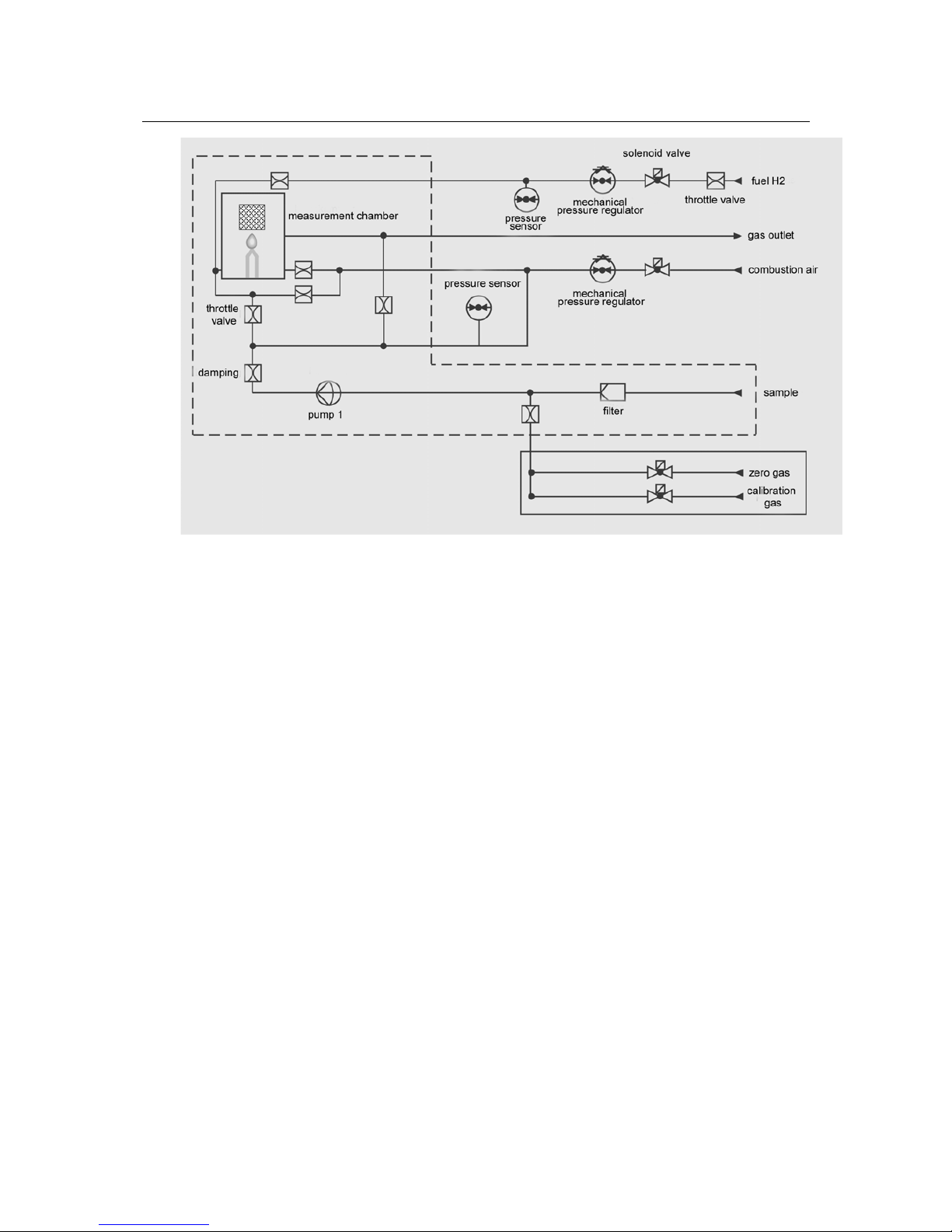
Fig. 2-3: Gas circuit (unit with pump)
Page 24

Technical description
FIDAMAT 6 gas analyzer
2-10 Operating manual – A5E00222135-01
2.4 Communications
All of the gas analyzers in Series 6, ULTRAMAT
6, OXYMAT 6/ 61, CALOMAT 6, ULTRAMAT 23
and also FIDAMAT 6 provide the following
communication methods:
• ELAN interface (also with SIPROM GA)
• PROFIBUS DP / PA
• AK interface
ELAN interface
ELAN is a serial interface (RS 485) built in as
standard and which allows communication
between several analyzers. A maximum of 12
analyzers with no more than four components
may be networked together. Connection can be
made even without a PC.
The following diagram shows how this works.
Fig. 2-4: Typical arrangement for an ELAN network
(RS 232)
No. Key
1 Computer
2
RS-485 / RS-232 converter with
RS 485 and RS 232 connecting leads
3 RS 485 bus plug with jumper
4 Analyzer
5 RS 485 cable
6 RS 485 bus plugs
7 RS 485 network
8 9-pole SUB D connector
9 Optional: RS-485 repeater
Interface parameters
Level RS 485
Baud rate 9600
Data bit 8
Stop bit 1
Start bit 1
Parity None
No information feedback
Ordering information Order no.
Interface description
C79000-B5200-C176
RS 485-RS 232 converter
C79451-Z1589-U1
SIMATIC cable / bus cable
6XV1 830-OEH10
SIMATIC bus plugs
6ES7 972-OBB11-OXAO
9-pole SUB D connector
6ES7 972-OBB11-OXAO
Repeater
6ES7 972-OAA01-OXAO
For further information, see the ELAN interface
description.
Order number:
C79000-B5200-C176 German
C79000-B5274-C176 English
Page 25

Technical description
FIDAMAT 6 gas analyzer
Operating manual –A5E00222135-01
2-11
SIPROM GA
SIPROM GA is a software utility especially for
service and maintenance tasks. It allows remote
operation and monitoring of all functions of the
analyzers, either as individual units or networked
together.
Functions:
• Display and storage of all device data
• Remote operation of all device functions
• Parameter and configuration settings
• Comprehensive diagnostics information
• Remote calibration
• On-line help
• Cyclic saving of measured values
• Status on hard disk and exportation to
user programs available on the market
• Downloading of new software
Hardware requirements:
• PC or laptop, Pentium 133 MHz,
RAM 32 MB, CD drive
• At least 10 MB free on hard disk
• VGA graphics card supported by
Windows
• Printer supported by Windows
• Unused COM port: RS 232 or for
connection to ELAN network RS 485 /
RS 232
•
For connecting the Ethernet / RS 485
interface converter, a standard 10 Mbit
or 100 Mbit network (RJ 45 connection)
with TCP/ IP is required. With an RS 485
network the distance must not be greater
than 500 m or a repeater will need to be
installed.
Software requirements (optional):
• Windows 95
• Windows 98
• Windows NT 4.0
• Windows 2000
• Windows XP
Ordering information Order no.
SIPROM GA software,
German or English selectable
at time of installation,
consisting of 1 CD with
installation instructions,
software, product certificate
and registration form
S79610-B4014-A1
Firmware retrofit kit for older
analyzers:
FIDAMAT 6
- German
- English
- French
- Spanish
- Italian
A5E00223093
A5E00223146
A5E00223149
A5E00223152
A5E00223155
PROFIBUS DP / PA
PROFIBUS DP / PA is the field-bus market leader.
All Siemens gas analyzers when equipped with an
optional plug-in board (can be retrofitted) have
Profibus capability and meet the mandatory "device
profile for analysis devices” defined by the PNO
(PROFIBUS Nutzer Organisation) (Profibus users
organization). Centralized access to the analyzers
installed in the system is possible using the
SIMATIC PDM operator control utility.
The term "field bus” designates a digital
communication system with which decentrally
installed field devices in a system are networked
together using a single cable and at the same
time connected to automation devices or to a
process control system.
Due to its high transmission speeds coupled with
relatively small data volumes for each device, the
PROFIBUS DP variant is used widely in
production automation, while PROFIBUS PA
takes particular account of properties demanded
in process control, such as large quantities of
data and deployment in explosion-hazard areas.
The benefits to the user lie is considerable
potential for savings in all parts of the system,
from engineering and commissioning, to
operation and maintenance, and later on to
installation expansion.
Page 26

Technical description
FIDAMAT 6 gas analyzer
2-12 Operating manual – A5E00222135-01
The gas analyzers can be operated from a
control system or a separate PC using the
SIMATIC PDM (Process Device Manager)
operator control utility, a program which runs
under Windows XP or Windows 2000 and which
can also be incorporated into the SIMATIC PCS
7 process control system. This means that is
possible to represent in a clear and logical
manner not only the incorporation of the devices
in the system but also the complex parametrical
structure of the analyzers and operating the units
becomes simply a matter of clicking.
The PROFIBUS users organization (PNO) is an
independent international body representing the
interests of a large number of manufacturers and
users. Alongside services such as giving advice,
training and the certification of devices, its
primary duty is the further development,
standardization and promotion of PROFIBUS
technology. Definition of a mandatory
functionality for a class of devices in a profile is a
necessary condition for devices from different
manufactures behaving in a uniform manner –
what is known as "interoperability”. At the end of
1999 a mandatory profile for analysis devices
was established down thereby ensuring that all
devices in a system with PROFIBUS capability
will work together.
This profile defines the functionalities of the analysis
devices in a block model. For example, the device
block (physical block) describes the measurement
procedure, the analyzer and manufacturer names,
serial number and operational state (in operation,
under maintenance). Different functional blocks
contain the execution of specific functions such as
measured-value processing and alarm response. The
transducer blocks describe the functionality of the
measurement procedure itself as well as control of
the procedure – for example, preprocessing of a
measured value, cross-corrections, curves,
measuring ranges and also switching and control
operations. Data transmission between bus users is
defined in protocols.
Here a distinction is drawn between cyclic and
acyclic services. Time-critical data, such as
measured values and states, are transmitted
using cyclic services. Acyclic services, on the
other hand, permit device parameters to be
interrogated or modified during operation.
All of the gas analyzers in Series 6 (ULTRAMAT
6, OXYMAT 6/ 61, CALOMAT 6, ULTRAMAT 6
and FIDAMAT 6 and also ULTRAMAT 23) have
PROFIBUS capability once fitted with an optional
plug-in board (which can also be retrofitted) (see
also the electronics spare parts from page 7-3
onward of the spare parts list).
Fig. 2-5: Typical layout of a PROFIBUS system
Page 27
Technical description
FIDAMAT 6 gas analyzer
Operating manual –A5E00222135-01
2-13
AK interface
AK is an interface which is not a standard
integrated part of Series 6 gas analyzers but
which can only be used when an additional board
is fitted. It can be ordered under this order
number:
C79451-A3474-B61
Unlike PROFIBUS and ELAN, communication
with AK is only possible between a device and a
PC and takes place on the master-slave
principle. The devices transfers data only upon
being so requested by a command telegram, and
here it can only process and reply to one
command at a time.
Fig. 2-6: Basic structure of an AK interface
The AK menu can be accessed via function 88
and the parameters set.
The benefit to the user lies in its numerous
functions which are primarily required in the
automotive industry in order to carry out
relinearization,
The principle behind the connection technology
corresponds to an RS 232 and is shown in the
diagram below.
For further information, see the AK interface
description.
Order number: C79000-B5200-C188 German
C79000-B5276-C188 English
Page 28

Technical description
FIDAMAT 6 gas analyzer
2-14 Operating manual – A5E00222135-01
2.5 Technical data
General comments
Measuring ranges
Autoranging
4, can be switched over internally or
externally;
manual and automatic measuring range
changeover possible
Hysteresis, selectable
Smallest possible
measuring span
0 - 10 ppm
Threshold of detection 0.1 ppm
Largest possible
measuring span
Concentration units
(ppm)
99,999 ppm
C
1
, C3, C6, mg C/m3
Measured-value
display
Digital concentration reading
(5 positions with floating point)
Resolution of the digital
display
Position of normal use
0.1% of the measured value
Front panel vertical
Conformity
Oven temperature
CE symbols to EN 50081-1, EN 50082-2
Adjustable between 100-200 °C
(depending on application)
Design, housing
Degree of protection IP 20 as per EN 60529
Dimensions
See "Dimensional drawings” diagram
Weight
approx. 23 kg
Electrical features
Auxiliary energy
100 - 120 V AC (nominal consumption
range 90 -132 V), 48 - 63 Hz, or
200 - 240 V AC (nominal consumption
range 180 - 264 V), 48 - 63 Hz
Power consumption
approx. 150 VA in operation
approx. 350 VA during warming-up
phase
EMC – resistance to
interference
(electromagnetic
compatibility)
Complies with standard requirements of
NAMUR NE21 (August 1998)
Electrical safety To EN 61010-1,
overvoltage category II
Fuse-protection values 100... 120 V: 4.0 T/ 250
200... 240 V: 2.5 T/ 250
Gas entry conditions
Permitted measuringgas pressure
- With pump
installed
Atmospheric pressure
Measuring-gas flow rate 18 ... 60 l/h (0.3 to 1 l/min)
Measuring-gas
temperature
0 - 200°C
Measuring-gas
humidity
< 90% RH
(RH = relative humidity)
Consumption figures for the gases
Combustion air
approx. 350 ml/min
Hydrogen approx. 20 ml/min
Sample approx. 1 l/min
Neutral gas /
calibration gas
approx. 2 l/min
Time behavior
Warming-up time
At room temperature, approx. 2 - 3 h
Display delay (T90) 2 - 3 s
Attenuation (electrical
time constant)
0 -100 s, parametrizable
Dead time (time for
flushing out gas path
inside unit at 1 l/min)
With filter 2 - 3 s
Time for signal
rocessing within unit
p
< 1 s
Measurement behavior
Output signal fluctuations < 0.75% of smallest measuring
range possible according to
nameplate with electronic
attenuation constant of 1 s (this
corresponds to +/- 0.25% at 2 σ)
Zero-point drift
< 0.5% per month of smallest
measuring range possible according
o nameplate
t
Measured-value drift
< 1% per week of measuring span
concerned
R epeatability < 1% of measuring span concerned
Linearity deviation
< 1% of measuring span concerned
Page 29

Technical description
FIDAMAT 6 gas analyzer
Operating manual –A5E00222135-01
2-15
Influencing variables
Ambient temperature
Ambient pressure
Sample pressure
< 1% / 10 K with respect to the
smallest measuring range possible
according to nameplate
Auxiliary energy
< 1% / 50 hPa
Frequency
< 2% of measuring span /
1% pressure change
Influence due to position < 1% with change of output signal
span of ±10%
< 1%
< 1% with inclination <15°
Electrical inputs and outputs
Analog output 0/ 2/ 4 to 20 mA, floating, output
load max. 750 Ω
Relay outputs 6, with changeover contacts,
parametrizable, for example for
measuring range identification;
output loading capability: AC / DC
24 V / 1 A floating
Analog inputs 2, designed for 0/ 2/ 4 to 20 mA for
external pressure pick-up and
accompanying gas correction
(transverse gas correction)
Binary inputs 6, designed for 24 V , floating, freely
paramerizable, e. g. for
autoranging)
Serial interface ELAN (RS 485)
Options AUTOCAL functions with each
8 additional binary inputs and relay
outputs, also for PROFIBUS PA or
PROFIBUS DP
Climatic conditions
Permitted ambient
temperature
+5 to +45 °C in operation
-30 °C to +70 °C in storage or
during transportation
Permitted humidity <90 RH (RH = relative humidity)
annual mean, during storage and
transportation (no falling below dew
point)
Unit with pump
Gases
Input pressure
hPa (rel.)
Operating pressure
hPa (rel.)
Flow rate
through
FID
ml/ min.
Flow rate
through
bypass
ml/ min.
Without pump
start-up
With pump
start-up
Hydrogen 2.000 – 4.000 1 ± 20 ~ 25 ---
Combustion air 2.000 – 4.000 420 ± 20 500 ~ 320 ~ 500
Sample atmosphere --- 500 ± 2 ~ 3 ~ 1000
Zero gas 2.500 – 3.000 --- 500 ± 2 ~ 3 ~ 1000
Turning gas 2.500 – 3.000 --- 500 ± 2 ~ 3 ~ 1000
Page 30

FIDAMAT 6 gas analyzer
Operating manual – A5E00222135-01
2-16
Page 31

3. Installation instructions
3. Installation instructions
3.1. Safety instructions
3.2. General installation requirements
3.3. Gas conditioning
3.4. Electrical connections
3.4.1. Power supply
3.4.2. Connecting the signal lines
3.4.3. Circuit diagrams (electrical connections)
3.4.3.1. Pin assignments on the motherboard
(default)
3.4.3.2. Pin assignments on the optional plug-in
board and PROFIBUS
3.4.3.3. ELAN interface line
3.5. Dimension drawings
Page 32

Installation instructions
FIDAMAT 6 gas analyzer
3-2 Operating manual –A5E00222135-01
3.1 Safety instructions
Warning
It is essential that you observe the following information and instructions!
Hazardous voltages
Certain parts of this device are carrying hazardous voltages. Before the
unit is switched on, the housing must be closed and grounded.
Failure to comply may result in death, physical injury or damage to
property.
In this regard you should also read and comply with the section entitled
"Electrical connection” on page 3-5.
Poisoning hazard
When toxic or corrosive gases are being analyzed, the exhaust gases
must be taken off in such a way that persons present are not exposed to
any danger. Exhaust gas lines must be made of material which is
resistant to the sample (see also "Design of housing and FID” on page 2-
4).
Failure to comply may result in serious symptoms of poisoning or even
death.
Explosion hazard!
Use of the FIDAMAT 6 gas analyzer for measuring operationally
explosive mixtures is not permitted. If the unit is to be used for measuring
flammable gases which in combination with air or oxygen could form an
explosive mixture, special explosion-protection measures will need to be
taken.
Combustion hazard
During operation the interior of the unit's oven reaches a temperature of
around 200°C. With the aid of function 2 not only the actual temperature
of the oven but also any other temperature setting may be accessed.
Once the unit has been switched off, temperatures fall only at a very slow
rate. This is why the oven is not accessible to operating personnel during
normal operation.
Protective gloves must always be worn during maintenance work. Note
too that hydrogen burns colorlessly. Failure to observe this may result in
serious burns.
Flushing the housing
In accordance with details in the technical data starting on page2-14,
there may be what is to be regarded as a limited escape of flammable
components from leaks in the sample path. With the FIDAMAT 6
there is no need to flush the housing provided it has been ensured
that there is a natural exchange of air from the environment.
Note
However, this does not apply to toxic or corrosive gases! In this regard
the maximum allowable workplace concentration figures must be
observed.
Page 33

Installation instructions
FIDAMAT 6 gas analyzer
Operating manual – A5E00222135-01 3-3
3.2 General installation requirements
Installation conditions A location as free as possible of vibration should be selected for
installation.
Make sure that the permissible ambient temperature of 5°C – 45°C is
observed during operation (see also "Technical data” on page 2-14).
You should also ensure that the unit is not exposed to direct sun light.
If the FIDAMAT 6 is installed in a cabinet or desktop casing, it must be
accommodated on support or telescopic rails. It can also be fitted into a
swing frame. Mounting the unit by its front end is not satisfactory since the
unit's own weight will place too great a load on the chassis.
Due to the unit's great weight the mountings will need to be sized
correctly. Use all four screws to fix the housing in place.
Ventilation
Although the FIDAMAT 6 has an internal fan you still need to ensure
adequate ventilation. If several devices are installed in a single cabinet,
the FIDAMAT 6 should be fitted as the highest-positioned device due to
the great amount of heat it gives off. If this is not possible, a space of
about 4 - 5 cm (1 height unit) must be left above the unit.
Gas connections Bulkhead connectors with an external pipe diameter of 6 mm or ¼"
(Swagelok) are provided as gas connections. Gas connection
assignments are given in both the gas circuit diagrams and the
identification labeling on the rear panel of the unit.
Electrical connections All connecting cables (apart from the mains power line) must be shielded.
The connected cables are shielded via the plug-in connectors.
The core cross-section should be 0.5 mm². Cables of the type
JE- LiYCY...BD are suggested. The line length of the analog outputs
depends on the load.
Caution
When installing the wiring please observe that the device is emitting
heat. Therefore there must be a minimum distance of >2 cm between
wiring and device.
Maintenance In order to ensure that the unit is not only electrically safe but also is
functionally reliable, the FIDAMAT 6 should be given an annual servicing.
In particular, the gas path inside the unit (containment system) must be
checked for leaks. After each servicing of the containment system, a leak
test must be carried out (in this regard see "Checking for leaks” on
page 4-3).
Page 34

Installation instructions
FIDAMAT 6 gas analyzer
3-4 Operating manual –A5E00222135-01
Sample gas line For gas entry and exit there is a directly heated entry (sample) and a
directly heated outlet. Separate heated sample supply lines each require
their own energy supply and temperature regulator.
The hexagon of the bulkhead connectors is seated in an anti-rotation lock.
When tightening up the union nuts on the connectors make absolutely
certain that they are properly locked using a suitable wrench. Failure to do
so will mean the risk of the gas line becoming leaky.
The sample is drawn in by a diaphragm pump (approx. 1 l/min) and if at
all possible should be made available at atmospheric pressure.
Notwithstanding this, the analyzer can also be operated at a constant
over- or underpressure of up to 100 hPa.
Exhaust gas line
The greater part of the sample delivered by the pump is routed via a so-
called bypass to the exhaust gas outlet. If the exhaust gases are
flammable, toxic or otherwise injurious to health, it is essential that they
are taken off using the appropriate measures.
If the exhaust gas is to discharge into a collecting main the following
points should be noted:
•
The flow resistance in the collecting main should be kept low by
means of either the shortest length of pipe possible or a transition to
a larger diameter.
•
The exhaust gas line must not be subject to rapid pressure
fluctuations. If this is not the case, you will need to put in a separate
exhaust gas line or fit a damping vessel with throttle value (>1 l)
between the analyzer and the exhaust gas line (pneumatic low-pass
filter).
•
To prevent blockages of the exhaust gas line (for example, due to
condensed water) and thereby damage to the unit due to water
formation, all parts of the line must have a downward gradient. To
this end, it is advisable to install a siphon as a water trap.
Fig. 3-1: FIDAMAT 6, gas and electrical connections
Page 35

Installation instructions
FIDAMAT 6 gas analyzer
Operating manual – A5E00222135-01 3-5
Sample path within the unit
(containment system)
Sample-wetted materials must be resistant to the sample. Materials used
for the seals are quartz, stainless steel 1.4571, graphite and / or PTFE.
Regular inspections for leaks must be carried out to check the integrity of
the containment system. If the result is negative, the cause of the leaks
must be corrected before you can use the analyzer. A possible remedy in
this case is to fit new seals.
After each servicing of the containment system, a leak test must be
carried out (in this regard see "Checking for leaks” on page 4-3).
Pressure sensors The FIDAMAT 6 has two internal pressure sensors for measuring the
sample pressure (= combustion air pressure) and the hydrogen pressure.
Maintenance Both the electrical safety and the serviceability of all unit components
must be checked regularly. For this reason the FIDAMAT 6 needs an
annual servicing.
The servicing frequency can be reduced in individual cases on the basis
of the owner's judgment if no negative effects on the sample-wetted seals
are to be expected from chemical attack.
The operator panel (viewing window and keyboard) should only be
cleaned by wiping with a damp cloth.
3.3 Gas conditioning
Sample The sample is drawn in through a sample filter heated to 200°C in order to
refilter the sample gases. The filter is made of sintered metal (CrNi steel),
has a pore size of 3 µm and a surface area of 3 cm².
Note
Sample gases must be free of dust when they enter the analyzers.
Condensate should be avoided. For this reason, it will in most
application cases be necessary to use a gas conditioning device
suitable for the measurement task in question.
Supply gas
The supply gases (hydrogen, combustion air) must have a purity level of
5.0 if correct measurement is to be assured. The purity level will need to
be increased in the case of very low concentrations of hydrocarbons
(<1 ppm). The supply gases must be made available with a input pressure
between 2000 and 4000 hPa rel. The pressure of zero gas and test gas is
around 3000 hPa in each case. Higher pressures will result in increased
gas consumption while lower pressure could on the other hand lead to
incorrect calibration (calibration) since sample could also be drawn in as
well.
Page 36

Installation instructions
FIDAMAT 6 gas analyzer
3-6 Operating manual –A5E00222135-01
3.4 Electrical connections
Warning
When carrying out electrical installation, you should observe the
provisions of VDE 0100 or an equivalent international standard relating to
high-voltage systems with nominal voltages below 1000 V.
Failure to comply with these provisions may result in death, physical injury
or damage to property.
3.4.1 Power supply
• An inlet connector for non-heating apparatus is supplied with the unit
and should only be connected to the mains supply line by qualified
personnel (see "Qualified personnel” on page 1-5). The mains supply
line must satisfy the regulations and requirements applicable at the
place of installation and also be provided with a protective conductor
at housing potential. The cross-section of each core must be 1 mm².
The phase-carrying connection cable must be connected at the
marked location in the plug.
• The power cable must be routed separately from the signal lines.
• A power isolator device must be provided in the immediate vicinity of
the unit (load capability shown on nameplate). It must be easily
accessible and have identification labeling.
• A check should be made to ensure that the mains voltage present is
the same as specified on the nameplate.
Caution
Due to the heat radiation a minimum distance of one inch from the
housing must be observed when wiring the device.
3.4.2 Connecting the signal lines
Warning
Signal lines should only be connected to units which are safely electrically
isolated from their auxiliary power.
Page 37

Installation instructions
FIDAMAT 6 gas analyzer
Operating manual – A5E00222135-01 3-7
• With the FIDAMAT 6 the signal lines are connected to the SUB D
connectors at the rear of the unit.
• The connection cables to the relay outputs, the binary inputs and the
analog inputs and outputs must be shielded. They should be
connected to the corresponding trapezoidal plug (SUB-D plug) as
shown in the allocation lists (see "Pin assignments” on page 3-8).
• The reference ground of the analog inputs is the housing potential.
• The analog output is floating.
• The shielding of the interface line must be connected to housing
potential. The cable shielding must have a large-area connection
with the shielding of the SUB D plug. The cross-section of the cores
should be 0.5 mm². The interface line should not exceed 500 m in
length.
All connecting cables (apart from the mains power line) must be
shielded.
The cable shielding of the connected lines must be applied over a
large area and without any gaps at the respective threaded connections.
The core cross-section should be 0.5 mm². Cables of the type
JE- LiYCY...BD are suggested. The line length of the analog outputs
depends on the load.
Page 38

Installation instructions
FIDAMAT 6 gas analyzer
3-8 Operating manual –A5E00222135-01
3.4.3 Circuit diagrams (electrical connections)
3.4.3.1 Pin assignments on the motherboard (default)
Fig. 3-2: FIDAMAT 6, 19" rack module, pin assignments
Page 39

Installation instructions
FIDAMAT 6 gas analyzer
Operating manual – A5E00222135-01 3-9
3.4.3.2 Pin assignments on the optional plug-in board and PROFIBUS
Fig. 3-3: FIDAMAT 6, 19" rack module, pin assignments of AUTOCAL board and PROFIBUS connector
.
Page 40

Installation instructions
FIDAMAT 6 gas analyzer
3-10 Operating manual –A5E00222135-01
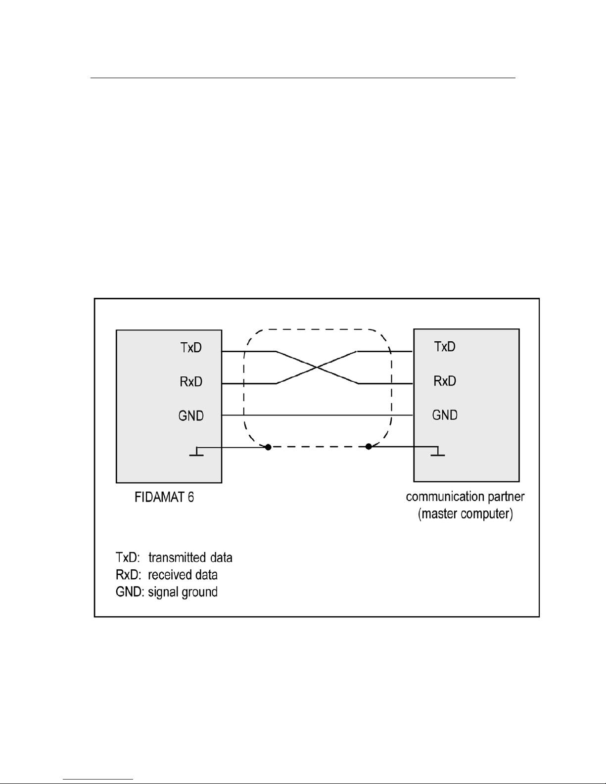
3.4.3.3 ELAN interface line
Specifications of the interface cable
Characteristic
impedance
100 to 300 Ω at a measuring frequency of
> 100 kHz
Cable
capacitance
Typically < 60 pF per meter
Core
cross-section
>0.22 mm
2
, corresponds to AWG 23
Cable type twisted pair, 1 x 2 conductors
Signal attenuation max. 9 dB over entire length of line section
Shielding Copper braiding, or braided shield and foil shield
Bus termination
resistors
Before bus termination resistors can be connected, in the first and last
connectors of a bus cable pin 3 has to be jumpered with pin 7, and pin 8
with pin 9 (see Fig. 3-4 "Pin assignments”).
Note
If the bus cable is longer than 500 m or there is a high level of
interference it is advisable to install a repeater. For further information see
function 73 in "ELAN configuration” on page 5-33 or in the description of
the ELAN interface.
Order number: C79000-B5200-C176 German
C79000-B5276-C176 English
Fig. 3-4: Pin assignments
Page 41

Installation instructions
FIDAMAT 6 gas analyzer
Operating manual – A5E00222135-01 3-11
3.5 Dimension drawings
Fig. 3-5: Dimension drawing of the FIDAMAT 6 (dimensions in mm)
Page 42

Installation instructions
FIDAMAT 6 gas analyzer
3-12 Operating manual –A5E00222135-01
Page 43

4. Start-up
4. Start-up
4.1. Safety instructions
4.2. Start-up preparations
4.3. Start-up and operation
4.3.1. Measuring ranges
4.3.2. Calibration
Page 44

Start-up
FIDAMAT 6 gas analyzer
4-2 Operating manual –A5E00222135-01
4.1 Safety instructions
Warning
It is essential that you observe the following information and instructions!
Explosion hazard!
Use of the FIDAMAT 6 gas analyzer for measuring operationally explosive
mixtures is not permitted. If the unit is to be used for measuring flammable
gases which in combination with air or oxygen could form an explosive
mixture, special explosion-protection measures will need to be taken.
Electrical safety
Certain parts of this device are carrying hazardous voltages. Before the
FIDAMAT 6 is switched on, the housing must be closed and grounded.
Failure to comply may result in death, physical injury or damage to
property. For this, please also note "
Electrical connection” on page 3-5.
Flushing the housing
In accordance with details in the technical data, there may be what is to
be regarded as a limited escape of flammable components from leaks in
the sample path. With the FIDAMAT 6 there is no need to flush the
housing provided it has been ensured that there is a natural exchange of
air from the environment. Your attention is particularly drawn to this in the
case where the analyzer is installed in a cabinet.
Warning
However, this does not apply to toxic or corrosive gases! When working
with corrosive or toxic gases the device must be flushed
Page 45

Start-up
FIDAMAT 6 gas analyzer
Operating manual – A5E00222135-01 4-3
4.2 Start-up preparations
Position of unit The FIDAMAT 6 may only be operated in a vertical position.
Gas conditioning Gas preparation takes place via a heated sample gas filter
(approx. 200°C) with a pore size of 3 µm and with a very limited capacity.
For this reason, samples with a high degree of contamination must be
prefiltered before entering the analyzer.
Check for leaks A leakage inspection should be conducted after any maintenance activity
affecting the flame ionization detector (FID) or the gas path. This is done
as follows:
FID
1. Connect
the sample gas outlet (exhaust gas) to a relative
pressure manometer
(0 - 1000 hPa, resolution 0.1 hPa)
2. Apply an overpressure of about 950 hPa at the sample entry and
close off.
3. Wait two minutes or so, until pressure equalization has occurred and
then make a note of the pressure.
4.
Wait another minute and then read off the pressure
The gas path is satisfactory as far as leaks are concerned when
the pressure drop within a minute does not exceed 10 + 2 hPa.
Note
The temperature of the gas path, including the FID, must remain constant
while this measurement is being taken.
Test conditions: The pressures given are relative pressures.
Test medium: Synthetic air (sample path must not become contaminated)
Test pressure: Operating pressure x 1.5 (operating pressure = 500 hPa)
Unit electrically switched off:
Test pressure [hPa]
Permissible pressure drop ∆ p [hPa]
Sample path
750 + 10 (750 + 10 hPa)
∆ p 10+2 (10 + 2 hPa)
Supply gas inlets
3,000 +100 (3,000 + 100 hPa)
∆ p 12+5 (12 + 5 hPa)
Page 46

Start-up
FIDAMAT 6 gas analyzer
4-4 Operating manual –A5E00222135-01
Pressure equalization times: time sequence of test
After application of test pressure, observe start and end of measurement for determination of ∆p.
Measurement starts x min after
application of test pressure
Measurement ends y min after
application of test pressure
Sample path
2 3
Supply gas inlets
1 2
Operation Before connecting up and switching on the unit, the operator must have
familiarized himself with how the unit is operated (see on page 5-2).
Interfaces
Before the unit is used, the interfaces must be correctly assigned and
parametrized (see "Connecting the signal lines” on page 3-6).
Noise damping The output signal fluctuations caused by noise in the measurement signal
can be reduced by means of function 50. Among other things, this
function allows you to parametrize a low-pas filter which can be assigned
a time constant of up to 300 s.
Temperature influence Make sure that the permissible ambient temperature of 5°C – 45°C is
observed during operation (see also "Technical data” on page 2-14).
Pressure influence If measurement is carried out externally, the unit will carry out an
automatic pressure correction. If there are pressure fluctuations within the
unit, pressure compensation will be carried out automatically.
Page 47

Start-up
FIDAMAT 6 gas analyzer
Operating manual – A5E00222135-01 4-5
4.3 Start-up and operation
Check Before switching the unit on, check to see that hydrogen, combustion air, zero
gas and test gas are connected and the required pressures are present.
Switching on
mains power Shortly after switch-on, the measured value display appears on the LCD
screen. Above this, on the top line, is the status display (Section 5.1).
Warming up
With the FIDAMAT 6 it is necessary to wait for about one hour for the
warming-up phase to finish. During this time, the oven heats up to 200°C
(accessible via function 2 "Diagnostics values”). In contrast, the
measuring cell and FID are warmed up with a delay whereby their
temperature derives from the setpoint temperature of the oven. Next, the
unit automatically checks in turn to see whether the corresponding
pressure of the sample and combustion air obtains and whether the
hydrogen supply is adequate. If this is the case, the flame is ignited
automatically. The flame burns when the flame temperature is 20°C
higher than the oven temperature.
Not until the unit has detected that the flame is burning will the pump be
switched on.
So as not to block the automatic heating-up procedure, the unit must be in
its measurement state. Here the current operational status can be read off
from the bottom line.
4.3.1 Measuring ranges
Measuring ranges and
measuring spans
The measuring spans desired (initial value of measuring range and final
value of measuring range) should be defined using function 41. Analog
current values 0/2/4 mA to 20 mA are assigned to the initial and final
values.
If the same values are assigned for a measuring range's initial and
starting values this measuring range will be deemed non-existent.
The smallest measuring span (MS) is to be assigned to measuring range
1, and so on. In general, the following arrangement will apply: MS1 < MS2
< MS3 < MS4
Setpoint value of zero point The setpoint value for the zero point is entered under function 22. It
applies to all measuring ranges.
Calibration of zero point Zero calibration is carried out with the aid of function 20. Here both the
setpoint value and the actual value are displayed.
Page 48

Start-up
FIDAMAT 6 gas analyzer
4-6 Operating manual –A5E00222135-01
Electronically suppressed
zero point If the measuring range initial value (ppm,% vol., etc.) is not at
concentration zero, we speak of measuring ranges with suppressed zero
point (for example, 200 - 300 ppm CO). Here 200 ppm is the initial value,
300 ppm the final value, and 100 ppm the measuring span.
Channels with electronic zero-point suppression are physically identical to
non-suppressed zero points. Where they differ is solely in the parametrization of the measuring ranges and of the setpoint value for the
suppressed zero point (200 ppm CO, for example).
The characteristic
curve
is stored from zero to the characteristic final value (as stated on
the nameplate). Units with non-suppressed zero points can be repara-
metrized subsequently to suppressed zero points by modifying this parameter (functions 22 and 41). It should however be noted that influences
such as noise, temperature and pressure errors are magnified by the
factor
F =
Final value of smallest measuring range
Final value of smallest measuring range – initial value
Here F should not exceed a value of 7. In general it is recommended to
increase the smallest measuring span by about 30%.
Span setpoint value The setpoint value for span should be checked under function 22.
The setpoint value displayed must be the same as the test gas value. If
this is not the case, the values must be made to coincide with the aid of
function 22.
With a total calibration, the leading measuring range should be selected.
The setpoint values must be as far away as possible from the zero point
(at least 60% of the corresponding full-scale value). The corresponding
test gases should be made available for the span calibration. The setpoint
value is input under function 22.
Changing measurement
ranges
For the largest measuring range (according to the nameplate) the
linearized curve is saved in the memory. If the largest measuring range is
changed (function 41) this final value must not be exceeded.
Dropping below the smallest measuring range (according to the
nameplate) is not permitted as in this case noise and the influence of
temperature on the measured value would increase relative to the
measuring range and reproducibility and drift behavior would deteriorate.
Page 49

Start-up
FIDAMAT 6 gas analyzer
Operating manual – A5E00222135-01 4-7
4.3.2 Calibration
Zero calibration Zero calibration is carried out with the aid of function 20. Here both the
setpoint value and the actual value are displayed.
Single and total
calibration Single calibration means that each measuring range is adjusted with its
own test gas. This is to be recommended when the changeover ratio of
the measuring spans exceeds 1:10.
With total calibration only the leading measuring range (function 22) is
adjusted; the other measuring ranges are "pulled in” via the changeover
ratio.
Total calibration can be activated or deactivated with the aid of function
23.
Next, select function 21 and carry out the calibration desired. In this
regard, note that this function cannot be selected unless AUTOCAL is
disabled.
Total calibration therefore means that all measuring ranges are adjusted.
With single calibration, the procedure described above has to be repeated
separately for each measuring range with the corresponding test gases.
(Under function 22 a test gas must be specified for each measuring
range!)
Calibration of zero point,
span Apply zero gas or test gas to the unit at 30 – 90 l/ h (0.5 – 1.5 l/ min).
Note here also the input pressures on page 2-14. Zero point calibration is
carried out with the aid of function 20, span calibration with function 21.
Examples of calibration
a) Detection of hydrocarbon in air
Measuring range: 0 - 20 ppm C
1
Test gas: 15 ppm methane in air
Zero gas: Synthetic air (free of hydrocarbons)
Procedure Function no. Input Comments
Selection of measuring
range initial and final
values
41 0 – 20 ppm
Inputting setpoint value
for zero points and span
22
Zero point: 0 ppm
Recommended:
15 ppm
Note input pressures
(see "Technical data” on page 2-14)
Calibration of zero point 20
Span calibration 21
Page 50

Start-up
FIDAMAT 6 gas analyzer
4-8 Operating manual –A5E00222135-01
b) Detection of hydrocarbon in air
Measuring range: 0 - 50 ppm C
3
Test gas: 90 ppm methane
Zero gas: Nitrogen (free of hydrocarbons)
Procedure
Function
no.
Input Comments
Selection of measuring range
initial and final values
41 0 – 50 ppm
Inputting setpoint value for zero
points and span
22
Zero point: 0 ppm C
3
Recom.: 30 ppm C3
90 ppm C
1
gives 30 ppm C3
Calibration of zero point 20
Span calibration 21
A detailed description of operator and input possibilities for the abovementioned functions may be found in Chapter 5 "Operation” starting on
page 5-1.
Page 51

5. Operation
5.1. General comments
5.2. Overview of operator functions
5.2.1. Diagnosis
5.2.2. Calibration
5.2.3. Measuring ranges
5.2.4. Parameters
5.2.5. Configuration
Page 52

Operation
FIDAMAT 6 gas analyzer
5-2 Operating manual –A5E00222135-01
5.1 General comments
Fig. 5-1: Display and control panel
Page 53

Operation
FIDAMAT 6 gas analyzer
Operating manual –A5E00222135-01 5-3
Switches / keys and their significance
Key Meaning
CLEAR Clears a numerical input which has been started
ENTER
Every numerical input (apart from fast selection of a function) must be confirmed with ENTER
ESC Goes back one step in the operator interface structure. Changes are accepted.
INFO Information about the current menu
MEAS
Return from any position in the operator interface structure in the display mode (if necessary,
the interrogation is done before accepting the entered data).
Pressing the MEAS key again will lock the analyzer
in other words, changing back again to operator mode is only possible after inputting the code.
Soft key
Variable significance; possibilities here include:
- Menu item selection in menu tree
- Selection function
Entering inputs The values shown in menus depicted in this section are for illustrative
purposes only.
• An active input field is shown with colons (for example: :10:) as
delimiters. Here the cursor appears as a flashing line beneath the number
to be input (for example: : 2
3.45 :).
•
• Pressing the ENTER key ends inputting and the value is saved. If
several input fields are present in a menu window, the cursor will
simultaneously be positioned over the next input field.
•
•
• Every value entered has to be confirmed with ENTER before leaving
the menu. This includes the last of multiple values in a menu.
•
• The CLEAR key clears a numerical input which has been started The
cursor then jumps back to the first position of the input field.
Graphic symbols
■ Switching function (ON state)
□ Switching function (OFF state; also status display on the status
line)
► Entry into a subsequent menu
● Initiation of a function (for example, Start calibration…)
Page 54

Operation
FIDAMAT 6 gas analyzer
5-4 Operating manual –A5E00222135-01
Fig. 5-2: Display and operator panel
Page 55

Operation
FIDAMAT 6 gas analyzer
Operating manual –A5E00222135-01 5-5
Attention
To prevent static charges the keyboard should only be used for
maintenance or operating purposes.
Operational sequence
Measured value display (measurement mode)
Entry into the main menu
The measurement component, furnished with a rightward pointing arrow
(►), appears on the right-hand side of the screen. A soft key is assigned
to this component. Pressing this soft key calls the main menu.
The main menu consists of the following sub-sections (sub-menus).
To their
right is shown the corresponding code level:
Diagnosis Not coded
Calibration Code level 1
Measuring ranges Code level 1
Parameters Code level 1
Configuration Code level 2
The code for level 1 is factory-set to "111” and that for level 2 is set to
"222.”
Entry into a
sub-menu
Once a sub-menu has been selected, you will be asked for the code for
the operator level (exception: the "Diagnosis” submenu is accessible
without restrictions).
Decoding level 2 also decodes level 1.
With decoding, signaling to the outside can take place via a relay contact
provided a corresponding relay has been configured via function 71 with
CTRL. The warming-up and calibration phases of the unit are also
signaled via this relay contact.
With decoding the measured value memory is also activated, provided it
was set under function 77. The coding of the unit is to be seen on the
display (Fig.:
Measured value display) as the symbol ■ CODE,
decoding with
□ CODE.
Page 56

Operation
FIDAMAT 6 gas analyzer
5-6 Operating manual –A5E00222135-01
Return to
measuring mode
From any location in the menu structure, pressing the MEAS key will take
you back immediately to measuring mode. Any input you may have
started will be aborted.
Before the jump, the question shown on the left will appear.
Pressing the YES or NO soft keys takes you back to measuring mode.
YES causes the changes to be saved in the main memory of the
parameter memory, NO discards them.
Pressing the ESC key takes you back to the last function screen.
Changes are accepted without checking with you first.
Coding the unit
Following a return via ESC or MEAS to measuring mode, the unit can
be coded again by pressing MEAS again
(■ code) and thus returned to measuring mode. All states brought into
existence with decoding are thereby cancelled.
Quick selection of
functions In the case of frequent operator activity a "power user” feature has been
implemented to allow the user to go directly to the desired function screen
from the "Measured value display” screen. This allows direct access to the
desired settings by inputting functions. This simply bypasses menu levels.
However these functions can only be launched from measuring mode and
include the following operator steps:
• In measuring mode ("Measured value display” screen), input
the number of the desired function using the number key.
• Press the soft key with the ► arrow.
• If the desired function is protected by a code, you will be
asked to input the code (see "Entry into the main menu”).
Page 57

Operation
FIDAMAT 6 gas analyzer
Operating manual –A5E00222135-01 5-7
5.2 Status diagram
Fig. 5-3: Status diagram
Page 58

Operation
FIDAMAT 6 gas analyzer
5-8 Operating manual –A5E00222135-01
Change of state following error/maintenance request
Fault / maintenance request State before State after
S1: Parameter storage - - S2: Pump does not start warm-up / stand by stand-by
S3: Flame does not ignite warm-up pause
S4: External fault - - S5: Oven temperature warm-up / stand-by / measure / pause pause without heating
S7: Flame temperature warm-up / stand-by / measure / pause pause
S8: Combustion air/gas pressure warm-up / stand-by / measure / pause pause
S9: Heating switched off warm-up pause without heating
S10: 24h RAM/flash check - - S12: Mains power supply warm-up / stand-by / measure / pause pause
S13: Hardware / mains frequency warm-up / stand-by / measure / pause pause
S14: Measured value > full-scale value - - S15: Calibration cancelled - - -
W1: Calibration tolerance exceeded - - W4: Set clock - - W5: Combustion air/gas pressure stand-by / measure warm-up
W6: Temp. sensor LCD display - - W7: Electronics / analyzer temperature - - W8: Flame out Stand-by / measure warm-up
W9: External maintenance request - - W10: Autocal check deviation - - -
Page 59

Operation
FIDAMAT 6 gas analyzer
Operating manual –A5E00222135-01 5-9
5.3 Overview of operator functions
The unit functions are shown below in an overview. This listing corresponds to version 4 of the software.
Subsection of main menu
Function
no.
Name of function
5.2.1. Diagnosis
1
2
3
4
Factory data
Diagnostic values
Logbook
Display measuring ranges
5.2.2. Calibration (Code 1)
20
21
22
23
24
Calibration of zero point
Span calibration
Setpoint values of zero / span
Calibration settings (single and total calibration)
AUTOCAL / check (only with option card)
5.2.3 Measuring ranges
5.2.3 (Code 1)
40
41
Select measuring ranges
Define measuring ranges
5.2.4. Parameters (Code 1)
50
51
52
53
54
55
56
57
58
59
60
61
Electrical time constants
Limits
In and out functions
Status messages
Graphic representation of measured values
Measured-value display
LCD contrast
Ignite flame
Date and time
Measurement point changeover
Logbook setting
Switch internal valves
5.2.5 Configuration (Code 2)
70
71
72
73
74
75
76
77
78
79
80
81
83
85
86
87
88
90
91
92
93
99
Analog output
Relay assignments
Binary inputs
ELAN configuration
Reset
Save or load data
Suppression of brief fault signals
Analog output memory
Calibration tolerances
Change codes
Unit test
Language selection
Accompanying gas correction
Switch valves
Linear temperature compensation
Fault on/off
AK (only with optional board)
PROFIBUS configuration (only with optional board)
Start-up state
Pressure values
Units
Factory settings
Table 5-1: Overview of operator functions
Page 60

Operation
FIDAMAT 6 gas analyzer
5-10 Operating manual –A5E00222135-01
5.3.1 Diagnosis
When the diagnostic functions are selected in the main menu by pressing
the first soft key ("Diagnosis”) the adjacemt display appears.
Access to diagnostic functions is not restricted. For this reason you will
not be asked for the code.
Every unit provides the following diagnostic functions:
1 Factory data When this function is selected, important manufacturer's data for the unit
are displayed:
Motherboard:
• Firmware no.:
Order number of the software held in the EPROM for the
motherboard
• Order no.:
Information about ordering data for the unit
• Serial no.:
Information about date of manufacture and unit serial number
• Article status:
Information about hardware configuration of the unit
• Software status and date
Information about the unit's functional scope at the motherboard
2 Diagnostic values The most important diagnostic values are listed under function 2. They
may allow conclusions to be drawn for evaluating setting activities or
errors.
3 Logbook In the logbook will be found a list of all errors which resulted in a
maintenance request (W) or a fault message (S). (see also on page 6-5
"List of maintenance requests”)
Limit alarm (LIM) and function check (CTRL) are also recorded.
These, however, do not trigger a maintenance request or fault message.
The logbook contains a maximum of eight pages, each of which can hold
four messages. It works on the principle of the cyclic buffer – in other
words, when all eight pages (all 32 slots) are occupied, the oldest
message will be overwritten.
Logbook entries can be deleted or locked (function 60) and even switched
off individually (function 87).
Note
If an error occurs and its error message has been switched off with
function 87, there will be no reaction at an interface which may have been
configured. This applies to the ELAN interface and also to the analog
output and relay output.
Page 61

Operation
FIDAMAT 6 gas analyzer
Operating manual –A5E00222135-01 5-11
In the case of maintenance, function 110 Diagnostic service should also
be taken into consideration. This menu is however only accessible to
maintenance personnel.
4 Display measurement
ranges
The measuring ranges defined under function 41 are listed under
function 4. However, they cannot be modified in this menu.
5.3.2 Calibration
If at all possible, calibration should be carried out using test gases which
very closely resemble the sample both in composition and concentration.
If the measuring task is to measure hydrocarbons in nitrogen, a hydrocarbons in nitrogen test gas should also be used. If, for example, propane
in synthetic air were to be used here, the measurement result would be
falsified by the response factor of the methane compared with the
propane and by the oxygen error.
The FIDAMAT 6 provides both manual and automatic calibration
(AUTOCAL: function 24). The latter is only possible with the aid of an
optional board which in addition contains eight binary inputs and eight
relay outputs.
Setpoint values for zero-point and span calibration must be set under
function 22.
20 Zero-point calibration
Calibration of the zero point is carried out for all measuring ranges
simultaneously even if the span of the measuring ranges is being adjusted
individually.
The calibration procedure should not therefore be initiated until the
measured value (actual value) has stabilized following addition of the zero
gas.
If the measured value fails to settle, the time constant (function 50) should
be increased before carrying out calibration.
Page 62

Operation
FIDAMAT 6 gas analyzer
5-12 Operating manual –A5E00222135-01
21 Span calibration of
Single calibration:
The display shows as many measuring ranges as was previously defined
via function 41. The adjacemt display therefore represents an example of
single calibration of four measuring ranges.
If measuring range 3, for example, is to be adjusted, the corresponding
softkey should be pressed.
The setpoint value and the current (ACTUAL) value for measuring range 3
appear on the screen.
Once the actual value has stabilized, the calibration procedure can be
started by pressing the fourth soft key. The actual value is now brought
into agreement with the setpoint value.
In the case of an inadvertently incorrect calibration (after using the wrong
calibration gas, for example), pressing the "ABORT" soft key will reload
the original calibration.
Total calibration:
Total calibration means that all measuring ranges are adjusted
simultaneously. The "leading” measuring range is defined under function
22 (see also menu 23 "General and single calibration”). It makes sense to
select the largest measuring range as the leading range.
The setpoint value and the current value for the "leading” measuring
range appear on the screen.
Once the actual value has stabilized, the calibration procedure can be
started by pressing the fourth soft key. The actual value is now brought
into agreement with the setpoint value.
In the case of an inadvertently incorrect calibration (after using the wrong
calibration gas, for example), pressing the "ABORT" soft key will reload
the original actual value.
22 Setting setpoint values
The adjacent example to the left shows setpoint value input in the case of
total calibration. The fourth measuring range has been chosen as the
leading measuring range.
In the case of single calibration, it is not possible to specify the leading
measuring range.
Page 63

Operation
FIDAMAT 6 gas analyzer
Operating manual –A5E00222135-01 5-13
23 Total and
single calibration:
This function is used for selecting general or single calibration of the
measuring ranges.
With total calibration a "leading measuring range” is adjusted and all of
the other measuring ranges are "pulled in” via the changeover ratio.
If this function is not activated (see illustration), each measuring range will
be adjusted individually.
24 AUTOCAL
Automatic calibration (AUTOCAL) cannot be carried out unless the unit
has an additional electronic module (optional board).
If it does not and an AUTOCAL parameter is selected, the corresponding
message will be shown on the display.
AUTOCAL / check
operating mode
This subfunction allows you to parameterize various AUTOCAL operating
modes.
AUTOCAL / Check on / off
When the "AUTOCAL off” state is active (shown as
□) it will not be
possible to operate the "AUTOCAL Start by cycle” (parameter) or
"AUTOCAL Start by binary input” switches.
Even "AUTOCAL run once”
is switched off. The cycle time continues to run. Nevertheless no
automatic calibration is initiated.
AUTOCAL / check Start by cycle
AUTOCAL can be activated to use a regularly repeating cycle provided
the "Time between two AUTOCALs” has been set.
"AUTOCAL – check” is used for checking the calibrations. As with
"AUTOCAL”, the sequence parameterized in the "AUTOCAL sequence”
menu is carried out. In contrast to "AUTOCAL” no new calibrations are
however performed, but deviations from selectable calibration tolerances
are checked.
Page 64

Operation
FIDAMAT 6 gas analyzer
5-14 Operating manual –A5E00222135-01
AUTOCAL / check Start by binary input
AUTOCAL can be activated via a binary input provided one has been
configured with the aid of function 72.
AUTOCAL run once
In the "AUTOCAL on” state, an AUTOCAL sequence can be started at
any time by means of the "AUTOCAL run once” soft key – provided the
unit is in the measuring state. A run initiated in this way does not have any
influence on the time cycle of an AUTOCAL run – in other words, the
cycle time continues to run independently of this.
After AUTOCAL initiation, this item disappears until the process has
completed.
AUTOCAL abort
An automatic calibration run which is in progress can be stopped at any
time by means of the "AUTOCAL abort” soft key. This results in all
calibration data so far obtained being discarded and the calibration data
valid before AUTOCAL started (zero point and span) being used as
previously.
Aborting in this way has no effect on the time cycle. All valid calibration
events are retained.
AUTOCAL sequence
This subfunction allows you to group several calibration phases into one
AUTOCAL sequence.
The sequence used for automatic calibration can be defined as you see
fit. It is possible to put together a sequence consisting of as many as
twelve different phases.
In addition to inputting a zero gas and up to four test gases for each
component, you can also program in flushing with sample gas, and a
sample gas intermediate operation period as well as a signaling contact.
This signaling contact will be available provided it has already been
assigned to a relay output by function 71.
Sample gas intermediate
operation A sample gas intermediate operation period may become necessary
if the system is only permitted to leave measurement mode for a very
specific time. If the necessary flushing times then add up to a period
greater than the permitted outage time, there must be a return to
measurement mode between the individual calibration runs.
Signaling contact The signaling contact can, for example, be used for starting an
automatic calibration run in a second unit or for signaling the start or
end of an AUTOCAL run.
Relay outputs If relay outputs have been defined for sample, zero gas, test gases
and / or measurement or calibration (function 71), the corresponding
external solenoid valves will be operated via these outputs. The same
applies to the "AUTOCAL" signaling contact as well – this is closed for
about one second when the command is being executed.
Page 65

Operation
FIDAMAT 6 gas analyzer
Operating manual –A5E00222135-01 5-15
Example:
The following sequence is to be programmed:
1. Zero gas calibration, with zero gas flushing after 15 minutes
2. Calibration with test gas 1, with flushing with test gas after
10 minutes
3. Flushing with sample: 8 minutes
4. Sample gas intermediate operation: 30 minutes
5. Calibration with test gas 2, with flushing after 8 minutes
6. Calibration with test gas 3, with flushing after 8 minutes
7. Calibration with test gas 4, with flushing after 10 minutes
8. Flushing with sample: 8 minutes
9. Momentary signaling contact so as to be able to start
"AUTOCAL" in another unit or channel.
Note
The FIDAMAT 6 only has one connection for test gas. Additional test
gases will need to be connected up externally and switched using
external valves.
The AUTOCAL sequence specified is shown in the screen to the left.
List for the AUTOCAL sequence:
Step Component
Zero gas 1 Component 1
Zero gas 2 – " –
Test gas 1 – " –
Test gas 2 – " –
Test gas 3
– " –
Test gas 4 – " –
Flush sample
Sample intermediate
operation
Signaling contact
Zero gas 1b Component 2
Test gas 1b – " –
Test gas 2b – " –
Test gas 3b – " –
Test gas 4b – " –
Page 66

Operation
FIDAMAT 6 gas analyzer
5-16 Operating manual –A5E00222135-01
Note
Zero gas 2 is not used with the FIDAMAT 6!
AUTOCAL / check Cycle parameters
With this subfunction various time constants for activating a cyclically
repeating AUTOCAL run can be parameterized.
• Time between two AUTOCAL cycles.
Any setting between 0 and 1 (hour) will be accepted by the unit. Here
a "0” does not correspond to any AUTOCAL cycle.
• Time until the first AUTOCAL run (from time when setting made).
If a "0” is input here and AUTOCAL is switched on (see "AUTOCAL
on / off”) the analyzer will start the AUTOCAL sequence immediately.
If AUTOCAL is switched off, the unit will not start an AUTOCAL
sequence unless AUTOCAL is switched on within a minute of the "0”
being input. If this does not occur, from time the "0” is input the entire
time between two AUTOCAL cycles will be cancelled.
This internal clock will therefore run even when AUTOCAL is
switched off! It starts the first time the unit is switched on, and needs
to be reset to the current time via function 58.
• Number of cycles before test-gas calibration is performed.
With every AUTOCAL run the zero point is calibrated. If, in order to save
on test gas, the span is not to be adjusted as well every time the zero
point is calibrated, a value greater than 1 must be entered in the line
"Perform test gas calibration every : : cycle.”
Note
As long as AUTOCAL is activated (AUTOCAL
■), access to functions
20 and 21 will also be blocked.
Should you still attempt to access the
functions, a corresponding message will appear in the display.
Page 67

Operation
FIDAMAT 6 gas analyzer
Operating manual –A5E00222135-01 5-17
Sequence of AUTOCAL check
1. Input the desired calibration tolerances in the "AUTOCAL check”
menu. If necessary, select the relay output and binary input for
"AUTOCAL check”.
2. Start the "AUTOCAL check” by the key in the "AUTOCAL check”
menu or via binary input.
3. The unit now performs a run as parameterized in the "AUTOCAL
sequence”.
4. Should an calibration limit be crossed, maintenance request W10
will be issued and also, if parametried, the relay "Acal Chk Dif.”
set.
5. Following a fault-free AUTOCAL run they will both be reset.
W10 will be retained in the logbook.
5.3.3 Measuring ranges
When the measuring range functions are selected in the main menu by
pressing the third soft key ("Measuring ranges”) the adjacemt display
appears.
40 Select measuring ranges
It is possible to select a fixed measuring range or to switch over to
automatic measuring range changeover. All possible selections are
subject to mutual interlocking.
Automatic measuring range changeover is possible under the following
conditions:
• At least two measuring ranges must be available. A measuring
range is deemed present when:
• measuring range initial value ≠ full-scale value
• The measuring spans must be made larger
• The measuring range must adjoin each other or overlap
This yields the following permitted measuring range arrangements which
are shown in the following diagrams:
Page 68

Operation
FIDAMAT 6 gas analyzer
5-18 Operating manual –A5E00222135-01
Only two measuring range types are distinguished:
type A: The full-scale value must be less than the full-scale value which follows it. This
means that the upper measuring range limit is higher with each successive
measuring range.
smr : start of measuring range
emr: end of measuring range
LP: lower changeover point: select
smaller measuring range
UP: upper changeover point: select
larger measuring range
The following applies to measuring range changeover:
Page 69

Operation
FIDAMAT 6 gas analyzer
Operating manual –A5E00222135-01 5-19
If the upper changeover point (OU) is crossed, the next largest available
measuring range will be selected. If the lower changeover point (UU) goes below
that of the next smallest available measuring range, this will be selected. The UU
is located at 80% (HystA) of the measuring range. The OU is located at 90%
(HystE) of the measuring range.
type B: The full-scale value must be greater than or equal to the full-scale value
which follows it. Since the measuring spans must at the same time become
larger, the measuring range initial values of the following measuring ranges
must always be smaller.
smr : start of measuring range
emr: end of measuring range
LP: lower changeover point: select
smaller measuring range
UP: upper changeover point: select
larger measuring range
The following applies to measuring range changeover:
If the upper changeover point (OU) is crossed downwardly, the next largest available measuring range will
be selected. If the lower changeover point (UU) of the next smallest available measuring range is exceeded,
this will be selected.
The UU is located at 10% (100% - HystE) of the measuring range.
The OU is located at the start of the measuring range (mba).
41 Define measuring ranges
A maximum of four measuring ranges can be defined whose initial values
are assigned to the lower value (0/ 2/ 4 mA) and whose final values are
assigned to the upper value (20 mA) of the analog output.
If the message "Measuring ranges implausible” appears, this means that
automatic measuring range changeover is not possible.
If the initial or final value is 0, the measuring range will be switched off.
Page 70

Operation
FIDAMAT 6 gas analyzer
5-20 Operating manual –A5E00222135-01
5.3.4 Parameters
Following selection of parameter functions in the main menu by pressing
the fourth soft key ("Parameters”) the adjacemt display appears, showing
parameter functions 50 to 53. If you press the fifth soft key ("…more”), this
will display parameter items 54 to 61 instead.
50 Electrical time constants With the aid of this function various time constants which reduce noise
can be set. The reduction feature corresponds more or less to a low-pass
filter with the corresponding time constant. The display delay is shown in
90% time.
The time constant ti is effective within an action interval which is to be
parameterized and which is defined as a percentage of the smallest
measuring span. On the one hand it damps minor changes in measured
value (noise, for example) but has no effect immediately the measured
value exceeds the action interval. In this case the measured value is
damped by the external time constant ta.
Values up to 100% can be parameterized for the action interval and
values up to 300 s for the time constants ti and ta. A low display delay
(90% time) can still be achieved by a skilful combination of these three
parameters despite a high level of noise suppression.
The effect of the damping parameters set can be observed on the bottom
line where the measured value is shown "live.”
51 Limits For each measurement component the unit can monitor up to four limits
which can be assigned to the measuring range as desired.
Any relay can be assigned to each limit (see function 71).
Only positive limit values up to 100% can be parameterized.
Furthermore, you can specify whether a limit alarm should be activated
when the limit value entered is exceeded or fallen below.
The limit value is assigned to the measuring range by repeatedly pressing
the third soft key. Here pointers travel above the boxed measuring range
identification numbers and indicate the measuring ranges where limit
monitoring is to be activate (in the example to the left this is measuring
range 3).
Page 71

Operation
FIDAMAT 6 gas analyzer
Operating manual –A5E00222135-01 5-21
Limit monitoring can be switched off individually for any limit value (see
also function 52).
Tripping of a limit relay is recorded in the logbook (function 3). As soon as
the cause of this disappears, the limit relay will reset automatically.
If you press the fifth soft key ("…more”), the program will jump to the next
limit screen.
52 On / off functions
Unit-specific on / off functions can only be accessed via the first
component.
This menu allows you to switch off in a simple manner the functions which
are listed in the adjacemt display.
This simplified operator action means that the longer routes through the
various menu levels are not needed for these functions. However, for the
sake of clarity, the function numbers are still quoted.
Activated functions are indicated by ■, inactivated by □. If you press
the fifth soft key ("more”), the program will jump to the next screen.
Page 72

Operation
FIDAMAT 6 gas analyzer
5-22 Operating manual –A5E00222135-01
The following functions are switched on or off with the aid of function 52:
Key F. no. Comments
Total calibration 23
Autoranging 40
Limit monitoring 1 51
Limit monitoring 2 51
Limit monitoring 3 51
Limit monitoring 4 51
Suppress negative measured values for display 55
Block logbook 60
Suppress negative measured values 70
Fault / Maint. Req. / CTRL / NAMUR 72
Analog output memory 77
Signal tolerance exceeded 78
Temperature re-compensation of zero point 86
Temperature re-compensation of span 86
Temperature compensation 102 Accessible for maintenance only
Pressure compensation 104 Accessible for maintenance only
TC precompensation 111 Accessible for maintenance only
Linearization 113 Accessible for maintenance only
Table: 5-2: These functions can be selected via function 52
In addition to the functions listed in Table 5-2, additional maintenance
functions can be accessed with the aid of function 52. These are reserved
for the use of maintenance personnel only and are hidden until the
maintenance code (code level 3) is input.
53 Status messages
With the aid of this function a maximum of three different states can be
shown in the measured values display.
Functional check shows the current state of the unit (for example,
warming-up phase, calibration, and so on) or which actions the operator
should carry out (for example, decoding the unit). After quitting a menu,
press the MEAS key twice. If you do not do so, the analog output will
remain with the fault current.
Note
If functional check is active, this could result in falsification of the
measured value. Since the functional check is no longer displayed, the
measured value will have to be checked.
Page 73

Operation
FIDAMAT 6 gas analyzer
Operating manual –A5E00222135-01 5-23
Status Displayed on screen depending on functions 52 and 53
Ft. 53 □
Ft. 52 □
Ft. 53 ■
Ft. 52 ■
Ft. 53 ■
Calibration: CAL
None CAL
□ CAL
■ CAL Calibration in progress (also in
AUTOCAL)
Measured-value memory: STO
None STO
□ STO
■ STO Analog output connected to memory
(see function 77 on page
5-36)
Limit: LIM
None LIM
□ LIM
■ LIM Limit exceeded or fallen below (see
function 51 on page
5-20)
Automatic measuring range
changeover: AR
None AR
□ AR
■ AR Measuring range changeover (active
possible) (see function 40 on page
5-17)
Functional check: CTRL
None CTRL
□ CTRL
■ CTRL Unit is not in measurement mode /
warming
-up phase /
Calibration in progress
Table 5-3: Status message The status type "Code” always appears on the status line. Should a
fault occur during operation, the message "Maintenance request”,
"Fault” and "Measurement protection” will appear on the status line,
depending on the weighting given to the fault. This message is
displayed in alternation with the status messages.
In addition, with communication via the ELAN interface – also alternating
– the message "Remote” will appear, together with the unit state.
54 Graphic
measured value representation
This function allows you to track on screen the measured value time
curves for the last 10 minutes or 24 hours.
Following selection of a time axis (time period) the measured value is
plotted against the time axis. The very latest measured value is located at
the extreme left of the time axis at t = 0.
Page 74

Operation
FIDAMAT 6 gas analyzer
5-24 Operating manual –A5E00222135-01
Under "Parameters” a specific measuring range can be assigned to the
measured value axis. In addition there is also the possibility of an
"optimum measured value display.” This means that when this parameter
is activated the program automatically carries out rescaling of the
measured value axis. Here the scale is adjusted to suit the measured
value scatter.
55 Measured-value display
This function allows you to suppress output of negative measured values.
It is also possible to specify the total number of positions and the number
of positions after the decimal point.
It should be noted that no more than five positions can be displayed (the
decimal point counts as one position).
56 LCD contrast
With this function you can adjust the contrast of the display to a brighter or
darker setting.
If the contrast is set wrong, by pressing the third soft key ("Default
setting”) you can restore the contrast set in the factory.
It is also possible to carry out an LCD test by pressing the fourth soft key
("test”). A succession of test images is displayed.
If the LCD was grossly incorrect and the unit is in measured value display,
if you press the key sequence
ENTER, you can restore the default setting.
8 8 8 8
Page 75

Operation
FIDAMAT 6 gas analyzer
Operating manual –A5E00222135-01 5-25
57 Ignite flame
To get the FID running the hydrogen flame must be ignited.
This is done via function 57.
Ignition is activated or deactivated by pressing the second hot key.
In addition, the temperature of the flame and of the sample stream are
shown on the display.
When the flame is burning, "Flame burning” appears on the display. If the
flame goes out, this message disappears.
58 Date and time
With this function you can set the time and date precisely.
When the function is called, the presets shown in the screen shot on the
left appear in the display.
The cursor will already be standing on the first position of the date display
which can be changed in the order day, month, year. The same procedure
applies to the time (hours, minutes).
The unit has a system clock which is not protected against power failure
(not a real-time clock).
Attention
When switched off, the clock remains at a standstill and is not updated.
The main importance of the settings is for trouble-shooting. With the aid of
the time and date it is easier to classify faults which have occurred and
which are always recorded in the logbook (function 60).
By pressing the third soft key ("Set clock”) the data which have been set
are taken over for use. They will then appear at the bottom edge of the
screen.
Page 76

Operation
FIDAMAT 6 gas analyzer
5-26 Operating manual –A5E00222135-01
59 Measurement point changeover
This function allows you to assign a maximum of six measurement points
and to cycle through them automatically.
What this requires is that the measurement point relays have already
been parameterized via function 71 ("Relay assignment”) and these will
then control the corresponding solenoid valves.
A time duration is also assigned to each measurement point relay and is
to be input into the corresponding editing field. For this, values between 0
and 60 (minutes) are possible.
If you press the fifth soft key you can switch measurement point
changeover on and off.
It is also possible to assign a signal relay to each measurement point
relay. This will make possible a measurement point identification which is
separate from the measurement point relay. These signal relays will also
need to be configured via function 71.
60 Logbook settings
With the aid of this function, logbook entries can be deleted or locked (see
also function 3).
The logbook entries can also be deleted by the key
sequence ENTER.
This is, however, only possible in the measured value display.
5 5 55
This cannot be used for suppressing status messages such as
maintenance requests or fault messages which will still be displayed even
if the logbook is locked.
61 Internal valves
With the aid of this function, the internal valves can be operated to control
the gases.
Pressing the corresponding soft key activates or de-
activates □ the valves.
The internal valves open or close the hydrogen, combustion air, zero gas
and test gas streams.
Page 77

Operation
FIDAMAT 6 gas analyzer
Operating manual –A5E00222135-01 5-27
5.3.5 Configuration
All of the following functions in this block are only accessible via the level
2 code.
Entry menu
When the configuration functions have been selected in the main menu,
pressing the fifth soft key ("…more”) takes you to more configuration
functions.
70 Analog output
With the aid of this function you can determine the lower value of the
measuring range 0 - 20 mA/ 2 - 20 mA/ 4 - 20 mA/ NAMUR = 4 - 20 mA
with limit at 3.8 mA. See also the table below.
The desired value is selected by pressing the soft key assigned to it and
simultaneously the two other values are reset.
In addition, the analog output can be negated; for example, 0 … 100 ppm
THC ≡ 0 ... 20 mA or 0 ... 100 ppm THC ≡ 20 ... 0 mA.
Note
The second analog output is not used.
Negative measured values: Should negative measured values prove to be
unsuitable for further processing, by activating this function you can limit
the negative measured values at the analog output to 0 (or 2/ 4/ 3.8
(NAMUR)) mA. The display continues to show the correct measured
value.
Measured-value limitation during
normal operation
Measured-value limitation during
fault / CTRL
Defined analog
output / mA
Initial value [mA] Final value [mA] Initial value [mA] Final value [mA]
0 - 20 -1 21 0 21
2 - 20 1 21 2 21
4 - 20 2 21 4 21
4 -20 (NAMUR) 3.8 20.5 3 21.5
Table 5-4: Measuring ranges
Note
A defective electronics module may cause the analog output to remain
fixed at approx. -1 mA or approx. +24 mA.
Page 78

Operation
FIDAMAT 6 gas analyzer
5-28 Operating manual –A5E00222135-01
71 Relay assignment
In the basic unit, six programmable relays are available. Their reversible
output contacts (max. 24 V / 1 A) can be used for signaling, controlling
valves, and so on.
Should these six relays be insufficient it is possible to obtain a further
eight relays by installing an additional electronics module (option).
One of the functions listed in Table 5.4 can be assigned to each relay but
each function may only be assigned once. What this means is that a fault
signal, for example, cannot be sent to two relays.
Pin assignments for the individual relays in the non-energized state can
be seen in the assignments diagram "Electrical connections” on page 3-5.
The unit is shipped with the relays preset.
Up to four inputs can be configured in a menu screen. Switching to further
menu screens – and thus to more binary inputs – is always done by
pressing the fifth soft key ("…more”).
Page 79

Operation
FIDAMAT 6 gas analyzer
Operating manual –A5E00222135-01 5-29
Function
Relay is passive
when
Relay is carrying a
current
Comment
Unassigned
Relay is permanently passive
(at zero current)
Fault Fault
Maintenance request
Maintenance
request
Also appears on the display
(measuring mode)
(see Section 6.5)
Calibration Calibration in progress For identification
Measuring range
1 (...4)
Measuring range
1 (...4) on
Measuring range detection
Limit 1 (...4)
Limit 1 (...4) has
responded
Limit signaling
Functional check
(CTRL)
Functional check
on
Decoding, warming-up
phase, AUTOCAL in
progress
Calibration in progress
Signaling when:
• Unit is decoded
• Warming-up phase (max. 2 h)
• Calibration in progress
(AUTOCAL)
Sample Supply of sample
Zero gas 1 Supply of zero gas
Test gas 1 (…4) Supply of test gas
Control of the valves
Measurement point
1 (...6)
Measurement point 1 (…6)
selected
For gas extraction via solenoid
valves at different measurement
points
Signal – measurement
point 1 (...6)
Measurement point 1 (…6)
selected
For measurement-point
identification (runs in parallel with
measurement point)
Signaling contact
During signaling the relay
briefly carries a current
For example, with AUTOCAL:
control of a second unit
Heating – gas path
Heating ready for
operation
For identification
AUTOCAL / check
AUTOCAL difference too
great (function 24)
Hydrogen Hydrogen valve is open Control of the valves
Combustion air
Combustion air valve is
open
Control of the valves
Table 5-5: Relay assignments
Page 80

Operation
FIDAMAT 6 gas analyzer
5-30 Operating manual –A5E00222135-01
72 Binary inputs
In the basic version of the unit, six floating binary inputs are available
['0' = 0 V (0...4.5 V); '1' = 24 V (13 ... 33 V)] which can be configured as
required. Should these six inputs be insufficient, you will need to install an
additional electronics module with a further eight binary inputs (optional).
This is where the manner of functioning of the binary inputs is defined.
With the operating mode NAMUR (■) the binary inputs behave as
shown in Table 5.6 by 'N'.
If operating mode NAMUR is not activated (□), the binary inputs will
behave compatibly with the software edition states of the older version
V4.3.0 (marked with 'X' in Table 5.6).
One of the control functions listed below can be assigned to each input as
required but each function may only be assigned once.
Pin assignments for the individual inputs can be seen in the assignments
diagram 'Electrical connections' on page 3-6.
The unit is shipped with none of the binary inputs preset. Up to four inputs
can be configured in a menu screen. Switching to further menu screens –
and thus to more binary inputs – is always done by pressing the fifth soft
key ("…more”).
Attention
It is essential that any changes made to the configuration of the binary
inputs are saved to the user data memory by means of function 75.
Failure to do so runs the risk of an earlier (and unwanted) configuration
being accessed when 'Load user data' (function 75) is executed.
Page 81

Operation
FIDAMAT 6 gas analyzer
Operating manual –A5E00222135-01 5-31
Driving functions / NAMUR
Function Driving voltage required Comment / effects
0 V 24 V 24 V (min.1 s)
Unassigned No effect when addressed
External fault 1, 2, ..., 7 N X
External maintenance request
1, 2, ..., 7
N X
e.g.: Signaling by a gas preparation
unit: condensate overflow,
gas cooler defective or similar
Deletion of logbook entries N, X
Manual deletion of logbook entries is
possible. But if the cause of a fault or a
maintenance request has not yet been
corrected the corresponding message will
reappear in the logbook.
Functional check (CTRL) 1 … 4 N X
Relays under function 71 must be
configured for a functional check if, for
example, the function is to be checked in
the case of a second unit.
AUTOCAL N, X
AUTOCAL must be parameterized (function
24)
Measuring range 1 (... 4) N, X
For remote measuring range changeover,
autoranging (function 52) must be
deactivated.
Zero gas N, X
Relay must be configured for zero gas and
the corresponding valves connected.
See also example 1, below
Test gas N, X
Relay must be configured for sample and
the corresponding valves connected.
See also example 1, below
Sample N, X
Relay must be configured for sample and
the corresponding valves connected.
Before the sample gas valve is opened, the
other valves must have been connected.
The unit then switches to measurement
mode and all other processes which had
previously been activated (such as
calibration) are aborted.
Zero-point calibration
Span calibration
N, X
Start calibration
See also example 1, below
Autorange N, X Automatic measuring range changeover
AUTOCAL / check N, X Start AUTOCAL check (function 24)
Measurement protection N, X
A "Measurement protection” binary input
can be defined which has the following
effect:
if the unit is in the "Measurement'” state (no
functional check), it will remain in this state;
in other words:
- the unit can no longer be decoded
- the unit can no longer be set to "Remote”
- The message "Measurement protection
switched on” appears on the status line
of the measurement screen.
Table 5-6: Driving functions
The meaning of "N" and "X" in the "Driving voltage” columns is explained
in function 72 "Binary inputs.”
Page 82

Operation
FIDAMAT 6 gas analyzer
5-32 Operating manual –A5E00222135-01
Example 1:
The following procedure allows you to adjust the measuring range via the
binary inputs.
1. Zero gas:
The "Zero gas'” relay is opened and thus switches into calibration
mode.
2.
Test gas:
Relay 1, 2, 3 or 4 of the test gas is opened. Distinguishing which
relay is concerned will be made clear by the following differentiation:
•
With total calibration ON:
The relay corresponds to the measuring range number which has
already been selected under function 22 (on page 5-12).
•
With total calibration OFF:
The relay corresponds to the measuring range number of the
measuring range currently selected.
3.
Zero-point calibration is carried out.
This will not take place until the previous steps have been carried out
and the setting "Common zero-point calibration ON” has been
enabled. This means that it is necessary for the unit to be in
calibration mode.
4.
Span calibration is carried out.
Here too it should be noted that the unit must be in measurement
mode for the calibration actually to be carried out. The measuring
range currently selected is adjusted.
The following diagrams should make the procedure clear:
Fig. 5-3: Range calibration (zero gas)
Page 83

Operation
FIDAMAT 6 gas analyzer
Operating manual –A5E00222135-01 5-33
Fig. 5-4: Range calibration (calibration gas)
Note
In this regard you should also note the explanatory material under
function 40 "Selecting measuring ranges” on page 5-17.
73 ELAN configuration
With the aid of this dialog you can set the parameters for an ELAN
network.
• Channel address:
This is where the channel address can be specified. Addresses from 1
to 12 can be set. In an ELAN network each address may only be used
once.
• Measured-value telegrams (on / off):
The autonomous transmission of measured values cyclically every 500
ms can be switched on or off here.
When putting together your own communication control system, there
is a simple possibility to examine an ELAN telegram.
However, to prevent unnecessary load on the unit and the ELAN
network this function should only be enabled when actually needed.
Page 84

Operation
FIDAMAT 6 gas analyzer
5-34 Operating manual –A5E00222135-01
Note
Further information about ELAN may be found in the ELAN interface
description
(C79000-B5200-C176 German)
(C79000-B5276-C176 English).
74 Reset
This function is used for restarting (warm start) (see ”Warming up” on
page 4-5).
Launching this function puts the unit in the warm-up phase. Only when
this phase has ended is the unit fully ready for operation.
75 Save or
load data
With this function you can save user-specific data in the user data
memory.
This should happen, for example, following successful start-up of a
system. All individual settings are then saved and can if necessary be
reloaded ("Load user data”).
This is important when repair or maintenance work is to be carried out on
a unit, for example, or when a new parameterization needs to be tried out.
If necessary, the state as shipped from the factory can be restored with
the aid of the function "Load factory data”.
In addition, this menu incorporates a safety check question. To really load
the data into the memory, you must first answer "Yes” to this question.
Answering "No” aborts.
Attention
It is essential that any changes made to the configuration of the relay
outputs are saved to the user data memory by means of function 75.
Failure to do so runs the risk of an earlier (and unwanted) configuration
being accessed when "Load user data” (function 75) is executed.
Page 85

Operation
FIDAMAT 6 gas analyzer
Operating manual –A5E00222135-01 5-35
The next diagram gives an overview of the interactions between the various memory modules.
Fig. 5-5: Memory modules
76 Suppression of
short-duration fault signals
This function is used for getting rid of unwanted steep-edged faults which
exceed a configurable threshold.
Steep-edged faults ("spikes”) are caused by electromagnetic interference
or occasional mechanical jolts. These faults can be suppressed by
inputting a "blanking-out time” of 0…5 s. The time input causes the last
measured value before a spike occurred to be output and the
measurement result is thus no longer affected.
Input can be made in steps of 0.1 s.
If a change in concentration follows immediately upon a fault, this change
may under certain circumstances be displayed after a delay.
When activating this function, the settings for function 50 ("Electrical time
constants”) must be taken into account since this function is executed
first.
Page 86

Operation
FIDAMAT 6 gas analyzer
5-36 Operating manual –A5E00222135-01
77 Memory -
Analog output
In the event of a fault (S) or CTRL (when the unit is not in measurement
mode),
- the last measured value registered
- or 0/ 2/ 4 mA
- or 21 mA
is output at the analog output.
78 Calibration tolerances
The calibration tolerance at the zero point defines in percentage form the
maximum deviation with respect to the smallest measuring span.
The calibration tolerance for span defines in percentage form the
maximum deviation with respect to the current measuring span.
With the aid of this function it is possible to signal changes in the zero
point or span with respect to the last calibration as "maintenance request”
provided a relay output has been configured for "maintenance request”
under function 71.
For this function to be effective the unit must also have been set to "Total
calibration” (function 22).
The calibration tolerance, which can be set between 0 – 99%, relates in
the case of the zero point to the smallest measuring range span, and in
the case of the span to the measuring range span in which total
calibration is carried out.
Let this be made clearer with the aid of an example:
Measuring range 1: 5 ... 100 ppm THC
Measuring range 2: 20 ... 200 ppm THC
Smallest measuring span: 95 ppm THC
Measuring range in which
calibration is carried out: Measuring range 2
Response threshold for zero point 95 ppm THC x 10% = 9.5 ppm THC
Response threshold for
span 180 ppm THC x 10% = 18 ppm THC
If the zero point (or the span) now deviates with respect to the last
calibration performed by more than the configured value, the
corresponding relay with signal a maintenance request.
Page 87

Operation
FIDAMAT 6 gas analyzer
Operating manual –A5E00222135-01 5-37
79 Change codes
This function allows you to replace the factory codes ("111” for level 1,
"222” for level 2) to be replaced by your own. If the value "000” is now
entered for a code, code locking is cancelled and access to the
corresponding operator control level is now unrestricted.
80 Selftest
The following three tests will allow you to test the functional serviceability
of the unit.
• Keyboard test:
With the keyboard test all of the keys on the control panel can be
tested.
With the five soft keys on the right-hand edge the corresponding
item can be made to appear or disappear. If a number key or sign
key is pressed, the corresponding number will be displayed in the
editing field on the bottom line of the screen.
Pressing the "INFO" key will issue a plain-text message; here the
"MEAS" and "ESC" retain their return functions.
• Relay and binary-input test
The first screen shot shows the status of the six relay and binary
inputs in a standard unit. If an option board is fitted, on a second
screen page a further eight relays or binary inputs will be found.With
the relay test individual relays can be activated. This is done via the
input field. With a "1” the relay picks up, with a "0” it returns to its
release state. The input field will not allow you to input anything
except "0” and "0.”
After you quit function 80 the relays will have the status which they
had before the relay and binary inputs test was selected.
The current state of the binary inputs is shown in the "Binary”
column.
• Analog test
With the analog test the analog output can be set for testing
purposes to a constant current of between 0 and 24000 µA.
The analog input shows the current input currents in µA.
Page 88

Operation
FIDAMAT 6 gas analyzer
5-38 Operating manual –A5E00222135-01
81 Language selection
With the aid of this function the unit can be switched over to a second
dialog language.
The unit is always shipped with the language ordered. As a rule English is
provided as the second language (if English is the first language, Spanish
will be set as the second).
83 Accompanying
gas correction
With the FIDAMAT 6, accompanying gas correction is not usually
necessary. Should an accompanying gas correction still be required in a
particular case, it will first be necessary to decide what type of
accompanying gas influence is involved. By pressing the first soft key you
can ascertain the type of accompanying gas influence. The following
distinctions are possible:
• No accompanying gas influence
• Accompanying gas correction with constant accompanying gas
influence
• Accompanying gas correction with variable accompanying gas
influence via analog inputs
• Accompanying gas correction with variable accompanying gas
influence via ELAN
Accompanying gas correction will be disabled while an calibration (zero
point or span) is in progress. Once calibration is completed and the unit
has returned to measurement mode, it will be reactivated.
Accompanying gas correction with constant accompanying gas
influence
The unit must be informed of the value of the zero point offset – here
referred to as the accompanying gas deflection.
In addition, you can specify whether accompaning gas correction is only
to apply to certain measuring ranges.
Page 89

Operation
FIDAMAT 6 gas analyzer
Operating manual –A5E00222135-01 5-39
With a variable accompanying gas the situation is different.
What is concerned here is a variable accompanying gas influence which
can be picked up by a suitable separate gas analysis device and which is
then fed as an analog current or digital signal (via ELAN) into the device
for accompanying gas offsetting.
If accompanying gas correction is to use the RS 485 serial interface
(ELAN), the same inputs should be made as with accompanying gas
correction via analog input.
The following are also required:
Channel number and component number of the accompanying gas analysis
device. The display will show the gas type assigned to the channel and
the component, and also the device status (see also function 82
"Pressure compensation”).
In addition, the parameter "Measured-value telegrams” (function 73) must
be set to "on” for the device which is supplying the correction data.
85 Switch valves
With this function you can switch up to six valves by hand. This is done
via the relays assigned to the individual valves and which are available on
the motherboard and option board.
A requirement is that the corresponding relays must have already been
configured under function 71 ("Relay assignment”). The function "Switch
valves” applies only for the relay configurations "Zero gas”, "Test gas
1…4” and "Sample”.
Only one valve can be switched in each case since the valves are
interlocked.
86 Linear temperature
compensation
The FIDAMAT 6 is temperature-compensated both at the zero point and
also for the span. Should an additional temperature fault occur during
operation it can be compensated with this function.
Temperature compensation at the zero point:
Starting from a mean physical temperature, two different correction
variables can be defined for areas of higher temperature and of lower
temperature.
Temperature compensation in the measured value (sensitivity):
The procedure is the same for the zero point, but the change is with
respect to the measured value.
Page 90

Operation
FIDAMAT 6 gas analyzer
5-40 Operating manual –A5E00222135-01
Note
Should the zero point deviate towards minus during a temperature
change, ∆ will be positively signed and vice versa. The same applies
to the measured value.
87 Fault on / off
Signaling of maintenance requests and faults (see Tables 6.5.1 and 6.5.2)
can be switched off separately with this function so that there will be no
logbook entry, no status message and no outward-directed signaling.
88 AK configuration
This function cannot be accessed unless the unit has an additional
AK electronics module.
The following parameters of the serial interface can be set:
Baud rate: 300, 600, 1200, 2400, 4800
9600 *)
Transmission format: 7 data bits, no parity bit 2 stop bits
7 data bits, even parity 1 stop bit
7 data bits, odd parity 1 stop bit
8 data bits, no parity bit 1 stop bit *
7 data bits, even parity 2 stop bits
7 data bits, odd parity 2 stop bits
8 data bits, even parity 1 stop bit
8 data bits, odd parity 1 stop bit
8 data bits, no parity 2 stop bits
* Default setting
Start character: All characters from 1 to 255 are possible but must
differ from the end character!
Default setting: 2 STX
End character: All characters from 1 to 255 are possible but must
differ from the start character!
Default setting: 3 ETX
Don’t-care character: All characters from 1 to 255 are possible but must
differ from the start and end characters!
Default setting: 10 LF (Line Feed)
Page 91

Operation
FIDAMAT 6 gas analyzer
Operating manual –A5E00222135-01 5-41
90 PROFIBUS
Configuration
This function cannot be accessed unless the unit has an additional
PROFIBUS electronics module.
This function allows you to set the PROFIBUS station address. The
address can be set between 0…126.
The configuration behavior of the unit can be set with the "ID number”.
Parameters 0, 1 and 3 can be selected and have the following
significance:
0: Only the PROFILE identification number is acknowledged
positively.
1: Only the device-specific identification number is acknowledged
positively.
3: Only the PROFILE identification number for multivariable devices
(complex analysis devices) is acknowledged positively.
91 Start-up state
With this function you can put the unit into various start-up states.
With this function there is also the possibility of a standby setting. This
is used for relieving the load on the pump without interrupting
operations.
Standby: In this setting the pump is switched off.
Quitting this mode results in the pump
being started and the unit going into
measurement mode.
Time-out This setting allows you to reduce gas
consumption; the pump is switched off.
This mode is quit via the warm-up phase.
Time-out without heating This setting allows you to reduce gas
consumption and output. The pump is
switched off. The heating is also switched
off. This mode is quit via the warm-up
phase.
92 Pressure values
In this menu various values relating to the pressure are output and
can in part be modified.
In the case of the hydrogen pressure the following values are
displayed:
• Set pressure: Displayed automatically
• Max. deviation: If this deviation from the setpoint pressure is
exceeded the unit will quit the measurement
state. This value can be changed.
• Actual pressure: Displayed automatically
Page 92

Operation
FIDAMAT 6 gas analyzer
5-42 Operating manual –A5E00222135-01
In the case of combustion air pressure there is a further value which
can be input in addition to the functions listed above.
• Min. increase at pump start-up:
When the pump starts the combustion air pressure must rise by this
value for the unit to go into measurement mode. This value can be
changed.
93 Units
The measurement unit can be changed in this menu. Its name cannot on
the other hand be changed.
The following settings for the units are possible:
ppm C
1
, ppm C3, ppm C6, mg C/m³
99 Factory settings With the aid of this menu the operator can access the factory functions
level. These settings are intended for the exclusive use of maintenance
personnel and are therefore protected by a further code.
When you select this menu a message will appear asking you to input the
code.
Page 93

6. Maintenance
6.1. Maintenance concept
6.1.1. Pump maintenance
6.1.2. Replacing the filter plate
6.2. Replacing the motherboard and option board
6.3. Changing fuses
6.4. Cleaning the unit
6.5. Maintenance request and fault message
6.5.1. List of maintenance requests
6.5.2. Faults
6.5.3. Other faults
Page 94

Maintenance
FIDAMAT 6 gas analyzer
6-2 Operating manual –A5E00222135-01
6.1 Maintenance concept
Warning
Before opening the unit shut off both the gas and power supply.
Use the appropriate tools for setting work so as to prevent short
circuits occurring on the electronic boards.
Incorrect assembly, installation or calibration can under certain
circumstance result in dangerous gas escaping. This represents
endangerment of the health of personnel (symptoms of poisoning,
chemical burns) and the unit can also suffer damage from corrosive
attack.
In the case of the FIDAMAT 6, only the pump needs regular
maintenance. It is recommended that the pump diaphragm be
changed every six months.
6.1.1 Pump maintenance
First of all, disconnect the analyzer from the power supply.
Remove the unit cover and open the oven.
The pump can now be taken out of the unit. Care should be taken that the
gas connections at the pump do not get damaged.
A pump defect may be noticed by reduced pump performance and also
increased noise in the measurement signal. Check the filter disk as well –
it could be clogged.
Note
Please observe also Section 'Check for leaks' on page 4-3.
6.1.2 Replacing the filter plate
The filter plate must be replaced at longer or shorter intervals, depending
on the application.
The seal will also need to be changed at the same time in order to
ensure the filter does not leak. After the inserted insulation material has
been removed, the filter is accessible from the rear of the unit.
Note
Please observe also Section 'Check for leaks' on page 4-3.
Page 95

Maintenance
FIDAMAT 6 gas analyzer
Operating manual –A5E00222135-01 6-3
6.2 Replacing the motherboard and option board
Replacing or installing the motherboard or option board is a simple
matter.
Removal and installation
of the motherboard To remove the board, follow the following procedure:
• Disconnect the analyzer from the power supply
• Unscrew and remove the housing cover
• Remove the data connector from the housing back panel
• Undo the 3 screws which are located between the SUB D connectors
at the rear of the unit
• Pull out the ribbon-cable plug-in connectors from the motherboard
• Carefully remove the motherboard
Removal of option board /
adapter board The procedure is the same as for the motherboard. Unlike the
motherboard, only two screws are used in each case to fix the option
board and the adapter board to the unit back panel.
The reverse order of operations applies to installing the two boards.
6.3 Changing fuses
Warning
Always disconnect the unit from the power supply before changing fuses!
Apart from this, the requirements applicable to operator and maintenance
personnel described in Section 1.6 will apply.
The unit is protected against various influences (for example, mains
voltage, heating) by several fuses.
However, should even just one mains fuse be defective, nevertheless
replace both of them!
To replace the temperature fuse, proceed as follows:
1. Disconnect the analyzer from the power supply
2. Remove the housing cover panel
Page 96

Maintenance
FIDAMAT 6 gas analyzer
6-4 Operating manual –A5E00222135-01
Warning
During operation the interior of the unit's oven reaches a temperature of
200°C. The actual temperature of the oven may be ascertained via the
diagnostic values.
Once the unit has been switched off, temperatures fall only at a very slow
rate. Protective gloves must always be worn during maintenance work.
Failure to observe this may result in serious burns.
3. Open the oven.
4. Remove the temperature fuse by undoing the fastener clip.
5. Undo the clamp used to connect the temperature fuse and remove it.
The reverse order of operations applies to installing the new temperature
fuse.
6.4 Cleaning the unit
Surface The front panel and control panel can be wiped clean. In explosion-hazard
areas they should only be cleaned by wiping with a damp cloth. As
cleaning agent we recommend water with conventional commercial
detergent added.
Only slight pressure should be applied to the surface of the screen when
cleaning it as otherwise the thin film could be damaged.
It is absolutely essential to ensure that no water gets into the unit
while it is being cleaned.
Interior When the unit has been opened, the interior can, if necessary, be
carefully cleaned with a compressed air gun.
6.5 Maintenance request and fault message
The FIDAMAT 6 is capable of detecting functional irregularities. These
appear on the status line as "maintenance request” or ”fault”. At the same
time they are registered in the logbook and can be viewed there. By
pressing the soft key beside an entry, the corresponding message can be
acknowledged. The messages will reappear if the cause of them has not
been corrected.
When a new message occurs, the record saved in the logbook is shifted
by one memory location. There are 32 memory locations in all. Once all
32 memory locations are occupied, the arrival of a further record (no. 33)
causes the oldest (no. 1) to be overwritten.
Function 60 allows you to lock the logbook and even to delete all of the
messages it contains. This may be useful during trial operation in
particular.
Under function 87 all messages can be switched off separately. During
normal operation use of this possibility is not recommended.
Page 97

Maintenance
FIDAMAT 6 gas analyzer
Operating manual –A5E00222135-01 6-5
Maintenance request
Should there be indications of changes to parameters within the unit,
"maintenance request” will appear on the status line of the display. At the
time of their occurrence, changes of this kind will not affect the measuring
capability of the unit. But to guarantee long-term measuring capability,
remedial measures may need to be taken.
If the relay output of the unit has been configured correspondingly (see
also "Calibration” on page 5-11), signaling to the outside may also take
place.
Fault Defects in the hardware or changes in unit parameters which render the
unit unserviceable for measurement purposes will cause a fault message
to be generated. "Fault” then appears on the status line, provided the unit
is in measurement mode. The measured value flashes and remedial
measures must be taken without fail.
As with the maintenance request, there can be signaling to the outside via
the relay output (function 71). In addition the analog output can be linked
to the output current range which was set using function 77 (measured
value memory).
Other messages In addition to maintenance requests and fault messages, other important
messages are recorded in the logbook.
LIM 1-4 Î Limit values (measuring range 1-4) have been
exceeded / fallen below
CTRL Î Functional check (see "Diagnosis" on page 5-10)
6.5.1 List of maintenance requests
With the FIDAMAT 6 the following messages entail a maintenance
request (screen display) and are signaled to the outside provided a
corresponding relay has been configured via function 71.
Each maintenance request can be switched off (deactivated) with the aid
of function 87.
Page 98

Maintenance
FIDAMAT 6 gas analyzer
6-6 Operating manual –A5E00222135-01
No. Message Possible causes Remedy Comments
Test gas has been
changed
Repeat calibration
W1
Calibration
tolerance exceeded
Drift caused by
contaminated gas lines
Check if the drift is
normal
check pipes carrying gas
for contamination,
replacing if necessary
Calibration tolerance –
see also function 78;
drift of channel as per
technical data:
zero point: 1% of fullscale value per week
1% of full-scale value
per week
W4
Set clock Unit has been switched off
Fresh input of time and
date
Function 58
W5
Combustion air
(sample) or
hydrogen pressure
too high or too low
Combustion air pressure
or sample pressure is too
high or too low
Hydrogen input pressure
is too high or too low
Limits have been set too
tight.
Malfunctions of sample
supply (pump, filter, lines)
Limits have been set too
tight.
Closure of exhaust gas
restrictor (throttle
valve 4), piping,
pressure sensor,
readjust with pressure
regulator
see above
see above
Pump diaphragm
defective, filter clogged,
exhaust gas restrictor
clogged, lines or
connections leaking,
external sample supply
defective or clogged
W6
Temperature LCD
display out of
tolerance
Ambient temperature is
outside the 5 – 45°C
tolerance range specified
in the technical data
Ensure that the ambient
temperature is within the
5 – 45°C range replace
the display, senor is
defective
W7
Electronic / physical
temperature out of
tolerance
Temperature sensor
defective, ambient
temperature outside
tolerance
Ensure that the ambient
temperature is within the
5 – 45°C range
W8
Flame has gone out
Hydrogen cylinder is
empty, combustion air
cylinder is empty, lines to
the FID have blockage
Check hydrogen
pressure, check
combustion air pressure
W9
External
maintenance
request
Signaling from outside Check
Function 72 must
have been configured
correspondingly
W10
AUTOCAL check
deviation
Table 6-1: Causes of maintenance requests
Page 99

Maintenance
FIDAMAT 6 gas analyzer
Operating manual –A5E00222135-01 6-7
6.5.2 Faults
The following faults result in a fault message (screen display) and are
signaled to the outside provided a corresponding relay has been
configured via function 71.
Immediate action should be taken without fail by qualified maintenance
personnel to remedy the problem. There is a defect in the unit and the
measured values are not correct.
Each fault can be switched off (deactivated) with the aid of function 87.
No. Fault message Possible causes Remedy
S1
Parameters memory
test failure
EEPROM holding incorrect or
incomplete data in the main
memory
1.
Carry out a RESET or switch the
unit off and back on again
If fault message S1 reappears:
2. Load user data (function 75)
3. Notify Service department
Leave unit operating to make it easier
for servicing personnel to diagnose the
problem.
S2
Pump does not start
Combustion air pressure
(sample) too high,
pump defective
Check combustion air pressure
repair or if necessary replace pump
S3
Flame will not ignite
No hydrogen or no combustion
air,
ignition cable defective,
no ignition spark
ignition spark energy
inadequate
Check hydrogen / combustion air,
replace cable
check high voltage (cable)
Notify Service department
S4
External fault message Signaling from outside
Check
Function 72 must have been configured
correspondingly
S5
Temperature of oven
out of tolerance
Temperature sensor defective Check the temperature sensor
S6
Temperature of the
catalysator out of
tolerance (applies only
with ANM or ANMP
versions)
Temperature sensor defective Check the temperature sensor
S7
Temperature of flame
out of tolerance
Temperature sensor defective Check the temperature sensor
S8
Combustion air
pressure (sample) or
hydrogen pressure out
of tolerance
Pressure sensor defective
Pressures incorrectly set
Check pressure sensor,
check pressure and if necessary adjust
via the pressure regulators
S9
The heating has
switched off
The heating temperature set has
not been reached
Check heating elements,
check temperature sensor in the oven /
catalysator
S10
24 h RAM / flash
memory check
RAM or flash memory defective Replace motherboard
Page 100

Maintenance
FIDAMAT 6 gas analyzer
6-8 Operating manual –A5E00222135-01
No. Fault message Possible causes Remedy
S12
Mains power supply
Mains power supply out of
tolerance
Mains voltage must be within tolerance
limits shown on nameplate
S13
Mains frequency /
hardware
Mains frequency out of
tolerance
Internal power supply out of
tolerance
Check the diagnostic values,
replace motherboard or adapter board
S14
Measured value
greater than
characteristic final
value
(+ 5%)
Incorrect calibration,
wrong test gas,
sample concentration too high
Repeat calibration,
check test gas,
check measuring range
S15
Calibration aborted
During an AUTOCAL run the
process was aborted
Table 6-2: Causes of fault messages
6.5.3 Other faults
Within an appropriate period of time according to the drift information
(see also "Technical data” on page 2-14) the unit should be calibrated at
the zero point (function 20) and at deflection (function 21) using the
corresponding test gases.
Attention should be given to clean gas preparation.
In most cases a greater zero point drift is an indication of matter or dust
particles being deposited in the analysis chamber (see "Cleaning”
on page 6-4).
Fault Possible cause and remedy
Large zero point drift towards +
Check gas preparation (filter), clean analysis
chamber (see "Cleaning” on page 6-4)
Large span drift Detector leaking, FID nozzle defective
Sensitivity markedly dependent on flow rate
Exhaust gas line restricted, for example by
condensed water
Table 6-3: Causes of unstable measured-value readings
 Loading...