

Page 1

Flow Energy Calculator
FEC920
User Guide
A5E45696052A Rev-AA
September 2018
Page 2

© 2018
All rights are strictly reserved. No part of this document may be reproduced, modified, or transmitted in any
form by any means, nor may it be stored in a retrieval system other than for the purpose to act as an aid in
operating the equipment to which the document relates, without prior written permission of the
manufacturer.
The manufacturer pursues a policy of continuous development and product improvement. The
specifications in this document may therefore be changed without notice. The information in this document
is given in good faith, but is intended for guidance only. The manufacturer will not accept responsibility for
any losses arising from errors in this document.
Page 3

FEC920: USER GUIDE
Page i
A
September 18
FEC920 Flow Energy Calculator
User Guide
List of sections
Section Page
1 Safety Notes . . . . . . . . . . . . . . . . . . . . . . . . . . . . . . . . . . . . . . . . . . . . . . . . 1
2 Cybersecurity . . . . . . . . . . . . . . . . . . . . . . . . . . . . . . . . . . . . . . . . . . . . . . . 4
3 Introduction . . . . . . . . . . . . . . . . . . . . . . . . . . . . . . . . . . . . . . . . . . . . . . . . . 8
4 Installation . . . . . . . . . . . . . . . . . . . . . . . . . . . . . . . . . . . . . . . . . . . . . . . . . . 9
5 Operation . . . . . . . . . . . . . . . . . . . . . . . . . . . . . . . . . . . . . . . . . . . . . . . . . . 15
6 Configuration. . . . . . . . . . . . . . . . . . . . . . . . . . . . . . . . . . . . . . . . . . . . . . . . 46
7 Modbus TCP slave comms . . . . . . . . . . . . . . . . . . . . . . . . . . . . . . . . . . . . . 115
8 BACnet . . . . . . . . . . . . . . . . . . . . . . . . . . . . . . . . . . . . . . . . . . . . . . . . . . . . 180
9 iTools. . . . . . . . . . . . . . . . . . . . . . . . . . . . . . . . . . . . . . . . . . . . . . . . . . . . . . 184
10 User Wiring . . . . . . . . . . . . . . . . . . . . . . . . . . . . . . . . . . . . . . . . . . . . . . . . 201
11 USB Devices . . . . . . . . . . . . . . . . . . . . . . . . . . . . . . . . . . . . . . . . . . . . . . . 206
A Technical specification . . . . . . . . . . . . . . . . . . . . . . . . . . . . . . . . . . . . . . . . 208
B Reference . . . . . . . . . . . . . . . . . . . . . . . . . . . . . . . . . . . . . . . . . . . . . . . . . . 213
C Web Server . . . . . . . . . . . . . . . . . . . . . . . . . . . . . . . . . . . . . . . . . . . . . . . . 221
Index . . . . . . . . . . . . . . . . . . . . . . . . . . . . . . . . . . . . . . . . . . . . . . . . . . . . . . . . 229
Associated documents
HA028838 Printable version of iTools Help
HA025464 EMC installation guidelines
HA027962 Printable version of ‘Review’ Help
Software effectivity
This manual refers to instruments fitted with software version 8.0x.
Software versions 2.20 onwards are ‘backwards compatible’ so that it can be used on
all hardware versions of the unit.
Previous software versions are not compatible with instruments with hardware status
greater than 2.
The status level may be found on the instrument label and consists of a letter indicating
software status followed by a numeral indicating the hardware status (e.g. ‘B2’)
A5E45696052A Rev-AA
Page 4

FEC920: USER GUIDE
September 18
Page ii
1 SAFETY NOTES . . . . . . . . . . . . . . . . . . . . . . . . . . . . . . . . . . . . . . . . 1
1.1 USB DEVICE PRECAUTIONS . . . . . . . . . . . . . . . . . . . . . . . . . . . . . . . . . . . . . 3
1.2 32-BIT RESOLUTION . . . . . . . . . . . . . . . . . . . . . . . . . . . . . . . . . . . . . . . . . . . . 3
1.3 SYMBOLS USED ON THE RECORDER LABELLING . . . . . . . . . . . . . . . . . . . 3
2 CYBERSECURITY . . . . . . . . . . . . . . . . . . . . . . . . . . . . . . . . . . . . . . 4
2.1 WHAT’S IN THIS CHAPTER . . . . . . . . . . . . . . . . . . . . . . . . . . . . . . . . . . . . . . . 4
2.2 INTRODUCTION . . . . . . . . . . . . . . . . . . . . . . . . . . . . . . . . . . . . . . . . . . . . . . . . 4
2.3 SECURE NETWORK TOPOLOGIES AND GOOD PRACTICES . . . . . . . . . . . 4
2.4 SECURITY FEATURES . . . . . . . . . . . . . . . . . . . . . . . . . . . . . . . . . . . . . . . . . . 4
2.4.1 Principle of Secure by Default . . . . . . . . . . . . . . . . . . . . . . . . . . . . . . . . . 4
2.4.2 HMI Access Level / Comms Config Mode . . . . . . . . . . . . . . . . . . . . . . . . 4
2.4.3 HMI Passwords . . . . . . . . . . . . . . . . . . . . . . . . . . . . . . . . . . . . . . . . . . . . . 5
2.4.4 Ethernet security features . . . . . . . . . . . . . . . . . . . . . . . . . . . . . . . . . . . . . 5
2.4.5 Configuration backup and recovery . . . . . . . . . . . . . . . . . . . . . . . . . . . . . 5
2.5 MEMORY INTEGRITY . . . . . . . . . . . . . . . . . . . . . . . . . . . . . . . . . . . . . . . . . . . 5
2.6 FIRMWARE . . . . . . . . . . . . . . . . . . . . . . . . . . . . . . . . . . . . . . . . . . . . . . . . . . . . 6
2.7 SUPPORTED PROTOCOLS AND THREAT MITIGATIONS . . . . . . . . . . . . . . 6
2.7.1 FTP Client . . . . . . . . . . . . . . . . . . . . . . . . . . . . . . . . . . . . . . . . . . . . . . . . . 6
2.7.2 FTP Server . . . . . . . . . . . . . . . . . . . . . . . . . . . . . . . . . . . . . . . . . . . . . . . . 6
2.7.3 ICMP (ping) . . . . . . . . . . . . . . . . . . . . . . . . . . . . . . . . . . . . . . . . . . . . . . . . 6
2.7.4 DHCP . . . . . . . . . . . . . . . . . . . . . . . . . . . . . . . . . . . . . . . . . . . . . . . . . . . . 6
2.7.5 SNTP . . . . . . . . . . . . . . . . . . . . . . . . . . . . . . . . . . . . . . . . . . . . . . . . . . . . 7
2.7.6 ModBus . . . . . . . . . . . . . . . . . . . . . . . . . . . . . . . . . . . . . . . . . . . . . . . . . . . 7
2.7.7 HTTP (Web Server) . . . . . . . . . . . . . . . . . . . . . . . . . . . . . . . . . . . . . . . . . 7
2.7.8 UHH Navigator . . . . . . . . . . . . . . . . . . . . . . . . . . . . . . . . . . . . . . . . . . . . . 7
2.7.9 Ethernet IP . . . . . . . . . . . . . . . . . . . . . . . . . . . . . . . . . . . . . . . . . . . . . . . . 7
2.7.10 BACnet . . . . . . . . . . . . . . . . . . . . . . . . . . . . . . . . . . . . . . . . . . . . . . . . . . 7
2.8 DECOMMISSIONING . . . . . . . . . . . . . . . . . . . . . . . . . . . . . . . . . . . . . . . . . . . . 7
3 INTRODUCTION . . . . . . . . . . . . . . . . . . . . . . . . . . . . . . . . . . . . . . . . 8
3.1 UNPACKING THE INSTRUMENT . . . . . . . . . . . . . . . . . . . . . . . . . . . . . . . . . . 8
4 INSTALLATION . . . . . . . . . . . . . . . . . . . . . . . . . . . . . . . . . . . . . . . . . 9
4.1 MECHANICAL INSTALLATION . . . . . . . . . . . . . . . . . . . . . . . . . . . . . . . . . . . . 9
4.1.1 Installation Procedure . . . . . . . . . . . . . . . . . . . . . . . . . . . . . . . . . . . . . . . . 9
4.1.2 Demounting . . . . . . . . . . . . . . . . . . . . . . . . . . . . . . . . . . . . . . . . . . . . . . . 9
4.1.3 Removing the Instrument from its Sleeve . . . . . . . . . . . . . . . . . . . . . . . . . 10
4.2 ELECTRICAL INSTALLATION . . . . . . . . . . . . . . . . . . . . . . . . . . . . . . . . . . . . . 12
4.2.1 Termination details . . . . . . . . . . . . . . . . . . . . . . . . . . . . . . . . . . . . . . . . . . 12
4.2.2 Low Voltage Option . . . . . . . . . . . . . . . . . . . . . . . . . . . . . . . . . . . . . . . . . 14
4.2.3 Dual Input Option . . . . . . . . . . . . . . . . . . . . . . . . . . . . . . . . . . . . . . . . . . . 14
4.2.4 Modbus Master communications . . . . . . . . . . . . . . . . . . . . . . . . . . . . . . . 14
4.2.5 EtherNet/IP . . . . . . . . . . . . . . . . . . . . . . . . . . . . . . . . . . . . . . . . . . . . . . . . 14
5 OPERATION . . . . . . . . . . . . . . . . . . . . . . . . . . . . . . . . . . . . . . . . . . . 15
5.1 INTRODUCTION . . . . . . . . . . . . . . . . . . . . . . . . . . . . . . . . . . . . . . . . . . . . . . . . 15
5.1.1 Display Screen . . . . . . . . . . . . . . . . . . . . . . . . . . . . . . . . . . . . . . . . . . . . . 15
5.1.2 Navigation Pushbuttons . . . . . . . . . . . . . . . . . . . . . . . . . . . . . . . . . . . . . . 15
5.1.3 On Screen Help . . . . . . . . . . . . . . . . . . . . . . . . . . . . . . . . . . . . . . . . . . . . 16
5.2 PROCESS VARIABLE DISPLAY . . . . . . . . . . . . . . . . . . . . . . . . . . . . . . . . . . . 17
5.2.1 Alarm Icons . . . . . . . . . . . . . . . . . . . . . . . . . . . . . . . . . . . . . . . . . . . . . . . . 17
5.2.2 Status Bar Icons . . . . . . . . . . . . . . . . . . . . . . . . . . . . . . . . . . . . . . . . . . . . 18
5.2.3 Breaks in recording . . . . . . . . . . . . . . . . . . . . . . . . . . . . . . . . . . . . . . . . . . 21
FEC920 - Flow Energy Calculator
User Guide
Contents List
Section
A5E45696052A Rev-AA
Page 5

FEC920: USER GUIDE
Page iii
A
September 18
5.3 TOP LEVEL MENU . . . . . . . . . . . . . . . . . . . . . . . . . . . . . . . . . . . . . . . . . . . . . . 21
5.3.1 Home . . . . . . . . . . . . . . . . . . . . . . . . . . . . . . . . . . . . . . . . . . . . . . . . . . . . 21
5.3.2 Configuration . . . . . . . . . . . . . . . . . . . . . . . . . . . . . . . . . . . . . . . . . . . . . . 21
5.3.3 Go to View . . . . . . . . . . . . . . . . . . . . . . . . . . . . . . . . . . . . . . . . . . . . . . . . 23
5.3.4 History . . . . . . . . . . . . . . . . . . . . . . . . . . . . . . . . . . . . . . . . . . . . . . . . . . . . 26
5.3.5 Faceplate Cycling on/off . . . . . . . . . . . . . . . . . . . . . . . . . . . . . . . . . . . . . . 26
5.3.6 Operator Notes . . . . . . . . . . . . . . . . . . . . . . . . . . . . . . . . . . . . . . . . . . . . . 26
5.3.7 Demand Archiving . . . . . . . . . . . . . . . . . . . . . . . . . . . . . . . . . . . . . . . . . . 26
5.3.8 Login . . . . . . . . . . . . . . . . . . . . . . . . . . . . . . . . . . . . . . . . . . . . . . . . . . . . . 28
5.4 DISPLAY MODES . . . . . . . . . . . . . . . . . . . . . . . . . . . . . . . . . . . . . . . . . . . . . . . 30
5.4.1 Vertical Trend Mode . . . . . . . . . . . . . . . . . . . . . . . . . . . . . . . . . . . . . . . . . 31
5.4.2 Horizontal Trend Mode . . . . . . . . . . . . . . . . . . . . . . . . . . . . . . . . . . . . . . . 32
5.4.3 Vertical Bargraph Mode . . . . . . . . . . . . . . . . . . . . . . . . . . . . . . . . . . . . . . 32
5.4.4 Horizontal Bargraph Mode . . . . . . . . . . . . . . . . . . . . . . . . . . . . . . . . . . . . 33
5.4.5 Numeric Mode . . . . . . . . . . . . . . . . . . . . . . . . . . . . . . . . . . . . . . . . . . . . . 33
5.4.6 Alarm Panel Mode . . . . . . . . . . . . . . . . . . . . . . . . . . . . . . . . . . . . . . . . . . 34
5.4.7 Modbus Master display mode . . . . . . . . . . . . . . . . . . . . . . . . . . . . . . . . . . 34
5.4.8 EtherNet/IP display mode . . . . . . . . . . . . . . . . . . . . . . . . . . . . . . . . . . . . . 37
5.5 TREND HISTORY . . . . . . . . . . . . . . . . . . . . . . . . . . . . . . . . . . . . . . . . . . . . . . . 43
5.5.1 Navigation . . . . . . . . . . . . . . . . . . . . . . . . . . . . . . . . . . . . . . . . . . . . . . . . . 43
5.5.2 History Options Menu . . . . . . . . . . . . . . . . . . . . . . . . . . . . . . . . . . . . . . . . 44
5.6 TEXT ENTRY . . . . . . . . . . . . . . . . . . . . . . . . . . . . . . . . . . . . . . . . . . . . . . . . . . 44
5.6.1 Numeric keyboard . . . . . . . . . . . . . . . . . . . . . . . . . . . . . . . . . . . . . . . . . . . 45
5.6.2 USB keyboard . . . . . . . . . . . . . . . . . . . . . . . . . . . . . . . . . . . . . . . . . . . . . . 45
6 CONFIGURATION . . . . . . . . . . . . . . . . . . . . . . . . . . . . . . . . . . . . . . 46
6.1 INSTRUMENT MENU . . . . . . . . . . . . . . . . . . . . . . . . . . . . . . . . . . . . . . . . . . . . 47
6.1.1 Clock . . . . . . . . . . . . . . . . . . . . . . . . . . . . . . . . . . . . . . . . . . . . . . . . . . . . . 47
6.1.2 Locale . . . . . . . . . . . . . . . . . . . . . . . . . . . . . . . . . . . . . . . . . . . . . . . . . . . . 48
6.1.3 Display configuration . . . . . . . . . . . . . . . . . . . . . . . . . . . . . . . . . . . . . . . . 49
6.1.4 Info menu . . . . . . . . . . . . . . . . . . . . . . . . . . . . . . . . . . . . . . . . . . . . . . . . . 51
6.1.5 Upgrade . . . . . . . . . . . . . . . . . . . . . . . . . . . . . . . . . . . . . . . . . . . . . . . . . . 51
6.1.6 Security menu . . . . . . . . . . . . . . . . . . . . . . . . . . . . . . . . . . . . . . . . . . . . . . 53
6.1.7 I/O fitted . . . . . . . . . . . . . . . . . . . . . . . . . . . . . . . . . . . . . . . . . . . . . . . . . . 56
6.1.8 Save/Restore . . . . . . . . . . . . . . . . . . . . . . . . . . . . . . . . . . . . . . . . . . . . . . 56
6.1.9 Input adjust . . . . . . . . . . . . . . . . . . . . . . . . . . . . . . . . . . . . . . . . . . . . . . . . 57
6.1.10 Output adjust . . . . . . . . . . . . . . . . . . . . . . . . . . . . . . . . . . . . . . . . . . . . . 60
6.1.11 User Accounts (Auditor) . . . . . . . . . . . . . . . . . . . . . . . . . . . . . . . . . . . . . 61
6.2 NETWORK MENU . . . . . . . . . . . . . . . . . . . . . . . . . . . . . . . . . . . . . . . . . . . . . . 62
6.2.1 Interface . . . . . . . . . . . . . . . . . . . . . . . . . . . . . . . . . . . . . . . . . . . . . . . . . . 63
6.2.2 Archiving . . . . . . . . . . . . . . . . . . . . . . . . . . . . . . . . . . . . . . . . . . . . . . . . . . 64
6.2.3 FTP Server . . . . . . . . . . . . . . . . . . . . . . . . . . . . . . . . . . . . . . . . . . . . . . . . 66
6.2.4 Modbus TCP . . . . . . . . . . . . . . . . . . . . . . . . . . . . . . . . . . . . . . . . . . . . . . . 67
6.2.5 BACnet . . . . . . . . . . . . . . . . . . . . . . . . . . . . . . . . . . . . . . . . . . . . . . . . . . . 68
6.3 GROUP CONFIGURATION . . . . . . . . . . . . . . . . . . . . . . . . . . . . . . . . . . . . . . . 68
6.3.1 Group Trend configuration . . . . . . . . . . . . . . . . . . . . . . . . . . . . . . . . . . . . 69
6.3.2 Group Recording configuration . . . . . . . . . . . . . . . . . . . . . . . . . . . . . . . . . 69
6.4 INPUT CHANNEL CONFIGURATION . . . . . . . . . . . . . . . . . . . . . . . . . . . . . . . 71
6.4.1 Channel Main . . . . . . . . . . . . . . . . . . . . . . . . . . . . . . . . . . . . . . . . . . . . . . 71
6.4.2 Channel Trend configuration . . . . . . . . . . . . . . . . . . . . . . . . . . . . . . . . . . 75
6.4.3 Alarm 1 menu . . . . . . . . . . . . . . . . . . . . . . . . . . . . . . . . . . . . . . . . . . . . . . 76
6.4.4 Alarm 2 menu . . . . . . . . . . . . . . . . . . . . . . . . . . . . . . . . . . . . . . . . . . . . . . 79
6.4.5 Alarm types . . . . . . . . . . . . . . . . . . . . . . . . . . . . . . . . . . . . . . . . . . . . . . . . 79
6.5 VIRTUAL CHANNEL CONFIGURATION . . . . . . . . . . . . . . . . . . . . . . . . . . . . . 81
6.5.1 Maths channel configuration . . . . . . . . . . . . . . . . . . . . . . . . . . . . . . . . . . . 81
6.5.2 Totalizer configuration . . . . . . . . . . . . . . . . . . . . . . . . . . . . . . . . . . . . . . . 83
6.5.3 Wiring Example using a counter in combination with a totalizer . . . . . . . . 87
6.5.4 Counter configuration . . . . . . . . . . . . . . . . . . . . . . . . . . . . . . . . . . . . . . . . 88
6.6 MODBUS MASTER CONFIGURATION . . . . . . . . . . . . . . . . . . . . . . . . . . . . . . 90
6.6.1 Slave Main menu . . . . . . . . . . . . . . . . . . . . . . . . . . . . . . . . . . . . . . . . . . . 91
6.6.2 Slave Diagnostics menu . . . . . . . . . . . . . . . . . . . . . . . . . . . . . . . . . . . . . . 92
6.6.3 Modbus master data configuration . . . . . . . . . . . . . . . . . . . . . . . . . . . . . . 93
6.7 ETHERNET/IP CONFIGURATION . . . . . . . . . . . . . . . . . . . . . . . . . . . . . . . . . . 95
List of Contents (Cont.)
Section Page
A5E45696052A Rev-AA
Page 6

FEC920: USER GUIDE
September 18
Page iv
6.7.1 Ethernet/IP Configuration Main menu . . . . . . . . . . . . . . . . . . . . . . . . . . . . 96
6.7.2 Implicit inputs/outputs . . . . . . . . . . . . . . . . . . . . . . . . . . . . . . . . . . . . . . . . 97
6.7.3 Explicit inputs/outputs . . . . . . . . . . . . . . . . . . . . . . . . . . . . . . . . . . . . . . . . 97
6.8 WEB SERVER . . . . . . . . . . . . . . . . . . . . . . . . . . . . . . . . . . . . . . . . . . . . . . . . . 99
6.8.1 Configuration Display . . . . . . . . . . . . . . . . . . . . . . . . . . . . . . . . . . . . . . . . 99
6.9 DIGITAL I/O . . . . . . . . . . . . . . . . . . . . . . . . . . . . . . . . . . . . . . . . . . . . . . . . . . . . 100
6.9.1 Digital input/output . . . . . . . . . . . . . . . . . . . . . . . . . . . . . . . . . . . . . . . . . . 100
6.9.2 Relay outputs . . . . . . . . . . . . . . . . . . . . . . . . . . . . . . . . . . . . . . . . . . . . . .100
6.9.3 Digital inputs . . . . . . . . . . . . . . . . . . . . . . . . . . . . . . . . . . . . . . . . . . . . . . . 101
6.9.4 Digital outputs . . . . . . . . . . . . . . . . . . . . . . . . . . . . . . . . . . . . . . . . . . . . . . 101
6.10 DC OUTPUT . . . . . . . . . . . . . . . . . . . . . . . . . . . . . . . . . . . . . . . . . . . . . . . . . .101
6.10.1 Configuration display . . . . . . . . . . . . . . . . . . . . . . . . . . . . . . . . . . . . . . . 102
6.11 USER LIN . . . . . . . . . . . . . . . . . . . . . . . . . . . . . . . . . . . . . . . . . . . . . . . . . . . . 103
6.11.1 User linearization table rules . . . . . . . . . . . . . . . . . . . . . . . . . . . . . . . . .103
6.12 LOGIC (2 INPUT) BLOCK . . . . . . . . . . . . . . . . . . . . . . . . . . . . . . . . . . . . . . . . 104
6.12.1 Parameters . . . . . . . . . . . . . . . . . . . . . . . . . . . . . . . . . . . . . . . . . . . . . . . 104
6.13 LOGIC (8 INPUT) BLOCK . . . . . . . . . . . . . . . . . . . . . . . . . . . . . . . . . . . . . . . . 105
6.13.1 Parameters . . . . . . . . . . . . . . . . . . . . . . . . . . . . . . . . . . . . . . . . . . . . . . . 105
6.13.2 Schematic . . . . . . . . . . . . . . . . . . . . . . . . . . . . . . . . . . . . . . . . . . . . . . . . 105
6.13.3 Invert input decoding table . . . . . . . . . . . . . . . . . . . . . . . . . . . . . . . . . . . 106
6.14 Multiplexer block . . . . . . . . . . . . . . . . . . . . . . . . . . . . . . . . . . . . . . . . . . . . . . . 107
6.14.1 Configuration parameters . . . . . . . . . . . . . . . . . . . . . . . . . . . . . . . . . . . . 107
6.15 MATH (2 INPUT) . . . . . . . . . . . . . . . . . . . . . . . . . . . . . . . . . . . . . . . . . . . . . . .108
6.15.1 Parameters . . . . . . . . . . . . . . . . . . . . . . . . . . . . . . . . . . . . . . . . . . . . . . . 108
6.15.2 Sample and Hold details . . . . . . . . . . . . . . . . . . . . . . . . . . . . . . . . . . . . . 110
6.16 TIMER . . . . . . . . . . . . . . . . . . . . . . . . . . . . . . . . . . . . . . . . . . . . . . . . . . . . . . .110
6.16.1 Parameters . . . . . . . . . . . . . . . . . . . . . . . . . . . . . . . . . . . . . . . . . . . . . . . 110
6.16.2 Timer modes . . . . . . . . . . . . . . . . . . . . . . . . . . . . . . . . . . . . . . . . . . . . . .111
6.17 USER VALUES . . . . . . . . . . . . . . . . . . . . . . . . . . . . . . . . . . . . . . . . . . . . . . . .113
6.17.1 Parameters . . . . . . . . . . . . . . . . . . . . . . . . . . . . . . . . . . . . . . . . . . . . . . . 113
6.18 ALARM SUMMARY . . . . . . . . . . . . . . . . . . . . . . . . . . . . . . . . . . . . . . . . . . . . . 113
6.19 REAL TIME EVENT CONFIGURATION . . . . . . . . . . . . . . . . . . . . . . . . . . . . .113
7 MODBUS TCP SLAVE COMMS . . . . . . . . . . . . . . . . . . . . . . . . . . . . 115
7.1 INSTALLATION . . . . . . . . . . . . . . . . . . . . . . . . . . . . . . . . . . . . . . . . . . . . . . . . . 115
7.2 INTRODUCTION . . . . . . . . . . . . . . . . . . . . . . . . . . . . . . . . . . . . . . . . . . . . . . . . 115
7.2.1 Function Codes . . . . . . . . . . . . . . . . . . . . . . . . . . . . . . . . . . . . . . . . . . . . . 115
7.2.2 Data types . . . . . . . . . . . . . . . . . . . . . . . . . . . . . . . . . . . . . . . . . . . . . . . . . 116
7.2.3 Invalid multiple register writes . . . . . . . . . . . . . . . . . . . . . . . . . . . . . . . . . . 116
7.2.4 Master communications timeout . . . . . . . . . . . . . . . . . . . . . . . . . . . . . . . . 116
7.2.5 Non-volatile parameters in EEPROM . . . . . . . . . . . . . . . . . . . . . . . . . . . . 116
7.3 PARAMETER LIST . . . . . . . . . . . . . . . . . . . . . . . . . . . . . . . . . . . . . . . . . . . . . .119
8 BACnet . . . . . . . . . . . . . . . . . . . . . . . . . . . . . . . . . . . . . . . . . . . . . . . 180
8.1 BACnet Objects . . . . . . . . . . . . . . . . . . . . . . . . . . . . . . . . . . . . . . . . . . . . . . . . . 180
8.2 BACnet Services . . . . . . . . . . . . . . . . . . . . . . . . . . . . . . . . . . . . . . . . . . . . . . . .180
8.3 BACnet Object Mapping . . . . . . . . . . . . . . . . . . . . . . . . . . . . . . . . . . . . . . . . . . 180
8.3.1 Mapping to I/O and Loop Data Points . . . . . . . . . . . . . . . . . . . . . . . . . . . . 180
8.3.2 Mapping to Virtual Channels . . . . . . . . . . . . . . . . . . . . . . . . . . . . . . . . . . . 181
8.3.3 Read/Write Access to Internal Modbus Registers . . . . . . . . . . . . . . . . . .182
8.3.4 Optional parameters . . . . . . . . . . . . . . . . . . . . . . . . . . . . . . . . . . . . . . . . . 183
8.3.5 BACnet Services . . . . . . . . . . . . . . . . . . . . . . . . . . . . . . . . . . . . . . . . . . . . 183
8.3.6 Foreign Device Registration . . . . . . . . . . . . . . . . . . . . . . . . . . . . . . . . . . .183
8.3.7 BACnet Configuration . . . . . . . . . . . . . . . . . . . . . . . . . . . . . . . . . . . . . . . . 183
9 iTOOLS . . . . . . . . . . . . . . . . . . . . . . . . . . . . . . . . . . . . . . . . . . . . . . . 184
9.1 iTOOLS CONNECTION . . . . . . . . . . . . . . . . . . . . . . . . . . . . . . . . . . . . . . . . . .184
9.1.1 Ethernet (Modbus TCP) communications . . . . . . . . . . . . . . . . . . . . . . . . .184
9.1.2 Direct Connection . . . . . . . . . . . . . . . . . . . . . . . . . . . . . . . . . . . . . . . . . . . 187
9.2 SCANNING FOR INSTRUMENTS . . . . . . . . . . . . . . . . . . . . . . . . . . . . . . . . . . 188
List of Contents (Cont.)
Section Page
A5E45696052A Rev-AA
Page 7

FEC920: USER GUIDE
Page v
5
September 18
9.3 GRAPHICAL WIRING EDITOR . . . . . . . . . . . . . . . . . . . . . . . . . . . . . . . . . . . . 189
9.3.1 Tool bar . . . . . . . . . . . . . . . . . . . . . . . . . . . . . . . . . . . . . . . . . . . . . . . . . . . 190
9.3.2 Wiring Editor Operating Details . . . . . . . . . . . . . . . . . . . . . . . . . . . . . . . .190
9.4 PARAMETER EXPLORER . . . . . . . . . . . . . . . . . . . . . . . . . . . . . . . . . . . . . . .198
9.4.1 Parameter explorer detail . . . . . . . . . . . . . . . . . . . . . . . . . . . . . . . . . . . .199
9.4.2 Explorer tools . . . . . . . . . . . . . . . . . . . . . . . . . . . . . . . . . . . . . . . . . . . . . .200
9.4.3 Context Menu . . . . . . . . . . . . . . . . . . . . . . . . . . . . . . . . . . . . . . . . . . . . .200
10 USER WIRING . . . . . . . . . . . . . . . . . . . . . . . . . . . . . . . . . . . . . . . . 201
10.1 DRIVE RELAY EXAMPLE . . . . . . . . . . . . . . . . . . . . . . . . . . . . . . . . . . . . . . . . 201
10.1.1 Wire removal . . . . . . . . . . . . . . . . . . . . . . . . . . . . . . . . . . . . . . . . . . . . . . 202
10.2 COUNTER EXAMPLE . . . . . . . . . . . . . . . . . . . . . . . . . . . . . . . . . . . . . . . . . . . 203
11 USB DEVICES . . . . . . . . . . . . . . . . . . . . . . . . . . . . . . . . . . . . . . . . 206
11.1 MEMORY STICK . . . . . . . . . . . . . . . . . . . . . . . . . . . . . . . . . . . . . . . . . . . . . . . 206
11.2 BARCODE READER . . . . . . . . . . . . . . . . . . . . . . . . . . . . . . . . . . . . . . . . . . . . 206
11.3 USB KEYBOARD . . . . . . . . . . . . . . . . . . . . . . . . . . . . . . . . . . . . . . . . . . . . . .207
Appendix A: TECHNICAL SPECIFICATION . . . . . . . . . . . . . . . . . . . . 208
A1 INSTALLATION CATEGORY AND POLLUTION DEGREE . . . . . . . . . . . . . . .208
A2 RECORDER SPECIFICATION . . . . . . . . . . . . . . . . . . . . . . . . . . . . . . . . . . . . . 209
A3 ANALOG INPUT SPECIFICATION . . . . . . . . . . . . . . . . . . . . . . . . . . . . . . . . . . 210
A4 RELAY AND LOGIC I/O SPECIFICATION . . . . . . . . . . . . . . . . . . . . . . . . . . . .212
A5 DIGITAL INPUTS . . . . . . . . . . . . . . . . . . . . . . . . . . . . . . . . . . . . . . . . . . . . . . . . 212
A6 DC OUTPUTS . . . . . . . . . . . . . . . . . . . . . . . . . . . . . . . . . . . . . . . . . . . . . . . . . . 212
A7 BLOCKS SUPPORTED . . . . . . . . . . . . . . . . . . . . . . . . . . . . . . . . . . . . . . . . . . .212
A7.1 ‘Toolkit’ Blocks . . . . . . . . . . . . . . . . . . . . . . . . . . . . . . . . . . . . . . . . . . . . . . 212
Appendix B: REFERENCE . . . . . . . . . . . . . . . . . . . . . . . . . . . . . . . . . . 213
B1 BATTERY . . . . . . . . . . . . . . . . . . . . . . . . . . . . . . . . . . . . . . . . . . . . . . . . . . . . .213
B2 SETTING UP AN FTP SERVER USING FILEZILLA . . . . . . . . . . . . . . . . . . . . .214
B2.1 Downloading . . . . . . . . . . . . . . . . . . . . . . . . . . . . . . . . . . . . . . . . . . . . . . . 214
B2.2 Server Setup . . . . . . . . . . . . . . . . . . . . . . . . . . . . . . . . . . . . . . . . . . . . . . .216
B2.3 PC Setup . . . . . . . . . . . . . . . . . . . . . . . . . . . . . . . . . . . . . . . . . . . . . . . . . . 217
B2.4 Recorder/Controller Setup . . . . . . . . . . . . . . . . . . . . . . . . . . . . . . . . . . . . . 218
B2.5 Archive Activity . . . . . . . . . . . . . . . . . . . . . . . . . . . . . . . . . . . . . . . . . . . . . 218
B3 FUNCTION BLOCK DETAILS . . . . . . . . . . . . . . . . . . . . . . . . . . . . . . . . . . . . . .219
B3.1 Eight Input OR Block . . . . . . . . . . . . . . . . . . . . . . . . . . . . . . . . . . . . . . . . . 219
B4 TCP PORT NUMBERS . . . . . . . . . . . . . . . . . . . . . . . . . . . . . . . . . . . . . . . . . . . 220
B5 ISOLATION DIAGRAM . . . . . . . . . . . . . . . . . . . . . . . . . . . . . . . . . . . . . . . . . . .220
Appendix C: WEB SERVER . . . . . . . . . . . . . . . . . . . . . . . . . . . . . . . . . 221
C1 BROWSERS . . . . . . . . . . . . . . . . . . . . . . . . . . . . . . . . . . . . . . . . . . . . . . . . . . . 221
C1.1 Connecting to the Internet . . . . . . . . . . . . . . . . . . . . . . . . . . . . . . . . . . . . .221
C1.2 Denied Page . . . . . . . . . . . . . . . . . . . . . . . . . . . . . . . . . . . . . . . . . . . . . . .221
C1.3 Error Message . . . . . . . . . . . . . . . . . . . . . . . . . . . . . . . . . . . . . . . . . . . . . . 221
C1.4 Home Page . . . . . . . . . . . . . . . . . . . . . . . . . . . . . . . . . . . . . . . . . . . . . . . . 222
C1.5 About Page . . . . . . . . . . . . . . . . . . . . . . . . . . . . . . . . . . . . . . . . . . . . . . . .222
C1.6 Contact Page . . . . . . . . . . . . . . . . . . . . . . . . . . . . . . . . . . . . . . . . . . . . . .223
C1.7 Bar Graph Page . . . . . . . . . . . . . . . . . . . . . . . . . . . . . . . . . . . . . . . . . . . . 224
C1.8 Line Graph Page . . . . . . . . . . . . . . . . . . . . . . . . . . . . . . . . . . . . . . . . . . . . 225
C1.9 Numeric Page . . . . . . . . . . . . . . . . . . . . . . . . . . . . . . . . . . . . . . . . . . . . . .226
C1.10 Alarm Summary Page . . . . . . . . . . . . . . . . . . . . . . . . . . . . . . . . . . . . . . . 226
C1.11 Message Summary Page . . . . . . . . . . . . . . . . . . . . . . . . . . . . . . . . . . . . 227
C1.12 Historical Line Page . . . . . . . . . . . . . . . . . . . . . . . . . . . . . . . . . . . . . . . . 227
C1.13 Status Icons . . . . . . . . . . . . . . . . . . . . . . . . . . . . . . . . . . . . . . . . . . . . . .228
List of Contents (Cont.)
Section Page
A5E45696052A Rev-AA
Page 8

FEC920: USER GUIDE
September 18
Page vi
C1.14 DHCP Support . . . . . . . . . . . . . . . . . . . . . . . . . . . . . . . . . . . . . . . . . . . .228
C1.15 Network Protocols . . . . . . . . . . . . . . . . . . . . . . . . . . . . . . . . . . . . . . . . . . 228
C1.16 Languages . . . . . . . . . . . . . . . . . . . . . . . . . . . . . . . . . . . . . . . . . . . . . . .228
Index . . . . . . . . . . . . . . . . . . . . . . . . . . . . . . . . . . . . . . . . . . . . . . . . . . . . . . . . . . . . 229
List of Contents (Cont.)
Section Page
A5E45696052A Rev-AA
Page 9

FEC920: USER GUIDE
Page 1
A
September 18
1 SAFETY NOTES
Warning: Any interruption of the protective conductor inside or outside the apparatus, or
disconnection of the protective earth terminal is likely to make the apparatus
dangerous under some fault conditions. Intentional interruption is prohibited.
Warning: Live sensors: The unit is designed to operate if the temperature sensor is connected
directly to an electrical heating element. It must be ensured that service personnel do
not touch connections to such inputs whilst the inputs are live. With live sensors, all
cables, connections and switches for connecting the sensor must be mains rated for
use in 240V Cat II.
Warning: Grounding the temperature sensor shield: Where it is common practice to replace
the temperature sensor whilst the instrument is live, it is recommended that the
shield of the temperature sensor be grounded to safety earth, as an additional
protection against electric shock.
Warning: The instrument must not be wired to a three-phase supply with an unearthed star
connection, because, under fault conditions, such a supply could rise above 240V
RMS with respect to ground, thus rendering the instrument unsafe.
Note: Safety requirements for permanently connected equipment state:
a. A switch or circuit breaker shall be included in the building installation.
b. It shall be in close proximity to the equipment and within easy reach of the operator.
c. It shall be marked as the disconnecting device for the equipment.
Note: Recommended external fuse ratings are: 2A Type T 250V.
A5E45696052A Rev-AA
Page 10

FEC920: USER GUIDE
Page 2
September 18
1. This instrument is intended for industrial temperature and process control applications within the
requirements of the European directives on safety and EMC.
2. Installation may be carried out only by qualified personnel.
3. To prevent hands or metal tools coming into contact with parts that are electrically live the instrument
must be installed in an enclosure.
4. Where conductive pollution (e.g. condensation, carbon dust) is likely, adequate air conditioning/filtering/
sealing etc. must be installed in the enclosure.
5. The mains supply fuse within the power supply is not replaceable. If it is suspected that the fuse is faulty,
the manufacturer’s local service centre should be contacted for advice.
6. Whenever it is likely that protection has been impaired, the unit shall be made inoperative, and secured
against accidental operation. The manufacturer’s nearest service centre should be contacted for advice.
7. If the equipment is used in a manner not specified by the manufacturer, the protection provided by the
equipment might be impaired.
8. The unit must be wired according to the instructions in this manual.
9. Before any other connection is made, the protective earth terminal shall be connected to a protective
conductor. The mains (supply voltage) wiring must be terminated in such a way that, should it slip, the
Earth wire would be the last wire to become disconnected. The protective earth terminal must remain
connected (even if the equipment is isolated from the mains supply), if any of the I/O circuits are
connected to hazardous voltages*.
The protective earth connection must always be the first to be connected and the last to be disconnected.
Wiring must comply with all local wiring regulations, e.g. in the UK, the latest IEEE wiring regulations
(BS7671) and in the USA, NEC class 1 wiring methods.
10. Signal and supply voltage wiring should be kept separate from one another. Where this is impractical,
shielded cables should be used for the signal wiring.
11.
The maximum continuous voltage applied between any of the following terminals must not exceed 240Vac.
1. Relay output to logic, dc or sensor input connections.
2. Any connection to ground.
The ac supply must not be connected to sensor input or low-level inputs or outputs.
12. Over temperature protection: A separate over-temperature protection unit (with an independent
temperature sensor) should be fitted to isolate the process heating circuit should a fault condition arise.
Alarm relays within the recorder/controller do not give protection under all fault conditions.
13. In order to allow the power supply capacitors to discharge to a safe voltage, the supply must be
disconnected at least two minutes before the instrument is removed from its sleeve. The touching of the
exposed electronics of an instrument which has been removed from its sleeve should be avoided.
14. Instrument labels may be cleaned using iso-propyl alcohol, or water or water-based products. A mild soap
solution may be used to clean other exterior surfaces.
* A full definition of ‘Hazardous’ voltages appears under ‘Hazardous live’ in BS EN61010. Briefly, under normal
operating conditions, hazardous voltages are defined as being > 30V RMS (42.2V peak) or > 60Vdc.
A5E45696052A Rev-AA
Page 11

FEC920: USER GUIDE
Page 3
A
September 18
1.1 USB DEVICE PRECAUTIONS
1. Precautions against electrostatic discharge should be taken when the instrument terminals are being
accessed. The USB and Ethernet connections are particularly vulnerable.
2. Ideally, the USB device should be plugged directly into the instrument, as the use of extension leads may
compromise the instrument’s ESD compliance. Where the instrument is being used in an electrically
‘noisy’ environment however, it is recommended that the user brings the USB socket to the front of the
panel using a short extension lead. This is because the USB may ‘lock up’ or reset in noisy environments
and the only means of recovery is to remove the device, then re-insert it. For memory sticks, EMC-related
failure during a write operation might cause corruption of the data held on the stick. For this reason, the
data on the memory stick should be backed up before insertion and checked after removal.
3. When using a USB extension cable, a high quality screened cable must be used. The total length of USB
cable between the device and the USB port must not exceed 3m (10ft).
4. Most barcode readers and keyboards are not designed for use in industrial EMC environments, and their
operation in such environments may result in impaired performance of the recorder/controller.
1.2 32-BIT RESOLUTION
Floating point values are stored in IEEE 32-bit single precision format. Values which require greater resolution
than is available in this format are rounded up or down.
1.3 SYMBOLS USED ON THE RECORDER LABELLING
One or more of the symbols below may appear as a part of the recorder labelling.
Note: The use of U3 USB Flash drives is not recommended.
Refer to manual for instructions
This unit is CE approved
C-Tick mark for Australia (ACA)
and New Zealand (RSM)
Underwriters laboratories listed mark for
Canada and the U.S.A.
For environmental reasons, this unit must be
recycled before its age exceeds the number of
years shown in the circle.
Risk of electric shock
Precautions against static electrical discharge
must be taken when handling this unit
Ethernet connector
USB connector
Protective conductive terminal
(Safety Earth)
A5E45696052A Rev-AA
Page 12

FEC920: USER GUIDE
Page 4
September 18
2 CYBERSECURITY
2.1 WHAT’S IN THIS CHAPTER
This chapter outlines some good practice approaches to cybersecurity as they relate to use of the FEC920
instrument, and draws attention to several FEC920 features that could assist in implementing robust
cybersecurity.
2.2 INTRODUCTION
When utilising the FEC920 in an industrial environment, it is important to take ‘cybersecurity’ into consideration:
in other words, the installation’s design should aim to prevent unauthorized and malicious access. This includes
both physical access (for instance via the front panel or HMI screens), and electronic access (via network
connections and digital communications).
2.3 SECURE NETWORK TOPOLOGIES AND GOOD PRACTICES
Overall design of a site network is outside the scope of this manual. The Cybersecurity Good Practices Guide,
Part Number HA032968 provides an overview of principles to consider. This is available from
www.eurotherm.co.uk.
Typically, an industrial controller such as the FEC920 together with any associated HMI screens and controlled
devices should not be placed on a network with direct access to the public Internet. Rather, good practice
involves locating the devices on a fire-walled network segment, separated from the public Internet by a so-called
‘demilitarized zone’ (DMZ).
2.4 SECURITY FEATURES
The sections below draw attention to some of the cybersecurity features of the FEC920.
2.4.1 Principle of Secure by Default
Some of the digital communication features on the FEC920 can provide greater convenience and ease-of-use
(particularly in regards to initial configuration), but also can potentially make the controller more vulnerable. For
this reason, some of these features are turned off by default. In particular, ID061 (the BACnet port is closed
unless the BACnet option is enabled).
2.4.2 HMI Access Level / Comms Config Mode
As described in Section 5.3.8, the FEC920 device features tiered, password-restricted operator levels, so that
available functions and parameters can be restricted to appropriate personnel.
2.4.2.1 Logged Out Access Level
Logged out mode allows the user to select viewing mode, to view history, to view alarms, to toggle faceplate
cycling on and off, to send notes, to suspend/resume USB archiving and to access the login process.
2.4.2.2 Operator Access Level
In addition to the logged out features, Operator access level allows the user to acknowledge alarms, to edit
notes and to perform demand archive operations. By default, no password is required in order to enter Operator
level, but a password can be set either at Supervisor level or at Engineer level.
If the Auditor feature is enabled, the Operator user is disabled and instead replaced by the 25 User accounts.
2.4.2.3 Supervisor Access Level
In addition to the logged out features, this access level allows the user to view the recorder’s configuration, and
to edit some values (such as alarm thresholds).
2.4.2.4 Engineer Access Level
This allows full access to all areas of the recorder configuration.
A5E45696052A Rev-AA
Page 13

FEC920: USER GUIDE
Page 5
A
September 18
2.4.3 HMI Passwords
When entering passwords via the HMI, the following features help protect against unauthorized access:
• Each digit is obscured (replaced with an asterisk character) after entry, to help protect against an
unauthorized person seeing the password as it is typed in.
• Password entry is locked after a configurable number of invalid attempts (if Auditor option is enabled). If
this number of attempts is exceeded, the User account is disabled. This helps protect against “brute
force” attempts to guess the password.
• The controller records the number of successful and unsuccessful login attempts for each level of
password. This is recorded in the History. Regular auditing of this History is recommended, as a means
to help detect unauthorized access to the controller.
2.4.4 Ethernet security features
Ethernet connectivity is available on the FEC920. The following security features are specific to Ethernet:
2.4.4.1 Ethernet rate protection
One form of cyberattack is to try to make a controller process so much Ethernet traffic that this drains systems
resources and useful control is compromised. For this reason, the FEC920 device includes an Ethernet rate
protection algorithm, which will detect excessive network activity and help to ensure the controller’s resources
are prioritized on the control strategy rather than the Ethernet. If this algorithm is activated, a message will be
entered into the History.
2.4.4.2 Broadcast Storm protection
A ‘broadcast storm’ is a condition which may be created by cyberattack: spurious network messages are sent
to devices which cause them to respond with further network messages, in a chain reaction that escalates until
the network is unable to transport normal traffic. The FEC920 device includes a broadcast storm protection
algorithm, which will automatically detect this condition, stopping the controller from responding to the spurious
traffic. If this algorithm is activated, a message will be entered into the History.
2.4.5 Configuration backup and recovery
Using the iTools software, you can ‘clone’ a FEC920 device, saving all its configuration and parameter settings
to a file. This can then be copied onto another controller, or used to restore the original controller’s settings.
Clone files are digitally signed using an SHA-256 cryptographic algorithm, meaning that if the file contents is
tampered with, it will not load back into a controller.
2.5 MEMORY INTEGRITY
When a FEC920 device powers up, it automatically performs an integrity check on the contents of its internal
non-volatile memory devices. Additional periodic integrity checks are performed during normal runtime and
when non-volatile data is being written. If any integrity check detects a difference from what is expected, the
controller enters Standby mode and a message is displayed on then screen.
A5E45696052A Rev-AA
Page 14

FEC920: USER GUIDE
Page 6
September 18
2.6 FIRMWARE
From time to time, to provide new functionality or address known issues, Siemens may make new versions of the
FEC920 firmware available.
This firmware may be downloaded from the Siemens website, and transferred to a FEC920 instrument in the field,
via a USB memory stick (or FTP server).
2.7 SUPPORTED PROTOCOLS AND THREAT MITIGATIONS
The FEC920 supports the following protocols on Ethernet. For each protocol, a list of mitigations are provided.
As a general comment, the firewall is configured to block all ports except those required for installed/enabled
options.
2.7.1 FTP Client
An external FTP client can access the FTP server on the instrument. This FTP server has default remote
username & password for each of the default users, passwords can be modified. Additional users can be added
with configurable remote username and passwords.
To mitigate threats:
1. Physically protect access to subnet(s) in use.
2. Firewall to block TCP port 21.
3. It is recommended that user’s should change their passwords regularly, this could be done manually or by
using the password expiry feature.
2.7.2 FTP Server
Up to two external FTP servers can be configured. The FEC920 will then connect to these servers as an FTP
client and push archive files to the servers.
Threat mitigation as for FTP Client.
2.7.3 ICMP (ping)
The FEC920 will respond to a ping to aid network diagnostics.
To mitigate threats:
1. Physically protect access to subnet(s) in use.
2. Use a firewall to block ICMP / ping.
2.7.4 DHCP
The FEC920 can allocate its IP address using DHCP; however this is typically set to fixed IP address allocation
by configuration. The DHCP server could be spoofed allocating an invalid IP address to the instrument.
To mitigate threats:
1. Use fixed IP address allocation.
2. Physically protect access to subnet(s) in use.
Caution: Non-Schneider Electric firmware
There is a potential risk that an attacker could upgrade a FEC920 with nongenuine firmware that contains malicious code. To mitigate this potential risk,
genuine FEC920 firmware upgrade utility executables are always supplied digitally
signed with the publisher as Schneider Electric. Do not use a firmware upgrade
utility if it has not been signed by Schneider Electric.
Failure to follow these instructions can result in injury or equipment damage.
A5E45696052A Rev-AA
Page 15

FEC920: USER GUIDE
Page 7
A
September 18
2.7.5 SNTP
The FEC920 can support SNTP for network time synchronisation.
To mitigate threats:
1. Physically protect access to subnet(s) in use.
2. Firewall to block UDP port 123.
2.7.6 ModBus
The FEC920 supports ModBus, which can be configured to act as Master via TCP and Slave via serial or TCP.
To mitigate threats:
1. Physically protect access to subnet (or serial cabling) in use.
2. Firewall to block TCP port 502 (or alternate non-standard port if so configured).
2.7.7 HTTP (Web Server)
To mitigate threats:
1. Physically protect access to subnet(s) in use.
2. Firewall to block TCP port 80.
2.7.8 UHH Navigator
To mitigate threats:
1. Physically protect access to subnet(s) in use.
2. Firewall to block TCP port 50010.
2.7.9 Ethernet IP
To mitigate threats:
1. Physically protect access to subnet in use.
2. Firewall to block TCP port 2222. This port is opened when Ethernet IP option is enabled.
2.7.10 BACnet
To mitigate threats:
1. Physically protect access to subnet in use.
2. Firewall to block UDP port 47808. This port is opened when BACnet option is enabled.
2.8 DECOMMISSIONING
When a FEC920 instrument is at the end of its life and being decommissioned, Siemens advises reverting all
parameters to their default settings using the Engineer Password ‘reset’ or via iTools (see Section 6.1.6 and
Section 9 for instructions). This can help to protect against subsequent data and intellectual property theft if the
controller is then acquired by another party.
A5E45696052A Rev-AA
Page 16

FEC920: USER GUIDE
Page 8
A
September 18
3 INTRODUCTION
This document describes the installation, operation and configuration of a paperless graphic recorder/
controller. The instrument comes, as standard, with four input channels and is equipped for secure archiving
via FTP transfer and/or to USB memory stick.
3.1 UNPACKING THE INSTRUMENT
The instrument is despatched in a special pack, designed to give adequate protection during transit. Should
the outer box show signs of damage, it should be opened immediately, and the contents examined. If there is
evidence of damage, the instrument should not be operated and the local representative contacted for
instructions. After the instrument has been removed from its packing, the packing should be examined to
ensure that all accessories and documentation have been removed. The packing should then be stored
against future transport requirements.
A5E45696052A Rev-AA
Page 17

FEC920: USER GUIDE
Page 9
A
September 18
4 INSTALLATION
4.1 MECHANICAL INSTALLATION
Figure 1 gives installation details.
4.1.1 Installation Procedure
1. If it is not already in place, fit the IP65 sealing gasket behind the front bezel of the instrument.
2. Insert the instrument through the panel cutout, from the front of the panel.
3. Spring the retaining clips into place, and secure the instrument by holding it firmly in place whilst pushing
both clips towards the rear face of the panel.
4. The protective membrane can now be removed from the display.
Figure 1 Securing the Instrument
4.1.2 Demounting
1. Isolate the mains supply and secure it against accidental operation. Remove all wiring and the USB
device and Ethernet cable (if any).
2. Remove the retaining springs by unhooking them from the sides using a small flat-blade screwdriver.
3. Pull the instrument forwards out of the panel.
Caution: Before installation, ensure that the specified instrument supply voltage matches the
facility supply.
Warning: Before removing the supply voltage wiring, isolate the supply voltage and secure it
against unintended operation.
For the sake of clarity, the
panel is shown as though
transparent
Retaining spring (two places)
Push springs towards panel
Push springs towards panel
A5E45696052A Rev-AA
Page 18
FEC920: USER GUIDE
Page 10
A
September 18
4.1.3 Removing the Instrument from its Sleeve
The instrument is designed to be removed from its sleeve from the front panel. However, if a USB memory stick
or the Ethernet cable is fitted then this must be removed first.
When the instrument is shipped from the factory it is fitted with two small red clips, one in the top side of the
sleeve and the other below. These are intended as a safeguard against removal of the instrument from its
sleeve when an Ethernet cable is fitted. These clips must also be removed, using a small screwdriver, before
the instrument can be taken out of its sleeve.
Ease the latching ears (Figure 2) outwards and pull the controller forward.
When plugging back in ensure that the latching ears click into place to maintain the panel sealing.
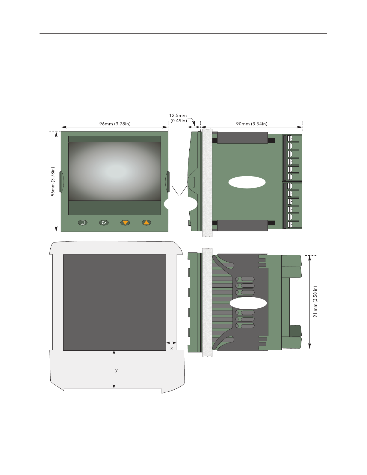
Figure 2 Mechanical installation details (standard case)
Panel cutout:
92mm x 92mm (both -0 + 0.8mm)
3.62in x 3.62in (both -0.00 + 0.03in)
Minimum inter-unit spacing:
Horizontal (‘x’) = 10mm (0.4in)
Vertical (‘y’) = 38mm (1.5in)
Side View
Top View
Latching
ears
A5E45696052A Rev-AA
Page 19
FEC920: USER GUIDE
Page 11
A
September 18
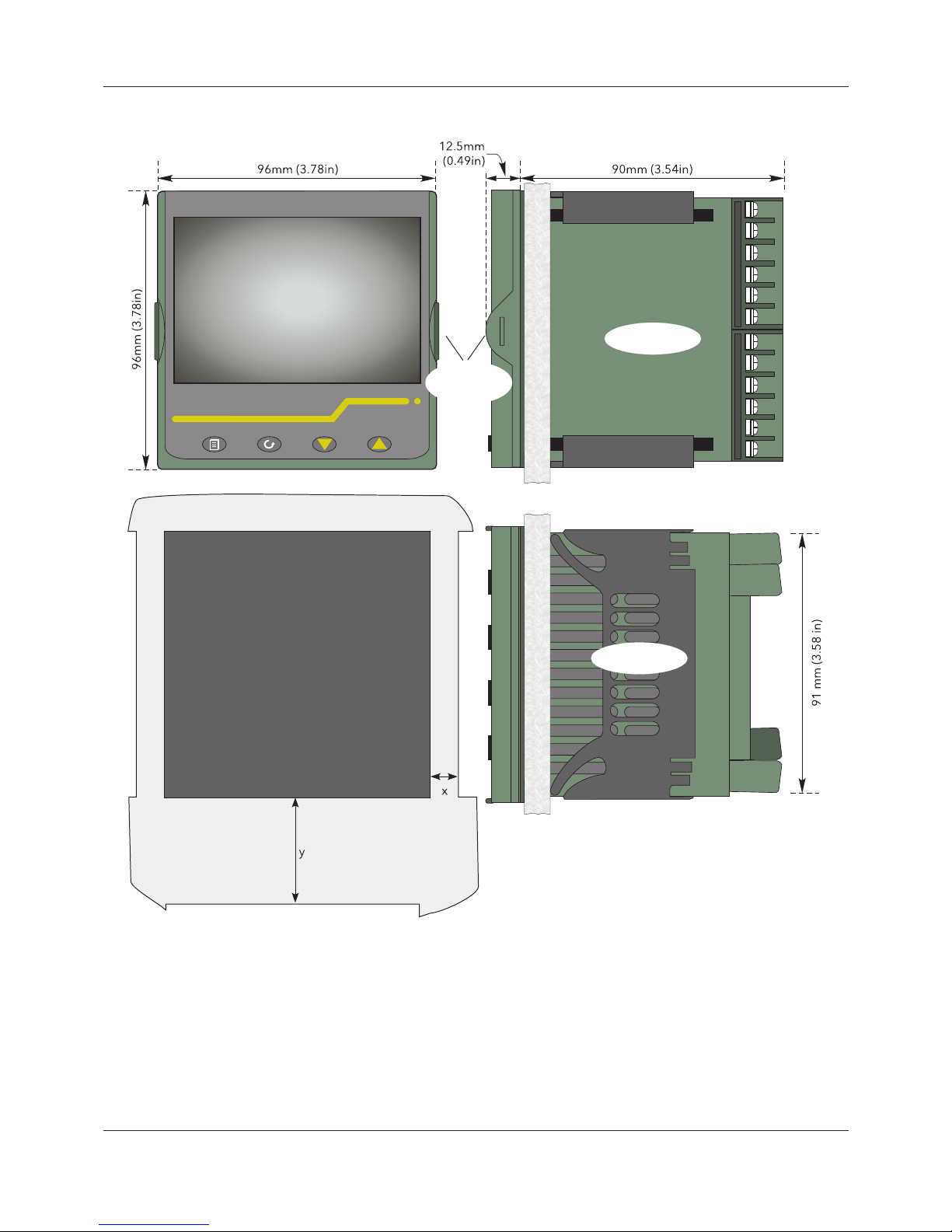
Figure 3 Mechanical installation details (wash down case option)
Panel cutout:
92mm x 92mm (both -0 + 0.8mm)
3.62in x 3.62in (both -0.00 + 0.03in)
Minimum inter-unit spacing:
Horizontal (‘x’) = 10mm (0.4in)
Vertical (‘y’) = 38mm (1.5in)
Side View
Top View
Latching
ears
A5E45696052A Rev-AA
Page 20

FEC920: USER GUIDE
Page 12
A
September 18
4.2 ELECTRICAL INSTALLATION
Figure 4 shows the locations of the various user terminations along with signal and supply wiring pinouts.
4.2.1 Termination details
The screw terminals accept single wires in the range 0.21 to 2.08mm2 (24 to 14 AWG) inclusive, or two wires
each in the range 0.21 to 1.31mm2 (24 to 16 AWG) inclusive.
Screw terminals should be tightened to a torque not exceeding 0.4Nm (3.54lb in).
A5E45696052A Rev-AA
Page 21

FEC920: USER GUIDE
Page 13
A
September 18
Figure 4 Connector locations and pinouts (rear panel)
8
1
mV
0 to 1V
0 to 10V
T/C
1R0≤R≤1k0
Supply
Voltage
Safety Earth
Brown
Blue
Each wire connected to
LA, LB and LC must be
less than 30m (98.43ft).
I/O1
Contact closure
O/P2
O/P3
Dig InA
Dig InB O/P4; O/P5
Relay output
Contact closure Relay outputContact closure
An In1; An In2; An In3; An In4
T/C, Volts, millivolts
RTD (two wire)
RTD (three wire)
Milliamps Digital
R<200R = active
R>350R = inactive
100 to 230Vac±15%;
48/62 Hz
24Vac; -15%, +10%
48 to 62 Hz or
24Vdc; -15%, +20%
(polarity irrelevant)
Isolated DC o/p (mA)
Ohms inputs
R>500R = inactive
R<150R = active
Relay output
Logic o/p (active high)
Isolated DC o/p (mA/V)
Internal Link (0V)
R>600R = inactive
R<300R = active
Relay output
Logic o/p (active high)
Isolated DC o/p (mA)
An In1; An In2; An In3; An In4
Dual mV/TC
Dual mA
Dual input option (Section 4.2.3, below)
(Primary and secondary inputs are not electrically isolated from one another.)
For maximum accuracy, it is recommended that separate returns are made to
the negative terminal.
Mains (Line) supply voltage
Low voltage option wiring
A5E45696052A Rev-AA
Page 22

FEC920: USER GUIDE
Page 14
A
September 18
4.2.2 Low Voltage Option
This option allows the use of a low voltage ac or dc 24V supply. The specification in Appendix A gives full details.
The polarity of the dc supply connection is not important - it may be connected either way round.
4.2.3 Dual Input Option
This is a cost option, enabled on a channel-by-channel basis by means of entering the relevant password in the
‘Feature3 Pass’ field in Instrument.Security menu described in Section 6.1.6.
For each enabled channel, a pair of thermocouple, mV or mA inputs can be connected to the instrument. These
inputs are called ‘primary’ and ‘secondary’, and are terminated at the analog input terminals (An In1 to An In 4)
as shown in Figure 4, above. The primary inputs 1 to 4 are assigned to channels 1 to 4, as normal. Each
secondary input must be soft wired to a maths channel configured as Operation = ‘Copy’ if it is to be recorded/
displayed/alarmed etc.
Soft wiring is described in Section 9.
Maths channels are described in Section 6.5.1.
Channel configuration is described in Section 6.4.1.
Input adjust is carried out as described in Section 6.1.9.
4.2.3.1 Sample Rate
For dual input channels, both primary and secondary sample rate is reduced to 4Hz (250ms) from the normal
8Hz (125ms).
4.2.3.2 Sensor Break Detection
Input sensor break detection is not supported for secondary inputs. The internal circuit acts as a ‘pull up’ on the
secondary input which therefore saturates high in the event of a sensor break.
4.2.3.3 Dual Milliamp Offset Correction
If ‘Dual mA’ is selected as input type, then an automatic offset correction will be made, according to the shunt
value entered in channel configuration. Refer to Section 6.4.1 for further information.
4.2.3.4 Input Range Limitation
There is no 10V range associated with the secondary input. Any input greater than +2V or less than -2V is
deemed to be ‘bad range’.
4.2.4 Modbus Master communications
The master instrument can be connected directly to up to two slaves using standard Ethernet network cable
either directly (single slave only) or via a hub or switch (one or two slaves). In either case, ‘straight through’ or
‘crossover’ cable may be used. The cable is terminated at the RJ45 socket at the rear of the unit.
4.2.5 EtherNet/IP
The Client and Server are connected in the same way as described above for Modbus Master communications,
except that there can be only one client and one server.
Note: Due to the nature of the input circuit, a large offset may appear for secondary thermocouple
inputs. This offset can be removed only by using the input adjust feature described in Section
6.1.9. Because of this offset, the dual thermocouple input option is not suitable for AMS2750D
applications.
A5E45696052A Rev-AA
Page 23

FEC920: USER GUIDE
Page 15
A
September 18
5 OPERATION
On power up a default or custom splash screen appears and remains visible whilst the unit is
initialising. If during this process a network broadcast storm is detected, the unit stops, displaying a
network failure icon until the broadcast storm has cleared, after which the initialisation process
resumes.
5.1 INTRODUCTION
The operator interface consists of a display screen and four push buttons.
5.1.1 Display Screen
The display screen is used both to display channel information (in one of a number of display modes), and to
display the various configuration screens which allow the user to setup the recorder to display the required
channels, to set up alarms and so on. Display modes are described in Section 5.4 below; configuration is
described in Section 6.
In display mode, the screen is split horizontally into three areas (Figure 5):
1. a faceplate giving channel details.
2. the main display screen showing channel traces etc.
3. the status area, displaying instrument name, the current time and date and any system icons.
Figure 5 Display mode screen (vertical trend)
In configuration mode, the entire display screen is devoted to the selected configuration menu.
5.1.2 Navigation Pushbuttons
Figure 6 Top level menu (Engineer level access)
There are four navigation buttons, called ‘Page’, ‘Scroll’, ‘Lower’ and ‘Raise’ located below the screen. The
general properties of these buttons are described in the remainder of this section, but some have additional,
context sensitive functions, which, for the sake of clarity are not described here but in the relevant sections (e.g.
‘Message summary’) of the manual.
12:01:08
Channel 1 6.23V
Instrument name
Faceplate
Main display screen
Status area
Home
Configuration
Go to View
Faceplate cycling (On)
Operator Notes
Demand Archiving
Log out
History
A5E45696052A Rev-AA
Page 24
FEC920: USER GUIDE
Page 16
A
September 18
PAGE BUTTON
From any non-configuration page, pressing this push button causes the top level menu (Figure 6) to appear.
The figure shows the menu for a user logged in with ‘Engineer’ level access. Other access levels may have
fewer menu items.
Within configuration pages, the Scroll button can be used as an enter key to select lower menu levels. In such
cases the page button is used to reverse this action, moving the user up one menu level per operation.
SCROLL BUTTON
From trending pages, operation of the scroll push-button scrolls through the channels enabled in the group. The
Faceplate cycling ‘Off’ selection can be used to keep a particular channel permanently displayed, and the scroll
pushbuttons can then be used to select channels manually.
In configuration pages, the scroll key operates as an ‘enter’ key to enter the next menu level associated with
the highlighted item. Once the lowest menu level is reached, operation of the scroll key allows the value of the
selected item to be edited by the relevant means (for example, the raise/lower keys, or a keyboard entry).
The ‘Page’ key is used to move the user back up the menu structure, until the top level menu is reached, when
the scroll key can be used again to return to the Home page.
The scroll button is also used to initiate user wiring as described in Section 9.
RAISE/LOWER BUTTONS
Within trending displays, the Raise and Lower keys can be used to scroll through the enabled display modes in
the sequence: vertical trend, horizontal trend, vertical bargraph, horizontal bargraph, numeric, vertical trend,
and so on.
Within configuration pages, these pushbuttons act as cursor keys, allowing, for example, the user to highlight
menu items for selection using the scroll button, and in many cases allowing the user to select one from a number of alternative values within menu items. These keys are also used to navigate through the virtual keyboards
(Section 5.6) and number pads used to enter text or numeric strings.
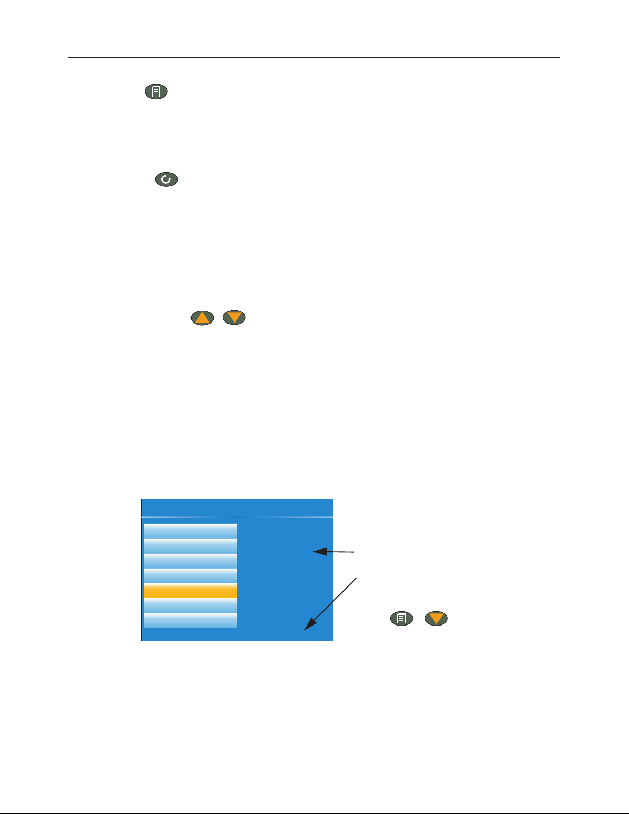
5.1.3 On Screen Help
The top level configuration menu includes contextual help text on the right-hand half of the screen. Mostly this
text fits within on screen height. Where this is not the case, the text can be moved up or down the screen by
holding the Page button operated whilst using the up and down arrows to move the text.
The down arrow moves the text upwards on the screen; the up arrow moves it downwards.
Figure 7 On-screen help (typical)
Select configuration menu
Logic (2 Input)
Logic (8 input)
Multiplexer
Math (2 input)
Timer
User values
Alarm Summary
The timer function block
offers a universal timer
which may be
re-configured between
single pulse outputs
and re-triggering
outputs. Timer types
are:
On pulse on-timer
On-screen help.
(Use the Page button with the
down arrow to access hidden
text at the bottom of the screen)
+
A5E45696052A Rev-AA
Page 25

FEC920: USER GUIDE
Page 17
A
September 18
5.2 PROCESS VARIABLE DISPLAY
As discussed above, the operator interface consists of a display screen and associated push buttons. The
display screen shows process variables in one of a number of formats, or operational details (notes or alarm
history for example), or configuration details for use in setting up the recorder to produce the required displays
and history formats. The remainder of this section discusses the process variable displays, alarm displays and
so on; configuration details are to be found in Section 6.
Figure 8 depicts a typical trend display and gives details of the various areas of the display page.
Figure 8 Typical display screen (Vertical trend)
Figure 8 shows a vertical trend page. Operating the Raise/Lower push-buttons allows the user to scroll through
the other display modes: Horizontal trend, Vertical bargraph, horizontal bargraph, numeric, vertical trend, and
so on. All these display modes are described in Section 5.4, below.
A display mode can also be selected from the Top level menu ‘Go To View’ item which appears when the ‘Page’
key is operated.
The scroll button can be used to scroll through the points in the group, overriding the ‘Faceplate Cycling’ on or
off selection
5.2.1 Alarm Icons
The alarm icons shown below appear in some display modes. The icons on a channel faceplate show the status
of that channel’s alarm(s), as follows:
Icon is flashing alarm is active but unacknowledged or it is an Auto alarm which is no longer active
but which has not been acknowledged.
Icon steadily illuminated the alarm is active and has been acknowledged.
Alarm thresholds and deviation alarm bars appear for horizontal and vertical trend modes. For deviation bars,
the bar stretches from (Reference - Deviation) to (Reference + Deviation). Vertical and Horizontal bargraph
modes display only absolute alarm symbols.
Note: Some of the items below can be selected for use only by users with a suitable permission
level as set up in the ‘Instrument’ ‘Security’ menu described in Section 6.1.6.
Note 1: A full discussion of alarms is given in the Channel Configuration section of this manual,
Section 6.4.3.
Note 2: Trigger alarms do not display threshold marks or bars, or faceplate symbols.
12:01:08
Channel 1 6.23V
Inst name
Current time/date
Current point value and units
Current point ‘pen’
Current point scale
Time/date stamps
Current point name
Recording status
Instrument name
A5E45696052A Rev-AA
Page 26

FEC920: USER GUIDE
Page 18
A
September 18
Figure 9 Alarm icons
5.2.2 Status Bar Icons
The following items can appear in a dedicated window immediately to the left of the time and date, at the bottom
right-hand corner of the display. The width of this window expands as the number of icons increases, and the
instrument name is truncated, as necessary, to make room.
SYSTEM ALARMS
This indicator appears, flashing, if any one or more of the alarms listed below is active. The System Alarms
summary page (accessed from ‘Go to View in the top level menu) allows the user to view such system alarms
as are active. It is not possible to ‘acknowledge’ system alarms.
Archive Disabled An unattended archiving strategy has temporarily been disabled.
Archiving Failed An unattended archiving strategy has failed to complete.
Archiving Timeout A configured archiving strategy has timed out.
Battery failure Indicates that the battery is approaching the end of its useful life, or that
it is missing or is completely exhausted. Immediate battery replacement
is recommended (Appendix B, Section B1).
Broadcast Storm detected Networking is limited until the storm has passed.
Clock failure The internal clock was found to be corrupt at power up, or that the time
has never been set. Time is forced to 00:00 1/1/1900. Can be caused
by battery failure, in which case a battery failure message appears. The
error is cleared by setting the time and date.
Channel error Indicates a hardware failure in the channel circuit or in the internal cold
junction temperature measurement.
Database failure Corrupted EEPROM or flash memory.
DHCP Server failure For units with ‘IP Type’ set to ‘DHCP’ (Network.Interface configuration)
this alarm occurs if the instrument is unable to obtain an IP address from
the server.
FTP Archiving file lost A file has been deleted that had not yet been archived. Possible causes:
Communications with the server could not be established,; archive is
disabled; archive rate too slow.
FTP Archiving too slow The archive rate is too slow to prevent the internal memory from
overflowing. The recorder effectively switches to ‘Automatic’
(Section
6.2.2) to ensure that data is not lost.
Absolute High
Absolute Low
Deviation High
Deviation Low
Deviation Band
Rising Rate of change
Falling Rate of change
Digital High
Digital Low
A5E45696052A Rev-AA
Page 27

FEC920: USER GUIDE
Page 19
A
September 18
FTP Primary Server Failure This error occurs if the recorder fails to establish connection with the
primary server, after two attempts. After the second attempt fails, the
recorder attempts to establish connection with the secondary server
instead. Primary and secondary server details are entered in the
Network. Archiving area of configuration (Section 6.2.2).
FTP Secondary Server Failure This error occurs if the recorder fails to establish connection with the
secondary server, after two attempts. Primary and secondary server
details are entered in the Network.Archiving area of configuration
(Section 6.2.2).
Maths channel failure Appears if, for example, the divisor of a divide function is zero.
Media archiving file lost A file has been deleted that had not yet been archived. Possible causes:
memory stick missing, full or write protected; archiving has been
disabled; archiving rate too slow.
Media archiving too slow The archive rate is too slow to prevent the internal memory from
overflowing. The recorder effectively switches to ‘Automatic’ (Section
6.2.2) to ensure that data is not lost.
Media full Archive storage device is full. The alarm becomes active only when an
archive is in progress.
Media missing No archive storage device present when archive attempted.
Non-volatile memory failure RAM copy of non-volatile parameters is corrupted.
Non-volatile Write Frequency warning
One or more parameters are being written frequently to non-volatile
memory. If this continues, it may lead to ‘memory depletion’ (i.e. the
memory will no longer be able to store values correctly). A common
cause of this problem is frequent writes over Modbus comms.
Recording failure (message) Message explains reason for failure.
SNTP failure Invalid data received from SNTP server, for example, the year received
from the server is <2001 or >2035, or the server cannot be accessed.
Time synchronization failure Instrument time has failed to synchronize with SNTP server.
If more than 5 ‘Time change events’ occur within 24 hours a ‘Time
synchronization failure’ alarm is set. The alarm occurs 24 hours after
the first event. Once synchronization is re-established, the alarm self-
clears within 24 hours. A ‘Time change event’ occurs whenever the
recorder time is found to be more than two seconds different from the
server time. If the instrument time differs from the SNTP time by less
than two seconds, the instrument time is updated gradually (1ms, eight
times a second) to prevent time changes being recorded.
SNTP time is based on elapsed seconds since 00:00 hours on 1st
January 1900. The time is not affected by time zones or daylight saving
adjustments.
USB overcurrent USB power fault - too much current (i.e. >100mA) is being drawn by a
USB device.
Wiring failure The user wiring has failed to verify, i.e. one or more wires has been
detected that does not have both a source and a destination defined.
This may be the result, for example, of power loss during a download
from iTools.
A5E45696052A Rev-AA
Page 28

FEC920: USER GUIDE
Page 20
A
September 18
CHANNEL ALARM
This indicator appears if any channel (including channels not in the display group) is in an alarm state. The
symbol is illuminated continuously if all alarms are acknowledged or flashes if any one or more alarms is
unacknowledged. Alarms are acknowledged from the Root menu ‘Alarm summary’ item as described in Section
5.3.3 or in the Channel configuration area (Section 6.4.3) if the user’s access permission is appropriate.
USB
This icon appears whenever a memory stick (max. capacity 8GB) or other supported USB device (Section 11)
is plugged into the USB port at the rear of the recorder.
When data transfer is in progress between the instrument and the memory stick, the icon changes to a ‘busy’
version.
FTP ICON
The FTP icon appears whenever transfer activity is taking place.
RECORD ICON
One of four icons appears at the bottom left corner of the display to indicate recording status.
Record
This indicates that the recorder is recording the items selected in the Group Recording area of configuration
(Section 6.3).
Stopped
This means that ‘Enable’ has been set to ‘no’ in the Group Recording area of configuration (Section 6.3).
Trending is not affected.
Paused (Suspended)
This means that recording has been paused by a wire to the Suspend parameter (Group Recording area of
configuration
(Section 6.3) going true (high). Trending is not affected.
In Configuration
The recorder has been placed in configuration mode either at the user interface, or via iTools. Recording is
stopped until the recorder is no longer in configuration mode. For each non-recording state (Stopped, Paused
or In Configuration). A new history file is created when the unit comes out of configuration mode.
MESSAGE ICON
This ‘envelope’ icon appears when a message is generated and it remains on display until the Message
Summary (see Message Summary on page 24) is accessed, when it is removed from the display until the next
new message is generated.
AUTOTUNE ICON
For instruments fitted with the Loop option, this symbol appears during the Autotune process.
Caution: The Memory stick must not be removed while archiving
(demand or automatic) is in progress, as to do so may
irreparably damage the file system of the memory stick,
rendering it unusable. It is recommended that all archiving is
suspended before the memory stick is removed.
Note: For recording to be enabled, configuration status must be ‘logged out’ both at the instrument
and at iTools.
Memory
stick fitted
Transfer in
progress
A5E45696052A Rev-AA
Page 29

FEC920: USER GUIDE
Page 21
A
September 18
5.2.3 Breaks in recording
Breaks in recording can be caused by the unit being powered down, by the user entering configuration mode
or when the recorder time is changed manually. In vertical and horizontal trend modes, a line is drawn across
the width/height of the chart to indicate that recording has been interrupted.
On power up, a red line is drawn across the chart. In ‘History’, if messages are enabled the message:
Date Time System power up
is printed on the chart, together with the configuration and security revisions.
On exiting configuration mode, a blue line is drawn on the chart and in ‘History’, if messages are enabled, the
messages:
Date Time Logged out.
Date Time Config Revision: N was N-1 (assuming a configuration change was made)
Date Time Logged in as: Engineer
appear on the chart.
When the instrument time is changed (manually - not through daylight saving action) a green line is drawn on
the chart and in ‘History’, if messages are enabled, the message:
Date Time Time/Date changed
appears on the chart.
5.3 TOP LEVEL MENU
This menu appears when the page key is operated from any non-configuration page. The menu items displayed
depend on the access permission of the user. One of the menu items is highlighted, and if the scroll key is
operated, then it is the highlighted item that is ‘entered’.
Figure 10 shows the top level menu for Engineer level access.
Figure 10 Top level menu
5.3.1 Home
Operating the scroll key whilst ‘Home’ is highlighted causes a return to the ‘Home’ page. By default, this is the
vertical trend mode, but the mode can be changed in ‘Instrument.Display’ configuration (Section 6.1.3).
5.3.2 Configuration
Operating the down arrow key highlights the ‘Configuration’ item. Operating the Scroll key enters the
configuration submenu described in Section 6.
Note 1: ‘Configuration’ appears only if the user has an appropriate access level.
Note 2: If the Auditor feature is enabled, additional user accounts are available. If one of these
users are logged in, the ‘Configuration’ menu option is replaced by the ‘User’ menu option
instead (see Section 5.3.2.1).
Section 5.3.1
Section 5.3.2
Section 5.3.3
Section 5.3.4
Section 5.3.5
Section 5.3.6
Section 5.3.7
Section 5.3.8
Home
Configuration/User
Go to View
History
Faceplate cycling (On)
Operator Notes
Demand Archiving
Log out
Page key
Scroll key
A5E45696052A Rev-AA
Page 30

FEC920: USER GUIDE
Page 22
A
September 18
5.3.2.1 User menu
If the Auditor feature is enabled, up to 25 additional user accounts are available with configurable access
permissions and passwords. If one of these users are logged in, the ‘Configuration’ menu option is replaced by
a ‘User’ menu option which provides the ability for the user to change their password and set the Archive Interval
(if the user has appropriate permissions).
Operating the scroll key whilst the ‘User’ item is highlighted, displays the individual user account menu, as
shown in the following figure. The menu title matches that of the username used to log in.
Figure 11 User menu
Password Allows the user to change their password (up to a maximum of 20 characters). The
minimum password length can be configured using the Min Password Len parameter in
the Security menu (see Section 6.1.6).
Archive Rate Allows the user to specify the frequency at which the contents of the flash memory are
archived to the USB port, or via FTP to a PC. Scrollable settings are:
None: Automatic archiving is disabled. Any archiving must be initiated by the user
using Demand Archiving.
Minute: Archive is initiated on the minute, every minute.
Hourly: Archive is initiated at 00:00 each day.
Weekly: Archive is initiated at midnight every Sunday.
Monthly: Archive is initiated at 00:00 on the 1st of every month.
Automatic. The recorder selects the least frequent of the above archive periods which is
guaranteed not to lose data as a result of the internal flash memory running
out of space.
This field is editable if the logged in user has appropriate permissions to adjust the archive
interval (see Section 6.1.11). For further information on archiving, refer to Section 6.2.2.
**********
None
Password
Archive Rate
User account 12
A5E45696052A Rev-AA
Page 31

FEC920: USER GUIDE
Page 23
A
September 18
5.3.3 Go to View
Operating the scroll key whilst the ‘Go to view’ item is highlighted, calls the Go to view submenu (Figure 12).
This allows the user to view channel alarms, system alarms, messages or to select a different display mode.
Figure 12 Go to view submenu
ALARM SUMMARY
For each active alarm, this page displays the channel identifier with alarm number (e.g. C1(2) = channel 1; alarm
2), the channel descriptor, the alarm threshold the current process value and an alarm type symbol.
To return to the top level menu, operate the Page key.
Figure 13 Alarm summary page with acknowledge confirmation display
Note 1: If an option is not fitted, its display mode does not appear in the list.
Note 2: Some display modes must be enabled in Instrument.View configuration (Section 6.1.3)
before they become available.
Note 1: The background color to the channel ID is the same as that chosen for the channel.
Note 2: A prefix ‘C’ in the channel ID means that this is a measuring channel; A prefix ‘V’ means that
this is a virtual channel (i.e. a totalizer, counter or maths channel.
Alarm Summary
System Alarms
Message Summary
Vertical Trend
Horizontal Trend
Vertical Bargraph
Horizontal Bargraph
Numeric
Alarm Summary
System Alarms
Message Summary
Vertical Trend Mode
Horizontal Trend Mode
Vertical Bargraph Mode
Horizontal Bargraph Mode
Numeric Mode
Alarm Panel Mode
Modbus Master display mode
Dual Loop
Modbus Master display mode
EtherNet/IP display mode
Alarm Panel
Control
Control (Dual Loop)
Modbus Master
EtherNet/IP
Alarm Summary
Furnace 1 temp 1 798.39750.00C1(2)
Furnace 1 temp 3 763.89750.00C2(1)
Furnace 1 temp 2 603.39590.00C3(1)
Furnace 2 temp 1 630.71645.00C4(1)
Channel ID
(Alarm number)
Page key
Scroll key
Channel descriptor
Alarm Threshold
Channel current process value
Alarm Type indicator
A5E45696052A Rev-AA
Page 32

FEC920: USER GUIDE
Page 24
A
September 18
ALARM ACKNOWLEDGEMENT
To acknowledge an alarm from this view:
1. Use the up and down arrows to highlight the required
alarm.
2. Operate the scroll button. The ‘Acknowledge alarm’
window appears.
3. Use the up arrow to highlight the relevant field (C2(1) in
this example), or ‘All’ if all alarms are to be
acknowledged.
4. Operate the scroll key to confirm. If the alarm fails to
respond, this may be due to the fact that it has been configured as a ‘Manual’ alarm, and the trigger has
not yet returned to a ‘safe’ (non-alarm) state, or it could be that the instrument is in a logged out state.
SYSTEM ALARMS
Operating the scroll button whilst the ‘System Alarms’ field is highlighted displays a list of all currently active
system alarms. Section 5.2.2 contains a list of system alarms and their interpretations. To return to the top level
menu, operate the Page key.
A further operation of the scroll button displays a ‘Help Information’ page, giving the reason for the highlighted
alarm.
Operate the scroll button again to return to the system alarm display.
MESSAGE SUMMARY
Operating the scroll key whilst the ‘Message summary’ field is highlighted displays the ten most recent
messages.
Operating the scroll key whilst a message is highlighted shows the selected message in more detail (and using
the up/down keys allows the other messages to be scrolled through). Whilst in this mode, operating the scroll
key again, allows the user to choose to jump to the message’s location in trend history mode (Section 5.5) or
to return to the summary page.
By default, the interface is set up such that:
1. all message types are included.
2. the up and down arrow keys cause the highlighted selection to move up or down by one message at a
time.
Alarm Summary
Furnace 1 temp 1 763.26750.00C1(2)
Furnace 1 temp 3 770.01750.00C2(1)
Furnace 1 temp 2 595.83590.00C3(1)
Furnace 2 temp 1 644.33645.00C4(1)
Acknowledge alarm?
Acknowledge alarm?
No C2(1) All
No C2(1) All
A5E45696052A Rev-AA
Page 33

FEC920: USER GUIDE
Page 25
A
September 18
Figure 14 Message summary features
MESSAGE FILTERS
All Messages Causes all messages to be displayed on the screen.
System Shows only system alarms.
Alarm Shows only channel alarms.
Power up Shows only power up messages.
Login/out Limits the display to Log in and Log out events.
20/11/09 08:06:37 Inactive: Ch1(Al1)
20/11/09 08:06:29 Active: Ch2(Al1)
20/11/09 08:06:22 Active: Ch1(Al1)
20/11/09 08:06:19 Inactive: Ch2(Al2)
20/11/09 08:06:18 Inactive: Ch1(Al2)
20/11/09 08:06:09 Inactive: Ch2(Al1)
20/11/09 08:06:01 Active: Ch1(Al2)
20/11/09 08:05:59 Active: Ch2(Al1)
20/11/09 08:05:22 Battery flat less than 5%
Message Summary (All Messages)
20/11/09 08:05:22
Battery flat less than 5% remaining
All Messages
Refresh
Exit Messages
Use scroll button to scroll through ‘All
Messages’, ‘System’, ‘Alarm’ and ‘Power Up’.
Use page button to confirm selection.
Use scroll button to return to refreshed
Message Summary page.
Use the scroll or page button to return to the top
level menu.
9/47
Go to?
Summary History
To Trend History
display (Section 5.5)
A5E45696052A Rev-AA
Page 34

FEC920: USER GUIDE
Page 26
A
September 18
DISPLAY MODE SELECTION
Use the up/down arrow buttons to highlight the required display mode.
Once the required display mode is highlighted, operation of the scroll
button causes the recorder to leave the ‘Go to View’ menu and to display
channel values in the selected mode. See Section 5.4 for a description of
the various display modes.
Alternatively the up and down arrow buttons can be used from any of the
display modes to cycle through the available modes in the order listed in
the figure.
5.3.4 History
This top level menu item allows the user to switch from real-time trending to review mode, where channel values, messages, alarm triggers, etc. can be viewed back as far as the last significant configuration change. History mode is fully discussed in Section 5.5.
5.3.5 Faceplate Cycling on/off
For the purposes of this document the channel whose faceplate is currently displayed and whose ‘pen’ symbol
is visible is called the ‘Active’ channel.
By default, the recorder scrolls through all the channels in the display group, with each channel becoming the
active channel in turn. This top level menu ‘Faceplate Cycling’ item allows the user to inhibit this scrolling action
such that the currently active channel remains active permanently, or until a manual scroll is performed using
the scroll button (or until Faceplate Cycling is re-enabled).
‘Faceplate Cycling’ is highlighted by using the up/down arrow buttons. Once highlighted, the status can be
changed from ‘On’ to ‘Off’ or vice-versa using the scroll button. Operation of the ‘Page’ button returns to the
trend display.
5.3.6 Operator Notes
This area allows up to 10 notes to be created when logged in as Engineer, using either the text entry techniques
described in Section 5.6, or ‘iTOOLS’ described in Section 9. Once logged out, operating the scroll button whilst
a note is highlighted calls a selection box allowing the user either to send that note to the chart, or to write a
Custom Note.
CUSTOM NOTE
The Custom Note is written using the text entry techniques described in Section 5.6. Once the note is complete,
operation of the page button calls a confirmation display. The down arrow is used to highlight ‘Yes’, and when
the scroll key is then operated, the message is sent to the chart. The user name is added to the start of the
custom note when saved. This custom note is not retained for further use, so if it is required on a regular basis,
it is suggested that one of the Operator Notes 1 to 10 be configured (Engineer access level required) so that it
may be used instead.
5.3.7 Demand Archiving
This allows a user, with a high enough access level, to archive a selected portion of the recorder history, either
to a ‘memory stick’ plugged into the USB port at the rear of the recorder (Local Archiving), or to a PC, by means
of the FTP protocol (Remote Archiving). The archived data remains in the flash memory of the instrument. When
the flash memory is full, new data causes the oldest file(s) to be discarded.
The up and down arrow keys are used to navigate to the required field.
Note 1: If an option is not fitted, its display mode is not
available for selection.
Note 2: Some display modes must be enabled in Instrument.
Display configuration (Section 6.1.3) before they
become available.
Note: Each note can contain up to 100 characters.
Alarm Summary
System Alarms
Message Summary
Vertical Trend
Horizontal Trend
Vertical Bargraph
Horizontal Bargraph
Numeric
Alarm Panel
Control
Modbus Master
EtherNet/IP
A5E45696052A Rev-AA
Page 35

FEC920: USER GUIDE
Page 27
A
September 18
ARCHIVE MENU
Figure 15 Demand Archiving menu (Local Archiving on left; Remote Archiving on right)
Archive To With this item highlighted, the scroll button and the up/down arrows can be used to select
‘USB’ or ‘FTP Server’.
For ‘USB’, the archive will be made to the rear USB memory stick. For ‘FTP Server’ the
archive will be made to the Primary or Secondary server (configured in the
Network.Archive area of configuration described in Section 6.2.2. For more details about
remote archiving, see ‘Remote archiving’, below.
Archive In a similar way, select the archive period:
None: No archiving to take place. (Not editable when logged out).
Last Hour: Archives all files created within the last 60 minutes.
Last Day: Archive all files created in the last 24 hours.
Last Week: Archives all files created in the past seven days.
Last Month: Archives all files created in the past 31 days.
Archive All: Archives all the files in the recorder’s history.
Bring To Date: Archives all files created or updated since the ‘Last Archive’ date and time.
Suspend Schedule When set to ‘Yes’, automatic (scheduled) archiving is stopped, once the transfer of the
current file is complete. Suspend Schedule must be set to ‘No’ again, to restart the
suspended archive. Suspend can be used to allow the memory stick to be removed and
re-fitted safely.
Cancel All When set to ‘Yes’, this cancels USB archiving activity immediately, or cancels FTP
archiving once transfer of the current file (if any) is complete.
Last Archive Shows the date and time at which the last archive (demand or automatic) was attempted.
If a demand archive is requested, or is in operation when an automatic archive is triggered,
the automatic archive takes precedence.
Status For Archive to USB only:
‘Complete’ means that no archiving is currently taking place.
‘Transferring’ indicates that an archiving is in progress. Accompanied by an animated
circular display.
‘Suspended’ means that archiving has been suspended as requested.
PriStatus For Archive to FTP Server only, this shows the transfer status between the instrument and
the primary host computer.
SecStatus For Archive to FTP Server only, this shows the transfer status between the instrument and
the secondary host computer.
FTP SERVER ARCHIVING
This allows the archiving of recorder files to a remote computer via the RJ45 type connector at the rear of the
recorder, either directly or via a network.
In order to carry out a successful transfer:
1. Details of the remote host must be entered in the Network.Archive area of configuration (Section 6.2.2).
Demand Archiving
Archive To
Archive
Suspend Schedule
Cancel All
Status
Last Archive
USB
None
No
No
Complete
02/11/2011 11:37:09
Demand Archiving
Archive To
Archive
Cancel All
Pri Status
Sec Status
Last Archive
FTP Server
None
No
Complete
Connecting
02/11/2011 11:37:09
A5E45696052A Rev-AA
Page 36

FEC920: USER GUIDE
Page 28
A
September 18
2. The remote computer must be set up as an FTP server. Help from the user’s IT department may be
necessary in order to achieve this. Appendix B, Section B2 to this manual suggests one way, using
Filezilla.
3. The remote computer must also be set up to respond to ‘pings’. This is because the instrument pings the
host whilst establishing connection, and if it does not receive a response the archive attempt fails.
When accessing files using Microsoft® Internet Explorer, the address (URL) field can be in one of two formats:
1. ftp://<instrument IP address>. This allows a user to log in as the anonymous user (if the recorder has any
account with the user name set to ‘anonymous’ with a blank password.
2. ftp://<user name>:<password>@<instrument IP address> to log in as a specific user.
Microsoft® Internet Explorer displays, by default, history files only. To quit the history folder, either uncheck the
Tools/Internet Options/Advanced/Browsing/’Enable folder view for FTP sites’ option, or check the Tools/Internet
Options/Advanced/Browsing/’Use Web based FTP’ option.
REVIEW SOFTWARE
‘Review’ is a proprietary software package which allows the user to extract ‘archive’ data from one or more
suitable instruments* and to present this data on a host computer, as if on a chart, or as a spreadsheet. The
host computer must be set up as an FTP server (see Appendix B, Section B2 for a description of one way of
doing this).
As described in the Review help system, ‘Review’ allows the user to set up a regular transfer of data (using
FTP) from connected instruments into a database on the PC, and then from this database to the chart or
spreadsheet. The chart/spreadsheet can be configured to include one or more ‘points’ from one or all connected
instruments (where a ‘point’ is an umbrella term for channel, totalizer, counter etc.).
It is also possible to archive instrument history files to a memory stick, Compact Flash card etc. (depending on
instrument type) and to use this to transfer the data to the PC.
Each type of instrument has its own remote user name and password configuration - for this instrument, the
user name and password are both ‘history’.
*Suitable instruments are connected instruments, the archive files of which have the suffix ‘.uhh’.
5.3.8 Login
Login allows the user to enter a password in order to gain access to areas of the unit’s configuration which are
not available when the user is logged out.
Passwords can be assigned to the Supervisor and Engineering level accounts, and it is recommended these
be set with a strong password that is difficult to guess. Passwords are also assigned to the additional 25 user
accounts is the Auditor feature is enabled. Failed login attempts are recorded in the history.
LOGGED OUT ACCESS LEVEL
Logged out mode allows the user to select viewing mode, to view history, to view alarms, to toggle faceplate
cycling on and off, to send notes, to suspend/resume USB archiving and to access the login process.
A5E45696052A Rev-AA
Page 37

FEC920: USER GUIDE
Page 29
A
September 18
OPERATOR ACCESS LEVEL
In addition to the logged out features, Operator access level allows the user to acknowledge alarms, to edit
notes and to perform demand archive operations.
By default, no password is required in order to enter Operator level, but a password can be set either at
Supervisor level or at Engineer level.
If the Auditor feature is enabled, the Operator user is disabled and instead replaced by the 25 User accounts
(see section User Access Level below). However, the User 1 account defaults to a user with a user name of
“Operator” in this instance (with no additional permissions), which can be kept, disabled, modified or overridden
if necessary or desired.
SUPERVISOR ACCESS LEVEL
In addition to the logged out level function, this access level allows the user to view the recorder’s configuration,
and to edit some values (such as alarm thresholds). By default, the default password for the Supervisor level is
‘100’ and this password can be changed in the Instrument area of configuration, either at Supervisor level or at
Engineer level.
When the Auditor feature is enabled, it is regarded as best practise that the Supervisor level is not used at all,
or, at the very least, locked down with a strong password. This can be enforced by disabling the Supervisor level
altogether (refer to the ‘Sup Log Disabled’ parameter in Section 6.1.6). With the Supervisor disabled, only the
Engineer level can view (and change) the instrument’s configuration.
ENGINEER ACCESS LEVEL
This allows full access to all areas of the recorder configuration. The default password is 100, but this can – and
should – be edited in the Instrument area of configuration (Section 6.1.5). It is recommended that a strong
password be used.
If the Auditor feature is enabled, it is recommended to only use the Engineering level within the context of a
formal change control procedure.
USER ACCESS LEVEL
If the Auditor feature is enabled, an additional 25 user accounts are available which can be configured to provide
customisable levels of permission on a per-account basis. When this is done, the standard Operator Access
Level is disabled, and the Logged Out user has no permissions. When logging in as one of these 25 user
accounts, the account number (1 to 25) is prefixed to the user name. Refer to Section 6.1.11 for details on how
to configure these user accounts and the permissions available to be assigned to each. Failed login attempts
are written to the history, as is the user being disabled if a maximum number of failed login attempts is
exceeded.
LOGIN PROCEDURE
From the top level menu, use the up or down arrow keys as often as necessary in order to highlight ‘Login’, and
then operate the Scroll key to produce the ‘Access Logged out’ display.
Note: Recording is stopped for as long as the user is logged in at Engineer
level, even if the recorder is not being configured. This is indicated by
the Record icon at the bottom left corner of the process value display
screen being replaced by the Configuration (wrench) icon.
Note: This procedure describes how to login to an access level with a password associated with it.
For non-password protected logins, the user needs only to select the required access level,
and press the scroll key.
Record icon
Configuration
icon
A5E45696052A Rev-AA
Page 38

FEC920: USER GUIDE
Page 30
A
September 18
Figure 16 Log in Menu
To log in as Engineer (default password = 100):
1. Operate the up arrow key three times, to display ‘Engineer’.
2. Press the scroll key to call the ‘alpha’ keyboard, with the letter ‘q’ highlighted.
3. Use the down arrow key three times to highlight ‘Numeric’.
4. Operate the scroll key to display the numeric keyboard (numeral ‘1’ highlighted.)
5. Operate the scroll key to enter ‘1’, then use the up arrow key nine times to highlight numeral ‘0’ and use
the scroll key twice to enter ‘0’ 0’, completing the password of 100.
6. Use the Page key to call the confirmation display.
7. If the password entry is as required, use the up arrow twice (or the down arrow once) to highlight the word
‘Yes’ and operate the scroll key to confirm. The top level configuration menu appears. Otherwise, ‘Cancel’
can be used to clear the entry in order to start again, or ‘No’ can be used to quit login.
5.4 DISPLAY MODES
The following subsections describe the various display modes available to the user. By default, the ‘Home’
display mode is ‘Vertical Trend’, but this can be edited as a part of ‘Instrument.Display’ configuration (Section
6.1.3). This configuration area also allows the user to disable one or more display modes should they not be
required.
The current display mode can be chosen either by using the top level menu ‘Go to View’ item or, from any
display mode, by scrolling through the enabled modes using the up or down arrow buttons.
Details of the various display modes are to be found in the following subsections:
Access
Access
Logged out
Operator
Access Supervisor
Access Engineer
Access Engineer
Password
Password
Password
Accept changes
No YesCancel
Access
<User>
* If the Auditor feature is enabled,
the Operator user is not displayed. If
the Auditor feature is not enabled,
the <User> user is not displayed.
*
*
Vertical trend ................................... Section 5.4.1
Horizontal trend
............................... Section 5.4.2
Vertical bargraph
............................. Section 5.4.3
Horizontal bargraph
......................... Section 5.4.4
Numeric ........................................... Section 5.4.5
Alarm panel
..................................... Section 5.4.6
Modbus Master
................................ Section 5.4.7
EtherNet/IP
...................................... Section 5.4.8
A5E45696052A Rev-AA
Page 39

FEC920: USER GUIDE
Page 31
A
September 18
5.4.1 Vertical Trend Mode
In this mode, channel values are traced as though on a chart rolling downwards (i.e with the latest data at the
top). The chart speed, and the number of major divisions are configured in the ‘Group.Trend’ area of
configuration (Section 6.3.1). By default, the chart background is black, but this can be changed to white or gray
in the ‘Instrument’ ‘Display’ area of configuration (Section 6.1.3).
Figure 17 Vertical trend mode display elements
One of the channels is said to be the ‘current’ or ‘scale’ channel. This channel is identified by its pen icon being
displayed, and by the channel descriptor, dynamic value and its scale being displayed on a ‘faceplate’ across
the width of the display, above the chart.
Each channel in the Group becomes the ‘current’ channel in turn, for approximately five seconds -i.e. the
channels are cycled through, starting with the lowest numbered channel. Once the final channel in the Group
has been displayed for five seconds, the first channel is returned-to and the process repeats. This scrolling
behavior can be enabled/disabled from the top level menu ‘Faceplate Cycling (Off)’ item described in Section
5.3.5.
The scroll button can be used to cycle through the channels manually in both Faceplate cycle on and off modes.
Use of the up arrow button causes the next enabled display mode to be entered (default = horizontal trend).
The page key calls the top level menu.
12:01:08
Channel 1 6.23V
Inst name
Alarm Threshold
Current point name
Current point scale
Current trace ‘pen’
Faceplate
Current point value
Time/date stamp
Current time/date
Recording symbol
Status icons
Instrument name
A5E45696052A Rev-AA
Page 40

FEC920: USER GUIDE
Page 32
A
September 18
5.4.2 Horizontal Trend Mode
This view is similar to the vertical trend mode described in Section 5.4.1 above, except that the traces are
produced horizontally rather than vertically. Initially, as each channel appears, its scale appears at the left edge
of the display (as shown below), but in order to show the maximum amount of trend data, the scale is overwritten
after a few seconds.
Figure 18 Horizontal trend display mode
Use of the up arrow button causes the next enabled display mode to be entered (default = vertical bargraph).
Use of the page key calls the top level menu.
5.4.3 Vertical Bargraph Mode
This display mode shows the channel values as a histogram. Absolute alarm threshold values appear as lines
across the bars, gray if the alarm is not triggered; red if the alarm is triggered. Alarm symbols appear for active
alarms.
Bargraph widths for four to six channels divide the width of the display screen equally between them. For one
and two channels, the width is fixed, and the bars are centred on the screen. Figure 19 shows some examples
(not to the same scale).
Figure 19 Vertical bargraph display mode
Use of the up arrow button causes the next enabled display mode to be entered (default = horizontal bargraph).
Use of the page key calls the top level menu.
Note: Timestamps appear to the right of the gridline to which they relate.
Inst name
Channel 1
6.23
V
By default, after a few seconds, the
‘chart’ expands leftwards to hide the
scale. This feature can be disabled in the
Instrument.Display area of configuration
(Section 6.1.3, H.Trend scaling) so that
the scale is permanently on display.
Channel 1
35.40
V
Inst name
Active alarm symbol
Alarm threshold (active)
Alarm threshold (non-active)
Full scale value
‘Zero’ value
2 channels
1 channel
A5E45696052A Rev-AA
Page 41

FEC920: USER GUIDE
Page 33
A
September 18
5.4.4 Horizontal Bargraph Mode
Similar to the Vertical bargraph mode described in Section 5.4.3, above, but includes channel descriptors.
Figure 20 Horizontal bargraph mode
Use of the up arrow button causes the next enabled display mode to be entered (default = numeric).
Use of the page key calls the top level menu.
5.4.5 Numeric Mode
Shows the enabled channels’ values along with their descriptors and with indications of the type(s) of alarm
configured for each channel.
Figure 21 Numeric display mode (six enabled channels)
The figure above shows an example where the Trend group contains six channels. Figure 22 shows how the
display appears for trend groups with fewer than six channels configured.
Figure 22 Display layout for different numbers of channels
The up arrow button returns to the vertical trend display mode; the page key calls the top level menu.
Furnace 1 temp 12
Channel 2
Channel 3
Channel 4
VirtualChan 1
VirtualChan 2
Inst name
Furnace 1 temp 12
Channel 2
Furnace 1 temp 12
2 channels
1 channel
The scroll button tog-
gles the text between
point descriptor (as
shown) and point value.
Furnace 1 temp 12
Channel 2
Channel 3
Channel 4
VirtualChan 1
VirtualChan 2
Alarm type indication
(see Figure 9)
6 channels 5 channels 4 channels
3 channels 2 channels 1 channel2 channels 1 channel
A5E45696052A Rev-AA
Page 42

FEC920: USER GUIDE
Page 34
A
September 18
5.4.6 Alarm Panel Mode
This display appears only if enabled in the Instrument Display configuration (Section 6.1.3). Alarm panel mode
shows current value and alarm status for each channel enabled in the Trend Group. The status is shown in two
ways, by the color of the relevant bar, and by the alarm status indicators.
Figure 23 Alarm panel display (six channels)
The figure above shows an example where the Trend group contains six channels. Figure 24 shows how the
display appears for trend groups with fewer than six channels configured.
Figure 24 Alarm panel display layouts for trend groups with fewer than six channels
5.4.7 Modbus Master display mode
This display mode consists of two pages, as shown in Figure 25.
Page one opens by default and shows the first eight parameters being read from (left pointing arrow) or written
to (right pointing arrow) the relevant slave. These items are configured in the Modbus Master configuration
described in Section 6.6. Hidden parameters may be viewed by operating the scroll key, then using the arrow
keys to scroll through the list. A green arrow means that the item may be edited by the user when logged in.
A pair of animated indicators in the top left-hand corner of the screen show the connection status of the
two possible slaves. A green moving ‘streak’ indicates that successful communications are being carried
out. A red flashing circle indicates that there is a break in the transmission line or that the slave is switched
off. A gray, non-animated display indicates that the slave has not yet been configured as a part of the
communications link (i.e it is ‘off line’).
A ‘traffic light’ indicator appears to the right of each parameter. Green indicates that the parameter is being read
from or written to successfully. Orange indicates that a write of the value is pending. Red indicates that there is
an error and that no value is currently being read or written; the value displayed is the last good value read or
written depending on whether the data item is a read or write. If the indicator is black, the parameter is ‘off’.
Operation of the scroll key highlights the page symbol in the top right-hand corner of the screen, and a further
operation of the scroll key calls page two to the screen.
Red bar
Alarm 2 is active, or alarm 1
and alarm 2 are both active.
Amber bar
Alarm 1 is active for this
channel, but not alarm 2.
Green bar
Neither alarm 1 nor alarm two
active for this channel.
Alarm type indication (Figure 9)
Inst name
6 channels 5 channels 4 channels
3 channels 2 channels 1 channel
A5E45696052A Rev-AA
Page 43

FEC920: USER GUIDE
Page 35
A
September 18
Page two contains the IP address of the Modbus master and of any slaves connected to it, together with some
diagnostic information, as described in ‘Ping Details’, below.
Figure 25 Modbus Master display pages
Page symbol
Modbus Master
Chan 1 Tmp
Chan 2 Tmp
VChannel 1 PV
VChanne 2 PV
VChannel 3 Input
Any Channel alarm
Dig In 1
198.3
200.3
2.0
-20.0
122
Active
Off
Connection
status
Parameter status
Read/Write
Parameters
and values
Modbus Master
FEC920
123.123.123.123
26684
1
Ping...
FEC920
123.123.123.120
3rd Party
123.123.123.124
0
0
Ping...
Modbus Master
Chan 1 Tmp
Chan 2 Tmp
VChannel 1 PV
VChanne 2 PV
VChannel 3 Input
Any Channel alarm
Dig In 1
195.6
199.7
4.1
-23.9
13
Active
Off
The list of parameters can be scrolled through using the up/
down arrows. Values being read by the master are read only,
but the user may enter values for parameters being written by
the master, by highlighting the relevant item and using the
scroll key to enter edit mode.
The use of the Page key causes a return to be made to the
initial Modbus Master display.
A5E45696052A Rev-AA
Page 44

FEC920: USER GUIDE
Page 36
A
September 18
PING DETAILS
Figure 26 Slave 2 ping initiation (Slave 1 similar)
The ‘Ping...’ field of the first slave is highlighted by default. As shown above, the down (or up) arrow can be used
to highlight the ‘Ping...’ field of the other slave instead.
Once the relevant ‘Ping...’ field is highlighted, the scroll key can be used to enter edit mode and the up/down
arrow key used to select ‘Start’. A further operation of the scroll key initiates the ‘Ping’ and if this is successful,
a green indicator appears alongside the field (and the text returns to ‘Ping...’). If the Ping is unsuccessful, then
the indicator is colored red.
The up or down arrow can now be used to return to slave 1, or the page key can be used to return to the previous
parameter display page.
As shown in the figure above, some diagnostic information is given. This includes the total number of successful
attempts that the master has made to communicate with the relevant slave, and the total number of failed
attempts. Fuller diagnostic details are to be found in the Modbus Master Communications configuration
description (Section 6.6).
FEC920
123.123.123.123
26684
1
Ping...
3rd Party
123.123.123.124
0
0
Ping...
3rd Party
123.123.123.124
0
0
Start
3rd Party
123.123.123.124
2
0
Ping...
Slave Name
Slave address
Total number of successful read
and write transactions
Total number of failed read
and write transactions
Ping initiation field
Slave 1
Slave 2
}
}
Green: Ping successful
Red: Ping failed
A5E45696052A Rev-AA
Page 45

FEC920: USER GUIDE
Page 37
A
September 18
5.4.8 EtherNet/IP display mode
This display mode appears only if enabled in Instrument.Display configuration (Section 6.1.3) and is used to
display the input and output parameters assigned to the Client and Server input and output tables. Parameters
which have been configured with descriptors are identified by these descriptors instead of their ‘opc’ names
(shown in Figure 27).
Figure 27 Typical EtherNet/IP display
Virtual Channel.1.Main.In-
put1
EtherNet/IP Client
Loop.1.Setpoint.SP1
Loop.1.Setpoint.SP2
Loop.2.Setpoint.SP1
Loop.1.Setpoint.SP2
Inputs
Outputs
11.1
-19.1
123.0
132.0
246.2
Virtual Channel.1.Main.In-
put1
Loop.1.Setpoint.SP1
Loop.1.Setpoint.SP2
Loop.2.Setpoint.SP1
Loop.1.Setpoint.SP2
17.3
-12.9
123.0
132.0
246.2
111.11
123.123.123.223 : Point2Point :
1000ms
Server IP
address,
Connection type,
RPI
EtherNet/IP Client
123.123.123.222
Client (IO)
Explicit 1
No Connection
Explicit 2
No Connection
IP address and
mode of
operation for this
unit
IO Server Configuration
Mode Client (IO)
Input Instance
Size (Bytes)
100
100
Output Instance
Size (Bytes)
112
100
Server Address
Priority
RPI (ms)
Connection Type
123.123.123.223
Scheduled
1000
Point2Point
Reset No
These items appear only for the Client
The list of parameters can be scrolled
through using the up/down arrows.
Items with green arrows can be edited if the
user is logged in with the correct access level.
See
‘Explicit data’
below
IO Server Identity
Vendor Number
Device Type
Product Code
Revision
Status Word
Serial number
Product Name
45
0
E780
n.nn
0
8D01904C
Nano
Data depends on the slave.
EtherNet/IP Client
A5E45696052A Rev-AA
Page 46

FEC920: USER GUIDE
Page 38
A
September 18
If the EtherNet/IP option has been ordered and enabled, the FEC920 can be configured as either a client
(master) or a server (slave) (see Section 6.7). The client and server displays are identical except that the
configuration area of the client display is more extensive than that of the server display.
Figure 27, above shows a typical set of display pages for an EtherNet/IP client.
CONFIGURATION OF IMPLICIT INPUT/OUTPUT TABLES
Configuration of the input and output tables is carried out via iTools drag and drop only by:
a. Entering the parameters to be read by the client into the server output table.
b Entering the destination parameter into the equivalent location in the client input table.
c. Entering the parameters to be written by the client into the client output table.
d Entering the destination parameter into the equivalent location in the server input table.
The example in Figure 28 shows this (using the FEC920 as the client) in graphical form, using just a few
parameters (there can be up to 50 in each table).
Figure 28 Input/Output table entries
CONNECTION STATUS INDICATOR
A circular status indicator appears in a number of the EtherNet/IP display pages. This indicator can indicate the
following states:
Green rotating ‘flash’: the instrument is on line and at least one CIP connection is established.
Green flashing circle: the instrument is on line but no CIP connections have been established.
Red flashing circle: there is a break in the physical connection between the client and the server, or the
remote unit is switched off or is initialising.
Note: 1. Channel values from the Server can be ‘wired’ into FEC920 Virtual channel inputs (as
shown above) so that they can be traced and/or recorded. In such cases the virtual
channel ‘Operation’ must be set to ‘Copy’ (see Section 6.5.1).
Note: 2. Inputs and outputs would normally be given suitable descriptors (e.g. ‘Reset timer’ instead
of ‘Channel.1.Alarm1’).
Client (FEC920) input table Server output table
Client (FEC920) output table
Server input table
User Values.1.Value
Channel.1.Alarm1
I/P1
I/P2
I/P3
I/P4
etc.
O/P1
O/P2
O/P3
O/P4
etc.
Out Parameter 1
Out Parameter 2
Out Parameter 3
Out Parameter 4
O/P1
O/P2
etc.
I/P1
I/P2
etc.
In Parameter 1
In Parameter 2
Input Data
Destination
The implicit data
value coming in
from the EtherNet/
IP device will be
copied to this wired
parameter
Output Data
Source
The value coming in
from this wire will be
sent to the EtherNet/
IP device.
Virtual Channel.1.Main.Input1
Virtual Channel.2.Main.Input1
Virtual Channel.3.Main.Input1
Virtual Channel.4.Main.Input1
Output Data
Source
The value coming in
from this wire will be
sent to the EtherNet/
IP device.
Values Wired parameters Wired parameters
Input Data
Destination
The implicit data
value coming in
from the EtherNet/
IP device will be
copied to this wired
parameter
A5E45696052A Rev-AA
Page 47

FEC920: USER GUIDE
Page 39
A
September 18
Adding parameters to the input and output tables can be achieved only through the proprietary software
package ‘iTools’, running on a PC. It cannot be configured through the user interface. The following description
assumes that the user is familiar with ‘iTools’. Section 9 of this manual shows how to set up an iTools link to the
unit and the iTools on-line help system and its PDF version (HA028838) should be referred-to as necessary.
Once iTools has started up and the ‘Scan’ process has ‘found’ the relevant instrument,
the scan process should be stopped and the instrument (s) allowed to synchronize.
(The scan may be left to run its course, but the speed at which iTools operates is
reduced for the duration of the scan process.)
EXAMPLE
To add Loop 2 Setpoint 2 to Output 4 of the Client Output table.
In the example shown below, the instruments have both synchronized, and the
‘Access’ tool button clicked-on for both instruments to set them into configuration
mode.
With the client selected, expand the EtherNet/IP folder in the Browse list, then
double-click on the ‘ImplicitOutputs’ folder.
Locate and expand the Loop 2 SP folder in the Browse window, and click-drag
SP2 to ‘Output 4’ and release.
Figure 29 Dragging a parameter to the Output table
Note: The client/server and the PC must all be on the same network.
Synchronized
Not synchronized
A5E45696052A Rev-AA
Page 48

FEC920: USER GUIDE
Page 40
A
September 18
An alternative to the click-drag technique is to right click on the required output (five in the example below), and
select ‘Edit Wire...’ from the context menu that appears. A browse window pops up, allowing the user to navigate
to the required parameter. This technique can be used both on previously empty inputs or outputs and on those
previously filled.
Figure 30 Context menu details
EXPLICIT DATA
As shown in Figure 31, when configured as a server, there is only one explicit application object, and that has
the class ID= A2 (162 decimal). The instance ID is the Modbus address of the parameter and the Attribute is
always = 1. Explicit service codes hex10 (decimal 16) and 0E (14) are both supported, for writing and reading
single attributes respectively.
Figure 31 Explicit data specification
When configured as a client, two separate connections are available allowing the user to produce two
independent explicit read or write messages to different server devices.
Figure 32, shows an example of how to configure an explicit message request. The instance ID and the data
type are taken from the server manufacturer’s data. In this example a read request is configured to determine
the Group recording status of a FEC920 server, and it can be seen from the table in Section 7.3 on page 132
that the decimal Modbus address for this parameter is 4150 and the data type is int16. It is this address which
is used as the instance ID.
Once all the information has been entered, the read is requested by setting ‘Send’ to ‘Yes’. The Data field
changes to ‘3’ for this example and from the table in Section 7.3 on page 132 it can be seen that the recording
status is ‘Recording enabled’.
Note: The FEC920 supports only 16 bit data types for reading and writing of explicit messages.
Service code Class ID Instance ID
Attribute
Hex Dec Hex Dec Decimal
0010 16 A2 162 1-65535 1
000E 14 A2 162 1-65535 1
A5E45696052A Rev-AA
Page 49

FEC920: USER GUIDE
Page 41
A
September 18
Figure 32 Explicit messaging example
USING TAGS
When acting as servers, many PLCs present their data in a tag format instead of implicit data format. For this
reason, when the client is configured as ‘Client (Tags)’, (see Section 6.7) 30 input and 30 output tags become
available to the user via iTools (Figure 33).
Virtual Channel.1.Main.Input1
Virtual Channel.2.Main.Input1
EtherNet/IP Client
Loop.1.Setpoint.SP1
Loop.1.Setpoint.SP2
Loop.2.Setpoint.SP1
Loop.1.Setpoint.SP2
11.1
-19.1
123.0
132.0
246.2
111.11
9
123.123.123.223 : Point2Point : 1000ms
Implicit I/O
EtherNet/IP Client
123.123.123.222
Client (IO)
Explicit 1
No Connection
Explicit 2
No Connection
Explicit Messaging
Destination Address
Service Code
Class Id
Instance Id
Attribute Id
Data Type
Data
Send
123.123.123.223
Get Attribute
162
4150
1
INT
3
No
Input Tags
Connection Failed
Output Tags
Connection Failed
123.123.123.223 : 1000ms
Tag I/O
EtherNet/IP Client
123.123.123.222
Client (Tags)
Tags page appears if ‘Mode’ is set to ‘Client
(Tags)’ in EtherNet/IP configuration (Section
6.7).
Explicit messaging is not possible in tag IO
mode as tag mode needs to consume both
connections for communications with the PLC.
When wired to parameters which have
descriptors, the descriptor names appear
instead of the ‘opc’ names (e.g.
Loop.1.Setpoint.SP1) shown here.
A5E45696052A Rev-AA
Page 50

FEC920: USER GUIDE
Page 42
A
September 18
This allows tag names to be typed in, input tags 1 to 30 being associated with implicit inputs 1 to 30 respectively
and output tags 1 to 30 being associated with implicit outputs 1 to 30 respectively.
Figure 33 iTools display showing input tags.
In the example above, the value of the parameter with the tag ‘Channel 1’ will be written to implicit input 1.
Note: 1. Most PLCs have a data buffer limit of 500 Bytes. The total number of bytes being used is
given by the equation: Total number of data bytes = (tag length + 10) × the number of
requested tags.
Note: 2. Input data direction is always to the FEC920:
in server mode input data is written to the FEC920 from the client
in client mode, input data is read by the FEC920 from the server device.
Note: 3. Output data direction is always from the FEC920:
in server mode output data is written to the client from the FEC920.
in client mode, output data is read by the server from the FEC920.
A5E45696052A Rev-AA
Page 51

FEC920: USER GUIDE
Page 43
A
September 18
5.5 TREND HISTORY
Entered from the top level menu (Section 5.1), this allows vertical and horizontal traces to be reviewed for Trend
group channels. The amount of data displayed in one screen depends on the ‘Zoom In/Out’ setting in the History
menu (Section 5.5.2) and on the recording interval selected in Group Recording configuration (Section 6.3.2).
It is also possible to enter a time and date to which the history then jumps.
The history display is identical in appearance with the trend display except:
1. History displays can include messages if so configured in the History menu.
2. For horizontal trends, the scale is displayed permanently at the left edge of the display.
Figure 34 Top level menu
5.5.1 Navigation
SEARCH FOR
In the history display, holding the up or down arrow key operated for
approximately two seconds produces a ‘Search for’ display which allows the
user to enter a time and date. Once a time and date have been entered,
‘Yes’ then causes the history display to jump to that time and date (if such
history exists).
To enter a time and date:
1. Use the up/down arrows to highlight the item to be edited.
2. When highlighted (orange background), operate the scroll button. The highlighted text turns black.
3. Use the up and down arrow keys to scroll to the required value for the field, then operate the scroll button
again. The text goes white.
4. Repeat the above editing process for all the remaining items which are to be edited.
5. Use the up/down keys to select ‘Yes’. The ‘Search for’ window closes, and the history display jumps to the
selected time and date.
Note: 1. If no history exists for the selected time and/or date ‘No History Available’ is displayed.
Note: 2. The time and date format and Daylight Savings Time (DST) effects are as set in the
‘Locale’ area of Instrument configuration. See Section 6.1.2 for further details.
Home
Configuration
Go to view
Faceplate cycling (Off)
Operator Notes
Demand Archiving
Log out
History
Enter trend history mode
The down arrow button moves the display backwards in time by
1
/
3
screen-full per operation (assuming that the
current display is not the earliest). See also ‘SEARCH FOR’, below.
The up arrow button moves the display forwards in time by
1
/
3
screen-full per operation (assuming that the
current display is not the latest). See also ‘SEARCH FOR’, below.
The scroll key scrolls through the trend group channels, emphasizing each channel (and displaying its
faceplate) as it is selected.
The page key calls the History Menu, described in Section 5.5.2, below.
Search for
1 0 :3 1 :5 8 2 1 /0 9 /1 0
Cancel Yes
A5E45696052A Rev-AA
Page 52

FEC920: USER GUIDE
Page 44
A
September 18
5.5.2 History Options Menu
Operating the page key from within a history display, causes the History Options menu to appear.
Figure 35 History Options menu
PARAMETERS
Zoom In/out Allows the user to select the amount of history displayed on the screen.
Trend Select either ‘All Points’ or ‘Each Point’.
‘All points’ displays all channels in the trend group, with the first channel emphasized on
the screen and its faceplate displayed. The Scroll button is used to select the next channel
in the group.
‘Each Point’ initially displays only the first point in the trace group. The scroll key is used
to cycle through individual group channels in turn.
Show Messages ‘Off’ disable the inclusion of messages in history display. ‘On’ causes messages to
appear, superimposed upon the point traces (vertical trend mode only).
Exit History Selecting ‘Yes’ for this item causes a return to the top level menu or to the message sum-
mary page.
5.6 TEXT ENTRY
The user is often required to enter text characters or numbers (when editing operator notes, for example). This
is done using the pop-up keyboards which are displayed when required. When only numerals are required a
special keyboard is presented which contains only numerals.
Figure 36 shows the three standard keyboards, along with a ‘scan’ direction for operations of both up arrow and
down arrow keys. To change keyboards, use the arrow pushbuttons to highlight the keyboard name (‘Numeric’,
‘Symbols’ or ‘Alpha’), and then operate the scroll button.
Generally, to enter text, the required character is highlighted using the up and down arrows and the scroll button
is used as an ‘Enter’ key. Once text entry is complete, the Page button is used to confirm the edit (use the down
arrow to select ‘Yes’ then operate the scroll button).
Pressing and holding the scroll button and then immediately operating the up or down arrow, causes the
character insertion point to move to the left (down arrow) or to the right (up arrow).
The user can press and hold the scroll key to display variations on certain characters (the letter ‘e’ in the figure).
Once displayed, the up and down arrows can again be used to scroll through auxiliary list, allowing capital
letters, and characters with diacriticals (e.g. accents, umlauts, tildes, cedillas) to be selected and entered using
the scroll button.
Note: Operating the page key from the History menu causes a return to the history display.
Zoom In/Out
Trend
Show Messages
Exit History
0.125 sec
All Points
Off
No
History Menu
A5E45696052A Rev-AA
Page 53

FEC920: USER GUIDE
Page 45
A
September 18
The backarrow key is used as a back space key - i.e. it deletes the character to the left of the cursor position.
The ‘Del’ key deletes the character to the right of the cursor.
.
Figure 36 Standard Keyboards
5.6.1 Numeric keyboard
As mentioned previously, for functions which can take only numerals, a special numeric keyboard appears, as
depicted in Figure 37.
Figure 37 Numeric keyboard
5.6.2 USB keyboard
Text and numeric entry can also be carried out using a USB keyboard as described in Section 11.3.
Note: Leading and trailing space characters are automatically removed from text strings.
Ω Γ Ε Θ Π Σ Τ
Press and hold scroll
button for alternative
character set.
A5E45696052A Rev-AA
Page 54

FEC920: USER GUIDE
Page 46
A
September 18
6 CONFIGURATION
Entered from the top level menu (Section 5.3) this allows the instrument configuration to be accessed and edited
(‘Engineer’ access level required for full editing).
As shown in Figure 38, below, the instrument configuration is arranged in a number of ‘areas’, each of which is
allocated its own sub-section within this Section.
Figure 38 Top level configuration menu
The factory default configuration can be returned to, if required, by entering a special Engineer password, as
described in Section 6.1.6.
Caution: Recording is stopped for as long as the instrument login is at Engineer level. This
means that Input/output circuits are switched off during configuration.
Section 6.1
Section 6.2
Section 6.3
Section 6.4
Section 6.5
Instrument
Network
Group
Channel
Virtual Channel
Home
Configuration
Go to View
History
Faceplate cycling (Off)
Operator Notes
Demand archiving
Log out
Section 6.6
Section 6.7
Section 6.8
Section 6.9
Section 6.10
Section 6.11
Section 6.12
Section 6.13
Section 6.14
Section 6.15
Section 6.16
Section 6.17
Section 6.18
Section 6.19
Modbus Master
EtherNet/IP
Web Server
Digital I/O
DC Output
User Lin
Logic (2 input)
Logic (8 input)
Multiplexer
Math (2 input)
Timer
User Values
Alarm Summary
Real Time Event
A5E45696052A Rev-AA
Page 55

FEC920: USER GUIDE
Page 47
A
September 18
6.1 INSTRUMENT MENU
6.1.1 Clock
The up and down arrows are used to highlight ‘Date’ (default) or ‘Time’.
To set the date, the scroll button is used to display the numeric keyboard described in Section 5.6.1. The up
and down arrows are used to highlight the relevant numeral or separator (‘/’ or ‘:’) and the scroll key used to
enter it into the display window.
Instrument
Clock
(Section
6.1.1)
Date
Time
Locale
(Section
6.1.2)
Language
Date format
Time zone
DST enable
Display
(Section
6.1.3)
Brightness
Save after
Saver Brightness
Home page
HPage timeout
Vertical trend
Horizontal trend
Future trend
Vertical bar
Horizontal bar
Numeric
Alarm panel
Modbus Master
EtherNet/IP
Trend
background
History
background
H.Trend
scaling
Faceplate
cycling
Setpoint color
Number format
USB auto scan
Info
(Section
6.1.4)
Name
Type
Version
Bootrom
Company ID
Config Rev
Security Rev
Nvol writes
Line Voltage
Wires Free
Upgrade
(Section
6.1.5)
Type
IP Address
Username
Password
Source Path
Initiate
Security
(Section
6.1.6)
Engineer
Password
Supervisor
Password
Operator
Password
Feature
Passwords
Comms
Password
OEM Pass
OEM Entry
OEM Status
Input Adjust
(Section
6.1.9)
Select channs
Start IP adjust
Abort
I/O Fitted
(Section
6.1.7)
Output Adjus
t
(Section
6.1.10)
Output
Measured o/p
Confirm
Save/Re-
store
(Section
6.1.8)
Select Save or
Restore
User Accounts
(Auditor)
(Section
6.1.11)
User 1 to User
25
A5E45696052A Rev-AA
Page 56

FEC920: USER GUIDE
Page 48
A
September 18
To set the time, the scroll button is operated to enter edit mode, then the up and down buttons are used to scroll
to display a time, say 15 seconds later than the current time. Once the current time matches the display, the
scroll button is pressed to confirm the time and to start the clock.
Figure 39 Clock menu
The ‘DST’ field appears only If ‘DST Enable’ is selected ‘Yes’, in ‘Locale’ (Section 6.1.2). If the ‘box’ contains a
cross (as shown) then Daylight Saving Time (DST) is not currently active. A ‘tick’ means that the time shown
has been advanced by an hour because DST is active.
6.1.2 Locale
Figure 40 Typical Instrument configuration menu (expanded to show all fields)
Language Select the language to be used for displays etc.
Date format Select either DD/MM/YY, MM/DD/YY, or YY/MM/DD as the required format.
Time Zone Select the required offset from GMT (UTC). This setting affects only the displayed time.
Archiving, recording etc. times remain in GMT.
DST Enable Daylight Saving Time enable. Once the selection is enabled, the following (previously
hidden) fields appear, allowing the start and end dates for Daylight Saving Time (DST) to
be configured. DST affects only the displayed time. Archiving, recording etc. times remain
in GMT.
Start Time Appears only when ‘DST Enable’ (above) is set to ‘Yes’. Use the up/down keys to scroll
to the required start time.
Start On Select ‘Last’, ‘First’, ‘Second’, ‘Third’ or ‘Fourth’ as the required week. Used in conjunction
with the ‘Start Day’ and ‘Start Month’ entries following.
Start Day Select the day of the week on which DST is to commence.
Date
Time
DST
Instrument.Clock
English
DD/MM/YY
GMT
Yes
01:00
Last
Sunday
March
02:00
Last
Sunday
October
Language
Date Format
Time Zone
DST Enable
Start Time
Start On
Start Day
Start Month
End Time
End On
End day
End Month
Instrument.Locale
A5E45696052A Rev-AA
Page 57

FEC920: USER GUIDE
Page 49
A
September 18
Start Month Select the month in which DST is to commence.
End Time, End On, End Day, End Month
As for ‘Start Time’ etc. above, but specifies the end time and date for daylight savings.
6.1.3 Display configuration
This allows the user to set display brightnesses and screen saver details, to select a display mode as the ‘Home’
page, and to enable/disable the various display modes. The normal ‘Select, Scroll, Enter’ editing technique is
used as has been previously described.
Figure 41 Display menu (expanded to show all fields)
Brightness Allows the user to select a normal operating brightness for the screen from 10% to 100%,
in 10% steps.
Save After The elapsed time (since last button press) before the screen switches from ‘Brightness’ to
‘Saver Brightness’. (Off = saver function disabled).
Saver Brightness The screen saver brightness. Valid entries are 10% to 100% inclusive, in 10% steps.
Using a lower power when not ‘in use’ not only saves power, but also increases display
life. Typical screen power consumption is 0.5W at 100%, falling in a linear fashion to
0.05W at 10%.
Home page Allows any display mode to be chosen as the ‘Home’ page. This is the page that the
instrument displays at power up, and also the page displayed when the ‘Home’ key is
selected from the top level menu (Section 5.3). The selected display mode (vertical trend
in Figure 41) is always enabled in the following display mode enable fields (its ‘tick’ is
grayed out and cannot be edited). See Section 5.4 for a description of the available
modes.
HPage Timeout The elapsed time (since last button press) before the display returns to the home screen.
(Off = disabled).
Vertical Trend This is the default home page, and its tick is grayed. If this is not the home page, the tick
can be changed to a cross, by highlighting it and operating the scroll button.
70%
7 min
50%
V.Trend
Off
Black
DarkGrey
Hide
Off
Red
Rounded
No
Brightness
Save After
Saver Brightness
Home Page
HPage Timeout
Vertical Trend
Horizontal Trend
Vertical Bar
Horizontal Bar
Promote List
Trend Backgrnd
History Backgrnd
H.Trend Scaling
Faceplate Cycling
Setpoint Color
Number Format
USB Auto Scan
Instrument.Display
Home page
(always enabled)
Mode disabled
Mode enabled
A5E45696052A Rev-AA
Page 58

FEC920: USER GUIDE
Page 50
A
September 18
Horizontal Trend, Vertical Bar, Horizontal bar, Numeric, Alarm Panel, Dual Loop, Cascade, Modbus Master,
EtherNet/IP.
As for Vertical Trend, above. By default some display modes are disabled (gray cross). In
order to enable such display modes the relevant cross is highlighted using the up/down
arrow buttons, and the scroll button then used to change the gray cross to a white tick.
The tick associated with the selected home page is always gray.
Trend Background Allows the user to select black (default), white dark gray or light gray as the ‘chart’ color.
History Background
As above for ‘Trend background’, but for history displays.
H.Trend Scaling As described in Section 5.4.2, by default, the scale for horizontal trends appears at the left
edge of the chart for a few seconds before the chart expands leftwards to occupy the scale
area. Setting ‘H.Trend Scaling’ to ‘Permanent’, ensures that the scale remains
permanently on display.
Faceplate cycling Allows the default faceplate cycling state to be defined as ‘On’ or ‘Off’ (Section 5.3.5)
Number Format Rounded:
Truncated:
USB Auto Scan If set to ‘Yes’, bar code data messages are automatically generated and appear on the
display and in the Message list without operator intervention. If set to ‘No’, the Message
appears on the screen for editing and/or confirmation, before being displayed, etc. Section
11.2 provides further details.
There is a new parameter been added to the Instrument. Display list - Number format.
The options are to ‘Round’ or ‘Truncate’ values. On the previous firmware releases of the FEC920, numbers
were truncated (in the same way as the 6000).
From firmware versions V3.01 and above there is an option to allow numbers to be rounded. The reason for
this is driven primarily from a control point-of-view. With truncation, it is quite likely that the PV will look as though
it never settles onto setpoint. The rounding/truncation affects the UI display and MODBUS scaled integers, the
underlying numbers are not affected, nor the values saved in the history files. Over MODBUS comms, all
floating point parameters that are read via scaled integer comms will take note of the configured setting for
rounding or truncating and reflect this. On the UI, ALL floating point values rendered will adhere to the
configured setting of rounding or truncating.
Note: Some display modes are available only if the relevant option is fitted.
A5E45696052A Rev-AA
Page 59

FEC920: USER GUIDE
Page 51
A
September 18
6.1.4 Info menu
Gives information about the instrument hardware and software, and allows the user to enter a descriptor for the
instrument. The normal ‘Select, Scroll, Enter’ editing technique, previously described) is used to edit those fields
that are not read-only.
Figure 42 Info menu (expanded to show all fields)
Name Allows the user to enter a descriptor of up to 20 characters, using the text entry techniques
described in Section 5.6. The number of characters visible in the display mode pages
varies according to the number of alarm symbols on display.
Type Nano. Read-only display of the instrument model (used by ‘iTools’).
Version Read-only. The software version of the instrument.
Bootrom Read-only. Instrument software Boot ROM version
Company ID Read-only. For CNOMO1 purposes over Modbus (1280 decimal; 0500 hex).
Config Rev Read-only. This value is updated, and a message including this value generated, every
time configuration is exited, if any one or more configuration parameter has been
changed.
Security Rev Read-only. This number is incremented every time configuration is exited, if any one or
more passwords has been changed, or if the FTP Server username has been changed,
or if the Comms Enable field has been edited.
Nvol writes Number of non-volatile write operations for diagnostic purposes.
Line voltage The instantaneous value of the supply voltage applied to the instrument. Used in some
control loop operations.
Wires Free This shows the number of wires free to be used. The value takes into account all user
wiring whether carried out at the instrument or downloaded from the iTools graphical
wiring editor.
6.1.5 Upgrade
1
Caution: 1. Power must not be removed from the unit whilst upgrade is in progress, as to do
so will cause permanent damage to the unit.
2. For USB upgrades, the memory stick must not be removed whilst upgrade is in
progress or the instrument will be permanently damaged.
FEC920
FEC920
2.0
1.8
1280
10
2
Name
Type
Version
Bootrom
Company ID
Config Rev
Security Rev
Instrument.Info
Nvol writes
Line Voltage
Wires Free
339
239.2 v
240
A5E45696052A Rev-AA
Page 60

FEC920: USER GUIDE
Page 52
A
September 18
This item allows the user to update the instrument firmware, either from a memory stick in the USB socket at
the rear of the unit, or via FTP transfer from a host computer. Firmware upgrade files are downloaded from the
instrument manufacturer and transferred to the instrument by memory stick or by FTP transfer. Splash screens
are prepared by the user and transferred using a memory stick. The unit restarts automatically after an upgrade
or splash screen replacement.
Figure 43 Typical Upgrade menus
Upgrade Select ‘Firmware (USB)’, ‘Firmware (FTP)’, ‘Bootrom (USB)’ or ‘Splash (USB)’ as the
source of the upgrade.
Server IP Address For ‘Upgrade’ = ‘Firmware (FTP)’ only, this field must contain the IP address of the PC
which is to supply the upgrade file.
Account Username For ‘Type’ = ‘Firmware (FTP)’ only, the username set up in the host FTP server.
Account Password For ‘Type’ = ‘Firmware (FTP)’ only, the password set up in the host FTP server.
Source Path The name of the directory from which the upgrade file is to be read. This is only the name
of the directory without any path elements (e.g. ‘/’) included unless the path is ‘release/
upgrade/files’.
Initiate Select ‘Yes’ to initiate the upgrade.
CUSTOMISING THE SPLASH SCREEN
‘Splash (USB)’ allows the user to select a new image for the splash screen (i.e. the screen that appears at power
up or restart). When ‘Initiate’ is set to ‘Yes’, the instrument searches the USB device for a file called ‘splash.bmp’
located in the ‘release’ folder. If such a file is found, it is loaded, and the instrument re-starts with the new image
as the ‘splash’ screen. If no file is found, the request is ignored. If the image is not of the correct type or size,
the instrument re-starts with the default splash screen.
The original splash screen is included on the ‘tools’ DVD, so that it can be restored if required.
Rules:
1. This feature is available only with Bootrom versions 2.0 and above.
2. The file must be located in a folder called ‘release’ and the file name must be ‘splash.bmp’.
3. The image must be 320 x 240; 24-bit resolution.
4. The image must be in bitmap (suffix.bmp) format.
5. The image may not exceed 256kB.
Firmware (FTP)
123.123.123.123
anonymous
****
release
No
Upgrade
Server IP Address
Account Username
Account Password
Source Path
Initiate
Firmware (USB)
release
No
Upgrade
Source Path
Initiate
Instrument.Upgrade
Instrument.Upgrade
A5E45696052A Rev-AA
Page 61

FEC920: USER GUIDE
Page 53
A
September 18
6.1.6 Security menu
This allows the user to enter passwords for all security levels (except logged out), and to enable/disable serial
communications security.
Figure 44 Security menu
Engineer Pass Gives access to configuration menus. Set to ‘100’ when despatched, but can be edited
here, if required, by entering an alternative of up to 20 characters (note 1).
If ‘reset’ (case sensitive) is entered as the Engineer Password, the ‘Default Config.’ field
appears allowing the instrument default configuration to be restored (note 2).
Supervisor Pass A password (default is ‘100’) of up to 20 characters can be entered here to protect
Supervisor level access.
Operator Pass A password (none by default) of up to 20 characters can be entered here to protect
Operator level access. If the Auditor (auditor) feature is enabled, this option is not
available as Operator level access is replaced by Users 1 to 25.
Feature Pass This is a password supplied by the manufacturer to enable the software options (e.g.
Loop, Zirconia block, Toolkit blocks, Batch, 21CF11, etc.). When applying for this
password, the manufacturer will require the instrument’s MAC address (Network.Interface
menu Section 6.2.1) and the instrument’s firmware Version (Instrument.info menu -
Section 6.1.4). The password is MAC address dependent so that it cannot be used on any
other instrument.
**********
12345
1232
54321
Enabled
Engineer Pass
Supervisor Pass
Operator Pass
Feature Pass
Feature2 Pass
Feature3 Pass
Comms Pass
Instrument.Security
Appears only if Engineer
Password = reset
**********
Unlocked
No
Yes
No
Off
Unlimited
3
No
Off
xx Days
No
OEM Pass
OEM Entry
OEM Status
Audit Trail
Signing
Authorisation
Login Timeout
Pass Attempts
Min Password Len
Sup Log Disabled
Passwords Expire
uuu Pass Expires
Default Config.
A5E45696052A Rev-AA
Page 62

FEC920: USER GUIDE
Page 54
September 18
Feature2/3 Pass Similar to ‘Feature Pass’ above, but for additional features.
Comms Pass Enables/disables password security for external communications (including via iTools). If
set to ‘Enabled’, the Engineer level password will be required if an attempt is made to enter
the configuration menus from a remote PC. If set to ‘Disabled’, then access to
configuration can be gained over a communications link, without a password.
If enabled, then entry to configuration mode via the Instrument Mode (IM) parameter must
be completed within 5 seconds of entering the password, or the attempt will fail.
OEM Pass The configured pass phrase used to enable / disable the OEM security option. This field
is editable whilst the OEM Status is ‘Unlocked’ and the user has ‘Engineer’ access.
OEM Entry To lock or unlock the OEM security feature, the user must enter the pass phrase entered
in ‘OEM Pass’ above. The default pass phrase is ‘OEM’ (in capitals).
OEM Status Read only ‘Locked’ or ‘Unlocked’ status display.
Audit Trail Determines whether an audit trail is written to the history file (when set to ‘Yes’). When
enabled, all configuration parameter changes, operator alarm acknowledgements, and
cloning status changes are recorded in the history. Note that during iTools and USB
cloning, the audit trail is temporarily disabled since, potentially, every parameter could
change. However, the fact that a clone has been loaded will be written to the history by
the audit trail. This field appears only if the Auditor feature is enabled.
Signing When enabled (set to ‘Yes’), if a user tries to enter a signable menu or edit a signable
parameter, the signing dialog will appear (see below). For the required action to proceed,
the selected signing user must enter their password and a note (which cannot be blank),
and then set Accept to ‘Yes’. If signing is accepted, messages are added to the history
along with the entered note. This field appears only if the Auditor feature is enabled.
Figure 45 Signing dialog
Authorisation When enabled (set to ‘Yes’), similar to the Signing parameter above, an additional user
(the authorizer) will need to enter their password to approve the operation. Other than the
built-in Engineer or Supervisor accounts, an authorizer will need to have Authorizing
Note: When the Auditor feature is enabled, entry of an invalid feature password will result in the
feature codes becoming read-only for a period of 30 minutes. This is to discourage multiple
attempts to guess a feature password. This period cannot be shortened.
Note: 1. It is recommended that only such characters as appear on the user’s PC keyboard be used
in the Engineer password. The use of other characters makes it necessary to use ‘Escape’
codes (e.g. Alt 0247 for the ‘÷’ sign) when trying to enter configuration mode from iTools, for
example.
Note: 2. Restoring factory default configuration can also be carried out in iTools, using the Engineer
password ‘reset’ and selecting Default Config to ‘Yes’.
Engineer
No
Signed
Password
Note
Accept
A5E45696052A Rev-AA
Page 63

FEC920: USER GUIDE
Page 55
September 18
permissions assigned to him or her. Refer to section User Accounts (Auditor) to assign
this permission to a user. This field appears only if the Auditor feature is enabled.
Figure 46 Authorising dialog
Login Timeout Provides the option to log out an inactive (no key-presses detected) user when a preset
number of minutes have elapsed. This can be set to ‘Off’ for no automatic timeout, or
between 1 and 99 minutes. This field appears only if the Auditor feature is enabled.
Pass Attempts Specifies whether a user has unlimited attempts of logging in (‘Unlimited’) or only three
attempts before their account is disabled from logging in (‘3’). This field only appears if the
Auditor feature is enabled.
Min Password Len Specifies the minimum number of characters allowed for a password, between 3 and 9
characters. This field appears only if the Auditor feature is enabled.
Sup Log Disabled Determines whether the Supervisor level login is permitted (‘No’) or disabled (‘Yes’). It is
recommended that this be set to ‘Yes’ if the Auditor feature is used. This field only appears
if the Auditor feature is enabled.
Passwords Expire Provides the option to specify the number of days before a password will expire. This can
be set to ‘Off’ for no expiring passwords, or between 1 and 999 days. The expiry counter
is reset when the password is changed. When the password expires, it will not work any
more. The engineer’s password never expires so as not to block all access. This field
appears only if the Auditor feature is enabled.
{uuu} Pass Expires If the Passwords Expire parameter is set to any number (other than ‘Off’), indicating that
passwords will expire after a set number of days, a list of all configured (and enabled)
users is displayed next to the Pass Expires parameter, showing the number of days
remaining before each account’s password will expire. These are read-only and cannot be
altered here. This field appears only if the Auditor feature is enabled, and the Passwords
Expire parameter is set to anything other than ‘Off’.
Default Config This field appears only if ‘reset’ has been entered as the Engineer Password. Selecting
‘Yes’ Causes the instrument to restart with default configuration (i.e. the instrument ‘cold
starts’). See Note 2 above.
OEM SECURITY
In products that incorporate user wiring, the value of an application may lie more in the user wiring (connecting
the function blocks together) than in the configuration of the instrument's parameters.
OEM Security allows the user to prevent the application from being copied either via comms (by iTools or a third
party comms package) or via the instrument's user interface.
When OEM security is enabled, users are prevented from accessing wiring (for reading or writing) from any
source (comms or user interface), and it is not possible to Load or Save the configuration of the instrument via
iTools or by using the Save/Restore facility (Section 6.1.8).
From firmware version V5.00 onwards OEM Security is enhanced by providing an option, enabled by a new
parameter ‘Instrument.Security.OEMParamLists. This parameter is available only through iTools and allows the
OEM to:-
1. Make all parameters that are read/write in Engineer access level only, read only when the instrument is
OEM locked AND it is in Engineer access level. It is possible for the OEM to select up to 100 parameters
which are to remain read/write in Engineer access level.
Engineer
Supervisor
No
Signed
Authorised
Password
Note
Accept
A5E45696052A Rev-AA
Page 64

FEC920: USER GUIDE
Page 56
September 18
2. Make up to 100 parameters that are read/write in Supervisor access level, read only when the instrument
is OEM locked.
6.1.7 I/O fitted
This provides a read only display showing what type of input or output circuit is associated with each set of rear
terminals.
Figure 47 I/O fitted display
I/O TYPES
Dig.IO Digital input/output
Relay Relay output
Dig.In Digital input
Dig.Out Digital output
DC.Op DC output
6.1.8 Save/Restore
This allows the user to save and/or restore instrument clone configurations to a memory stick inserted into the
USB connector at the rear of the unit. The format of the saved/restored files is iTools clone files (*.uic).
Selecting ‘Restore’ presents a list of clone files in the configured directory on the USB device. (In the example
below, the file is located in the basic usb0 directory - it has not been saved to a particular configuration
directory.)
When ‘Save’ is selected, the virtual keyboard must be used to enter the filename. If the file already exists on
the USB device, a warning appears offering ‘Cancel’ or ‘Overwrite’ alternatives.
Note: The I/O types fitted in locations LALC, LBLC, 4AC and 5AC are always as shown above. The
types of I/O fitted in locations 1A1B, 2A2B and 3A3B depends on the options specified at time
of order.
Note: 1. The ability to save and restore is disabled if OEM security is enabled.
Note: 2. Configuration save/restore is available only when the unit is logged into at ‘Engineer’
access level.
Note: 3. During USB cloning (USB save/restore), the priority of modbus slave comms is lowered.
This allows the save/restore process to complete in a minimal time (around 60 seconds).
During this period, Modbus slave comms response times will be extended and may result in
the master device timing-out.
(Dig.IO)
(Relay)
(Dig.In)
(Relay)
(Dig.In)
(Relay)
(Relay)
1A1B
2A2B
LALC
3A3B
LBLC
4AC
5AC
Instrument.I/O Fitted
A5E45696052A Rev-AA
Page 65

FEC920: USER GUIDE
Page 57
September 18
Figure 48 Save/Restore display
Operation Select ‘Save’ or ‘Restore’. Use the up/down arrow keys to highlight the required UIC file,
then use the scroll key to initiate the operation.
Status Shows the status of the operation, as follows:
Inactive: Neither saving or restoring a clone file has occurred since the last time the
instrument was power cycled.
Complete: Indicates that the cloning process has completed.
Restoring: Restore operation is currently in progress.
Saving: A clone file is currently being saved.
Cold started: A power-cycle of the product occurred whilst a Restore operation was
in progress. The product configuration is unreliable and has been reset to factory default.
The ‘Restoring’ and ‘Saving’ status text is accompanied by an animated display (circling green ‘flash’) to indicate
that the operation is in progress.
6.1.9 Input adjust
This facility allows the user to compensate for tolerance errors etc. The technique used is to select those
channels to which adjust is to be applied, then for each channel to:
a apply a known low level signal (at or close to the low input range value) to the relevant input. When the
instrument reading is steady, press ‘Apply’.
b. apply a known high level signal (at, or close to, the high input range value) to the relevant input. When the
instrument reading is steady, press ‘Apply’.
Note: 1.Input adjust cannot be applied to input channels with input type of ‘Digital’, ‘Test’ or ‘Off’.
Note: 2. Input adjustments can be carried out only by users logged in as ‘Engineer’ (see Section
5.3.8).
Note: 3. The instrument must be powered for a sufficient time (e.g. 30 minutes) for it to reach
thermal equilibrium before an input adjust is performed.
Instrument.Save/Restore
Restore
Complete
Operation
Status
RELEASE
history
FileName.UIC
A5E45696052A Rev-AA
Page 66

FEC920: USER GUIDE
Page 58
September 18
Figure 49 shows a typical display when ‘Input adjust’ is selected from the Instrument menu, and Apply Adjust
has been selected. As can be seen, Channel 3 has previously been adjusted.
Figure 49 Input adjust top level display
Channel 1 to 4 Shows the adjust status of each channel.
Apply Adjust Selecting ‘Yes’ initiates the adjustment procedure described below.
Remove Adjust Selecting ‘Yes’ initiates the adjustment removal procedure described below.
Abort Allows the user to abandon input adjustment at any point in the procedure.
ADJUSTMENT PROCEDURE
1. As shown in Figure 50, highlight the ‘Apply Adjust’ field, and operate the scroll key to enter edit mode. Use
the up or down arrow key to select ‘Yes’. Use the scroll button to change Channel 1 ‘cross’ to a ‘tick’
(check mark). Similarly select any other channels which require adjustment.
Figure 50 Channel adjustment procedure (1)
2. Highlight the ‘Start IP ‘Adjust’ field and use the scroll and up/down arrow to select ‘Yes’. Use the scroll key
again to enter the low value adjust page.
3. Apply the known low value and wait for the value to stabilize. Enter the ‘Low Target Value’ (the value that
the instrument is to read for the applied input). When all is steady, use the scroll and up/down arrow to set
the ‘Confirm Low’ field to ‘Yes’, then operate the scroll button again.
Figure 51 Channel adjustment procedure (2)
Channel 1
Channel 2
Channel 3
Channel 4
Apply Adjust
Remove Adjust
Instrument.Input Adjust
Unadjusted
Unadjusted
Adjusted
Unadjusted
No
No
Channel 1
Channel 2
Channel 3
Channel 4
Apply Adjust
Remove Adjust
Instrument.Input Adjust
Unadjusted
Unadjusted
Adjusted
Unadjusted
Yes
No
Channel 1
Channel 2
Channel 3
Channel 4
Start IP Adjust
Abort
Instrument.Input Adjust
No
No
Channel 1
Channel 2
Channel 3
Channel 4
Start IP Adjust
Abort
Instrument.Input Adjust
Yes
No
Low Target Value
Confirm Low
Channel 1 Value
Abort
Instrument.Input Adjust
0.00
Yes
0.21
No
A5E45696052A Rev-AA
Page 67

FEC920: USER GUIDE
Page 59
September 18
4. The display changes to the high value adjust page.
5. Apply the known high value and wait for the value to stabilize. Enter the High Target Value (the value that
the instrument is to read for the applied input). When all is steady, set ‘Confirm High’ to ‘Yes’.
Figure 52 Channel adjustment procedure (3)
REMOVAL PROCEDURE
1. Set ‘Remove Adjust’ to ‘Yes’ and operate the scroll button.
2. Use the scroll and up/down arrow buttons to change the required channel icons from crosses to ticks.
3. Select Remove IP Adjust to ‘Yes’ and operate the scroll key. The adjustment is removed from all selected
channels without further confirmation.
Figure 53 Channel adjustment removal
DUAL INPUT CHANNELS
For the dual input channel option, input adjust is carried out as described above, except that for any channel
where dual inputs are configured, the user must initiate adjustment to primary and secondary inputs separately.
As shown in Figure 54, a new field ‘Input on Channel’ is introduced for this purpose.
Figure 54 Input adjust top level display (dual input channels)
High Target Value
Confirm High
Channel 1 Value
Abort
Instrument.Input Adjust
10.00
Yes
9.79
No
Channel 1
Channel 2
Channel 3
Channel 4
Apply Adjust
Remove Adjust
Instrument.Input Adjust
Adjusted
Unadjusted
Adjusted
Unadjusted
Yes
No
Channel 1
Channel 2
Channel 3
Channel 4
Apply Adjust
Remove Adjust
Instrument.Input Adjust
Adjusted
Unadjusted
Unadjusted
Unadjusted
Yes
No
Channel 1
Channel 2
Channel 3
Channel 4
Remove IP Adjust
Abort
Instrument.Input Adjust
Yes
No
Input on Channel
Channel 1
Channel 2
Channel 3
Channel 4
Apply Adjust
Remove Adjust
Instrument.Input Adjust
Primary
Unadjusted
Unadjusted
Unadjusted
Unadjusted
No
No
Input on Channel
Channel 1
Channel 3
Apply Adjust
Remove Adjust
Instrument.Input Adjust
Secondary
Unadjusted
Unadjusted
No
No
Only those channels with ‘Type’ set to ‘Dual mA’,
‘Dual mV’ or ‘Dual T/C’ appear in the list of secondary channels. In this example, only channels 1 and
3 are configured as dual input. (See Section 6.4.1
for channel Type configuration.)
A5E45696052A Rev-AA
Page 68

FEC920: USER GUIDE
Page 60
September 18
For primary inputs, all four channels are included in the list and can therefore be selected for adjustment. For
secondary inputs, only those channels which have been configured as dual input are included.
6.1.10 Output adjust
This item appears only if one or more of I/O type DC Output is fitted and allows the user to compensate for
tolerance errors etc. in connected equipment.
Figure 55 Output adjust initial display
ADJUST PROCEDURE
1. Highlight the ‘Apply Adjust’ field, and operate the scroll key to enter edit mode. Use the up or down arrow
key to select the required output and confirm with the scroll key. The output adjust page appears for the
low point.
2. Measure the output at the required point, and enter this value in the ‘Measured Output’ field using the text
entry techniques described in Section 5.6. To skip this stage go to step 3.
3. Set ‘Confirm Low’ to ‘Yes’. The output adjust page appears for the high point.
4. Measure the output at the required point, and enter this value in the ‘Measured Output’ field as described
for the low point. To skip this stage go to step 5.
5. Set ‘Confirm High’ to ‘Yes’. The output adjust initial display reappears, with the word ‘Adjusted’ in the relevant DC Output field.
Figure 56 Low and High adjust point displays
Figure 57 Adjusted display
Note: 1. The figures above show the displays when the DC output is set to ‘Volts’ (Section 6.10)
(3A3B only). The mA displays are similar, but the fixed low and high values are 4mA and
20mA respectively
Note: 2. ‘Abort’ cancels operations so far and returns to the output adjust initial display (Figure 55).
DC Output 3A3B
DC Output 2A2B
Apply Adjust
Remove Adjust
Instrument.Output Adjust
Unadjusted
Unadjusted
No
No
1A1B and 2A2B can be configured only as
mA outputs.
3A3B can be configured as mA or Volts.
See Section 6.10 for configuration details.
Output
Measured Output
Confirm Low
Abort
Instrument.Output Adjust
2V
2.000
No
No
Output
Measured Output
Confirm High
Abort
Instrument.Output Adjust
10V
10.000
No
No
DC Output 3A3B
DC Output 2A2B
Apply Adjust
Remove Adjust
Instrument.Output Adjust
Adjusted
Unadjusted
No
No
A5E45696052A Rev-AA
Page 69

FEC920: USER GUIDE
Page 61
September 18
ADJUST REMOVAL
In the output adjust initial display (Figure 57) highlight the ‘Remove Adjust’ field, and operate the scroll key to
enter edit mode. Use the up or down arrow key to select the required output and confirm with the scroll key. The
output adjustment is removed, without confirmation. The initial display returns to ‘Unadjusted’ as in Figure 55.
6.1.11 User Accounts (Auditor)
The User 1 to User 25 options only appear if the Auditor feature is enabled. These parameters provide up to
twenty five additional user accounts, each of which can be configured with customisable levels of permission.
The built-in Operator account is disabled when this feature is enabled, but the default username for User 1 is
set as ‘Operator’. Note that when the Auditor feature is enabled, the Logged Out user has no permissions.
Select the user account you wish to configure and press the scroll key. The user configuration page appears.
Figure 58 User account configuration
Username The username for the user (up to 20 characters). Typically only the first 12 characters are
displayed in scroll lists (such as when logging on) due to space. User 1 defaults to the user
called “Operator”, which replaces the standard Operator account when the Auditor feature
is enabled. This standard account has no additional permissions applied to it, however,
and can be modified, disabled, or overwritten. When logging in, the user account number
(1 to 25) is prefixed to the username so that each name is unique.
Password The password for the user being edited (up to 20 characters).
Ack Alarms When enabled (set to ‘Yes’), the user can acknowledge alarms in the alarm summary
page (refer to Alarm Summary - Section 5.3.3).
Demand Archiving When enabled (set to ‘Yes’), the user can access the Demand Archiving page (see
Section 5.3.7 for further details).
Login Disabled When enabled (set to ‘Yes’), the user is disabled and cannot login, sign or authorize. Set
to ‘No’ to enable the user. If the maximum number of login attempts has been exceeded
for an account, this parameter is automatically set to ‘Yes’ to prevent further login
attempts. The number of login attempts permitted is set using the ‘Pass Attempts’
parameter in the Security menu (refer to Section 6.1.6). Each failed login attempt is
recorded in the history, as is the user’s login being disabled after the specified number of
failed login attempts.
Signing When enabled (set to ‘Yes’), the user will appear in the user scroll list of the signing dialog
(refer to the Signing parameter in Section 6.1.6).
Authorising When enabled (set to ‘Yes’), the user will appear in the user scroll list of the authorizing
dialog (refer to the Authorisation parameter in Section 6.1.6).
Archive Interval When enabled (set to ‘Yes’), the archive interval will be writeable in the user page;
otherwise it will be read-only (refer to Section 5.3.2.1 for details).
User 1
**********
No
No
Yes
No
No
No
Authorising
Archive Interval
Username
Password
Ack Alarms
Demand Archiving
Login Disabled
Signing
Instrument.User 1
A5E45696052A Rev-AA
Page 70

FEC920: USER GUIDE
Page 62
September 18
6.2 NETWORK MENU
Interface
(Section 6.2.1)
MAC address
Client Identifier
IP type
IP address
Subnet mask
Gateway
SNTP Enable
SNTP Server
Archiving
(Section 6.2.2)
Media size
Media free
Media duration
Rate
Destination
File format
On media full
Remote path
Primary server
Primary user
Primary password
Secondary server
Secondary user
Secondary password
Trigger
Period
FTP Server
(Section 6.2.3)
User name
Password
Modbus
(Section 6.2.4)
Prefmaster IP
Address
Input timeout
Unit ID Enable
Serial Mode
Time Format
Pref Master Conn
Response time
Master Conn 2
Response time
Master Conn 3
Response time
Master Conn 4
Response time
Network
BACnet
(Section 6.2.5)
Device ID
Port
Password
BBMD Status
BBMD IP Address
BBMD Port
BBMD TTL
Rx Count
Tx Count
Reset Counts
A5E45696052A Rev-AA
Page 71

FEC920: USER GUIDE
Page 63
September 18
6.2.1 Interface
This area of configuration allows the user to set up an IP address for the instrument, either by typing one in
(Fixed), or automatically (DHCP), assuming a DHCP server is running.
Figure 59 Network Interface menu
MAC Read only. Media Access Control. A unique address for each instrument, entered at the
factory.
Client Identifier The client identifier is a unique id used by DHCP servers that implement option 61. Each
FEC920 product will have a unique ID built up from its MAC address. If the DHCP server
is configured to use option 61, then it will use this ID instead of the MAC address to assign
a dynamic IP address.
IP Type If ‘Fixed’, the user needs to enter an IP address and Subnet Mask in the following fields,
and a Gateway address if required.
If ‘DHCP’ the subsequent fields become read only, with the entries automatically
generated by the DHCP server. When set to DHCP, it takes several seconds before the
IP address is obtained from the DHCP server.
IP Address Read only if ‘IP Type’ = ‘DHCP’.
If ‘IP Type’ = ‘Fixed’, the user may enter an IP address (IPV4 dot notation). This would
normally be supplied by the user’s IT department, or from the Network supervisor.
Subnet Mask Read only if ‘IP Type’ = ‘DHCP’.
If ‘IP Type’ = ‘Fixed’, this sets a range of IP addresses that can be accessed. Normally
supplied by the user’s IT department, or from the Network supervisor.
Gateway Read only if ‘IP Type’ = ‘DHCP’.
If ‘IP Type’ = ‘Fixed’ this allows the user to enter a gateway address for use when the unit
is to communicate outside the local network. Normally supplied by the user’s IT
department, or from the Network supervisor.
SNTP Enable Select ‘Yes’ to allow time synchronization from a Simple Network Time Protocol (SNTP)
server to be enabled. When enabled the instrument time is updated every 15 minutes.
SNTP always works using UTC/GMT. Time zones are handled separately.
SNTP is a protocol that allows clients on a TCP/IP network to synchronize the instrument
clock with that of a server - port number 123. FEC920 can act only as a client.
Servers such as Microsoft ‘TimeServ’ cannot be used with the FEC920 because they are
not SNTP servers.
The SNTP client used in FEC920 will not support stratum 15 server.
SNTP Server The IP address of the SNTP Server. This only appears if the SNTP server is enabled.
If ‘IP Type’ is set to ‘DHCP’, the SNTP Server address is automatically assigned. Although
this address can be altered it will be overwritten once the instrument is power cycled. The
SNTP address should only be entered manually if ‘IP Type’ is set to ‘Fixed’.
For a description of SNTP alarms see Section 5.2.2.
00:0A:8D:01:90:00
01000A8D019000
DHCP
123.123.123.123
255.255.248.0
234.234.234.234
Yes
192.168.111.123
MAC
Client identifier
IP Type
IP Address
Subnet Mask
Gateway
SNTP Enable
SNTP Server
Network.Interface
A5E45696052A Rev-AA
Page 72

FEC920: USER GUIDE
Page 64
September 18
6.2.2 Archiving
This area of configuration is used to set up the parameters for use during unattended archiving. Some of the
fields appear only if other fields are set to a particular value. For example, the CSV fields appear only if ‘File
Format’ is set to ‘CSV’ or to ‘Both’.
The archived data is not removed from the flash memory of the instrument. When the flash memory is full, new
data causes the oldest file(s) to be discarded.
Figure 60 Unattended Archive configuration (typical settings)
Media Size Appears only for File Format = ‘Binary (UHH)’. A read only value showing the capacity of
the memory stick inserted in the USB port at the rear of the unit. Shows zero if no memory
stick is present.
Media Free Appears only for File Format = ‘Binary (UHH)’. A read only value showing the space
remaining in the memory stick inserted in the USB port at the rear of the unit. Shows zero
if no memory stick is present.
Media Duration Appears only for File Format = ‘Binary (UHH)’. A read only value showing the time it will
take to fill the Memory stick if the instrument configuration remains unchanged.
Note: For remote archiving, the host computer must be set up to respond to ‘pings’. This is because
the FEC920 pings the host whilst establishing connection, and if it does not receive a
response, the archive attempt fails.
1907.46 MB
1902.90 MB
763.77 Days
Automatic
FTP server
Binary (UHH)
Overwrite
Media Size
Media Free
Media Duration
Rate
Destination
File Format
On Media Full
Network.Archiving
/archive
123.123.123.123
history
******
234.234.234.234
anonymous
****
No
None
Remote Path
Primary Server
Primary User
Primary Password
Sec. Server
Sec. User
Sec. Password
Trigger
Period
CSV Date Format
CSV Tab Del
On Media Full
Remote Path
Primary Server
Primary User
Primary Password
Sec. Server
Sec. User
Sec. Password
Trigger
Period
Text
No
Overwrite
/archive
123.123.123.123
history
******
234.234.234.234
anonymous
****
No
None
Monthly
USB
Both
Yes
No
No
Yes
Rate
Destination
File Format
CSV Values
CSV Messages
CSV Headers
CSV Headings
Network.Archiving
Remote with Binary file format
Local with CSV files included
A5E45696052A Rev-AA
Page 73

FEC920: USER GUIDE
Page 65
September 18
Rate Allows the user to specify the frequency at which the contents of the Flash memory are
archived to the USB port or, via FTP, to a PC. Scrollable settings are:
None: Automatic archiving is disabled. Any archiving must be initiated by the user
using Demand Archiving, as described in Section 5.3.7.
Hourly: Archive occurs on the hour, every hour.
Daily: Archive initiated at 00:00* each day.
Weekly: Archive is initiated at midnight* every Sunday.
Monthly: Archive is initiated at 00:00* on the 1st of every month.
Automatic: The instrument selects the least frequent of the above archive periods which
is guaranteed not to lose data as a result of the internal flash memory running
out of space.
Destination Select ‘FTP Server’ for archive to a remote PC, or ‘USB’ to archive to the USB port device.
File format Select ‘Binary (UHH)’ ‘CSV’ or ‘Both’.
Binary (UHH):
A proprietary format used by the instrument that needs other software (e.g.
Review’, to interpret the data before it can be presented in spreadsheets etc. Binary
files have the extension ‘.uhh’.
CSV: This format is a standard open-file format for numeric data. A simple ASCII-based
format, it is readable by a wide range of pc applications as well as being suitable for
direct import into many commercial databases. CSV files have the extension ‘.csv’.
Both: Archiving includes both .uhh and .csv files.
CSV Values Appears only if ‘File Format’ is set to ‘CSV’ or ‘Both’. If ‘Yes’ is selected, then process
values are included in the file (see Figure 61 for details).
CSV Messages Appears only if ‘File Format’ is set to ‘CSV’ or ‘Both’. If ‘Yes’ is selected, then messages
are included in the file (see Figure 61 for details).
CSV Headers Appears only if ‘File Format’ is set to ‘CSV’ or ‘Both’. If ‘Yes’ is selected, then Header
details are included in the file (see Figure 61 for details).
CSV Headings Appears only if ‘File Format’ is set to ‘CSV’ or ‘Both’. If ‘Yes’ is selected, then column
headers are included in the file (see Figure 61 for details).
CSV Date Format Appears only if ‘File Format’ is set to ‘CSV’ or ‘Both’. Allows ‘Text’ or ‘Spreadsheet’ to be
selected. Text causes a time/date to appear in the spreadsheet. ‘Spreadsheet Nu’
displays the number of days since December 30th 1899. The decimal part of the number
represents the latest six hours. For example: DDD--- --DD.25 represents 06:00 hours and
DDD--- --DD.5 represents 12:00 hours. Spreadsheet Numeric format is more easily
interpreted than ‘Text’ by some spreadsheet applications.
CSV Tab Del Appears only if ‘File Format’ is set to ‘CSV’ or ‘Both’.
CSV (Comma Separated Variables) does not always use commas as separators. For
example, in some countries the decimal point is represented by a full stop (period), whilst
in others a comma is used. In order to avoid confusion between a comma as a decimal
point and a comma as a separator, a different separator can be used. This field allows the
‘tab’ character (^t) to be used instead of a comma.
On Media Full For ‘Destination’ = ‘USB’ only, this allows the user to select ‘Overwrite’ or ‘Stop’ as the
action to be taken when the memory stick is full. ‘Overwrite’ causes the oldest data to be
discarded from the memory stick to make room for newer data. ‘Stop’ inhibits archiving
activity.
Note: * Archive times are not adjusted for daylight saving time (DST). Thus, if the archive is set to
‘Daily’, ‘Weekly’ or ‘Monthly’, then during summer time, the archive will be triggered an hour
late (i.e at 01:00 hours instead of midnight).
Note: CSV is ASCII based and cannot interpret Unicode characters. For this reason, some
characters available to the user will not be displayed correctly in *.csv files.
A5E45696052A Rev-AA
Page 74

FEC920: USER GUIDE
Page 66
September 18
Remote Path Left blank if the archive destination is the home folder. If the destination is to a subfolder
within the home folder, then the name of the subfolder is entered here, preceded by a ‘/’
character (e.g. ‘/history’).
Primary Server Allows the user to enter the IP address for the PC to be used as the primary FTP server.
Primary User/Password
These are the Login name and password of the remote host account, assigned either by
the Network administrator, or set up in the ‘Guest’ account of the remote host’s ‘FTP
server’ or ‘User Manager’ configuration.
Sec. Server/user/password
As Primary server details above, but for the secondary FTP server used when the primary
is not available for any reason.
Trigger This parameter can be ‘wired’ to, say, an alarm going active, or a digital input, to allow an
archive to be triggered remotely. Can also be set to ‘yes’ manually.
Period Appears only if ‘Trigger’ is wired (Section 9). Allows a period of history to be selected for
archiving when ‘Trigger’ goes ‘true. Selections are: None, Last Hour, Last Day, Last
Week, Last Month, All, Bring to Date. (‘Last Month’ archives the last 31 days of history.)
Figure 61 CSV data example
6.2.3 FTP Server
This area of configuration allows the user to enter the Username and Password used to access the instrument
from a remote FTP client.
Click/drag separator
to edit field width
Right click, then:
Format cells...
select ‘time’ as number category
Select time/date ‘type’ as required.
Include messages
Include values
Include column
headings
Include header
details
A5E45696052A Rev-AA
Page 75

FEC920: USER GUIDE
Page 67
September 18
6.2.4 Modbus TCP
This allows the user to configure the instrument so as to allow it to communicate using Modbus Transmission
Control Protocol.
Figure 62 Modbus TCP configuration menu
PrefMaster IP The IP address of the relevant Modbus master. The Preferred master is guaranteed to be
able to connect, even if all slave connections (max. = 4 for TCP) are in use.
Address The Modbus address for this slave. This address must be unique for the network to which
it is attached. The instrument will respond to this address and to Address 255.
Input Timeout Allows a value of between 0 and 3600 seconds to be entered to set the timeout period for
modbus input channels. If a Modbus input is not written to within this period the value of
the channel is set to -9999.0 with a 'No Data' status. A value of 0 disables the comms
inactivity timeout feature.
Unit ID Enable Enables/Disables the checking of the Modbus TCP unit identity field.
Strict The Modbus TCP Unit Identity Field (UIF) does not have to match the
instrument address. The instrument responds only to Hex value FF in the
UIF. iTools finds this instrument only at location 255, and then stops
scanning.
Loose The Modbus TCP Unit Identity Field (UIF) does not have to match the
instrument address. The instrument responds to any value in the UIF.
Instrument The Modbus TCP Unit Identity Field (UIF) must match the instrument address
or no response will be made to messages.
Serial Mode Slave communications via the side mounted configuration port interface (CPI) clip (for
iTools use.) Parameters: Baud rate = 19,200; Parity = none; Number of data bits = 8;
Number of stop bits = 1; no flow control. Can be set to ‘Modbus Slave’ or ‘Off’. The unit
must be restarted before any change takes effect.
Time Format Allows the user to choose milliseconds, seconds, minutes or hours as the time format.
Sets the resolution for the reading and writing of time format parameters.
PrefMaster Conn Read only. Shows the IP address of the preferred master, when connected.
Response Time Read only. Shows the response time for a single communications request to the relevant
master.
123.123.123.123
1
0 sec
Instrument
Modbus Slave
Seconds
123.123.123.123
PrefMaster IP
Address
Input Timeout
Unit ID Enable
Serial Mode
Time Format
PrefMaster Conn
Network.Modbus
0
0.0.0.0
0
0.0.0.0
0
0.0.0.0
0
0.0.0.0
0
Response Time
Master Conn 1
Response Time
Master Conn 2
Response Time
Master Conn 3
Response Time
Master Conn 4
Response Time
A5E45696052A Rev-AA
Page 76

FEC920: USER GUIDE
Page 68
September 18
Master Conn 1 to 4 Read only. Shows the IP addresses of any other masters connected to this instrument.
6.2.5 BACnet
This allows the user to configure the instrument so as to allow it to be used as a BACnet device on a BACnet/
IP BMS network.
Figure 63 BACnet configuration menu
Device ID The instance ID for this instrument. Must be unique on the network. Range is 0 - 4194302.
Port The BACnet I/P standard port is 47808. Valid values are: 1024 - 65535.
Password The BACnet password for Remote Device Management. Default is ‘100’. Maximum 20
characters.
BBMD Status Enable or disable registration of the instrument as a foreign device. Default is ‘x’
(disabled).
BBMD IP Address The IP address of this instrument as a BACnet/IP Broadcast Management Device. Default
is 0.0.0.0.
BBMD Port The port this instrument communicates through as a BACnet/IP Broadcast Management
Device. Standard Port is 47808. Range is 1024 - 65535.
BBMD TTL The Time to Live for this instrument as a BACnet/IP Broadcast Management Device. The
default value is ‘60’. Range is 0 - 65535.
Rx Count A count of messages received.
Tx Count A count of messages transmitted.
Reset Counts Set to ‘Yes’ and the Rx and Tx Counts are reset to zero. Once the counts are reset, this
option reverts to ‘No’.
6.3 GROUP CONFIGURATION
Group configuration is separated into two areas, one which defines trending characteristics (for display
channels) the other defining the recording characteristics for saving data to the Flash memory ready for
archiving.
0
47808
**********
X
0.0.0.0
47808
60
Device ID
Port
Password
BBMD Status
BBMD IP Address
BBMD Port
BBMD TTL
Network.BACnet
0
0
No
Rx Count
Tx Count
Reset Counts
A5E45696052A Rev-AA
Page 77

FEC920: USER GUIDE
Page 69
September 18
6.3.1 Group Trend configuration
This allows the user to define which points are to be traced on the display and at what interval, and also allows
the number of chart divisions to be set up. Figure 64 shows a typical configuration page.
Figure 64 Group Trend Configuration
Descriptor Allows the user to enter a descriptor (20 characters max.) for the group.
Interval The trending interval which defines how much data appears on one screen height or width.
A number of discrete intervals can be chosen between 0.125 seconds to 1 hour. The
selection should be made according to how much detail is required, and how much data
is to be visible on the screen.
Major Divisions Allows the user to select the number of divisions into which the scale is divided and how
many gridlines are displayed. Setting the value to 1 results in just the zero and full scale
values appearing. Setting the value to 10 (the maximum) results in a scale with zero, full
scale and nine intermediate values appearing, with associated grid lines.
Point1 to Point6 Allows the user to select which channels and virtual channels are to be traced. The
maximum number of traces is six.
6.3.2 Group Recording configuration
Similar to Trend configuration, above, but for saving the data to Flash memory history files. Each point can
individually be enabled or disabled for recording, or recording can be disabled for the whole group.
Note: The background chart color is set up as a part of Instrument Display configuration (Section
6.1.3).
Group 1
0.25 sec
10
Channel1
Channel2
Channel3
Channel4
Descriptor
Interval
Major Divisions
Point1
Point2
Point3
Point4
Group.Trend
Point5
Point6
No Trend
VirtualChan1
A5E45696052A Rev-AA
Page 78

FEC920: USER GUIDE
Page 70
September 18
Figure 65 shows a typical page.
Figure 65 Group trend recording configuration
Flash Size Read-only. Shows the size of the Flash memory fitted in MB.
Flash Duration Read-only. Shows the time it will take to fill the Flash memory if the instrument
configuration remains unchanged.
Enable ‘Yes’ enables group recording so that all points set to ‘Yes’ are stored in the instrument’s
flash memory. ‘No’ disables group recording.
Interval Defines the rate at which data is saved to the instrument’s Flash memory. The value
affects how much trace history appears on the screen in trend history mode.
UHH Compression Select ‘Normal’ or ‘High’. ‘Normal’ compresses the data, but still provides an exact copy.
‘High’ compresses more, but values are saved only to 1 part in 108 resolution. See also
note 1, below.
Channel 1 to VirtualChan 30 (see note 2, below)
Read-only (grayed ‘yes’) for points being trended, (these are automatically recorded). For
non-trending points the user may enable or disable each point individually.
Suspend Ignored unless the user has wired to this field. If wired then when set to 'No' recording is
active, when set to 'Yes' recording is paused.
Note: 1. Where very high values are involved, such as in some totalizer values, ‘High’ compression
may cause the value displayed at the instrument, and held in the history file, to be incorrect.
The problem may be resolved by changing to ‘Normal’ compression, or, in the case of a
totalizer, by re-scaling it (for example from MegaWatt hours to TeraWatt hours).
Note: 2. Virtual channels 1 to 15 are included in the standard build. Channels 16 to 30 are included
only if the Modbus Master and/or EtherNet/IP option is fitted.
50.00 MB
17.06 Days
Yes
1 sec
Normal
Yes
Yes
Flash Size
Flash Duration
Enable
Interval
UHH Compression
Channel 1
Channel 2
Group.Recording
Channel 3
Channel 4
VirtualChan 1
VirtualChan 2
VirtualChan 30
Suspend
Yes
Yes
Yes
No
No
No
A5E45696052A Rev-AA
Page 79

FEC920: USER GUIDE
Page 71
September 18
6.4 INPUT CHANNEL CONFIGURATION
Figure 66 Channel configuration menu
6.4.1 Channel Main
This section describes all possible menu items, but it should be noted that some items are context dependent
(e.g. Cold Junction settings appear only for Type = ‘Thermocouple’).
Main
(Section 6.4.1)
Descriptor
Type
PV
Status
IP adjust state
Resolution
Units
Test signal
Input low/high
Shunt value
Linearization type
Range low/high
Scale low/high
Offset
CJ type
Filter
Sensor break type
Fault Response
Sensor break value
Measured value
Internal CJ Temp
Trend
Section 6.4.2)
Color
Span low
Span high
Alarm 1/2
Section 6.4.3)
Type
Status
Threshold
Hysteresis
Latch
Block
Dwell
Acknowledge
Active
Inactive
Not acknowledged
Acknowledgment
Channel
N
Select channel number
A5E45696052A Rev-AA
Page 80

FEC920: USER GUIDE
Page 72
September 18
Channels one to four in the configuration relate to An In 1 (terminals 1I, 1+ and 1-) to An In 4 (terminals 4I, 4+
and 4-) respectively - see Figure 4, in Section “INSTALLATION” on page 9.
Figure 67 Channel main menu (expanded)
Descriptor Allows a (20 character max.) descriptor to be entered for the channel. Some thought
should be given to ensure that the descriptor is meaningful because in some display
screens it is truncated. For example, ‘Furnace 1 area 1’ and ‘Furnace 1 area 2’ might both
appear as ‘Furnace 1 a’ and thus be indistinguishable from one another, except in
background color.
PV Read-only. Displays the current value of the channel.
Note: For the sake of completeness, the figure above shows all possible fields, even though many
are mutually exclusive. For example, ‘Test signal’ appears only when ‘Test’ is selected as
Type. It would never appear when Type = thermocouple (as shown). Similarly, ‘Shunt’ would
appear only for Type = mA.
Channel 1
Thermocouple
197.35
Good
Adjusted
2
°C
Descriptor
Type
PV
Status
IP Adjust State
Resolution
Units
Channel.1.Main
Triangle 5 Hr
0
10
2.49
Type K
0.00
100.00
°C
0.00
100.00
0.000
External
0.00
1.0 sec
Break High
Drive Low
1%
0.2
35.1
Test Signal
Input Low
Input High
Shunt
Lin Type
Range Low
Range High
Range Units
Scale Low
Scale High
Offset
CJ Type
Ext CJ Temp
Filter
Sensor Break Type
Fault Response
Sensor Break Val
Measured Value
Internal CJ Temp
A5E45696052A Rev-AA
Page 81

FEC920: USER GUIDE
Page 73
September 18
Status Read-only. Shows the channel status as one of: ‘Good’, ‘Channel Off’, ‘Over range’,
‘Under range’, ‘HW error’, ‘Ranging’, ‘HW (capability) exceeded’.
PV2 Read-only. For dual inputs only, displays the current value of the secondary input.
Status2 Read-only. For dual inputs only, shows the secondary input status (as ‘Status’ above).
IP Adjust State Appears only for channels which have been included in the ‘Adjust Input’ procedure
described in Section 6.1.9.
IP Adjust State2 As ‘IP Adjust State’, above but for secondary channels.
Resolution Allows the number of decimal places to be defined for the channel. Valid entries are zero
to six.
Units Allows a units string of up to five characters to be entered.
Type Allows the user to select an input type for the channel. Available selections are: ‘Off’,
‘Thermocouple’, ‘mV’, ‘V’, ‘mA’, ‘RTD’, ‘Digital’, ‘Test’ or ‘Ohms’. If the Dual Input option is
fitted, Dual mV, Dual mA, Dual T/C (if enabled) are also available.
Test signal Appears only if ‘Test’ is selected as ‘Type’. Allows either a sinusoidal or a triangular
waveform to be selected at one of a number of cycle times between 40 seconds and five
hours.
Input Low* For Type = mV, Dual mV, V, mA, Dual mA or Ohms, the lowest value of the applied signal
in electrical units.
Input High* As ‘Input Low’, but the highest value of the applied signal in electrical units.
Shunt value For mA and Dual mA input types only, this allows the value of the shunt resistor (in Ohms)
to be entered. The instrument does not validate this value - it is up to the user to ensure
that the value entered here matches that of the shunt resistor(s) fitted. For Dual mA input
type, both primary and secondary inputs must have independent shunts each of the same
value.
Lin type Linear, Square root, x3/2, x5/2, User Lin.
Thermocouple types (alphabetical order): B, C, D, E, G2, J, K, L, N, R, S, T, U, NiMo/NiCo,
Platinel, Ni/MiMo, Pt20%Rh/Pt40%Rh.
User 1 to User 4
Resistance thermometer types: Cu10, Pt100, Pt100A, JPT100, Ni100, Ni120, Cu53.
See Appendix A: TECHNICAL SPECIFICATION for input ranges, accuracies etc.
associated with the above thermocouple and RTD types. See Section 6.11 for details of
user linearizations.
Range Low* For thermocouples, RTDs, User linearizations and retransmitted signals only, the lowest
value of the required linearization range.
Range High* For thermocouples, RTDs, User linearizations and retransmitted signals only, the
highest
value of the required linearization range.
Range Units For thermocouples only and RTDs, Select °C, °F or K.
Scale Low/High Maps the process value to (Scale High - Scale Low). For example, an input of 4 to 20mA
may be scaled as 0 to 100% by setting Scale Low to 0 and Scale High to 100.
Scale Low2/High2 As ‘Scale Low/High’ but for the secondary input (PV2).
Offset Allows a fixed value to be added to or subtracted from the process variable.
Offset2 The nature of the secondary input results in an offset being introduced into the process
variable value.
Note: If Dual T/C is selected then it is essential that the secondary T/C input is field calibrated using
the Input Adjust procedure (Section 6.1.9)
Note: * See Section 6.11 for details of the configuration of Range High/Low and Input High/Low
when ‘Type’ = User 1 to User 4.
A5E45696052A Rev-AA
Page 82

FEC920: USER GUIDE
Page 74
September 18
For mA inputs this offset is removed automatically, without user intervention.
For mV inputs the offset depends on the value of the voltage source impedance and is
equal to 199.9ȝV/ȍ. This offset can be compensated for either by using this Offset2
parameter, or by carrying out the ‘Input Adjust’ procedure (Section 6.1.9).
For Dual T/C inputs, it is recommended that the ‘Input Adjust’ procedure be used instead
of Offset2 as the use of Offset2 results in an offset which is non-linear over the
thermocouple range.
Input filter Damping can be used to filter out noise from slowly
changing signals so that the underlying trend can be
seen more clearly. Valid input values are between 0
and 60 seconds.
CJC Type For thermocouple input types only, this allows the user to select ‘None’, ‘Internal’,
‘External’ or ‘Remote 1’ to ‘Remote 4’. For Dual T/C inputs, both primary and secondary
inputs use the same cold junction.
None: No Cold junction compensation applied.
‘Internal’ uses the instrument’s internal cold junction temperature measurement.
‘External’ means that the cold junction is to be maintained by the user, at a fixed, known
temperature. This temperature is entered in the ‘External CJ Temp’ field which appears
when ‘External’ is selected.
Remote 1 (2) (3) (4) means that the cold junction temperature is being measured by input
channel 1 (2) (3) (4) respectively. (This must be a different channel from that currently
being configured).
Ext. CJ Temp Appears only if CJC type is set to ‘External’, and allows the user to enter the temperature
at which the external cold junction is being maintained.
Sensor Break Type Defines whether the sensor break becomes active for circuit impedances greater than
expected.
‘Off’ disables Sensor Break detection.
Break Low: Sensor break active if measured impedance is greater than the ‘Break Low
impedance’ value given in Figure 68.
Break High: Sensor break active if measured impedance is greater than the ‘Break High
Impedance’ value given in Figure 68.
For mA inputs, limits are applied, such that if the process value lies outside these limits, a
sensor break is assumed to have occurred. These limits are (Input lo - 4% Span) and
(Input high + 6% Span). For example, for a 4 to 20mA signal, an input below 3.36mA or
above 20.96mA will trigger a sensor break event.
Figure 68 Minimum impedances for sensor break detection
Note: Applying a filter to an input channel can affect the operation of any Rate-of-change alarms
configured to act on that channel.
Input
3x
Input filter
Instrument
Response
Range
Break Low
impedance
Break High
Impedance
40mV
80mV
2V
10V
~5kȍ
~5kȍ
~12.5kȍ
~12.5kȍ
~20kȍ
~20kȍ
~70kȍ
~120kȍ
A5E45696052A Rev-AA
Page 83

FEC920: USER GUIDE
Page 75
September 18
Input sensor break detection is not supported for secondary inputs. The internal circuit
acts as a ‘pull up’ on the secondary input which therefore saturates high in the event of a
sensor break.
Fault Response Specifies the behavior of the instrument if a sensor break is detected or if the input is over
driven (saturated high or low).
‘None’ means that the input drifts, with the wiring acting as an aerial.
‘Drive High’ means that the trace moves to (Scale High +10%). ‘Drive Low’ means that the
trace moves to (Scale Low -10%), where the 10% values represent 10% of (Scale High -
Scale Low).
Sensor Break Val A diagnostic representation of how close the sensor break detection circuitry is to tripping.
Measured Value The (read-only) input channel measured value before any scaling or linearization is
applied.
Measured Value2 As ‘Measured Value’, above but for the secondary input.
Internal CJ temp The (read-only) temperature of the internal cold junction associated with this channel.
6.4.2 Channel Trend configuration
This area allows the configuration of channel color and span.
Figure 69 Channel Trend menu and Color selection
Colour Allows a color to be specified for the channel. The Scroll key is used to enter the color
swatch page. The up and down arrows are used to scroll through the available colors, with
each color being enlarged for as long as it is ‘selected’. Once the required color, is
reached, the scroll key is used again to return to the Trend Configuration.
Span Low/High Span low and high values.
Note: Break High impedance values would be used typically for sensors which have a high nominal
impedance when working normally.
Note: Trend colors and alarm settings for secondary inputs are configured in the maths channels to
which they are wired.
Wheatgerm
0.00
200.00
Colour
Span Low
Span High
Channel.1.Trend
Channel.1.Colour
Wheatgerm
A5E45696052A Rev-AA
Page 84

FEC920: USER GUIDE
Page 76
September 18
SPAN EXAMPLE
In an input range of 0 to 600 degrees C, the temperature range between 500 and 600 degrees is of most
interest. In such a case, Span Low is set to 500 and Span High to 600 so that the instrument trends only the
required part of the temperature range, effectively magnifying the area of interest.
CHANNEL CONFIGURATION EXAMPLE
A type J thermocouple is used to measure a temperature range of 100 to 200°C. This thermocouple output is
transmitted to the instrument by a 4 to 20mA transmitter, for display as a value between 0 and 100%.
In Channel.Main, set the following for the relevant channel:
Type = mA
Units = %
Input Low = 4.00
Input high = 20.00
Shunt = 250 Ohms
Lin Type = Type J
Range Low = 100.00
Range High = 200.00
Range Units = °C
Scale Low = 0
Scale High = 100
Other items may be left at their defaults.
6.4.3 Alarm 1 menu
Allows the alarm characteristics for Alarm 1 to be configured. The figure below shows a typical configuration
page (expanded for clarity). Actual configuration parameters are context sensitive.
Figure 70 Typical alarm 1 configuration menu
Type Select an alarm type from: ‘Off’, ‘Abs. High’ (absolute high). ‘Abs. Low’ (absolute low),
‘Dev. High’ (deviation high), ‘Dev. Low’ (deviation low), ‘Dev. Band’ (deviation band), ‘Rise
Note: Trending is restricted to the PV range (Span High - Span Low), but the instrument can display
values outside this range.
Abs High
Active Not ackd
35.00°C
5.00°C
Manual
Off
00:00:00
Type
Status
Threshold
Hysteresis
Latch
Block
Dwell
Channel.1.Alarm1
No
Yes
No
Yes
No
Acknowledge
Active
Inactive
N.acknowledged
Acknowledgement
Inhibit
A5E45696052A Rev-AA
Page 85

FEC920: USER GUIDE
Page 77
September 18
ROC’ (rate-of-change: rising), ‘Fall ROC’ (rate-of-change: falling), ‘Digital High’, ‘Digital
Low’. See ‘Alarm types’, below, for definitions.
Status Read only. This shows that the alarm is Off, Active, SafeNotAcked or ActiveNotAcked. For
‘Auto’ and ‘Manual’ alarms only, ‘SafeNotAcked’ means that the alarm trigger source has
returned to a non-alarm state, but the alarm is still active because it has not been
acknowledged. Similarly, ‘ActiveNotAcked’ means that the source is still active and the
alarm has not been acknowledged. Always shows ‘Off’ when the alarm is inhibited (see
below).
Threshold For absolute alarms only, this is the trip point for the alarm. For absolute high alarms, if
the threshold value is exceeded by the process value (PV) of this channel, then the alarm
becomes active, and remains active until the PV falls below the value (threshold -
hysteresis). For absolute low alarms, if the PV of this channel falls below the threshold
value, then the alarm becomes active and remains active until the PV rises above
(Threshold + Hysteresis).
Reference For deviation alarms only, this provides a ‘centre point’ for the deviation band.
For ‘deviation high’ alarms, the alarm becomes active if the process value (PV) rises
above the value (Reference + Deviation) and remains active until the PV falls below
(Reference + Deviation - Hysteresis).
For ‘deviation low’ alarms, the alarm becomes active if the process value (PV) falls below
the value (Reference - Deviation) and remains active until the PV rises above (Reference
- Deviation + Hysteresis).
For ‘deviation band’ alarms, the alarm is active whenever the process value (PV) lies
outside the value (Reference ± Deviation) and remains active until the PV returns to within
the band, minus or plus Hysteresis as appropriate.
Deviation For deviation alarms only, ‘Deviation’ defines the width of the deviation band, each side of
the Reference value, as described immediately above.
Hysteresis For absolute and deviation alarms, this provides a means of preventing multiple alarm
triggering, if the process value is drifting close to the trigger value.
Amount For rate-of-change alarms only. The alarm becomes active if the process value rises (Rise
ROC) or falls (Fall ROC) by more than the specified ‘Amount’ within the time period
defined in ‘Change Time’, below. The alarm remains active until the rate of change falls
below the value (Amount/Change Time) in the relevant sense.
Change Time Settable to 1 second, 1 minute or 1 hour. See ‘Amount’ (above).
Average Time For rate-of-change alarms only. This allows an averaging period (for the process value) to
be entered to reduce nuisance trips due to signal noise, or if the rate of change is hovering
around the trip value.
Latch None: The alarm remains active until the monitored value has returned to a non alarm
state, when it becomes inactive.
Auto: The alarm remains active until the monitored value has returned to a non alarm state
and the alarm has been acknowledged. Acknowledgement can take place either before or
after the value has returned a non alarm state.
Manual: The alarm remains active until the monitored value has returned to a non alarm
state and the alarm has been acknowledged. Acknowledgement is permitted only after the
value has returned a non alarm state.
Trigger: Not enunciated, this mode is used only to initiate an action defined by user wiring
either using iTools or using the user interface.
Block Alarms with ‘Block’ set to ‘On’ are inhibited until the monitored value has entered the 'safe'
condition after a start-up. This prevents such alarms from becoming active whilst the
process is brought into control. If a latching alarm is not acknowledged then the alarm is
re-asserted (not blocked), unless the alarm’s threshold or reference value is changed, in
which case the alarm is blocked again.
Dwell Initiates a delay between the trigger source becoming active, and the alarm becoming
active. If the trigger source returns to a non alarm state before the dwell time has elapsed,
then the alarm is not triggered and the dwell timer is reset.
Acknowledge Select ‘yes’ to acknowledge the alarm. Display returns to ‘No’.
A5E45696052A Rev-AA
Page 86

FEC920: USER GUIDE
Page 78
September 18
Active Read-only. Shows the status of the alarm as ‘Yes’ if it is active, or No, if inactive. The
active/inactive state depends on the Latch type (above) and acknowledgment status of the
alarm. Always shows ‘No’ if the alarm is inhibited (below).
Inactive As for ‘Active’ above, but shows ‘Yes’ if the alarm in inactive and ‘No’ if the alarm is active.
Always shows ‘Yes’ if the alarm is inhibited (below).
N.acknowledged As for ‘Active’ above but shows ‘Yes’ for as long as the alarm is unacknowledged, and ‘No’
as soon as it is acknowledged. Always shows ‘No’ if the alarm is inhibited (below).
Acknowledgement Fleetingly goes ‘Yes’ on alarm acknowledgement, and then returns to ‘No’.
Inhibit When ‘Inhibit’ is enabled, (tick symbol), the alarm is inhibited. Status is set to ‘Off’; ‘Active’
and ‘N.acknowledged’ are set to ‘No’, and ‘Inactive’ is set to ‘Yes’. If the alarm is active
when inhibit is enabled, then it becomes inactive until inhibit is disabled, when its status
depends on its configuration. Similarly if the alarm trigger becomes active when the alarm
is inhibited, the alarm remains ‘off’ until inhibit is disabled, when its status depends on its
configuration.
A5E45696052A Rev-AA
Page 87

FEC920: USER GUIDE
Page 79
September 18
6.4.4 Alarm 2 menu
As above for Alarm 1 menu.
6.4.5 Alarm types
The following figures attempt to show graphically the meanings of the alarm parameters which can be set for
the various alarm types available.
ABSOLUTE ALARMS
Figure 71 Absolute alarm parameters
Note: The parameters ‘Acknowledge’, ‘Active’, ‘Inactive’, ‘N(ot) Acknowledged’ and,
‘Acknowledgement’ can all be ‘wired’ to other parameters, so, for example, a relay can be
made to operate whilst the alarm is inactive or whilst it is active or on acknowledgement etc.
by wiring the relevant parameter to the relay’s ‘PV’ input. See Section 10 for details of user
wiring.
Threshold
Hysteresis
Input signal
Hysteresis: 0
Dwell: 0
Hysteresis: 0
Dwell: D
Hysteresis: yes
Dwell: 0
Hysteresis: yes
Dwell:D
Absolute high alarm definitions Absolute low alarm definitions
Symbol Symbol
Threshold
Hysteresis
Input signal
Hysteresis: 0
Dwell: 0
Hysteresis: 0
Dwell: D
Hysteresis: yes
Dwell: 0
Hysteresis: yes
Dwell:D
= Alarm active = Alarm active
A5E45696052A Rev-AA
Page 88

FEC920: USER GUIDE
Page 80
September 18
DEVIATION ALARMS
Figure 72 Deviation alarm parameters
RATE-OF-CHANGE ALARMS
Figure 73 Rate-of-change alarm parameters
Note: Operation of rate-of-change alarms may be affected if an input filter (Section 6.4.1) is applied
to the input signal.
Hysteresis: 0
Dwell: 0
Hysteresis: 0
Dwell: D
Hysteresis: yes
Dwell: 0
Hysteresis: yes
Dwell: D
Hysteresis: 0
Dwell: 0
Hysteresis: 0
Dwell: D
Hysteresis: yes
Dwell: 0
Hysteresis: yes
Dwell: D
= Alarm active = Alarm active
Deviation low alarm definitions Deviation high alarm definitions
Symbol Symbol
Reference
Deviation
Hysteresis
Input signal
Hysteresis
Deviation
Reference
Input signal
Hysteresis: 0
Dwell: 0
Hysteresis: 0
Dwell: D
Hysteresis: yes
Dwell: 0
Hysteresis: yes
Dwell: D
= Alarm active
Deviation band alarm definitions
Symbol
Hysteresis
Deviation
Reference
Deviation
Hysteresis
Input signal
Rate-of-change alarm definitions
Symbol Symbol
Rate-of-change rise active
Rate-of-change fall active
Amount
‘Change Time’ units
(second, minute or hour)
Present
time
A rate-of-change alarm is active if the monitored value changes by more than one ‘Amount’ in less
than 1 ‘Change time’. Dwell delays the alarm on-time. Averaging removes the effects of signal
noise.
A5E45696052A Rev-AA
Page 89

FEC920: USER GUIDE
Page 81
September 18
6.5 VIRTUAL CHANNEL CONFIGURATION
This allows the configuration of maths channels, totalizers and counters. The configuration is divided into the
following areas: ‘Main’, ‘Trend’, ‘Alarm 1*’ and ‘Alarm 2*’. Items appearing in the ‘Trend’, Alarm 1’ and ‘Alarm 2’
areas are identical with the equivalent items described in Section 6.4 (Input channels), above.
6.5.1 Maths channel configuration
The following maths functions are available (listed in up-arrow scroll order)
Off, Add, Subtract, Multiply, Divide, Group Average, Group minimum, Group maximum, Modbus input, Copy,
Group minimum (latch), Group maximum (latch), Channel maximum, Channel minimum, Channel Average,
Configuration revision, Off.
Figure 74 shows a typical maths channel configuration.
Figure 74 Maths channel configuration (typical)
Descriptor Allows the user to enter a descriptor (20 characters max.) for the maths channel
Type Math selected for this example. See Section 6.5.2 and Section 6.5.4 for totalizers and
counters respectively.
Operation Allows the user to select the required maths function. See ‘Maths Functions’, below.
PV Read-only. Shows the dynamic value of this channel in the units entered in ‘Units’ below.
Status Read-only. Shows the status of this channel, reflecting the status of the input sources.
Resolution Enter the number of decimal places required
Units Allows a five character string to be entered to be used as the channel units.
Input1 The value of input 1. May be entered manually, or it may be wired from another parameter
(Section 9). Uses the resolution of the source.
Input 2 As for ‘Input 1’, Appears only when the operation requires two inputs.
Reset Allows the user to reset latching functions (e.g. Channel Max) or averaging functions (e.g.
Channel Avg). Reset is carried out by setting the field to ‘Yes’, then operating the scroll
key. The display returns to ‘No’. Alternatively the function can be reset by another
parameter wired to ‘Reset’.
Time Remaining The period of time remaining before the virtual channel performs its operation. For
example, the time remaining for the maths channel average operation to sample the input
before performing the calculation.
Period For averaging functions, this allows a period to be entered, over which the value is to be
averaged. Selectable periods are: 0.125, 0.25, 0.5, 1, 2, 5, 10, 20, 30 seconds, 1, 2, 5, 10,
20, 30 minutes, 1, 2, 6, 12, 24 hours.
Note: * Virtual channels 16 to 30 (supplied with Modbus Master and EtherNet/IP options only) come
without alarms
VirtualChan1
Math
Add
180.36 Units
Good
2
Units
Descriptor
Type
Operation
PV
Status
Resolution
Units
Virtual Channel.1.Main
Input1
Input2
93.49°C
86.8°C
A5E45696052A Rev-AA
Page 90

FEC920: USER GUIDE
Page 82
September 18
MATHS FUNCTIONS
Off Out = -9999; status = Off
Add Out = Input1 + Input2
Subtract Out = Input1 - Input2
Multiply Out = Input1 x Input2
Divide Out = Input1 ¸ Input2. If Input2 = 0, Out = -9999; Status = ‘Bad’.
Group Avg* Out = Instantaneous sum of all points in the recording group (except this one and any
channel that has been configured with operation = group average, group minimum, group
maximum, group minimum (latched), group maximum (latched), channel maximum or
channel minimum), divided by the number of points in the group (excluding this one).
Any point that has a status other than ‘Good’ is excluded from the calculation.
If the group contains no channels, Out = -9999; Status = ‘No data’.
Group Min* Out = Instantaneous value of whichever point (except this one) in the recording group has
the lowest value.
Any point that has a status other than ‘Good’ is excluded from the calculation.
If the group contains no channels, Out = -9999; Status = ‘No data’.
Group Max* Out = Instantaneous value of whichever point (except this one) in the recording group has
the highest value.
Any point that has a status other than ‘Good’ is excluded from the calculation.
If the group contains no channels, Out = -9999; Status = ‘No data’.
Modbus Input Out = value written to this channel’s Modbus input.
If the comms timeout expires, Out = -9999; status = ‘No data’.
Copy Allows an input or other derived channel to be copied.
Grp Min Latch* Out = Lowest value reached by any point in the recording group (except this one) since
last reset.
Any point that has a status other than ‘Good’ is excluded from the calculation.
If the group contains no channels, Out = -9999; Status = ‘No data’.
Grp Max Latch* Out = Highest value reached by any point in the recording group (except this one) since
last reset.
Any point that has a status other than ‘Good’ is excluded from the calculation.
If the group contains no channels, Out = -9999; Status = ‘No data’.
Channel Max Out = Highest value reached by Input1 since last reset.
If Input1 has a status other than ‘Good’, then Out = -9999 and ‘Status’ depends on the
status of Input1.
Channel Min Out = Lowest value reached by Input1 since last reset.
If Input1 has a status other than ‘Good’, then Out = -9999 and ‘Status’ depends on the
status of Input1.
Channel Avg Out = the average value of Input1 over the time specified in ‘Period’.
If Input1 has a status other than ‘Good’, then Out = -9999 and ‘Status’ depends on the
status of Input1.
Config Revision Out = current Configuration Revision value.
Note: * All ‘Group’ functions operate on the ‘Recording’ group, not on the ‘Trend’ group.
A5E45696052A Rev-AA
Page 91

FEC920: USER GUIDE
Page 83
September 18
6.5.2 Totalizer configuration
Totalizers allow the user to maintain a running total of any input channel, or of any maths channel. Using maths
channels, it is possible to totalize combinations of input channels so that, for example, the sum of two channels
or the difference between them could be totalized if required.
A totalizer is configured using Virtual Channels. This is in essence a way to convert an input signal representing
a rate of change of some parameter, such as a fuel flow being measured, for example, in litres/minute into a
cumulative flow. If the fuel flow is constant then, of course, the conversion would be simple, just multiply the
flow rate by time and the answer comes out directly in litres. Provided, of course, that the time units of the flow
rate and the time measurement are in the same units. Both need to be in Seconds, Minutes, Hours, etc. in order
to get the correct answer.
If the flow rate is variable, the calculation has to be done repeatedly over the time period required and the results
of the individual calculations must then be added together (totalized). In order to get reasonable accuracy it is
important that the flow should be reasonably constant during each measurement period. This means that the
sampling time for the measurements should be sufficiently frequent that significant changes in flow rate are not
missed. If the sampling frequency is high enough, the totalization process is approximately equivalent to
mathematical integration of the input signal.
The totalizer block in the FEC920 is intended to automate this process. It uses the built-in sampling rate of the
FEC920 (125mSec) as the sampling period for the totalization process. In addition, it provides two separate
parameters which can be used to adjust the results of the totalization process so that the output from the block
is scaled in the correct units. Figure 76 shows the Main configuration parameter list when the Virtual Channel
block is being configured as a totalizer.
Wiring is carried out either at the operator interface (Section 10), or in iTools (Section 9).
The totalizer equation is:
where,
tott = totalizer value this sample
tot
t-1
= totalizer value last sample
mat= process value this sample
PSF = Period Scaling Factor (Period)
USF = Units Scaling Factor (Units scaler)
Note: The time between samples is 125ms.
to ttto t
t 1–
ma
t
PS F US Fu
-------------------------------
+=
A5E45696052A Rev-AA
Page 92

FEC920: USER GUIDE
Page 84
September 18
Figure 76 shows a typical totalizer configuration page.
Figure 76 Typical totalizer configuration menu
Descriptor Allows the user to enter a descriptor (20 characters max.) for the totalizer.
Type Select: Math, Counter or Totalizer.
Operation Allows the user to enable (‘On’) or disable (‘Off’) the totalizer.
PV Read-only. This is the dynamic output value of the totalizer.
Status Read-only. Shows the status of the totalizer.
Resolution The Resolution parameter allows the number of decimal places (up to six) to be set for the
totalized value as displayed on the instrument panel. It does not affect the resolution of
the totalization process. Up to six decimal places may be set for the totalized value.
Units Allows a units string of up to five characters to be entered for the totalized value.
Units Scaler Allows a units scaler to be selected. Typically this will be used to scale between unit types
rather than to influence time period.
One example of this would be when an input is measured in Litres/Minute, and Period has
been set to 1Minute. If UnitsScaler is set to 1 then the total volume will be measured in
Litres. If the volume is required in Cubic Metres then conversion of the total will be needed.
There are 1000 Litres in a Cubic Metre so the UnitsScaler should be set to 1000. This
produces an additional division of 1000 and results in a total output in Cubic Metres.
Another example would be a requirement for the output in Gallons rather than litres, still
with an input being measured in Litres/Minute. There are 4.54609 litres in an imperial
gallon so the UnitsScaler would be set to 4.54609. (For a US Gallon the figure would be
3.78541.)
Low Cut Off Used to restrict the input operating range of the totalizer. Minimum value = -100 000
High Cut Off Used to restrict the input operating range of the totalizer. Maximum value = 100 000
Low Cut Off and High Cut Off are particularly important as they directly affect the
totalization process. Together these two parameters define the range of valid inputs to the
totalization process. If Input1 value lies between them, then the input is considered valid
Figure 75 Using cascaded counters to expand
the totalization range.
Totalizer
Counter 1
Counter 2
Input 1
Input 1
Input 1
Rollover
Rollover
Rollover
1 to 10
6
106 to 10
12
1012 to 10
18
VirtualChan1
Totaliser
On
180.3625 units
Good
4
units
Descriptor
Type
Operation
PV
Status
Resolution
Units
Virtual Channel.1.Main
Units Scaler
Low Cut Off
High Cut Off
Input1
Period
Preset
Preset Value
Rollover
Rollover Value
Disable
1
0
100000
327.1
1 sec
No
0
No
1000000
A5E45696052A Rev-AA
Page 93

FEC920: USER GUIDE
Page 85
September 18
and it contributes to the total for any period during which it remains valid. Negative input
values are allowed and will cause the totalizer to decrease in value for negative values.
The total increases with positive values.
If the input lies outside the region defined by these CutOff parameters then it will be
ignored and not contribute to the total.
Many applications do not wish to use negative values and so LowCutOff would then
normally be set to 0. Occasionally though, calibration errors at the low scale end could
cause unacceptable errors in the total. In these circumstances, it may be necessary to
consider setting LowCutOff to a small positive value.
An example where this may be needed is when a process has a very low input value for
long periods of time interspersed with short periods of high input values. The cumulative
effect of slightly inaccurate low input values for long periods could then reduce the
accuracy of the overall total recorded.
Thoughtful use may produce an increase in the overall accuracy of the total; inappropriate
use could introduce significant inaccuracy.
Input1 The value of the source. May be entered manually, or this parameter can be wired from
an external channel PV. Input1 is the input signal representing an external measurement
which is in the form of Units/Time-Unit, i.e. a rate. The sampling rate internal to the block
is fixed at the instrument tick rate of eight times/second, taking one sample every 125ms.
Period The Period parameter divides the signal being applied to Input1 by the number which is
needed to generate a Total PV which is scaled in appropriate time units. There is a
selection of preset values available for the Period parameter. These are listed in Table 1
below. The totalizer equation works in seconds. If the totalized channel units are other
than ‘per second’, a period scaler different from the default (1 sec) must be used. The
‘Period’ field presents a number of fixed periods from 0.125 seconds to 24 hours for
selection.
Preset Setting this to ‘Yes’ causes the totalizer to adopt the Preset Value. The field returns
immediately to ‘No’. The totalizer can also be pre set by an external source ‘wired’ to this
parameter.
Preset Value Allows the entry of a value, from which the totalizer is to start incrementing or
decrementing. The direction of the count is set by the sign of the units scaler: positive =
increment; negative = decrement.
Rollover This is the rollover output which will be set for one execution cycle when the totalizer rolls
over. This output can be used to expand the range of the totalizer by wiring it to the Trigger
input of a counter.
Rollover Value This is the value at which the totalizer will roll over to 0. It is configurable (default
1,000,000). When the totalizer rolls over the difference between the rollover value and the
calculated output will be added to 0.
Example 1: with a rollover value of 1000, a current output of 999 and an input of 5, then
the output will become 4.
Example 2: with a rollover value of -1000, a current output of -999 and an input of
-5, then the output will become -4.
In both examples, the Rollover output will be set for 1 execution cycle.
Many applications do not require very large values to be totalized and can be scaled so
that the Rollover Value will never be reached. The instrument default value of 10^6 is
generally satisfactory for these. If, however, higher values are expected, a larger Rollover
value than this will have to be used. When configuring very large values the number stored
on the instrument display may be slightly larger or slightly smaller. This happens because
the numbers are stored in the instrument in IEEE representation as used by all computing
systems to save space. The trade-off is that very large values are stored with a small
inaccuracy, which increases as the value being stored increases. As an example, if a
value of 9,999,999,999,999 is entered into the instrument screen as the Rollover value, it
is read back on the instrument panel as 9,999,999,827,968. The inaccuracy caused by the
compression amounts to 0.02 parts per million, considerably smaller than the inaccuracy
associated with the input channel which is being used to generate the input to the totalizer.
A5E45696052A Rev-AA
Page 94

FEC920: USER GUIDE
Page 86
September 18
Disable Allows the user temporarily to suspend totalizing action. The totalizer is toggled between
being enabled (cross symbol) and disabled (tick symbol) by means of the scroll key. The
output retains the pre-disabled value until the totalizer is re-enabled, when it resumes from
that value, or until the value is changed using the Preset parameter mentioned above. In
the latter event, it will still be necessary to enable the totalization by setting the Disable
parameter to the cross symbol again.
The selections in Bold Italic font are those which set the calculation into common time
units, Second, Minute, Hour and Day (24Hours), and are probably going to be the most
commonly selected. The other selections may be useful for more unusual applications.
Table 1: Period
Sec Divider Sec Divider Min Divider Hour Divider
0.125 1 1 8 1 480 1 2880
0.25 2 2 16 2 960 2 5760
0.5 4 5 40 5 2400 6 17280
10 80 10 480 12 34560
20 160 20 960 24 69120
30 240 30 1440
Note: The formula linking Input1 and PV is:
PV Increment each 0.125Sec = Input1/(8*Period(Sec) * UnitsScaler).
There is no reason why the Period and UnitsScaler parameters have to be used only in the
way described above, one reflecting the units used by the input channel and the other linked
directly to the output units required. There may be application where they may be used in other
ways. Use Table 1, which shows the divisor associated with a particular selection for Period,
in combination with a custom value as the UnitsScaler to generate a custom overall divisor.
A5E45696052A Rev-AA
Page 95

FEC920: USER GUIDE
Page 87
September 18
6.5.3 Wiring Example using a counter in combination with a totalizer
Figure 77 shows how a counter and totalizer can be linked in a real application using the internal (soft) wiring
in iTools. See also Section 9.3.
The application is to provide a running total of power being used by a process.
Figure 77 Linking a counter and totalizer
In this example
Channel 1 input is connected to a wattmeter.
Totalizer VC1 uses the period parameter to set the timescale of the units to hours. The UnitsScaler is set to
1000 to set the units of the total to Kilowatt-Hours.
Alarm 1 in VC1 is set as Absolute High and the Alarm Status output resets VC1 and increments the counter
VC3 by 1.
Math2 1 takes the output from VC1 and converts it into MegaWatt-Hours so that it can be added to the count
(also in MegaWatt-Hours) from VC2 to present a running total value.
Digital Input 1A1B is used to simultaneously reset both the count in VC2 and the total in VC1.
OR 1 is used to allow VC1 to be reset either by 1A1B or by the total reaching 1000.
Note: Firmware version 5.00 uses 64 bit IEEE calculations. Inputs and outputs from the block as
wiring to and from other blocks is still in 32bit format, just like all other instrument parameters.
Inside the totalizer block these are converted to 64bits and processed in the 64bit domain
until their value has to be used by another block or has to be sent over comms, when it is
converted back to 32bits.
A5E45696052A Rev-AA
Page 96

FEC920: USER GUIDE
Page 88
September 18
6.5.4 Counter configuration
This allows the user to set up a counter to count trigger inputs (or it may be incremented from the Configuration
page. The Rollover Value of the counter is configurable (default 1,000,000). Counters can be cascaded by wiring from ‘Rollover’ of one counter to ‘trigger’ of the next. Wiring is carried out from the operator interface (Section
10) or in iTools
(Section 9).
For ‘Trend’, ‘Alarm 1’ and ‘Alarm 2’ configurations please see the relevant parts of Section 6.4.
Figure 79 Typical Counter configuration
Descriptor Allows the user to enter a descriptor (20 characters max.) for the counter.
Type Select: Math, Counter or Totalizer.
Operation Allows the user to enable (‘On’) or disable (‘Off’) the counter.
PV Read only. Shows the dynamic value of the counter.
Status Read only. Reflects the status of the input channel.
Resolution Allows the number of decimal places (up to six) to be defined for the channel.
Units Allows a units string of up to five characters to be entered for the counter value.
Low Cut Off Specifies a value below which the counter will not decrement.
High Cut Off Specifies a value above which the counter will not increment.
Input1 The amount by which the counter is incremented each time ‘Trigger’ goes high. The value
may be entered manually, or wired from another parameter. Negative values cause the
counter to decrement.
Preset Setting this to ‘Yes’ causes the counter to adopt its Preset Value. The field returns
immediately to ‘No’. The counter can also be preset by wiring from another parameter.
Preset Val Allows the entry of a value, from which the counter is to start incrementing or
decrementing.
Trigger Setting this to 1, causes the current value of the input source to be added to the Counter
value. This function can be carried out manually, or the input can be wired from another
parameter (Section 10.2).
VirtualChan1
Counter
On
123436 units
Good
0
units
Descriptor
Type
Operation
PV
Status
Resolution
Units
Virtual Channel.1.Main
Low Cut Off
High Cut Off
Input1
Preset
Preset Value
Trigger
Rollover
Rollover Value
Disable
0
999999
015.3241
0
0
No
No
1000000
Figure 78 Cascading counters
etc.
Counter 1
Counter 2
Counter 3
Input 1
Input 1
Input 1
Rollover
Rollover
Rollover
1 to 10
6
106 to 10
12
1012 to 10
18
A5E45696052A Rev-AA
Page 97

FEC920: USER GUIDE
Page 89
September 18
Rollover This is the rollover output which will be set for one execution cycle when the counter rolls
over. This output can be used to expand the range of the cascade counters by wiring it to
the Trigger input of the next counter.
Rollover Value This is the value at which the counter will rollover and is configurable in the same way as
the totalizer. When the counter rolls over the difference between the rollover value and the
calculated output will be added to 0.
Example 1: with a rollover value of 1000 and a current output of 999 and an input of 5,
then the output will become 4 when the counter is next triggered.
Example 2: with a rollover value of -1000 and a current output of -999 and an input of -5,
then the output will become -4 when the counter is next triggered.
Disable Allows the user temporarily to suspend counting. The output retains the pre-disabled
value until the counter is re-enabled, when it resumes counting from that value. The
counter is toggled between being enabled (cross symbol) and disabled (tick symbol) by
means of the scroll key.
Note: In both examples, the Rollover output will be set for one execution cycle.
A5E45696052A Rev-AA
Page 98

FEC920: USER GUIDE
Page 90
September 18
6.6 MODBUS MASTER CONFIGURATION
Modbus master configuration is divided into two areas: a) setting up the slave(s), including diagnostics, and b)
defining the locations of the parameters to be read. Figure 80 shows an overview.
Section 5.4.7 shows the Modbus Master display page, and describes the configuration options available there.
Figure 80 Modbus Master configuration top level menus
Note: Versions 2.40 to 2.50 of the Mini8 Controller, and versions 2.70 to 3.20 of the Model 3550
controller are supported. It is not guaranteed that later software versions of these instruments
will be fully compatible.
Slave 1
Slave 2
1
2
3
4
5
Programmer
Modbus Master
EtherNet/IP
Digital I/O
User Lin
Custom Message
Zirconia
Select configuration menu
Main
Diagnostics
Programmer
Modbus Master
EtherNet/IP
Digital I/O
User Lin
Custom Message
Zirconia
DataProgrammer
Modbus Master
EtherNet/IP
Digital I/O
User Lin
Custom Message
Zirconia
Section 6.6.1
Section 6.6.2
Section 6.6.3
Select configuration menu
Select configuration menu
Data items that have been configured as
other than ‘Off’ are indicated by a green
triangle in the top right-hand corner.
A5E45696052A Rev-AA
Page 99

FEC920: USER GUIDE
Page 91
September 18
6.6.1 Slave Main menu
This allows the IP address, Unit ID and other communications parameters to be entered for Slaves 1 and 2.
Figure 81 Modbus Master Slave 1 configuration (Slave 2 similar)
Descriptor A descriptor for this instrument. For use in Modbus communications, this is not the same
as the ‘Name’ which appears in the Instrument Info configuration (Section 6.12).
Online Disabled by default (Cross symbol). Must be enabled (highlighted using the down arrow,
then edited by the scroll button) to allow the remaining configuration items to appear and
to allow data transactions be processed. Setting the slave offline temporarily disables data
transactions - it does not reconfigure them.
Comms Failure Active (yes) if a data item has failed to respond after all retries.
IP Address The IP address of the Slave device.
Unit ID The Unit Id or Modbus address to use in each data transaction with the slave device.
Limits are 1 to 255.
Search Device Setting this to ‘Yes’ searches the network to see if the device with the specified IP address
and Unit ID is available. If so, the descriptor will be overwritten to indicate what type of
device has been found.
Search Result The status of the selected 'Search Device' request (Searching, Available, Unreachable).
Search activity is indicated by a rotating animated display in the ‘Searching’ field.
Profile A number of profiles are held within the instrument that match a selection of known
devices. If the device is ‘known’, its type, model number etc. is displayed. If the device is
unknown, ‘3rd Party’ appears instead.
Retries The number of times (0 to 3) to re-send a data transaction to the device if no response is
received within the configured timeout period (below).
Timeout The timeout period for each Modbus transaction in ms.
Max Block Size The maximum number of registers (16bit words) that a single data transaction is permitted
to contain.
High Priority The interval rate between each high priority data transaction. Default = 0.125 second.
Medium Priority The interval rate between each medium priority data transaction. Default = 1 second.
Low Priority The interval rate between each low priority data transaction. Default = 2 seconds.
FEC920
No
123.123.123.111
1
No
Available
Descriptor
Online
Comms Failure
IP Address
Unit ID
Search Device
Search Result
Modbus Master.Slave.1.Main
Profile
Retries
Timeout (ms)
Max Block Size
High Priority
Medium Priority
Low Priority
FEC920
3
250
124
0.125 sec
1 sec
2 secs
Seconds
0.125
0.25
0.5
1
2
5
10
20
30
Minutes
1
2
5
10
20
30
Hours
1
Available Priority selections
A5E45696052A Rev-AA
Page 100

FEC920: USER GUIDE
Page 92
September 18
PRIORITY LEVELS
Three levels of update rate can be entered for use in data configuration (Section 6.6.3), to define how often a
value is read or written. In order to optimize performance, it is recommended that the slowest rate consistent
with requirements be selected. The intervals are selected from a scroll list see Figure 81 above.
6.6.2 Slave Diagnostics menu
Figure 82 Diagnostics menu
Actual High The high priority rate that this slave is actually running at. This can never be faster than
the high priority rate that was configured for this device (Slave Main menu, above), but if
the master is heavily loaded the rate may be lower than that specified.
Actual Medium The medium priority rate that this slave is running at. This can never be faster than the
medium priority rate that was configured for this device (Slave Main menu, above), but if
the master is heavily loaded the rate may be lower than that specified.
Actual Low The actual low priority rate that this slave is running at. This can never be faster than the
low priority rate that was configured for this device (Slave Main menu, above), but if the
master is heavily loaded the rate may be lower than that specified.
Device Status The status of the last transaction to this slave.
Success: The transaction was successfully actioned by the slave device.
Timeout: There was no response from the slave device to a given request within the
configured time.
Illegal Address: The request to the slave device contained an invalid Modbus address.
The address may be for a read only parameter.
Illegal Value: The request to the slave device contained invalid data for the specified
parameter.
Bad Sub: The sub function code in the request was invalid.
Idle: This data item is currently idle and not communicating with the slave device.
Note: Diagnostic values are reset on power up.
0.125
1.000
2.000
Success
No
15428
15428
Actual High
Actual Medium
Actual Low
Device Status
Loopback Test
Total
Successful
Modbus Master.Slave.1.Diagnostics
Failures
Retries
Timeouts
Illegal Function
illegal Address
Ilegal Data
Slave Failure
No Gateway Path
Reset
0
0
0
0
0
0
0
0
No
A5E45696052A Rev-AA
 Loading...